Article

Sustainable Lithium Ferro-Phosphate Cathode Manufacturing: A Semi-Dry Approach with Water-Based Processing and Polytetrafluorethylene Binders

1
Institute für Partikeltechnik, Technische Universität Braunschweig, 38104 Braunschweig, Germany
2
Battery LabFactory Braunschweig, Technische Universität Braunschweig, 38106 Braunschweig, Germany
3
Institut für Werkzeugmaschinen und Betriebswissenschaften, Technische Universität München, 85748 Garching bei München, Germany
*
Author to whom correspondence should be addressed.
Batteries 2023, 9(12), 567; https://doi.org/10.3390/batteries9120567
Submission received: 26 October 2023 / Revised: 21 November 2023 / Accepted: 23 November 2023 / Published: 24 November 2023

Abstract

:
A novel water-based lithium ferro-phosphate (LFP) cathode manufacturing process characterized by a significant reduction in the amount of solvent has been developed (semi-dry). To establish and validate this new process, Polytetrafluorethylene (PTFE) is used as a binder, with a binder content of 1 wt.%, minimizing the amount of inactive material within the electrode. Extrusion screws with multiple kneading zones stress the PTFE more intensively and thus produce more and smaller fibrils. The resulting extent of fibrillation is quantified by melting enthalpy as well as mechanical electrode properties. The degree of fibrillation of the binder in an electrode is known to influence the conductive electric and ionic pathways, which in turn affect the discharge capacity. It is shown that this process provides a flexible cathode layer that achieves a specific capacitance of 155 mAh g−1 in initial cycling tests at 0.1 C. Compared to a conventionally processed LFP cathode, the discharge capacity and overall energy output are significantly increased, and the overall energy consumption decreases for the semi-dry processed LFP cathodes.

1. Introduction

The comprehensive manufacturing expenses associated with electrodes in lithium-ion batteries (LIBs), regardless of whether they are water- or N-Methyl-2-pyrrolidone (NMP)-based, constitute approximately 8–9% of the overall pack costs [1]. Reducing the solvent amount and selecting water as the solvent can significantly reduce costs and energy consumption [1,2,3]. It is essential to develop novel process routes to handle increased solids content. Previously, we reported on a novel semi-dry anode manufacturing process in which a high-solids-content paste was prepared using a twin screw extruder, and the coating and calendering processes were integrated into one machine [4]. The characteristic of this process is the production of water-based solvent-reduced granules, which are unaffected by any sedimentation effects during both storage and drying. This allows for a spatial and temporal decoupling of the dispersion and coating steps [4]. Moreover, short process times and relatively low energy demand during mixing, coating, and drying were achieved.
Here, an analog semi-dry process is developed for processing LFP-based cathodes. Recently, LFP has regained significant commercial interest as a promising cathode material for LIBs [5,6]. Especially the relatively low material cost, high material availability, high cycling stability, low toxicity, good environmental compatibility, and safety in handling make LFP an attractive active material [7,8]. The low sensitivity to water and moisture makes it viable for water-based cathode manufacturing [8,9,10]. Furthermore, it has been empirically demonstrated that the substitution of water for NMP as the solvent for electrode processing (encompassing drying and solvent recovery) can yield an anticipated reduction of up to two-fold in cost [1]. Moreover, NMP costs are set at USD 1–3 kg−1, while water is significantly less expensive [2,11]. Consequently, water is used as a solvent to establish this semi-dry process for LFP cathodes within this paper.
Besides using an appropriate solvent and active material, an applicable binder, capable of providing stability within the electrode, is identified within this work. In conventional cathodes for LIBs, Polyvinylidene fluoride (PVdF) is commonly used as the binder material [1]. The disadvantage of PVdF is that it is not readily suitable for an aqueous production process. Instead, it is processed with NMP [12].
On one hand, PTFE is characterized by its cost-effectiveness, durability, ease of production, and recyclability. On the other hand, it exhibits strong hydrophobic properties and low water adsorption [13]. PTFE, on the other hand, is highly hydrophobic and has low water adsorption. By using wetting agents, it can be processed in water or ethanol [14]. Other water-based binders, such as polymer dispersions of SBR, are typically very sensitive and unsuitable for applications with high specific energy input during dispersing [4]. Furthermore, compared to PVdF and SBR (styrene-butadiene rubber), PTFE particles form fibrils when shear stress is applied above 19 °C [15]. At 19 °C, the chain segments change from a perfect three-dimensional order to a less ordered one. Above 30 °C, this disorder increases further, as stated in [16]. The process of fibrillation results in a significant volume-based expansion of the initial particles, thereby allowing for the utilization of low mass fractions of electrochemically inactive binders in the electrode formulation. Consequently, the increase in the quantity of active material results in a reduction of manufacturing costs due to a decreased amount of current collectors, separators, and other auxiliary materials per unit capacity [17]. In the literature, there have been several approaches to use the fibrillating effect of PTFE for anode and cathode manufacturing [11,16,18,19,20,21,22,23] using two or more wt.% of PTFE.
Within this work, a binder content of 1 wt.% is targeted, by using a novel, aqueous extruder-based approach of electrode manufacturing with an increased solids content, integrating coating, drying, and calendering. Thereby, the degree of fibrillation is varied using different screw configurations (conf.) during the extrusion process. It is shown that the amount and alignment of kneading elements affects the specific energy input and thereby the degree of fibrillation. To quantify the degree of fibrillation, differential scanning calorimetry (DSC), nanoindentation, conductivity measurements as well as electrochemical half-cell and symmetric-cell measurements are conducted. The analysis data help to establish and validate a semi-dry cathode manufacturing route. Furthermore, a deeper understanding of fibrillating PTFE using an extruder and its quantification is provided.

2. Materials and Methods

2.1. Materials

For the production of semi-dry processed cathodes, LFP Life Power®P2S from Johnson Matthey (x50 = 12.3 µm; surface area = 9.9 m2g−1), the binder Polyon PTFE F-107 from Daikin Chemical Europe GmbH, and the conductive agent C65 C-Nergy Super C65 from Imerys were used. The semi-dry processed cathodes are processed using a mixture of water and Isopropanol (70%/30%). The reference cathode was made from LFP, carbon black, and PVdF 5130 from Solvay in NMP. The amount of PVdF is based on empirical values ensuring mechanical stability towards rolling, confectioning, and cell assembly. The percentages of each formulation are shown in Table 1.
For the coating process, a carbon-coated aluminum substrate by SMC Group HK LIMITED and, as a release foil, B 650 weiss by Laufenberg GmbH are used.

2.2. Electrode Preparation

All solids were premixed in a rotary drum mixer (TURBULA® T 2 F of Willy A. Bachofen AG, Muttenz, Switzerland) with a rotational speed of 49 min−1 for 15 min. Regarding the dispersion of water-based cathode paste with increased solids content, a twin-screw extruder was used (Thermo ScientificTM HAAKETM RheomexTM PTW16 OS by ThermoFisher Scientific, Waltham, MA, USA). The extruder operates at a rotational speed of 150 rpm−1, a total throughput of 0.6 kg h−1, and a solids content of 70 wt.%.
After the dispersing step, the extrudate was cut into granules using a strand granulator (Thermo Scientific™ FaceCut 16 Pelletizer by ThermoFisher Scientific, Waltham, MA, USA). Subsequently, the granulates were laminated onto the aluminum foil using a multi roller calender (MWG 450, Matthews International GmbH, Pittsburgh, PA, USA). The first and second calender rolls were set to a temperature of 70 °C, and the third and fourth calender rolls were set to 80 °C. The cathodes were laminated at a web speed of 0.5 m min−1 within a calender gap of 170 µm between roller 1 and 2, as well as being calendered at 100 µm between roller 3 and 4.
The conventional cathode slurry was dispersed in a Dissolver DISPERMAT® CA60 from the company VMA-GETZMANN GmbH (Reichshof, Germany). While dispersing, the tangential speed of the dissolver was set to 9 m s−1 and heated to 20 °C. The solids content of the slurry, mixed for 60 min, was 45% by weight. After dispersion, the LabCo coating and drying system from Kroenert GmbH & Co KG (Hamburg, Germany) was used to coat the slurry onto the aluminum foil. The coating speed was 1 m min−1, and the relative velocity of the commabar coating system was 110%. The temperature in the first convective drying module was 80 °C, 100 °C in the second, and 120 °C in the third. At the end of the web, surface loading was measured by ultrasound.
All conventional coated electrodes were compacted in a calender. For this purpose, a GKL 400 calender from the Matthews International GmbH company was used. For each cathode, a target density of 1.8 g cm−3 was achieved.

2.3. Physical Electrode Characterization

When calculating specific energy and power consumption during dispersion, the twin-screw extruder (Rheomex PTW16/40 OS) allows data to be recorded on specific energy consumption and torque.
The mechanical power input, denoted as Pmech, is determined for each screw configuration or dispersion unit by calculating the torque, M, and rotational speed, n, according to the following formulas. For the twin-screw extruder, the Pmech for both screws were added.
P m e c h = 2 × π × n × M
The torque, denoted as M, is measured using a torque sensor within the extruder. Based on the dwell time distribution E(t), the duration time can be calculated as follows:
τ = 0 E t d t
The specific mass in the extruder can be calculated by multiplying the dwell time by the total mass flow rate. Consequently, the specific power inputs are obtained by dividing the mixing power by the mass of the suspension hold-up in the extruder. The power is then integrated over time t to determine the specific energy input.
P m = P P 0 m ˙ × τ
E m = P P 0 m ˙
DSC (differential scanning calorimetry) measurements were carried out using a Polyma DSC214 by Netzsch (Selb, Germany). The analysis was performed under an N2-atmosphere within a temperature range of −20 to 370 °C, with a temperature increase of 20 K min−1.
A scanning electron microscope (SEM) by Helios G4 CX FEI Company (Hillsboro, USA) was utilized to determine structural factors such as binder fibrillation. According to [24], the adhesion to the substrate is examined concerning adhesive and cohesive failure to test the mechanical properties of the manufactured electrodes. The electric conductivity of the electrodes is measured as stated by [25]. The micro-compression behavior of the cathodes was analyzed (Universeller Nanomechanischer Tester, ASMEC GmbH, Dresden, Germany) by applying a normal force of 130 mN using nanoindentation. A 100 μm diameter flat punch indenter was used for the measurements. Eighty indentations were measured for each sample to obtain force-displacement curves for the electrodes.
The contact angle of powders can be determined by the vertical rise method. The contact angle measurements were conducted using the DCAT 25 tensiometer from DataPhysics Instruments GmbH (Filderstadt, Germany). The contact angle θ is calculated using the following equation:
cos ϴ = m t 2 t × 2 ɳ l ρ l 2 π 2 y l × 1 c
The contact angle of a material can be computed by measuring the increase in weight mt over time t using the material parameters such as viscosity ɳ, surface tension y, and density ρ. Additionally, the capillary constant c is employed and can be measured by using the optimal wetting liquid n-hexane, which has a contact angle θ of 0° (cos θ = 1).

2.4. Electrochemical Measurements

The cathode electrodes were prepared for half-cell assembly using a 14 mm diameter punch and measuring the weight and thickness of the sample. Samples from the substrate foil are also taken to calculate the total mass of active material with the help of the active material content. Prior to coin cell assembly, the cathodes and the glass fiber separators (16 mm diameter, glass microfiber filter 691, VWR, Radnor, USA), along with the cell housing parts, were dried in a vacuum oven at 80 °C for at least 12 h. The drying and coin cell assembly were carried out in the dry room (−50 °C). For the counter-electrode of the half-cell, a lithium metal disk (15 mm diameter, 450 μm thick, 99.9%, Rockwood Lithium) was used. Before placing the cathode onto the separator, it was wetted with 100 µL electrolyte (LP572 from E-Lyte) and afterwards, the cell was crimped. The areal mass loading of the cells was set to 2.5 mAh cm−2.
The cycling of the cells was performed in a climatic chamber (Weisstechnik GmbH, Reiskirchen, Germany) at 25 °C using the cycling procedure (BaSyTec GmbH, Asselfingen, Deutschland) according to Table 2:
Impedance measurements were carried out according to Landesfeind et al. [26]. The measurements were conducted by punching cathodes with a diameter of 14 mm with areal loading and thickness as close as possible to each other. The cathodes and the glass fiber separators (16 mm diameter, glass microfiber filter 691, VWR, Germany), along with the cell housing parts were dried in a vacuum oven at 80 °C for at least 12 h. The symmetric cells were assembled in a dry room at a dew point of −50 °C using a non-intercalating electrolyte (TBAClO4), and measured in a climatic chamber at 25 °C using a Biologic VSP-3e.

3. Results and Discussion

3.1. Semi-Dry Process Design for LFP Cathodes

To process LFP cathodes with a semi-dry processing strategy, extrusion and calendering techniques are applied, following the methods described by Wiegmann et al. [4] as visualized in Figure 1. The process allows handling solids contents, which are approximately 55 % higher in relative terms than conventional processing (see also the experimental section). The extrusion process involves the use of an extruder to disperse and mix the active material (LFP), a conductive agent, and a PTFE-binder (present at a lower mass concentration of 1 wt.%), with a solvent mixture comprising of water and isopropanol (IPA). While the use of IPA as a solvent may lead to higher material expenses, it offers certain benefits that justify its use. The addition of IPA to the solvent mixture reduces the surface tension of the solvent, thus improving its wetting behavior towards the electrode particles. This improved wetting behavior leads to a more uniform distribution of active and inactive materials, resulting in more consistent properties of the extruded product, such as the solids content. Conversely, poor wetting behavior, resulting from the use of water alone in combination with the highly hydrophobic PTFE, leads to an uneven distribution of solvents and particles. This results in measurable variations in solids content and even clogging throughout the extrusion process. Additional information regarding the effects of IPA concentration on surface tension and wetting behavior can be found in Figure S1 of the supporting information.
Following extrusion, the resulting extrudate is subjected to a strand pelletizer to produce uniformly sized granules. These granules are able to resist sedimentation, ensuring stability during storage [4], thereby allowing the slurry production to be separated locally and timely from the subsequent coating step. For the coating process, the granules are introduced into the first gap of the multi-roller calender, where they are coated onto an aluminum substrate through the self-dosing action of the calender rolls. The coating rollers are heated to a temperature of 70 °C, which significantly affects both the coating surface quality and the adhesion of the granules to the substrate, as depicted in Figure S2 of the supporting information. Finally, the preheated third and fourth rollers maintain a consistent drying process for the coated cathodes. The gap between rollers 3 and 4 serves to reach the electrode target density, thus achieving an integration of coating, drying, and calendering within a single machine.
An adaptive process-binder development is crucial for implementing such a semi-dry LFP cathode manufacturing process. In this study, PTFE was utilized as the binder, and the structure of PTFE was found to be significantly influenced by the process parameters employed. To investigate this effect, various screw configurations with differing mixing intensities and mixing times throughout the extrudate were utilized. A schematic visualization of the different screws used in this study is presented in Figure 2.
According to Figure 2, a classification of three separate process strategies can be made. The first strategy, referred to as conf. 1, involves the use of five kneading zones, featuring a high proportion of kneading elements, with some specifically designed to convey suspensions backwards to extend the mixing duration. The second strategy, denoted as conf. 2, employs a screw fitted with kneading elements that form two mixing zones, primarily responsible for dispersion. The third strategy, referred to as conf. 3, employs exclusively conveying elements to process semi-dry granules.

3.2. Preliminary Studies Quantifying PTFE Fibrillation

The process of extrusion can result in the formation of PTFE fibrils due to the application of high stress and pressure within the continuous mixer, as previously reported by Tomkovic and Hatzikiriakos [16]. To assess the amount and intensity of stress that induces fibrillation, specific energy inputs were calculated using Equations (1)–(4) as described in the experimental section. To investigate the fibrillation behavior of the extruder screws towards PTFE, preliminary experiments were performed using pure PTFE. Here, the degree of fibrillation was quantified based on the melting enthalpy, which was measured using differential scanning calorimetry (DSC) as reported by [27]. Since the melting enthalpy of PTFE is directly proportional to its degree of crystallinity, unwound crystallites caused by extrusion lead to a reduction in melting enthalpy. Thus, the difference in melting enthalpy observed with different screw configurations is a quantitative measure of the extent of fibrillation induced during the extrusion process. 
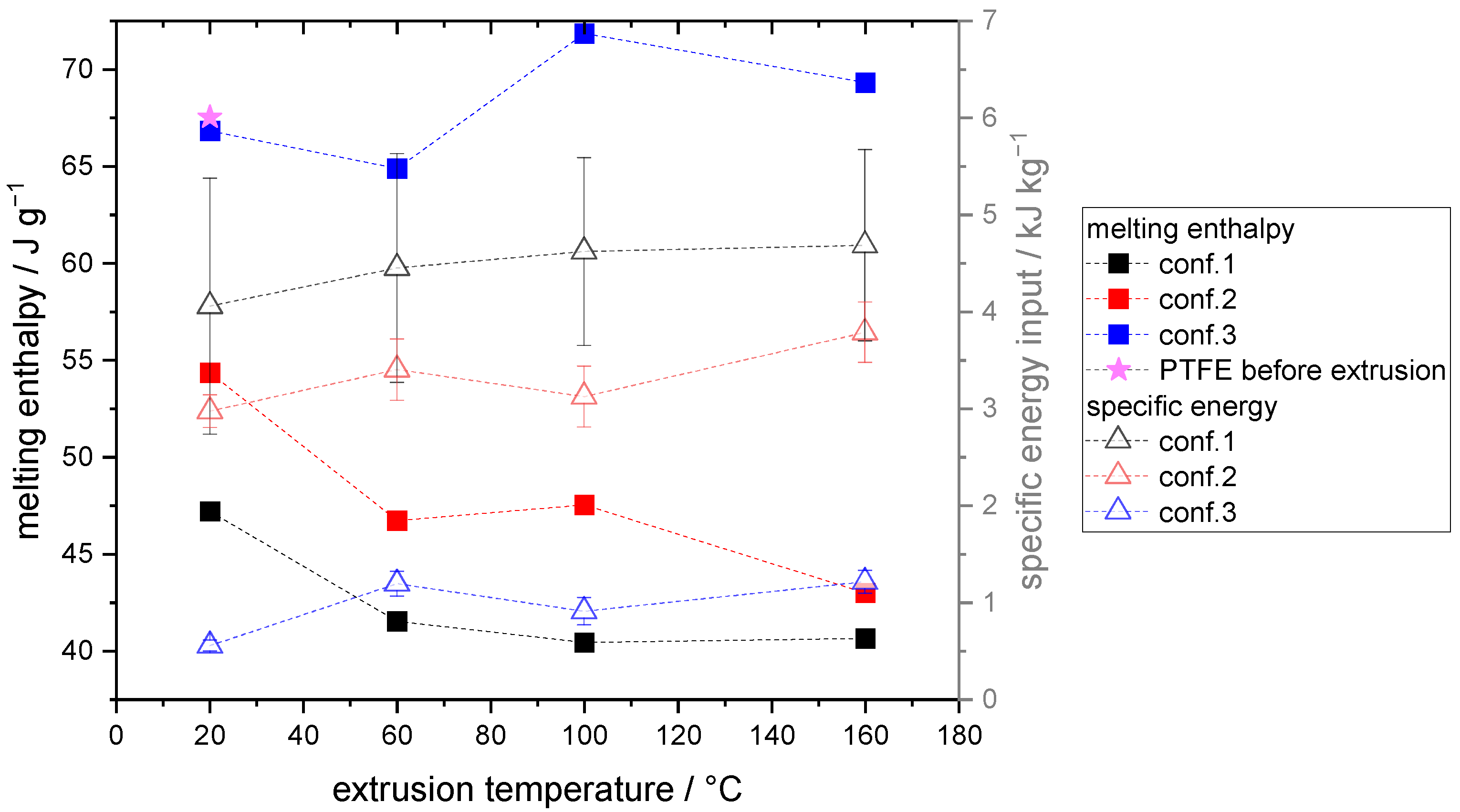
Figure 3 shows the specific energy input and melting enthalpy in dependency of the extruder configuration and temperature.
Figure 3 illustrates that the specific energy input increases with the use of screw configurations employing a higher number of kneading elements, which are primarily responsible for greater energy input. Conversely, a lower number of kneading elements, as seen in configuration 3, results in a shorter duration time of the PTFE within the extruder, leading to lower energy input. Configuration 1, characterized by the longest duration time and the highest number of kneading elements, results in the highest specific energy input during the dispersing process. Moreover, the extrusion temperature has a slight effect on the specific energy input. A small overall increase is observed with increasing extrusion temperature for the various screw configurations. Simultaneously, the melting enthalpy for configurations 1 and 2 decreases as the temperature increases between 20 and 60 °C. According to Tomkovic and Hatzikiriakos, above 30 °C, the disorder and thereby the degree of fibrillation increases, which correlates with the decreased melting enthalpy observed in configurations 1 and 2. In configuration 3, no trend in dependency on the extrusion temperature is evident, indicating that minimal fibrillation took place since the melting enthalpy of configuration 3 and the starting material of PTFE before extrusion are almost identical. For configurations 1 and 2, the degree of fibrillation, or the resulting melting enthalpy, correlates with the specific energy input. The higher the specific energy input, the lower the melting enthalpy observed, which could be attributed to a higher number of fibrils requiring greater torque from the extruder for processing.

3.3. Quantifying PTFE Fibrils in Semi-Dry Processed Cathodes

Based on preliminary studies that showed increased fibrillation behavior at 60 °C when exclusively using PTFE, an operating temperature of 60 °C was selected for the semi-dry processing of the cathode granules. Temperatures above 60 °C result in the evaporation of the solvent, leading to an inconsistent solids content of the extrudate. Moreover, a correlation between the degree of fibrillation and the specific energy input is anticipated according to the results of the preliminary study. Consequently, energy values were computed for the cathode extrudate using analogous methods of energy input analysis, which are illustrated in Figure 4a. The specific energy input decreases as the number of kneading elements is reduced. This finding is in line with the results of the initial studies that only employed PTFE. As a consequence, a higher degree of fibrillation is anticipated for conf. 1 in the cathode mixture, whereas conf. 3 is expected to have the lowest fibrillation degree. The melting enthalpy of the PTFE in the cathode mixture could not be quantified using DSC, likely due to the low amount of PTFE present in the mixture (1 wt.%), which leads to a non-quantifiable measurement signal. Consequently, further analysis is required to determine the electrode properties that are influenced by the binder structure of PTFE. Therefore, SEM images, also presented in Figure 4a, illustrate the differences in the microstructure of the binder within the cathode granules.
The figure shows noticeable structural differences in the extruded granules produced with different screw configurations. Specifically, the SEM images of the granules processed using conf. 3 exhibit fewer and larger (<600 nm) fibril bundles, while the granules processed with conf. 1 display a higher quantity of significantly smaller PTFE fibrils (<60 nm). The fibrils in the granules processed using conf. 2 are characterized by a medium size (<220 nm) and quantity. These differences in microstructure are correlated with the specific energy input during extrusion. Higher specific energy input results in a higher fibril quantity and a lower fibril size, which is also reflected in the melting enthalpy measurements conducted in the preliminary studies. However, conf. 3 showed almost no fibrillation according to the melting enthalpy measurements (see Figure 2). In the case of the cathode mixture, fibrils are visible within the cathode for conf. 3, which may be attributed to the slightly increased energy input for the extrusion of the cathode mixture against exclusively PTFE (1.5 to 1.3 Wh kg−1), or to the high specific surface area of carbon black and LFP, which can affect the extent of fibrillation. However, SEM images are inherently susceptible to stochastic variations, and further analyses are required to validate the observed results. Therefore, electric conductivity and mechanical adhesion testing of the processed cathodes were conducted to obtain more information about the structure-related electrode properties (see Figure 4b).
Based on Figure 4b, it is evident that the electric conductivity varies significantly among the different extrusion dispersion strategies. Specifically, conf. 1 exhibits a relatively low electric conductivity of 1.2 mS cm−1, while conf. 2 displays a slightly higher conductivity of 1.95 mS cm−1. The cathodes processed using conf. 3 exhibit the highest electric conductivity of 2.3 mS cm−1. These findings can be attributed to the structural differences illustrated in Figure 4a. Electrodes with fewer and larger fibril bundles (conf. 3) exhibit higher electric conductivities than those with more and smaller PTFE fibrils, due to the presence of non-conductive PTFE fibrils that isolate electric conductive pathways. These results are also consistent with the differences observed in standard deviation. A higher amount of fibrils (as seen in Figure 4b) corresponds to lower standard deviations in measured electric conductivity. This suggests that a more uniform distribution of smaller fibrils, as seen in cathodes processed by conf. 1, leads to lower measurement deviations than for cathodes with a smaller quantity of fibrils that are less uniformly distributed, as seen in the cathodes processed using conf. 3.
Similar to the electric conductivity, small differences in adhesion strength can be attributed to the dispersion strategies and resulting fibril structure. In this regard, a higher quantity of smaller fibrils, as observed in the cathodes processed using conf. 1, results in a slightly increased adhesion between substrate and electrode coating compared to cathodes with fewer fibrils, such as those processed using conf. 3. This is due to the increased number of fibrils forming more contacts towards the substrate and between LFP particles, resulting in higher adhesion forces.
Although the adhesion force of semi-dry manufactured LFP cathodes is relatively low, these electrodes exhibit favorable elastic behavior. This characteristic is beneficial for electrode processing, i.e., rolling up, confectioning, and cell assembly. Furthermore, the trend between adhesion force and the correlated fibril structure is not as evident as expected. Therefore, to further investigate the mechanical properties of the manufactured cathodes regarding elastic deformation behavior, nanoindentation is used, where 80 nanoindents are measured and their sum distribution is plotted in Figure 4c.
In line with the adhesion and conductivity results, Figure 4c reveals a clear trend in the elastic deformation of cathodes produced using different extrusion process strategies. Cathodes exhibiting a higher quantity of smaller fibrils, such as those manufactured with conf. 1, display a greater proportion of elastic deformation energy relative to total deformation energy. Conversely, the cathodes produced using conf. 3, which have fewer and larger fibrils (see Figure 4a), exhibit less elastic deformation and a wider sum distribution. This may be attributed to the formation of fewer connections between LFP particles, resulting in higher plastic deformation following mechanical stress. Furthermore, the strongly cross-linked particle structures found in the cathodes processed using conf. 1 absorb mechanical forces more effectively, and elastically compensate for them, than the cathodes processed using conf.3.
This section establishes a strong relationship between fibrillation extent, specific energy input during dispersion, electric conductivity, and mechanical properties. Based on the findings of the preliminary studies, the present study provides robust evidence for the correlation between these factors.
Furthermore, Figure 4b,c include data for a reference cathode, showing its electrical conductivity, adhesion strength, and elastic deformation behavior. This LFP reference is fabricated using conventional methods, employing a dissolver and a doctor blade coating technique, as outlined in the experimental section. PTFE fibrillation cannot be achieved with high solvent content and a dissolver for dispersion, as the pressure stress numbers and stress intensities are relatively low. Therefore, conventional processing was carried out using PVdF dissolved in NMP, to achieve the required mechanical properties for the further processing of the electrodes. Owing to the use of a different binder (PVdF) in a different quantity (4 wt.%) in the reference, a direct comparison of the binder structure is challenging. Nonetheless, the overall physical electrode properties can be compared. For instance, the conventionally processed reference exhibits significantly higher electrical conductivity and adhesion forces, while the relative elastic deformation is reduced and the sum distribution is considerably wider compared to the semi-dry processed cathodes. The impact of these observations on electrochemical properties and energy densities at the cell level will be demonstrated in the following section.

3.4. Electrochemical Performance of Semi-Dry Processed Cathodes Compared to Conventionally Manufactured Electrodes

To further assess the influence of the different process strategies and associated binder structures, an electrochemical analysis of the semi-dry processed cathodes was conducted in coin cells. The electrochemical properties and overall energy densities of the newly processed cathodes were compared to those of conventionally manufactured electrodes for a comprehensive evaluation and classification. The electrochemical analysis was carried out using half cells to measure cell performance independently of the anode side. The areal capacity of the cathodes was 2.5 mAh cm−2 while the electrode density was pre-investigated and set to 1.8 g cm−3 for further cell analysis, as shown in Supporting Information Figure S3. Given this electrode density, the specific discharge capacity is plotted as a function of different process strategies in Figure 5.
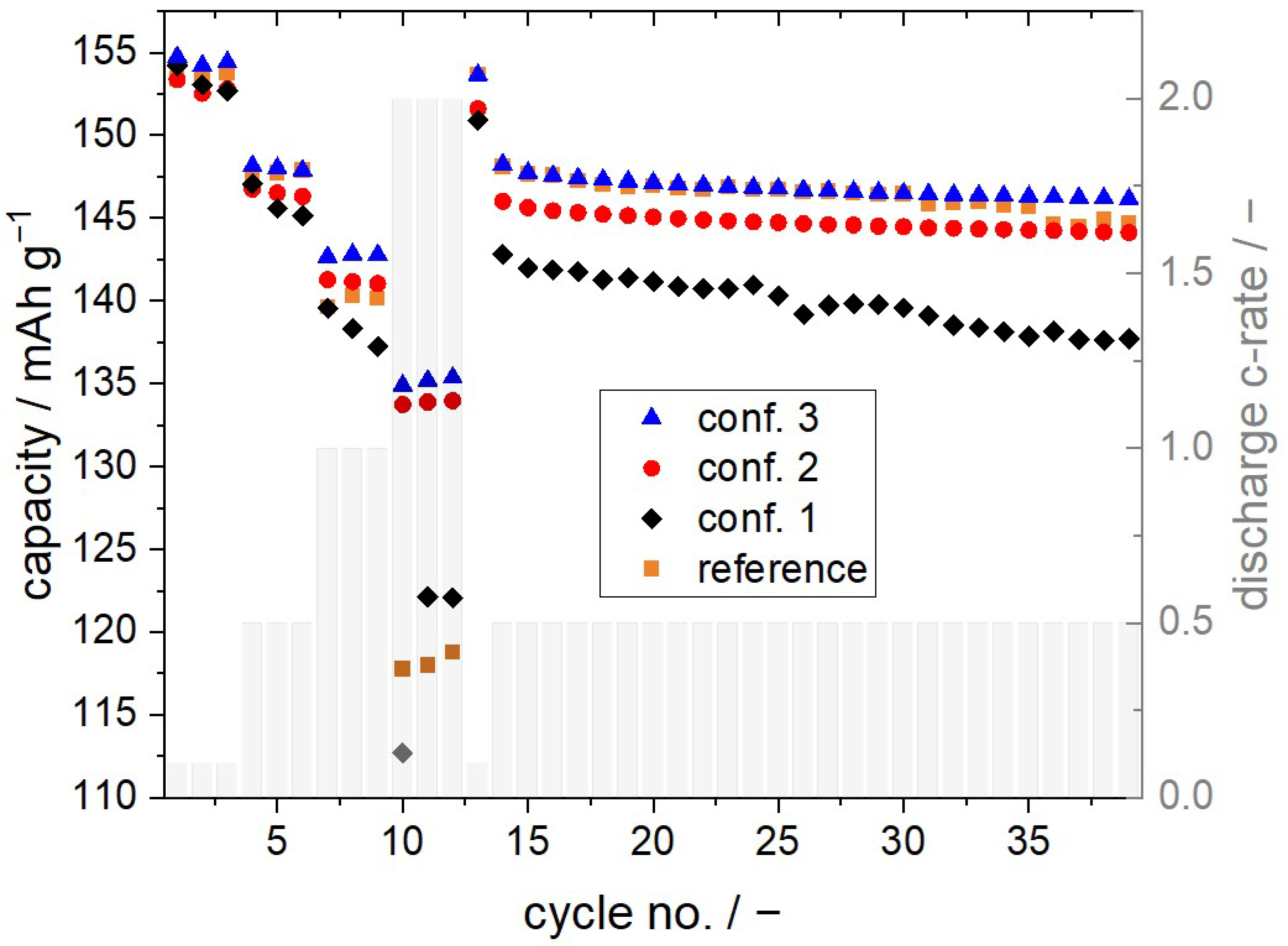
The discharge capacities of the cathodes were measured after formation (cycle 3) at a rate of 0.1 C, with conf. 3 and the reference having almost the theoretically calculated capacity value of LFP (155 mAh g−1), while conf. 2 had slightly lower discharge capacity and conf. 1 had the lowest. At a discharge rate of 0.5 C, a similar trend was observed, with conf. 3 and the reference having the highest capacities (of approximately 147 mAh g−1) and conf. 1 having the lowest. These results suggest that cathodes with a higher degree of fibrillation, such as conf. 1, have lower discharge capacities at a discharge rate equal to 0.5 C. This could be due to a limited capacity utilization of the active material, as a high number of fibrils may isolate conductive pathways connecting to the active material LFP. This is also supported by the electric conductivity measurements presented in Figure 4b, with conf. 1 having the lowest conductivity.
At the higher discharge rates of 1 and 2 C, the trend observed for the semi-dry processed electrodes is consistent, although the capacities of conf. 2 and conf. 3 seem to be nearly aligned. In contrast, the reference had relatively lower capacities at higher discharge rates compared to the semi-dry processed cathodes, with 138 mAh g−1 at 1 C and 122 mAh g−1 at 2 C, while conf. 3 reached 141 mAh g−1 at 1 C and 133 mAh g−1 at 2 C. Since the reference cathode is characterized by a higher electric conductivity, as shown in Figure 4b, electric limitations are an unlikely cause of this behavior. This is due to the observation that electrical conductivity is orders of magnitude higher than ionic conductivity. Given that even the ionic conductivity of the electrolyte is approximately 10−3 S cm−1 [28], and thus smaller than the electrical conductivity, it can be assumed that the conductivity within the electrodes is further reduced due to steric hindrance, making it still lower. Consequently, the rate performance is primarily limited by the relatively prolonged process of ionic conduction. This is consistent with previous findings reported by Gao et al. [7], where ionic limitations of LFP cathodes using PVdF as a binder were observed. To further analyze the electrochemical behavior, voltage over capacity plots were investigated, as shown in Figure 6. Additionally, the voltage over capacity plot for the charging process is visualized in Figure S4 (Supplementary Materials).
Based on the voltage over capacity plot obtained at a discharge rate of 0.1 C, it was observed that the nominal voltage remained relatively constant at 3.4 V for all investigated cathodes, regardless of the manufacturing approach employed. However, reduced capacity utilization was noted for conf. 1 and 2. At the higher discharge rate of 0.5 C, an increased overpotential was observed for the reference. Overpotentials indicate the difference between the theoretical redox potential and the actually measured redox potential. In the case of cell discharge, a high overpotential implies that the lower cut-off voltage is reached prematurely. When the discharge rates were further increased to 1 C and 2 C, even higher overpotentials were recorded for the reference, leading to a premature end of discharge voltage and, consequently, a reduced specific discharge capacity. These high overpotentials are attributed to the ionic transport limitations resulting from the binder structure of PVdF, which forms isolating layers that block the Li+-ion pathways. Impedance measurements, using a blocking electrode configuration set-up according to Landesfeind et al. [26], were conducted to validate these results. Regarding these measurements, it is shown that the reference is characterized by a significantly higher ionic diffusion resistance (391.34 Ω) compared to the semi-dry processed cathodes (e.g., conf. 3: 215.12 Ω). More detailed results regarding the measurement of the diffusion resistance can be found in Supporting Information Figure S5.
Overall, a negligible difference in overpotentials was observed for the semi-dry processed cathodes, independent of the discharge rate. However, the utilization of the active material varied depending on the screw configuration used. Therefore, in addition to the capacity results presented in Figure 5 and Figure 6, the overall specific energy output of the LFP-cathodes, characterized in half cells, is plotted in
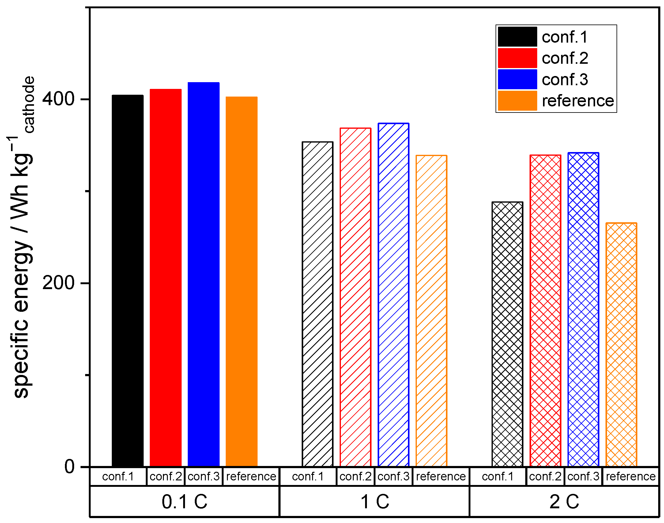
 Figure 7.
Figure 7 presents the specific energy results, where the total mass of the cathode, including the aluminum substrate, is considered. The specific energy of the cathodes processed using semi-dry techniques, such as conf. 2 and conf. 3, is higher than that of the reference cathode. This can be attributed to the lower content of binder (1 wt.% PTFE), resulting in a higher content of active material, which in turn leads to increased specific energy. Furthermore, at higher current rates (1 and 2 C), the semi-dry processed electrodes show even higher specific energies compared to the reference electrode due to the aforementioned overpotential reduction. Since the active material content and overpotentials are almost similar for all semi-dry processed electrodes, the resulting relatively small differences are only affected by the extent of fibrillation, which correlates with the amount of accessible active material.
Overall, it has been demonstrated that semi-dry processed cathodes can be at least as electrochemically efficient as conventionally manufactured cathodes, approaching the overall theoretical capacity of 155 mAh g−1 at a C-rate of 0.1 C according to the active material supplier. Indeed, by establishing a specific degree of binder, fibrillation according to conf. 3 capacities at higher C-rates of 2 C can be up to 10 % higher compared to the conventionally manufactured reference. Additionally, the semi-dry processed electrodes are capable of achieving even higher energy densities per unit mass of the cathode due to the increased content of active material and relatively lower overpotentials.

3.5. Energy Required for Electrode Production

Another criterion for classifying the process in comparison to the reference is the amount of energy required for electrode production per generated Wh of the fabricated cells. In this regard, data on the energy consumption of the process steps dispersion, coating, drying, and calendering, were recorded and are illustrated in Figure 8.
It is evident that the energy consumption of the semi-dry process is significantly reduced, particularly in the subprocesses of coating and drying. This high energy consumption for the conventional reference is largely attributable to the heating of convective dryers and the subsequent treatment of the evaporated solvent NMP. This consumption is substantially lower for the semi-dry process route due to the reduced solvent content, consisting mainly of water, as well using the more energy efficient conductive instead of convective heating. Conductive drying allows for the transfer of larger amounts of energy to the wet electrode within a shorter time frame compared to convective methods. This results in increased drying rates (by approximately a factor of 2) and reduced drying times. In the case of the low-viscosity reference suspension, there can be sedimentation phenomena, leading to a distribution gradient of inactive and active materials [29]. The initial form of the granules in the semi-dry process is already consolidated, which prevents any demixing, even at high drying rates. Additionally, there is an elimination of additional energy, investment, and space requirements for calendering, as a result of the aforementioned process integration.
Nevertheless, it should be noted that these energy measurements were obtained using equipment corresponding to a maximum TRL level of 4 to 5. Therefore, the data may not be directly transferable to an industrial scale. In addition, water-based alternatives to conventional LFP processing are state-of-the-art, eliminating the need for NMP processing and the associated energy costs. Nonetheless, the significance and clarity of the results indicate a substantial energy saving in the semi-dry process (a relative reduction of approximately 80%), which, in conjunction with reduced investment and space requirements, is clearly relevant on an industrial scale.

4. Conclusions

In this study, the authors have developed an innovative water-based process for manufacturing LFP cathodes, characterized by comprehensive process integration and reduced energy consumption. This novel approach utilizes extrusion and calendering techniques to process slurries with a 55% higher solids content compared to conventional methods, effectively integrating the individual steps of coating, drying, and calendering into a single machine. For this, the selection of a suitable binder becomes a critical aspect of implementing this process. Consequently, we chose PTFE as the binder additive. The structure of PTFE was observed to be significantly influenced by the employed process parameters.
The findings indicate that a higher specific energy input leads to reduced melting enthalpy, signifying more pronounced fibrillation. Subsequently, we conducted further analyses to investigate structure-related properties within the PTFE cathode composite. To accomplish this, we examined structural variances using SEM images, revealing that a higher specific energy input results in a greater number of smaller fibrils. Interestingly, electrodes with fewer and larger fibril bundles exhibit superior electrical conductivities compared to those with numerous and thinner PTFE fibrils. Additionally, LFP cathodes with a greater degree of fibrillation exhibit favorable elastic behavior, which facilitates electrode processing for rolling, assembly, and confectioning. Regarding electrochemical data, the specific discharge capacity demonstrated that cathodes with a higher degree of fibrillation exhibit lower discharge capacities.
In comparison to conventionally processed PVdF-containing reference cathodes, we achieved up to a 10% increase in discharge capacity at high C-rates (2 C). The analysis of the voltage–capacity relationship revealed that the overpotentials in the conventional reference, especially at high C-rates, can be attributed to ionic transport limitations caused by the binder structure of PVdF. This structure forms isolating layers that obstruct the pathways for Li+ ions. Impedance measurements were conducted to validate these findings.
Finally, we calculated the overall specific energy output at the electrode level, revealing that the specific energy of cathodes processed using semi-dry techniques exceeded that of the reference cathode. This was attributed to the aforementioned improvements in electrochemical properties and the lower binder content (1 wt.% PTFE instead of 4 wt.% PVdF), resulting in a higher content of active material. In addition to energy output, we tracked energy consumption, noting a substantial reduction of approximately 80%. This finding highlights the increased relevance of the novel semi-dry process for industrial applications, also considering space and machinery investment reductions.

Supplementary Materials

The following supporting information can be downloaded at: https://www.mdpi.com/article/10.3390/batteries9120567/s1, Figure S1: Surface tension of solvent and contact angle towards LFP of solvent in dependency of the mass percentage of IPA within the solvent; Figure S2: Cathode surface in dependence of the coating application temperature; Figure S3: Discharge capacity of conf.1 in dependency of the electrode density; Figure S4: Voltage over capacity plots for the different cycle no. at a constant charge rate of 0.1 C in dependency of processing strategies; Figure S5: Equivalent circuit model used for EIS measurement fitting (a); impedance spectrum and fit for reference (b) and conf. 3 cell (c); and BET surface area (d).

Author Contributions

The individual author contributions are as follows. Conceptualization, E.W.; methodology, E.W., S.F. and M.L.; validation, E.W., S.F. and M.L.; formal analysis, E.W.; investigation, E.W. and S.F.; data curation, E.W., S.F. and M.L.; writing—original draft preparation, E.W.; writing—review and editing, S.F., M.L. and A.K.; visualization, E.W.; supervision, A.K.; project administration, E.W.; funding acquisition, E.W. and A.K. All authors have read and agreed to the published version of the manuscript.

Funding

This research was funded by Bundesministerium für Bildung und Forschung (BMBF), grant number 03XP0344A (acronym: GranuProd). The publication fee was financially supported by the TU Braunschweig Publication Fund.

Data Availability Statement

The data presented in this study are available in this article and the supporting information.

Acknowledgments

The authors would like to thank the Projektträger Jülich (PTJ) for the coordination of the project GranuProd.

Conflicts of Interest

The authors declare no conflict of interest.

References

  1. Wood, D.L.; Quass, J.D.; Li, J.; Ahmed, S.; Ventola, D.; Daniel, C. Technical and economic analysis of solvent-based lithium-ion electrode drying with water and NMP. Dry. Technol. 2018, 36, 234–244. [Google Scholar] [CrossRef]
  2. Bresser, D.; Buchholz, D.; Moretti, A.; Varzi, A.; Passerini, S. Alternative binders for sustainable electrochemical energy storage—The transition to aqueous electrode processing and bio-derived polymers. Energy Environ. Sci. 2018, 11, 3096–3127. [Google Scholar] [CrossRef]
  3. von Drachenfels, N.; Husmann, J.; Khalid, U.; Cerdas, F.; Herrmann, C. Life Cycle Assessment of the Battery Cell Production: Using a Modular Material and Energy Flow Model to Assess Product and Process Innovations. Energy Technol. 2023, 11, 2200673. [Google Scholar] [CrossRef]
  4. Wiegmann, E.; Kwade, A.; Haselrieder, W. Solvent Reduced Extrusion-Based Anode Production Process Integrating Granulate Coating, Drying, and Calendering. Energy Technol. 2022, 10, 2200020. [Google Scholar] [CrossRef]
  5. Zubi, G.; Dufo-López, R.; Carvalho, M.; Pasaoglu, G. The lithium-ion battery: State of the art and future perspectives. Renew. Sustain. Energy Rev. 2018, 89, 292–308. [Google Scholar] [CrossRef]
  6. Park, O.K.; Cho, Y.; Lee, S.; Yoo, H.-C.; Song, H.-K.; Cho, J. Who will drive electric vehicles, olivine or spinel? Energy Environ. Sci. 2011, 4, 1621. [Google Scholar] [CrossRef]
  7. Gao, S.; Su, Y.; Bao, L.; Li, N.; Chen, L.; Zheng, Y.; Tian, J.; Li, J.; Chen, S.; Wu, F. High-performance LiFePO4/C electrode with polytetrafluoroethylene as an aqueous-based binder. J. Power Sources 2015, 298, 292–298. [Google Scholar] [CrossRef]
  8. MacNeil, D.D.; Lu, Z.; Chen, Z.; Dahn, J.R. A comparison of the electrode/electrolyte reaction at elevated temperatures for various Li-ion battery cathodes. J. Power Sources 2002, 108, 8–14. [Google Scholar] [CrossRef]
  9. Porcher, W.; Moreau, P.; Lestriez, B.; Jouanneau, S.; Le Cras, F.; Guyomard, D. Stability of LiFePO4 in water and consequence on the Li battery behaviour. Ionics 2008, 14, 583–587. [Google Scholar] [CrossRef]
  10. Porcher, W.; Moreau, P.; Lestriez, B.; Jouanneau, S.; Guyomard, D. Is LiFePO4 Stable in Water? Electrochem. Solid-State Lett. 2008, 11, A4. [Google Scholar] [CrossRef]
  11. Zhang, X.; Ge, X.; Shen, Z.; Ma, H.; Wang, J.; Wang, S.; Liu, L.; Liu, B.; Liu, L.; Zhao, Y. Green water-based binders for LiFePO4/C cathodes in Li-ion batteries: A comparative study. New J. Chem. 2021, 45, 9846–9855. [Google Scholar] [CrossRef]
  12. Priyono, S.; Lubis, B.M.; Humaidi, S.; Prihandoko, B. Heating Effect on Manufacturing Li4Ti5O12 Electrode Sheet with PTFE Binder on Battery Cell Performance. IOP Conf. Ser. Mater. Sci. Eng. 2018, 367, 12007. [Google Scholar] [CrossRef]
  13. Dhanumalayan, E.; Joshi, G.M. Performance properties and applications of polytetrafluoroethylene (PTFE)—A review. Adv. Compos. Hybrid Mater. 2018, 1, 247–268. [Google Scholar] [CrossRef]
  14. Feng, S.; Zhong, Z.; Wang, Y.; Xing, W.; Drioli, E. Progress and perspectives in PTFE membrane: Preparation, modification, and applications. J. Membr. Sci. 2018, 549, 332–349. [Google Scholar] [CrossRef]
  15. Arajelian, V.G.; Boggs, S.; Borsi, H.; Boulter, E.A.; Buchholz, V.; Cherney, E.A.; Cherukupalli, S.; Colwell, M.; Cooper, J.; Cotton, I.; et al. 2004 Index IEEE Electrical Insulation Magazine Vol. 20. IEEE Electr. Insul. Mag. 2004, 20, 69–76. [Google Scholar] [CrossRef]
  16. Tomkovic, T.; Hatzikiriakos, S.G. Rheology and processing of polytetrafluoroethylene (PTFE) paste. Can. J. Chem. Eng. 2020, 98, 1852–1865. [Google Scholar] [CrossRef]
  17. Zhang, Y.; Huld, F.; Lu, S.; Jektvik, C.; Lou, F.; Yu, Z. Revisiting Polytetrafluorethylene Binder for Solvent-Free Lithium-Ion Battery Anode Fabrication. Batteries 2022, 8, 57. [Google Scholar] [CrossRef]
  18. Kang, J.M.; Kim, H.W.; Jang, Y.S.; Kim, H.; Ryu, J.H. Thick Positive Electrode using Polytetrafluorethylene (PTFE) Binder for High-Energy-Density Lithium-ion Batteries. Korean Electrochem. Soc. 2021, 24, 28–33. [Google Scholar] [CrossRef]
  19. Kim, N.-I.; Lee, C.-B.; Seo, J.-M.; Lee, W.-J.; Roh, Y.-B. Correlation between positive-electrode morphology and sulfur utilization in lithium–sulfur battery. J. Power Sources 2004, 132, 209–212. [Google Scholar] [CrossRef]
  20. Li, G. The influence of polytetrafluorethylene reduction on the capacity loss of the carbon anode for lithium ion batteries. Solid State Ion. 1996, 90, 221–225. [Google Scholar] [CrossRef]
  21. Liu, W.; Huang, X.; Guobao, L.; Wang, Z.; Huang, H.; Zhonghua, L.; Xue, R.; Chen, L. Electrochemical and X-ray photospectroscopy studies of polytetrafluoroethylene and polyvinylidene fluoride in Li/C batteries. J. Power Sources 1997, 68, 344–347. [Google Scholar] [CrossRef]
  22. Pace, G.T.; Wang, H.; Whitacre, J.F.; Wu, W. Comparative study of water-processable polymeric binders in LiMn2O4 cathode for aqueous electrolyte batteries. Nano Sel. 2021, 2, 939–947. [Google Scholar] [CrossRef]
  23. Suh, Y.; Koo, J.K.; Im, H.; Kim, Y.-J. Astonishing performance improvements of dry-film graphite anode for reliable lithium-ion batteries. Chem. Eng. J. 2023, 476, 146299. [Google Scholar] [CrossRef]
  24. Haselrieder, W.; Westphal, B.; Bockholt, H.; Diener, A.; Höft, S.; Kwade, A. Measuring the coating adhesion strength of electrodes for lithium-ion batteries. Int. J. Adhes. Adhes. 2015, 60, 1–8. [Google Scholar] [CrossRef]
  25. Westphal, B.G.; Mainusch, N.; Meyer, C.; Haselrieder, W.; Indrikova, M.; Titscher, P.; Bockholt, H.; Viöl, W.; Kwade, A. Influence of high intensive dry mixing and calendering on relative electrode resistivity determined via an advanced two point approach. J. Energy Storage 2017, 11, 76–85. [Google Scholar] [CrossRef]
  26. Landesfeind, J.; Hattendorff, J.; Ehrl, A.; Wall, W.A.; Gasteiger, H.A. Tortuosity Determination of Battery Electrodes and Separators by Impedance Spectroscopy. J. Electrochem. Soc. 2016, 163, A1373–A1387. [Google Scholar] [CrossRef]
  27. Ariawan, A.B.; Ebnesajjad, S.; Hatzikiriakos, S.G. Properties of polytetrafluoroethylene (PTFE) paste extrudates. Polym. Eng. Sci. 2002, 42, 1247–1259. [Google Scholar] [CrossRef]
  28. Wu, Y. Lithium-Ion Batteries: Fundamentals and Applications; CRC Press: Boca Raton, FL, USA, 2015; ISBN 9781466557345. [Google Scholar]
  29. Westphal, B.; Bockholt, H.; Günther, T.; Haselrieder, W.; Kwade, A. Influence of Convective Drying Parameters on Electrode Performance and Physical Electrode Properties. ECS Trans. 2015, 64, 57–68. [Google Scholar] [CrossRef]
Figure 1. Schematic drawing of LFP cathode production using twin-screw extrusion for dispersing and a calender for coating.
Batteries 09 00567 g001
Figure 2. Types of screw configurations used with varying kneading and conveying elements.
Batteries 09 00567 g002
Figure 3. Melting enthalpy and specific energy input in dependency of extrusion screw configuration and temperature.
Batteries 09 00567 g003
Figure 4. (a) SEM pictures of cathode granules in dependency of different screw configurations; (b) adhesion strength and electric conductivity in dependency of different dispersion strategies; (c) sum distribution of relative elastic work in dependency of different manufacturing strategies measured by nanoindentation.
Batteries 09 00567 g004
Figure 5. Specific discharge capacities for half cells in dependency of different manufacturing strategies.
Batteries 09 00567 g005
Figure 6. Voltage over capacity plots for the discharge rate of 0.1 (cycle 13), 0.5 (cycle 6), 1 (cycle 9), and 2 C (cycle 12) in dependency of different processing strategies.
Batteries 09 00567 g006
Figure 7. Specific energy at the cathode level at 0.1 (cycle 13), 1 (cycle 9), and 2 C (cycle 12) in dependency of different processing strategies.
Batteries 09 00567 g007
Figure 8. Specific energy consumption of electrode manufacturing steps dispersing, coating, drying, and calendering for the conventional and semi-dry process route at the same throughput.
Batteries 09 00567 g008
Table 1. Recipes of raw materials for processed cathodes.
TypeSemi-Dry Cathode [wt.%]Reference [wt.%]
LFP9491
carbon black55
PTFE1-
PVdF-4
Table 2. Cycling procedure of half cells.
PurposeCharge ParameterDischarge ParameterNo. of Cycles
FormationCC (0.1 C; 4.2 V)CC (0.1 C; 2.5 V)2
Capacity checkCCCV (0.1 C; 4.2 V)CC (0.1 C; 2.5 V)1
Discharge rate testCCCV (0.2 C; 4.2 V)CC ([0.5; 1; 2] C; 2.5 V)9
Capacity checkCCCV (0.1 C; 4.2 V)CC (0.1 C; 2.5 V)1
Cycling testCCCV (0.2 C; 4.2 VCC (0.5 C; 2.5 V)50
Disclaimer/Publisher’s Note: The statements, opinions and data contained in all publications are solely those of the individual author(s) and contributor(s) and not of MDPI and/or the editor(s). MDPI and/or the editor(s) disclaim responsibility for any injury to people or property resulting from any ideas, methods, instructions or products referred to in the content.

