1. Introduction
Lithium metal batteries (LMBs) are expected to play an increasingly important role in the automotive sector during the coming decades [
1]. However, the industrial development of LMBs needs to overcome a series of issues regarding materials and interfaces [
2]. Indeed, more rigid constraints are required on the electrolyte design with respect to lithium-ion batteries (LIBs): in addition to high conductivity, chemical and electrochemical stability against the electrodes, low flammability, and environmental sustainability [
3], the electrolytes for LMBs must be able to block the formation of lithium dendrites, e.g., by forming a stable solid electrolyte interface (SEI) towards the metal anode and/or by constituting a rigid barrier by themselves [
4,
5]. Among the solutions proposed in the literature, Janus membranes (JMs) could play a major role [
6]. These membranes take their name from the ancient Roman god Janus, “two-faced”, and are characterized by having two faces with different chemicophysical and functional properties.
The Janus concept was recently applied to both LIBs and beyond-lithium batteries. On the LIB side, Oh et al. demonstrated dual (ion/electron)-conductive/chemically active (i.e., able to chelate heavy metal ions) JMs based on a heterolayered nanofiber mat architecture [
7]. Later, Zhang et al. reported on all-nanomaterial JMs for acid scavenging and manganese ions trapping in LiMn
2O
4 LIBs. These separators were produced with interpenetrating hydroxyapatite/bacterial cellulose fibers integrated with a nanofibrous poly(mphenylene isophthalamide) (PMIA) support membrane by electrospinning [
8].
On the beyond-lithium batteries side, a great deal of work was devoted to the improvement of lithium–sulfur cells by developing JMs with the double aim to stabilize the lithium metal interface and (most importantly) to block/reduce the polysulfide shuttle [
9,
10,
11,
12,
13,
14,
15,
16,
17,
18,
19]. Zhou et al. developed JMs containing a single sodium ion-conducting side and a functional low-dimensional material (MXene)-coated side. When employed in room-temperature sodium–sulfur batteries, these JMs showed improved performance in enhancing electrolyte wettability, and inhibiting polysulfide diffusion and sodium dendrite growth [
20].
On the side of LMBs, Xu et al. reported a polymeric one-sided conductive JM with quasi-oriented pores prepared via directional ice templating and phase inversion from electrically conducting polyaniline (PANI) and insulating polyvinyl alcohol (PVA). The basic idea was that PANI surface could reduce locally concentrated currents promoting the formation of an even and stable solid electrolyte interface (SEI) layer, thereby solving the uneven germination of lithium dendrites and low Coulombic efficiency. At the same time, the pores that are oriented nearly perpendicular to the separator surface would improve affinity to the electrolyte and shorten ion diffusion pathways [
21]. Xie et al. used two molecular sieves, MCM-41 and SAPO-34, as functional modification layers to design JMs for LMBs [
22]. Due to the presence of Li-philic groups and the confinement effect of its pores, MCM-41 could provide fast transportation channels for Li
+ ions and ensure their uniform distribution. The SAPO-34 is highly selective for Li
+ ions and could work as an “ion rectifier” to redistribute Li ions.
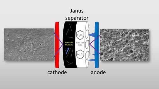
Lastly, Gonzales et al. [
23] discussed an interesting “fail safe” mechanism for internal short circuits to mitigate thermal runaway and catastrophic battery failure. To this aim, they fabricated a nanocomposite JM encompassing a PVDF-HFP gel polymer electrolyte (GPE), SiO
2, and carbon nanotubes (CNTs) as fillers, with a fully electronically insulating layer towards the anode and a partially electronically conductive (PEC) layer with adjustable conductivity, coming into contact with the cathode to intercept dendrites and control internal short-circuit resistance. They demonstrated that LMBs performed normally before shorting and then showed a gradual increase in internal self-discharge due to PEC-mitigated shorting.
Post-mortem analysis showed that the PEC layer did not block dendrite growth but intercepted them, allowing for a short circuit to occur in a gradual and safer fashion, which led to more manageable current and temperature increases.
In this paper, we moved from the results of Gonzales et al. to prepare JMs by means of a simpler recipe. In fact, we did not exploit a phase inversion method to prepare the polymer matrix in order to avoid dibutyl phthalate as a plasticizer, but employed a standard solvent-casting procedure with acetone and propylene carbonate, which are greener and more sustainable than dibutyl phthalate is. In addition, we substituted SiO
2 with Al
2O
3, which is expected to be less reactive in battery environment. We explored two configurations: Al
2O
3 added only in the insulating layer (JM “HALF”) or in both layers (JM “FULL”). The membranes were then activated with a standard electrolyte solution to obtain a gel polymer electrolyte (GPE) [
23]. Lastly, we evaluated the effect of JM thickness on the functional properties compared with that of a standard Celgard
TM (Celgard LCC, Charlotte, NC, USA) separator. As stated, the main advantage of JMs is the possibility of implementing different functional properties on the two sides of a separator. Here, the layer on the anode side offers greater resistance towards the formation of lithium dendrites. The layer on the cathode side provides better interface properties (less ohmic resistance) towards the electrode thanks to the presence of an electron-conducting phase.
2. Results
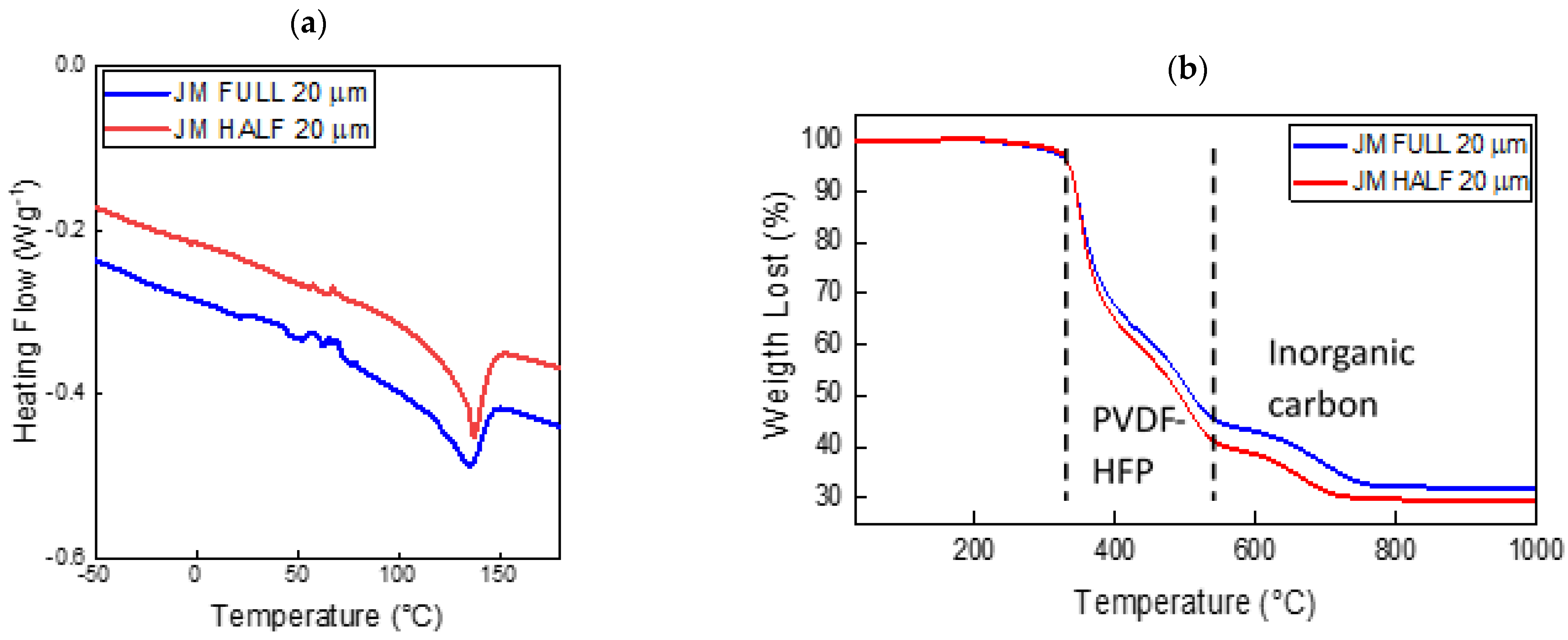
Figure 1 reports the thermal properties of the 20 μm HALF and FULL JMs as prepared, i.e., before the activation with the electrolyte solution (see
Section 3). The DSC thermogram (
Figure 1a) shows some exothermic features from room temperature to about 80 °C that were due to residual solvent evaporation. The amount of residual solvent was less than 2 wt %, as revealed by the TGA curve reported in
Figure 1b. The large endotherm observed for both samples in the range of 100–150 °C was due to the melting of the crystalline polymer fraction of the P(VDF-HFP) copolymer [
24]. The glass transition of PVDF-based matrices around −30 °C is hardly observed in these electrolytes [
3]. Interestingly, the DSC curves of the HALF and FULL JMs showed a nearly constant difference in the order of 0.7 W g
−1 in the heating flow. The observed difference was attributed to the different compositions of the conducting layers, as Al
2O
3 was present in the FULL JM but not in the HALF one. This caused a variation in the overall heat capacity and consequently the specific heat.
Figure 1b shows the TGA curves of the same samples. Both Janus membranes were stable up to ~330 °C. The losses in the temperature range of 330–540 °C were due to the decomposition of the polymer matrix [
24]. As a matter of fact, the nominal polymer weight fraction was 51.5 and 60 wt % in the FULL and HALF JMs, respectively, in good agreement with the losses observed in the TGA curves. The weight loss in the temperature region of 600–800 °C was due to the partial oxidation of the inorganic carbon fraction (Super P and MWCNTs), which generates gaseous CO
x byproducts. In fact, the TGA experiments were performed in an air atmosphere. The residual solid fraction above 800 °C was due to Al
2O
3 and partially unreacted MWCNTs.
Figure 2 shows the SEM images of the 20 μm HALF and FULL JMs before and after activation with the electrolyte solution, which produced a gel polymer electrolyte. The conducting layers of the as-prepared samples were flatter and more homogeneous than the insulating ones. In particular, the conductive layer was more homogeneous because it was deposited in contact with the base surface (glass). Its roughness was of the order of 100 nm. The insulating layer was left free to evolve following the evaporation of the solvent and had a roughness of the order of microns, as estimated from the SEM images. The activation process did not determine strong variations in the morphologies, but for the conducting side of the FULL JMs. Here, a significant increase in the porosity, always in the micrometer range, could be observed. The swelling effect due to liquid absorption was not evident, likely because of the high crystallinity (~70%) of the P(VDF-HFP) that we employed [
25]. The SEM pictures illustrating the elemental distribution and the EDX spectra for a FULL membrane both before and after cycling are reported in
Supplementary Materials (Figures S1–S4). The analysis shows a uniform distribution of Al
20
3 before cycling, which was not modified by the charge–discharge experiments (see below).
Figure 3a,b report the Nyquist plots of the electrochemical impedance spectroscopy measurements performed on the 20 μm HALF and FULL JMs. Ionic bulk conductivity, σ,was simply obtained from the resistance measured by considering the high-frequency intercepts with the
x axis.
Figure 3c reports the Arrhenius plots of the ionic conductivity for the 20 μm HALF and FULL JMs. In both cases, the behavior of the ionic conductivity is well-described by the semiempirical Vogel–Tammann–Fulcher (VTF) equation (see, for example, [
3]):
where
is an exponential prefactor that can be related to the number of charge carriers,
is pseudo-activation energy for the ionic transport expressed in Kelvin, and
is an adjustable parameter that may be related to the ideal glass transition temperature, i.e., the value that could be ideally obtained with a DSC experiment performed under adiabatic conditions (heating rate tending to zero). The VTF behavior is typical in those systems characterized by large free volume, e.g., glasses and polymers above the glass transition or GPEs, as in the present case [
3]. The best-fit parameters of Equation (1) are reported in
Table 1. The activation energies expressed in electronvolt are typical of electrolytes following VTF behavior. As a matter of fact, the activation energy of the FULL JMs was lower than that of the HALF ones, which explains the higher conductivity at low temperature.
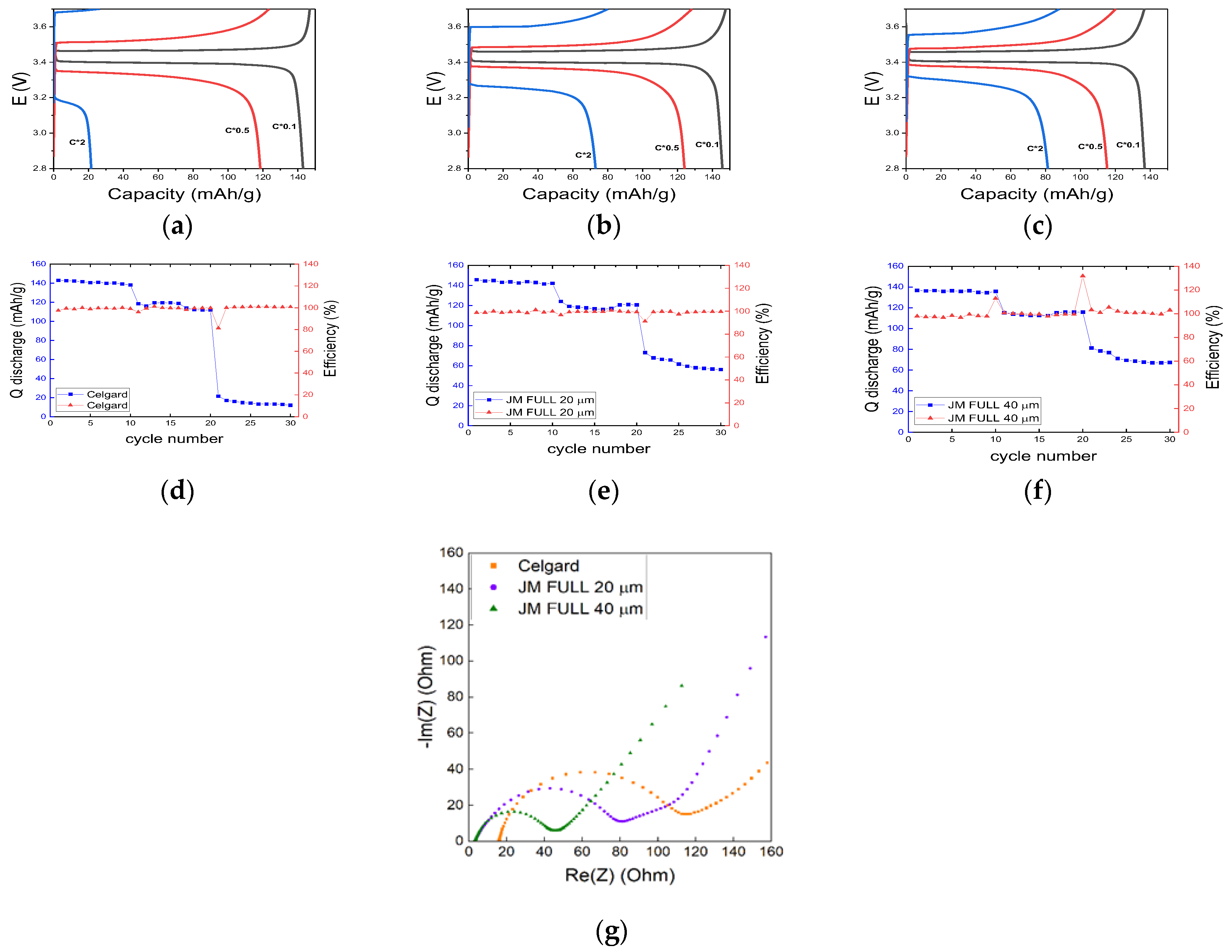
Figure 4 shows the charge/discharge GCPL experiments performed at C/10, C/2, and 2C on the Li/separator/LFP full cell, respectively. As the separator, we compared Celgard
TM and two FULL Janus membranes with different thickness levels: 20 μm (FULL 20) and 40 μm (FULL 40) (
Figure 4a–c). Ten cycles were performed for each C-rate, whose resulting specific capacity and Coulombic efficiency are shown in
Figure 4d–f. The three separators behaved nearly the same at low C-rates. In fact, specific capacities of ~140 and ~120 mAhg
−1 were obtained at C/10 and C/2, respectively, for the Celgard
TM separator and the two JMs. In contrast, the JMs behaved better than the Celgard
TM at 2C. In fact, the cell encompassing FULL 40 and FULL 20 reached ~60 and ~50 mAhg
−1, respectively, whereas the cell using Celgard
TM had a specific capacity limited to ~10 mAhg
−1. For all the investigated cells, the Coulombic efficiency was always very near to 100%, independently from the C-rate. GCPL experiments performed on the HALF JMs achieved much worse performance than that on the FULL ones (results not shown).
Indeed, LFP is well-established as a cathode active material, and high-rate performance was reported in the literature with Celgard
TM separators and standard electrolytes [
26]. We do not have a clear-cut explanation for the slump in performance that we obtained at 2C for the Celgard
TM-based cell. However, we performed comparative analysis under the same conditions of preparation as that for the coin cells, so we are confident that our relative results are acceptable.
The FULL 40 JM was characterized by lower (less than 0.1 V) overpotential than that of FULL 20. This is likely attributed to better interfacial properties, which translate into the lower charge transfer resistance, R
ct, as shown by the EIS results reported in
Figure 4g. Here, the Nyquist plot showed R
ct ≅ 40 ohm for FULL 40, vs. R
ct ≅ 80 ohm for FULL 20. The charge transfer resistance of the Celgard
TM-based cell was about 100 ohm. Pan et al. reported a value of 550 ohm for their pouch cell employing LP40 (i.e., 1.0 M lithium hexafluorophosphate in ethylene carbonate (EC)/diethyl carbonate (DEC) (1/1
v/
v, BASF) electrolyte solution [
26].
The overall morphology and microstructure of the JM is well-maintained upon cycling, as shown by the SEM-EDX maps and by the backscattered electron images reported in
Figures S1–S4 for both the isolating and the conducting layers of the FULL 40 membrane. The overall mechanism of action carried out by the JMs is shown in
Figure 5. As expected, the insulating layer helped in increasing the resistance of the separator against the formation of lithium dendrites, while the conductive layer positioned in contact with the cathode improved the electrical properties of the interface, allowing for a more effective charge transfer [
23,
26].
3. Materials and Methods
3.1. CNTs Purification
Multiwalled carbon nanotubes (MWCNTs, Sigma-Aldrich, Milano, Italy; 95% purity; outer diameter × wall thickness × length: 20–30 nm × 1–2 nm × 0.5–2 μm) were purified in an acid solution to eliminate the metal catalysts and impurities from their synthesis. We prepared a 12% HCl suspension in a volumetric ratio of 1:1 with the nanotubes, which was sonicated for 10 min and then heated in an oil bath at 80 °C for 3 h under continuous stirring. MWCNTs were filtered under vacuum, rinsed to neutrality, and dried at 80 °C under vacuum overnight.
3.2. Preparation of the Insulating Slurry
Poly(vinylidene fluoride hexafluoro propylene) (P(VDF-HFP), Kynar Flex 2801, Arkema S.r.l., Spinetta Marengo, Italy) and Al2O3 (Sigma-Aldrich, d < 50 nm), in a ratio of 3:2 w/w, were dissolved in acetone (Alfa Aesar, Haverhill, MA, USA, 98%). A total of 10 ml of acetone was used for 1 g of solid mass. Then, 2 mL of propylene carbonate (PC, Sigma-Aldrich 99.7%) was added at every 10 mL of the solution, which was then poured into a closed vial and kept under stirring for 2 days at 60 °C.
3.3. Preparation of the Conducting Slurry
The synthesis of the conductive part was the same as that of the insulating one, with the addition of the electronic conducting moieties consisting of the previously purified MWCNTs and Super P carbon black (Sigma) at a 1:3 w/w ratio. The addition of Super P was required to increase the electronic conductivity of MWCNTs and ensure a better electrical continuity with the positive electrode. The conducting layer was prepared both with (FULL samples) and without (HALF samples) Al2O3. In the full samples, the ratio of Al2O3:MWCNTs was 1:0.75 w/w. In a typical preparation, we used 0.6 g of PVDF-HFP, 0.4 g Al2O3, 0.3 g MWCNTs, and 0.1 g Super P.
3.4. Fabrication of JMs
We initially spread the conducting phase using a doctor blade with typical clearness of around 100 μm. Following the evaporation of the solvent (performed at room temperature overnight), the insulating phase was also deposited. The solvent was allowed to evaporate for 3 days at room temperature; afterwards, the JM was detached, washed several times in distilled water to remove the residual traces of solvent, and then dried in an oven overnight at 80 °C. This part of the synthesis was performed in air. The thickness uniformity of the membranes was ~10%, similar to that measured for the CelgardTM separator. The membranes were then moved to an argon-filled glove box (MBraun, O2 < 0.1 ppm, H2O < 0.1 ppm) and activated by 30 min immersion in an EC/DEC LiPF6 1M (LP30) electrolyte solution. The average liquid absorption was about 100%.
3.5. Characterization
Differential scanning calorimetry (DSC) was performed on samples of about 20 mg using DSC 1 Star® (Mettler Toledo S.p.a., Milano, Italy) with STARe® software for the evaluation of the data. The samples were analyzed under nitrogen atmosphere in the temperature range from −50 to 180 °C at a heating rate of 10 °C min−1. Thermogravimetric analysis (TGA) was carried out using Mettler Toledo TGA/DSC-1 in an air atmosphere, heating at 10 °C min−1 from room temperature to 1000 °C.
Cross-sectional SEM images were acquired with a Gemini 500 Microscope (Zeiss S.p.a., Milano, Italy), using a 5 kV beam. The samples were coated with graphite.
All the electrochemical measurements were performed with a VSP300 Biologic potentiostat equipped with an electrochemical impedance spectroscopy (EIS) board. The ionic conductivity of the solid-state electrolytes was determined by potentiostatic EIS (PEIS) on Li/separator/Li symmetric coin cells. The impedance spectra were recorded in the frequency range from 1 Hz to 1 MHz with an amplitude of 10 mV in order to maintain the linearity of the process. All the samples were first degassed under nitrogen flux, and the measurements were performed under N2 flux in the temperature range from −5 to 70 °C in a climatic chamber (Angelantoni S.p.a., Massa Martana, Italy). The bulk ohmic resistance was obtained with the high-frequency intercept with the x axis in the Nyquist plots. Ancillary best fits performed on the Nyquist plots in terms of simple equivalent circuits confirmed the correctness of the used procedure.
Full cell tests were performed on a coin cell constituted by a LiFePO4 (LFP)-based cathode, which was obtained by depositing on an Al foil via doctor blading a slurry composed of 75 wt % LFP, 15 wt % Super P carbon black, 10 wt % PVDF), Li foil as the anode, and JM or CelgardTM as the separator. The LFP loading was 1.25 mg cm−2. Galvanostatic cycling with potential limits (GCPL) analysis was performed at room temperature in the potential range of 2.8–3.7 V vs. Li/Li+ at different current regimes (0.1 C, 0,5 C, 2.0 C). All the coin cells were sealed in an MBraun argon-filled glove box (O2 < 0.1 ppm, H2O < 0.1 ppm).


 ,
, 


