Article

Aluminum/Bromate and Aluminum/Iodate Mechanically Rechargeable Batteries

by
Alexander Modestov
1,*,
Vladimir Andreev
1 and
Anatoliy Antipov
2
1
Frumkin Institute of Physical Chemistry and Electrochemistry Russian Academy of Sciences Leninsky Prospect, 119071 Moscow, Russia
2
EMCPS Department, Mendeleev University of Chemical Technology of Russia, 125047 Moscow, Russia
*
Author to whom correspondence should be addressed.
Batteries 2022, 8(12), 270; https://doi.org/10.3390/batteries8120270
Submission received: 30 October 2022 / Revised: 26 November 2022 / Accepted: 30 November 2022 / Published: 4 December 2022
(This article belongs to the Special Issue Redox Flow Batteries: Recent Advances and Perspectives)

Abstract

:
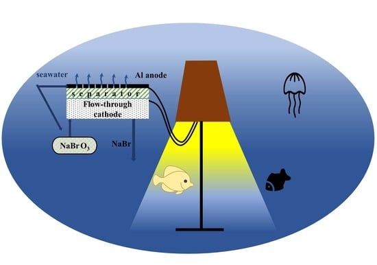
The ever-increasing characteristics of microcomputers, sensors, actuators, and communication systems require more powerful and more compact autonomous power sources. Al/bromate and Al/iodate flow batteries are proposed as new power supply units for use in oxygen-deficient environments. The batteries employ a mechanically rechargeable aluminum anode flooded with aqueous salt electrolytes or seawater, a cation-exchange membrane, and a carbonaceous porous cathode, where acidified alkali metal bromate, or iodate, is reduced in a six-electron process. The theoretical energy density of an Al/bromate flow cell per reactants is 0.65 kWh kg−1. Seawater is assumed as an electrolyte for the anode compartment. Using a H2/iodate flow cell, it is shown that iodate–iodine–iodide electrochemical transformations can be realized in both directions in acidic media at carbonaceous electrodes. At 30 °C, the area-specific power of the single cells of the Al/bromate and Al/iodate flow batteries reaches 0.26 W cm−2 and 0.075 W cm−2, respectively.

Graphical Abstract

1. Introduction

The ever-increasing characteristics of microcomputers, sensors, actuators, and communication systems require more powerful and more compact autonomous power sources. The continuously decreasing prices and increasing mass-specific and volume-specific characteristics of electronic devices have created a demand for portable power sources of cheaper prices and increasing power and energy densities [1,2,3]. The parameters of the power sources depend strongly on the area of their application. Only chemical power sources are able to meet the stringent requirements of portable electronics. Currently, and in the foreseeable future, there is no particular chemistry for power sources that satisfies all of the existing controversial criteria. Metal–air batteries are among the most powerful primary chemical power sources [4,5]. Aqueous Zn–air, Mg–air, and Al–air batteries provide high energy density coupled with safe operation. Aqueous metal–air batteries are used in safety lights, navigation buoys, and very small electronic devices, such as hearing aids. These power sources are also used as emergency power supply units. In dry states, emergency power sources of this type can be stored for years, and they are activated by the addition of aqueous electrolytes or simply water. Due to their high energy density, aqueous metal–air batteries have found their way into military applications. The high energy density of these batteries is due to the advantageous electrochemical properties of the aforementioned metals. The use of ambient oxygen as an oxidant also saves on mass and volume. A number of reviews devoted to aqueous metal–air batteries are available [6,7,8,9,10,11,12].
Of the three metals mentioned, aluminum is the most cheap, safe, and abundant. It is the second most-used metal. It is also the twelfth most-abundant element on earth. Because of its high valency in an oxidation state and its low molecular mass, Al is characterized by the very high electrochemical equivalent of 2980 Ah kg−1 compared with 3860 for lithium, 2200 for magnesium, and 820 for zinc. Al’s volumetric electrochemical equivalent is even more impressive at 8.04 Ah cm−3, compared with 2.06 for lithium, 5.85 for zinc, and 3.83 for magnesium [13,14]. These features are coupled with the high standard potential of Al in aqueous electrolytes [15], as follows:
Al → Al3+ + 3e, E0 = −1.66 V.
Electrode potentials are given versus a standard hydrogen reference electrode. In terms of volume and weight, Al is potentially among the most energy-dense anodic materials. Attempts to utilize the high standard potential of Al electrodes and its high electrochemical equivalent in chemical power sources have been hindered by the passivity of Al electrodes, and by its corrosion in aqueous electrolytes. Both the corrosion stability and mechanical properties of Al can be improved through alloying it. Pure Al is seldom used. In aqueous electrolytes electrodes of Al—or its alloys—are coated with a passivating oxide layer, which enables the use of Al as a construction metal. Because of the great practical importance of Al, the electrochemical properties of Al and its alloys have been studied in numerous works and are summarized in [15,16,17,18]. The presence of a passive layer on Al decreases its open-circuit potential and causes a “delayed action”, which is a rather long transient period during which a cell with an Al anode reaches its maximum performance [19]. An Al anode can be used in primary batteries with pH-neutral or alkaline electrolytes. In acidic electrolytes, the corrosion rate of Al is too high. pH-neutral electrolytes are advantageous due to the rather low corrosion rates of Al and the reduced hazards of these solutions compared with those of a concentrated alkali. However, in batteries with strongly alkaline electrolytes, much higher current densities can be achieved because of their higher electrolyte conductivity and the higher solubility of the aluminum hydroxide, which is the main Al oxidation product. For this reason, Al electrodes are used primarily in alkaline cells [6,20,21,22,23,24,25]. However, Al anodes have been used in batteries that utilize the electrolytes of a neutral pH—seawater, in particular [26,27].
Replacement of the air with a suitable oxidant enables the advancement of the concept of a metal–air battery for the development of cheap power sources for operation in oxygen-deficient environments. MnO2 is the first oxidant in this row [19]. Hydrogen peroxide was used as an oxidant in mechanically rechargeable batteries with aluminum anodes [21]. In [28], an Al/Cl2 semi fuel battery with a gelled aqueous salt electrolyte was demonstrated.
In our recent work, Zn/NaBrO3 and Zn/KIO3 mechanically rechargeable batteries were proposed [29]. These systems originated from our earlier work on a H2/NaBrO3 flow battery [30,31,32] in which a Pt-catalyzed hydrogen oxidation anode was coupled with a porous carbonaceous cathode at which an acidified bromate anion was reduced to bromide [33]:
3H2 = 6H+ + 6e and
BrO3 + 6H+ + 6e = Br + 3H2O       E0 = 1.41 V.
The overall chemical reaction of H2/NaBrO3 flow battery is as follows:
3H2 + BrO3 = Br + 3H2O.
Six protons for the realization of reaction (3) are provided by the hydrogen oxidation reaction in (2) and by the transport of protons through the cation-exchange membrane separating the compartments of the opposite electrodes. The autocatalytic reaction in (3) requires an acidic media to proceed. The direct path of reaction (3) is very slow. However, at potentials close to the standard potential of a bromine/bromide redox couple (5), reaction (3) is catalyzed by the formation of the intermediate product Br2, and it occurs via the following cycle [33,34]:
3Br2 + 6e → 6Br       E0 = 1.087 V and
BrO3 + 5Br + 6H+ → 3 Br2 + 3H2O.
According to [35,36], the direct reduction of the iodate to iodide is a slow process [36]:
IO3 + 6H+ + 6e = I + 3H2O       E0 = 1.14 V,
while the reaction [36]
IO3 + 6H+ + 5e = ½I2 + 3H2O   E0 = 1.19 V
is much faster. At potentials below 0.62 V, the reduction of the dissolved iodine to iodide begins as follows [37]:
I2 + 2e = 2I       E0 = 0.62 V.
The standard potential of a solid iodine reduction is only 0.535 V [37]. The proportions of iodide and iodate to regenerate I2 [35,36] are determined by:
IO3 + I +6H+ = I2 + 3H2O
Therefore, at potentials lower than the equilibrium potential of the I2/2I couple, the rate of reduction of iodate to iodide (7) is increased by the initiation of the autocatalytic cycle consisting of reactions (9) and (10), similar to the bromate reduction by reactions (5) and (6). KIO is unstable, and for this reason, its formation is not taken into consideration.
The single cells of the Zn/bromate and Zn/iodate systems consisted of a mechanically rechargeable zinc anode in contact with a neutral aqueous NaCl electrolyte, cation-exchange membrane, and carbonaceous flow through a cathode, at which the aqueous acidified halogenate was reduced. The area-specific power of the Zn/NaBrO3 single cell at 50 °C reached 0.57 W cm−2 [29].
The metal oxidation at the anode of the Zn/halogenate or Al/halogenate cell did not provide protons for the reduction of the halogenate. In this case, acid was no longer a catalyst in the halogenate reduction. It was consumed in the current generation process, and it should have been provided with a reactant flow.
In this work, we extended our research to Al/NaBrO3 and Al/KIO3 systems. Compared to Zn, Al is a more complicated anode because of the formation of a passivating layer and the poor solubility of Al corrosion products.
In the case of the Al/bromate and Al/iodate systems, the overall reactions are expressed as follows:
2Al + 6NaCl + NaBrO3 + 3H2SO4 → AlCl3 + NaBr + Na2SO4 + 3H2O
and
2Al + 6NaCl + NaIO3 + 3H2SO4 → AlCl3 + NaI + Na2SO4 + 3H2O.
It is assumed that an aluminum anode is electrochemically oxidized in aqueous NaCl and that sulphuric acid is used to acidify the catholyte. Six Na+ ions are transferred through the membrane from the anode compartment to the cathode compartment in reactions (11) and (12).
The theoretical energy density per the reactants of the Al/bromate flow battery is 0.65 kWh kg−1. The mass of the NaCl solution is not taken into account because seawater can be used as an electrolyte in an anode compartment. The primary oxidation product of Al appears to be the AlCl3 that hydrolyzes through the formation of the oxychlorides to provide virtually insoluble Al(OH)3 in pH-neutral electrolytes [38]. Particular attention is paid to the reduction of the iodate anion. Because of the poor solubility of iodine in water, the insulating layer can crystalize within the pores of the carbonaceous cathode, reducing the active area of the electrode. In this case, the iodate reduction occurs in parallel paths: a five-electron process and a six-electron process. This specific feature of the iodate reduction was mostly ignored in [29].

2. Materials and Methods

The basic experiments with the Al/halogenate flow cell were performed using a modified 5 cm2 hydrogen–air test cell from Electrochem Corp. The 5 cm2 membrane electrode assembly of the flow cell consisted of an Al anode made of expanded mesh, a Nafion cation exchange membrane, and a flow-through carbonaceous cathode. Four layers of Al 1060 (99.6% min.) expanded mesh formed the Al flow-through anode. The total thickness of the anode was 1.08 mm. The total apparent area of the electrode was higher than the working area of the counter halogenate electrode. Because of the relatively low in-plane conductivity of the ion-exchange membranes, the working area of the anode was equal to the smaller area of the carbonaceous counter electrode. The Nafion membranes NR-112, N-115, and N-117 were used to separate the compartments of the electrodes. The porous flow-through cathode comprised three layers of unteflonized TGP-H-120 Toray carbon paper with a total uncompressed thickness of 1.1 mm. It was reduced to 0.7 mm by the use of polytetrafluoroethylene (PTFE) gaskets when the flow cell was assembled. Approximately ~0.25 L of a 0.5 M NaCl solution was circulated between the vial with the electrolyte and the flow-through Al anode with the help of a peristaltic pump (BT600-2J) (Longerpump). A carbonaceous cathode was supplied with the flow acidified by the H2SO4 0.5 M NaBrO3 or 0.4 M KIO3 using a syringe pump (New Era NE-1000) or a second BT600-2J peristaltic pump. In the first case, the catholyte was passed through the cell only once. Circulation of the catholyte was arranged between a 50 mL catholyte vial and the flow cell with a peristaltic pump. In most experiments, the flow cell temperature was 30 °C. It was kept above room temperature because the high current drawn from the cell caused an increase in the cell temperature. The cell temperature was controlled by the use of a k-type thermocouple, electric cell heaters, a PID temperature controller, and a fan.
Some experiments were conducted in a standard glass electrochemical cell with three compartments separated by glass frits and a water jacket. The Ag/AgCl-KCl-saturated reference electrode was used in these experiments. The glass cell temperature was controlled by the circulation of deionized water between the thermostat (Julabo F25-MA) and a water jacket of the cell. The working compartment of the cell was purged with nitrogen gas to remove the oxygen dissolved in the electrolyte.
To gain a better understanding of the redox processes in the iodate containing the electrolytes on the carbonaceous electrode, the H2/bromate flow cell was tested. The cell arrangement was similar to that used in [30,31,32]. In this case, acidified KIO3 or KI electrolytes were pumped through the compartment with a carbonaceous electrode comprised of 3 layers of carbon paper. The counter electrode containing the Pt-catalyzed 10BC (Sigracet) gas diffusion electrode was separated from the working electrode by a Nafion N115 membrane. The hydrogen oxidation gas diffusion electrode was prepared by spray coating the catalyst ink on a gas diffusion layer with a Pt loading of 0.5 mg cm−2. More details are given in [31].
The electrochemical parameters of the cells were controlled by an ELINS P-45 potentiostat, a galvanostat, and a frequency response analyzer. The electrolytes were prepared using deionized water (6 MΩ cm) and chemicals of reagent grade. A flat Al 1060 electrode was subsequently polished with emery papers (400–800–1200) and degreased with ethanol. The hydrogen and nitrogen gases used were 99.999% pure. The Al mesh electrodes were degreased with ethanol before use.

3. Results and Discussions

3.1. Flow Cell Performance

Figure 1 shows the performance of the Al/NaBrO3 flow cell. Measurements were made at 30 °C and at 50 °C. The cell voltage was changed from an open circuit voltage (OCV) at a rate of 5 mV s−1. The anode compartment of the cell was supplied with a circulating flow of aqueous 0.5 M NaCl electrolyte at a rate of 20 mL min−1, while the cathode compartment was supplied with a circulating flow of 0.5 M NaBrO3-1 M H2SO4 electrolyte at a rate of 5 mL min−1. The OCV of the cell reached 1.9 V. In spite of the relatively low cell current density, its high voltage provided for a rather high power density of the cell. At 50 °C, the power density of the cell reached an impressive 0.36 W cm−2. At 30 °C, the maximum cell power density was 0.24 W cm−2. Compared to the H2/NaBrO3 flow cell [30,31], the power density of the Al/KBrO3 cell was ~2 times lower. The high cell voltage of the Al/KBrO3 system did not compensate for the lower current density of the cell. It appeared that the rate of the electrochemical oxidation of Al was lower than the rate of the hydrogen oxidation on the Pt-catalyzed gas diffusion electrode.
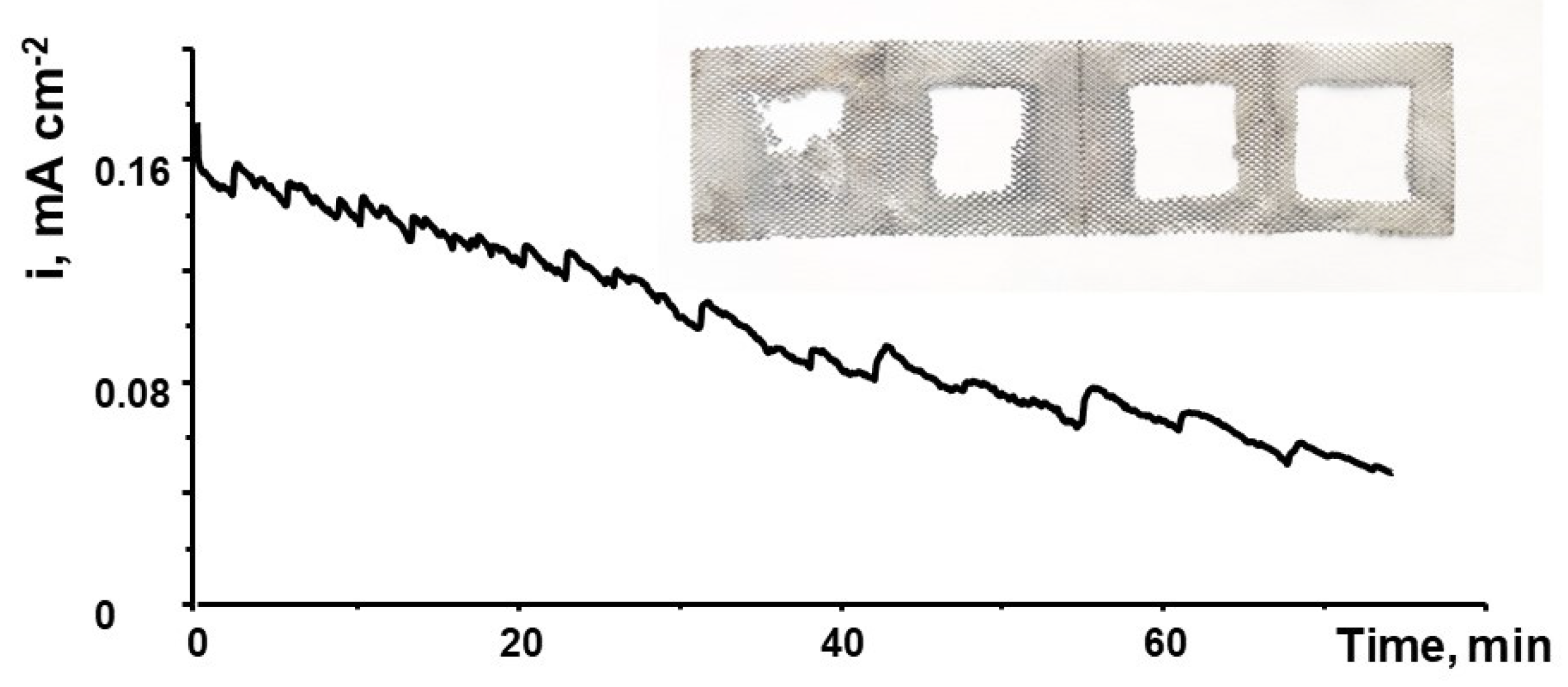
Figure 2 shows time dependence of the Al/NaBrO3 flow cell current at a constant cell voltage of E = 1.4 V. Measurements were performed under conditions similar to those of the performance measurements shown in Figure 1. The slow decrease in current density appeared to have been caused by the dissolution of the Al mesh electrode. The inset in this figure shows an image of the unfolded four-layer Al mesh electrode taken after the measurements were finished. As can be seen, the metal from the working area of the electrode was nearly completely consumed.
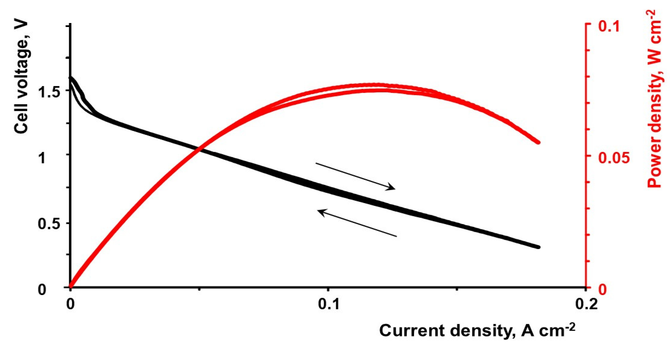
Figure 3 shows the performance of the Al/KIO3 single flow cell measured at 30 °C. The anode and cathode compartments of this cell were supplied with circulating flows of 0.4 M KIO3-1 M H2SO4 and 0.5 M NaCl electrolytes at rates of 5 and 20 mL min−1, respectively. A temperature increase of up to 50 °C did not improve the cell’s performance. The maximum power density of the cell reached only 0.075 W cm−2. The relatively poor performance of this cell appeared to have been caused by the slow electrochemical processes at both electrodes.

3.2. Electrochemical Impedance Spectroscopy Measurements

The EIS measurements of the flow cell were performed to determine if the membrane resistance influenced the flow cell’s performance. When the current was withdrawn from the cell, the Na+ cations crossed the cation exchange membrane from the anode compartment to the cathode compartment. Therefore, the membrane was in Na+ form, at least partially. The ionic conductivity of the Nafion in the Na+ form was ~7 times lower than that of the H+ form [39,40,41]. Figure 4A shows the results of the EIS measurements for the Al/NaBrO3 flow cell at an open circuit voltage using Nyquist coordinates. The high frequency intercept at the Re/Z/ axis was ~2 Ohm cm2. This is roughly twice higher than the evaluated membrane resistance of the N115 Nafion membrane in the Na+ form at ~0.9 Ohm cm2.
Similar measurements with the cells equipped with the NR-212 and N117 membranes yielded high frequency intercepts of ~1 Ohm cm2 and 3.6 Ohm cm2, respectively. The dependence of the value of the high frequency intercept on the Re/Z/ axis on the membrane thickness is shown in Figure 4B. As shown in the figure, the intercept value was roughly proportional to the cation exchange membrane’s thickness. Therefore, we concluded that the value of the intercept was indeed a measure of the membrane resistance. The induction loop in the low frequency portion of the Nyquist plot attracts attention as it is often observed in corrosion studies of metals, Al in particular [42,43,44,45,46]. The loop is typically interpreted as a manifestation of pitting corrosion.

3.3. Electrodissolution of Al in 0.5 M NaCl

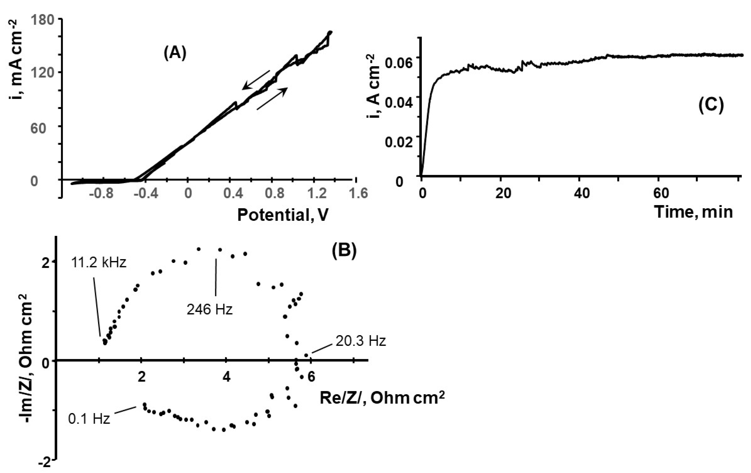
To verify that this inductive feature in the EIS spectrum of the flow cell is indeed caused by the Al dissolution process on the anode, we performed the EIS experiments with a flat Al electrode immersed in a 0.5 M NaCl electrolyte. The measurements were staged in a three-electrode, three-compartment cell. As followed from the slow scan rate voltammetry curve shown in Figure 5A, the active dissolution of the Al began at E ~ −0.45–−0.5 V, although the open circuit potential of the fresh Al electrode ranged between −0.9 and −0.75 V. According to [47,48], the sharp current increase at this potential was associated with the pitting corrosion of the Al.
Figure 5B shows the EIS spectroscopy results with a freshly polished, flat Al electrode at E = −0.4 V. The pronounced inductive loop at this figure confirmed that the inductive loop in Figure 4A was indeed caused by the corrosion of the Al anode. Figure 5C shows a flat Al dissolution current at E = −0.4 V in a 0.5 M NaCl electrolyte at 40 °C. This shows that the Al dissolution in this circulating electrolyte continued at an increasing rate. The increase in current with time was seemingly caused by the increase in the electrode–electrolyte contact area due to pitting. The weight change in the Al sample after these measurements was compared with the charge that was passed during this experiment. The sample’s weight loss corresponded only to 40% of the calculated weight loss, assuming the full dissolution of the Al in the three-electron oxidation. This indicated that a portion of the oxidized Al remained on its surface as a porous deposit. The composition of the surface oxides on the Al that corroded in the aqueous NaCl was studied by X-ray photoelectron spectroscopy in [48]. The surface film consisted primarily of Al oxides and hydroxides, with a minor inclusion of Cl ions.

3.4. Reduction of the Iodate on a Porous Carbonaceous Electrode

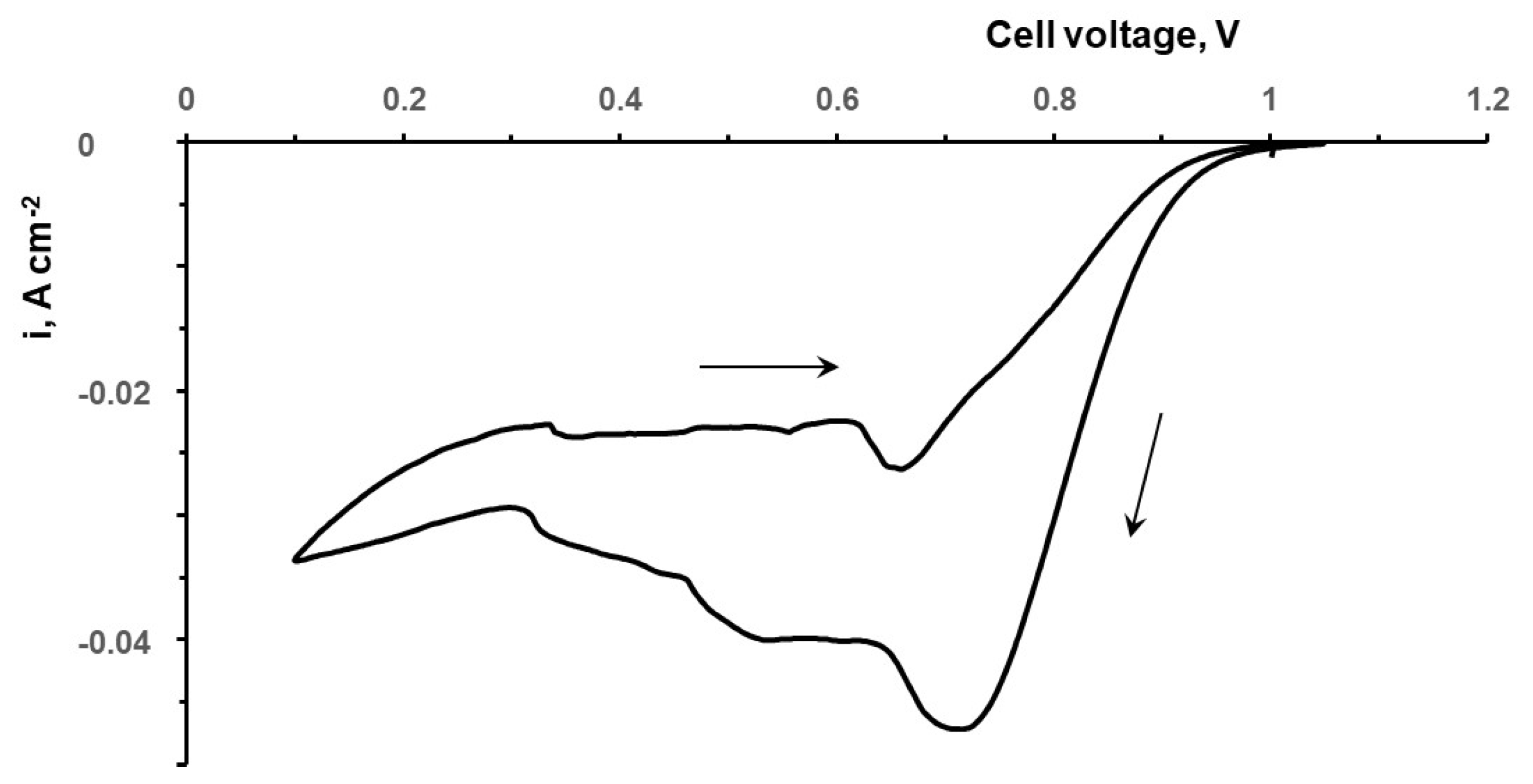
The reduction of the iodate within the porous carbonaceous electrode under conditions similar to those of the Al/iodate flow cell was staged using a H2/KIO3 flow cell. Earlier, we conducted similar research on a H2/bromate flow cell [30,31]. In the membrane electrode assembly of the Al/iodate flow cell, the Al electrode was replaced by a hydrogen oxidation gas diffusion electrode. The compartment for this electrode was supplied with hydrogen at a rate of 50 mL min−1. Because of the negligible polarization of the hydrogen gas diffusion electrode, this set up enabled the study of the processes at the carbonaceous electrode that was flooded with the KIO3-H2SO4 electrolyte. The hydrogen electrode was used as both a reference and a counter electrode. The cell voltage in this case was virtually equal to the electrode potential measured versus that of the reversible hydrogen electrode [49]. Figure 6 shows the dependence of the current on the cell voltage measured at 25 °C.
The open circuit potential of the cell was E ~ 1.06 V. It was slightly lower than the equilibrium potentials of the iodate/iodine redox couple at 1.19 V (Equation (8)) and that of the iodate/iodide couple at 1.14 V (Equation (7)). The voltammetry curve shown in Figure 6 was recorded starting at an open circuit voltage to lower the potential values at a scan rate of 2 mV s−1. It appeared that in the potential region E > 0.621 V, the equilibrium potential of the I2/I pair (Equation (9)), the iodate reduction produced mostly iodine. Iodine was partly accumulated within the pores of the carbonaceous electrode as a solid layer. Iodine was also partly removed from the pores as dissolved iodine. The balance of processes of the reduction of iodate to iodine, the deposition of the insulating layer of iodine, and removal of the dissolved iodine with the electrolyte flow determined the shape of the voltammetry curve in this potential region. At E < 0.621 V, a slow reduction of iodine to iodide provided for a nearly constant loading of the electrode with iodine. An increase in the electrolyte flow rate enabled an increase in the iodate reduction current by removing the dissolved iodine.

3.5. Iodide–Iodine–Iodate Transformations on the Carbonaceous Electrode in the Acidic Electrolytes

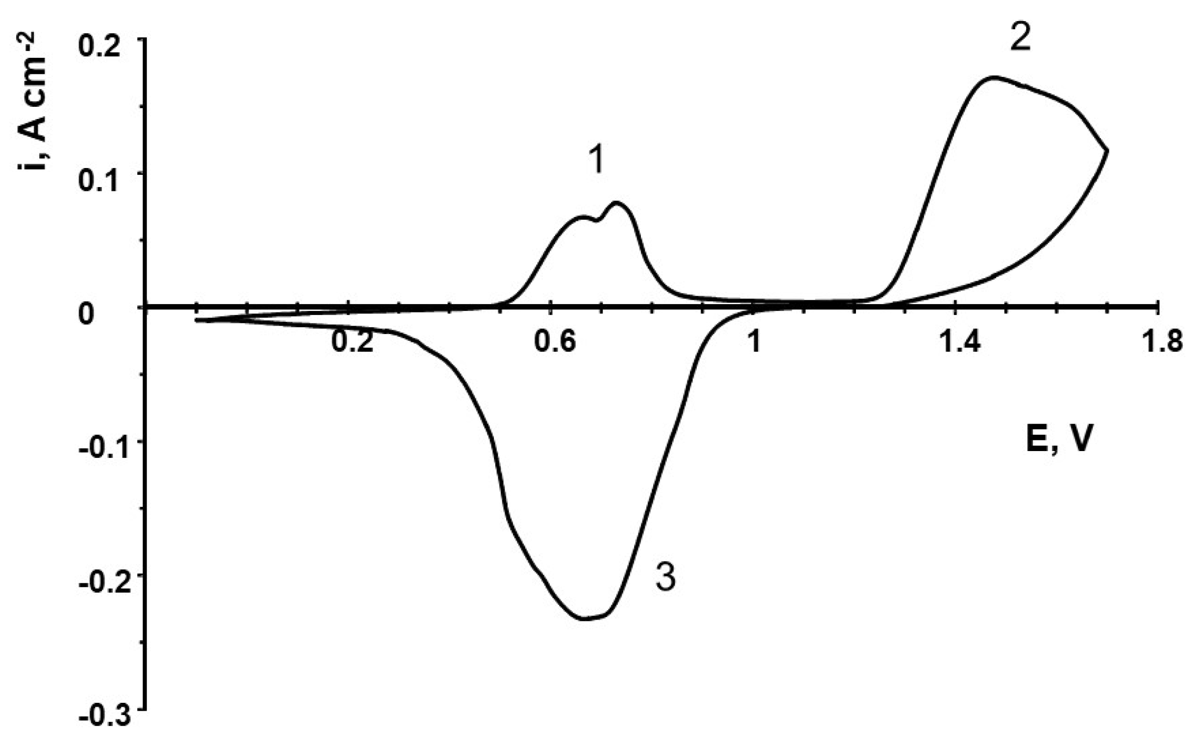
The H2/iodate flow cell that was used in the previous experiments was employed to demonstrate the reversibility of the iodide–iodine–iodate transformations. Figure 7 shows the slow scan rate of the cyclic voltammetry of the iodide–iodine–iodate transformations within the pores of the carbonaceous electrode. Prior to the measurements, the pores of the carbonaceous electrode of the flow cell were filled with 0.25 M of the KI-1 M H2SO4 electrolyte. After that, the electrolyte pumping was stopped. The Pt-catalyzed gas diffusion electrode was supplied with a continuous flow of hydrogen. At this electrode, proton reduction or hydrogen oxidation occurred close to the equilibrium potential, independent of the current direction. These reactions are known to be very fast [49]. Because the electrolyte flow was stopped, only the redox species present in the pores of the carbonaceous electrode took part in the redox processes. From the cyclic voltammetry, shown in Figure 7, it is clear that under these conditions, the reversible transformation of iodine species took place.
In Figure 7, peak (1) of the anodic current, observed on the potential scan from E = −0.1 V to the higher positive potentials, corresponds to the iodide oxidation to solid iodine and dissolved iodine. Anodic peak (2) appears to correspond to the further oxidation of iodine to iodate. On the reverse scan, broad cathodic peak (3) is observed. It appears to correspond to two reduction processes: the reduction of iodate to iodine and the subsequent reduction of iodine to iodide. Electric charges corresponding to these processes were calculated. Charges corresponding to the tailings of the peaks were taken into account. The values of the electric charges corresponding to I/I2 (peak (1)), I2/IO3 (peak (2)), and IO3/I (peak (3)) are as follows: 1.6 C cm−2, 7.2 C cm−2, and 8.7 C cm−2. The ratio between the charges is 1:4.4:5.4. This ratio is rather close to the electric charge change ratio in the iodide transformation sequence (iodide–iodine–iodate–iodide), namely, 1:5:6. This indicates that in an acidic electrolyte, electrochemical redox processes in an iodide–iodine–iodate sequence can be accomplished in both directions.

4. Conclusions

Al/bromate and Al/iodate hybrid systems are proposed as a new type of reserve and emergency power supply unit. The systems use a mechanically rechargeable Al mesh anode in contact with an aqueous salt electrolyte, a cation-exchange membrane, and a carbonaceous flow through a cathode at which aqueous acidified bromate or iodate anions are reduced to bromide or iodide in a six-electron process. The batteries have been developed as a modification of Al–air batteries for use in an environment with an absence of air. The aqueous acidified bromate or iodate solution is used as an oxidant in the battery. These batteries do not employ expensive materials or noble metals. The 5 cm2 flow cells demonstrated very promising electrochemical characteristics. The area-specific power the of Al/iodate and Al/bromate flow cells reached 0.07 and 0.23 W cm−2 at 30 °C when 0.5 M NaCl was used as an anolyte. A new multielectron oxidizer, iodate, that can be used in other electrochemical power sources, is introduced.
A H2/iodate flow cell was devised for the first time. Although its characteristics as a chemical power source are rather poor, it was successfully used to demonstrate the reversibility of iodide–iodate electrochemical transformations in an acidic electrolyte.

Author Contributions

Conceptualization, V.A. and A.A.; methodology and validation, V.A., A.A. and A.M.; experimental, A.M. All authors have read and agreed to the published version of the manuscript.

Funding

This research was funded by an RSF grant (project No 21-73-30029).

Institutional Review Board Statement

Not applicable.

Informed Consent Statement

Not applicable.

Data Availability Statement

Not applicable.

Conflicts of Interest

The authors declare no conflict of interest.

References

  1. Pantoja, W.; Perez-Taborda, J.A.; Alba Avila, A. Tug-of-War in the Selection of Materials for Battery Technologies. Batteries 2022, 8, 105. [Google Scholar] [CrossRef]
  2. Liang, Y.; Zhao, C.; Yuan, H.; Chen, Y.; Zhang, W.; Huang, J.; Yu, D.; Liu, Y.; Titirici, M.; Chueh, Y.; et al. A review of rechargeable batteries for portable electronic devices. InfoMat 2019, 1, 6–32. [Google Scholar] [CrossRef] [Green Version]
  3. Barsukov, Y.; Qian, J. Battery Power Management for Portable Devices; Artech House: Norwood, MA, USA, 2013; 241p. [Google Scholar]
  4. Rahman, M.A.; Wang, X.; Wen, C.J. High Energy Density Metal-Air Batteries: A Review. J. Electrochem. Soc. 2013, 160, A1759. [Google Scholar] [CrossRef]
  5. Wei, C.; Tan, L.; Zhang, Y.; Wang, Z.; Feng, J.; Qian, Y. Towards better Mg metal anodes in rechargeable Mg batteries: Challenges, strategies, and perspectives. Energy Storage Mater. 2022, 52, 299–319. [Google Scholar] [CrossRef]
  6. Atwater, T.B.; Dobley, A. Metal/air batteries. In Linden’s Handbook of Batteries, 4th ed.; Reddy, T.B., Linden, D., Eds.; McGraw-Hill: New York, NY, USA, 2011; Chapter 33. [Google Scholar]
  7. Arai, H. Metal Storage/metal air (Zn, Fe, Al, Mg). In Encyclopedia of Electrochemical Power Sources; Moseley, P.T., Garche, J., Eds.; Elsevier: Amsterdam, The Netherlands, 2015; pp. 337–344. [Google Scholar]
  8. Yu, J.; Li, B.-Q.; Zhao, C.-X.; Zhang, Q. Seawater electrolyte-based metal–air batteries: From strategies to applications. Energy Environ. Sci. 2020, 13, 3253–3268. [Google Scholar] [CrossRef]
  9. Liu, Q.; Pan, Z.; Wang, E.; An, L.; Sun, G. Aqueous metal-air batteries: Fundamentals and applications. Energy Storage Mater. 2020, 27, 478–505. [Google Scholar] [CrossRef]
  10. Li, L.; Chang, Z.-W.; Zhang, X.-B. Recent progress on the development of metal-air batteries. Adv. Sustain. Syst. 2017, 1, 1700036. [Google Scholar] [CrossRef]
  11. Olabi, A.G.; Sayed, E.T.; Wilberforce, T.; Jamal, A.; Alami, A.H.; Elsaid, K.; Rahman, S.M.A.; Shah, S.K.; Abdelkareem, M.A. Metal-air batteries—A review. Energies 2021, 14, 7373. [Google Scholar] [CrossRef]
  12. Han, X.; Li, X.; White, J.; Zhong, C.; Deng, Y.; Hu, W.; Ma, T. Metal–air batteries: From static to flow system. Adv. Energy Mater. 2018, 8, 1801396. [Google Scholar] [CrossRef]
  13. Binder, L. Metallic negatives. In Handbook of Battery Materials, 2nd ed.; Daniel, C., Ed.; Wiley-VCH: Weinheim, Germany, 2008; Chapter 8; Volume 2, pp. 219–238. [Google Scholar]
  14. Li, Q.; Bjerrum, N.J. Aluminum as anode for energy storage and conversion: A review. J. Power Sources 2002, 110, 1–10. [Google Scholar] [CrossRef]
  15. Franke, G.S. Thermodynamics of Electrolytic Corrosion. In Encyclopedia of Electrochemistry. Corrosion and Oxide Films; Bard, A.J., Stratmann, M., Frankel, G.S., Eds.; Wiley-VCH: Weinheim, Germany, 2003; Volume 4, pp. 9–24. [Google Scholar] [CrossRef]
  16. Vargel, C. Corrosion of Aluminium, 2nd ed.; Elsevier: Amsterdam, The Netherlands, 2020; 858p. [Google Scholar]
  17. Schütze, M.; Wieser, D.; Bender, R. (Eds.) Corrosion Resistance of Aluminium and Aluminium Alloys; Wiley-VCH: Frankfurt, Germany, 2010; 636p. [Google Scholar]
  18. Davis, J.R. (Ed.) Corrosion of Aluminum and Aluminum Alloys; ASM International: Almere, The Netherlands, 1999; 313p. [Google Scholar]
  19. Sivashanmugam, A.; Prasad, S.R.; Thirunakaran, R.; Gopukumar, S. Electrochemical Performance of Al/MnO2 Dry Cells: An Alternative to Lechlanche Dry Cells. J. Electrochem. Soc. 2008, 155, A725–A728. [Google Scholar] [CrossRef]
  20. Zaromb, S. The Use and Behavior of Aluminum Anodes in Alkaline Primary Batteries. J. Electrochem. Soc. 1962, 109, 1125–1130. [Google Scholar] [CrossRef]
  21. Hasvold, Ø.; Johansen, K.H.; Molestad, O.; Forseth, S.; Størkersen, N. The alkaline aluminium/hydrogen peroxide power source in the Hugin II unmanned underwater vehicle. J. Power Sources 1999, 80, 254–260. [Google Scholar] [CrossRef]
  22. Hasvold, Ø.; Størkersen, N.J.; Forseth, S.; Lian, T. Power sources for autonomous underwater vehicles. J. Power Sources 2006, 162, 935–942. [Google Scholar] [CrossRef]
  23. Yang, S.; Knickle, H. Design and analysis of aluminum/air battery system for electric vehicles. J. Power Sources 2002, 112, 162–173. [Google Scholar] [CrossRef]
  24. Zhang, Z.; Zuo, C.; Liu, Z.; Yu, Y.; Zuo, Y.; Song, Y. All-solid-state Al–air batteries with polymer alkaline gel electrolyte. J. Power Sources 2014, 251, 470–475. [Google Scholar] [CrossRef]
  25. Liu, Y.; Sun, Q.; Li, W.; Adair, K.R.; Li, J.; Sun, X. A comprehensive review on recent progress in aluminum-air batteries. Green Energy Environ. 2017, 2, 246–277. [Google Scholar] [CrossRef]
  26. Rao, B.M.L.; Hoge, W.H.; Zakrzewski, J.; Shah, S.; Hamlen, R.P.; Halliop, W. Aluminum-sea water battery for undersea vehicle. In Proceedings of the 6th International Symposium on Unmanned Untethered Submersible Technology, Durham, NH, USA, 12–14 June 1989. [Google Scholar] [CrossRef]
  27. Valeriote, E.M.L.; Gallop, L.D. High pressure effects on the EMF of seawater battery electrodes in chloride electrolyte. J. Electrochem. Soc. 1974, 121, 1245–1258. [Google Scholar] [CrossRef]
  28. Heise, G.W.; Schumacher, E.A.; Cahoon, N.C. A heavy duty chlorine-depolarized cell. J. Electrochem. Soc. 1948, 94, 99–105. [Google Scholar] [CrossRef]
  29. Modestov, A.D.; Andreev, V.N.; Antipov, A.E.; Petrov, M.M. Novel aqueous zinc–halogenate flow batteries as an offspring of zinc–air fuel cells for use in oxygen-deficient environment. Energy Technol. 2021, 9, 2100233. [Google Scholar] [CrossRef]
  30. Modestov, A.D.; Konev, D.V.; Tripachev, O.V.; Antipov, A.E.; Tolmachev, Y.V.; Vorotyntsev, M.A. A hydrogen–bromate flow battery for air-deficient environments. Energy Technol. 2018, 6, 242–245. [Google Scholar] [CrossRef]
  31. Modestov, A.D.; Konev, D.V.; Antipov, A.E.; Vorotyntsev, M.A. Hydrogen-bromate flow battery: Can one reach both high bromate utilization and specific power? J. Solid. State Electrochem. 2019, 23, 3075. [Google Scholar] [CrossRef]
  32. Modestov, A.; Kartashova, N.; Pichugov, R.; Petrov, M.; Antipov, A.; Abunaeva, L. Bromine crossover in operando analysis of proton exchange membranes in hydrogen−bromate flow batteries. Membranes 2022, 12, 815. [Google Scholar] [CrossRef] [PubMed]
  33. Mussini, T.; Longhi, P. Bromine. In Standard Potentials in Aqueous Solutions; Bard, A.J., Parsons, R., Jordan, J., Eds.; IUPAC: New York, NY, USA, 1985; pp. 78–84. [Google Scholar]
  34. Modestov, A.D.; Konev, D.V.; Antipov, A.E.; Petrov, M.M.; Pichugov, R.D.; Vorotyntsev, M.A. Bromate electroreduction from sulfuric acid solution at rotating disk electrode: Experimental study. Electrochim. Acta 2018, 259, 655–663. [Google Scholar] [CrossRef]
  35. Desideri, P.G. Reduction of iodate in sulphuric medium. I. Reduction mechanism. J. Electroanal. Chem. 1965, 9, 218–228. [Google Scholar] [CrossRef]
  36. Badea, G.E. Autocatalytic reduction of iodate at the platinum electrode in 0.5 M H2SO4 solutions. Rev. Roum. Chim. 2007, 52, 491–498. [Google Scholar]
  37. Vanleugenhagne, C.; Valensi, V.; Pourbaix, M. Iodine. In Atlas of Electrochemical Equilibria in Aqueous Solutions, 2nd ed.; Pourbaix, M., Ed.; NACE International and CEBELCOR: Houston, TX, USA, 1974; pp. 614–626. [Google Scholar]
  38. Xhanari, K.; Finšgar, M. Organic corrosion inhibitors for aluminum and its alloys in chloride and alkaline solutions: A review. Arab. J. Chem. 2019, 12, 4646–4663. [Google Scholar] [CrossRef]
  39. Kusoglu, A.; Weber, A.Z. New insights into perfluorinated sulfonic-acid ionomers. Chem. Rev. 2017, 117, 987–1104. [Google Scholar] [CrossRef]
  40. Hongsirikarn, K.; Goodwin, J.G., Jr.; Greenway, S.; Creager, S. Effect of cations (Na+, Ca2+, Fe3+) on the conductivity of a Nafion membrane. J. Power Sources 2010, 195, 7213–7220. [Google Scholar] [CrossRef]
  41. Basile, A. (Ed.) Handbook of Membrane Reactors: Reactor Types and Industrial Applications; Woodhead Publishing Ltd.: Sawston, UK, 2013; Volume 2, p. 407. [Google Scholar]
  42. Metikoš-Huković, M.; Babić, R.; Grubač, Z.; Brinć, S. Impedance spectroscopic study of aluminium and Al-alloys in acid solution: Inhibitory action of nitrogen containing compounds. J. Appl. Electrochem. 1994, 24, 772–778. [Google Scholar] [CrossRef]
  43. de Wit, J.H.W.; Lenderink, H.J.W. Electrochemical impedance spectroscopy as a tool to obtain mechanistic information on the passive behaviour of aluminium. Electrochim. Acta 1996, 41, 111–119. [Google Scholar] [CrossRef]
  44. Brett, C.M.A. The application of electrochemical impedance techniques to aluminium corrosion in acidic chloride solution. J. Appl. Electrochem. 1990, 20, 1000–1003. [Google Scholar] [CrossRef]
  45. Treacy, G.M.; Rudd, A.L.; Breslin, C.B. Electrochemical behaviour of aluminium in the presence of EDTA-containing chloride solutions. J. Appl. Electrochem. 2000, 30, 675–683. [Google Scholar] [CrossRef]
  46. Chen, L.; Myung, N.; Sumodjo, P.T.A.; Nobe, K. A comparative electrodissolution and localized corrosion study of 2024Al in halide media. Electrochim. Acta 1999, 44, 2751–2764. [Google Scholar] [CrossRef]
  47. Martin, F.J.; Cheek, G.T.; O’Grady, W.E.; Natishan, P.M. Impedance studies of the passive film on aluminium. Corros. Sci. 2005, 47, 3187–3201. [Google Scholar] [CrossRef]
  48. Kolics, A.; Besing, A.S.; Baradlai, P.; Haasch, R.; Wieckowski, A. Effect of pH on Thickness and Ion Content of the Oxide Film on Aluminum in NaCl Media. J. Electrochem. Soc. 2001, 148, B251–B259. [Google Scholar] [CrossRef]
  49. Wang, J.X. Hydrogen oxidation and evolution on platinum in acids. In Encyclopedia of Applied Electrochemistry; Kreysa, G., Ota, K.-I., Savinell, R.F., Eds.; Springer: New York, NY, USA, 2014. [Google Scholar] [CrossRef]
Figure 1. Performance of the Al/NaBrO3 flow cell at 30 and 50 °C.
Batteries 08 00270 g001
Figure 2. Chronoaperometric measurements at E = 1.4 V for the Al/NaBrO3 cell at 50 °C. The other conditions are the same as those in Figure 1. The inset shows a photo of the unfolded electrode removed from the cell after measurements.
Batteries 08 00270 g002
Figure 3. Performance of the Al/KIO3 single cell at 30 °C. The rates of the catholyte and anolyte supply were similar to those of the Al/NaBrO3 cell in Figure 1.
Batteries 08 00270 g003
Figure 4. (A) Results of the EIS measurements at the open circuit voltage for the Al/NaBrO3 flow cell with an NR212 membrane at 30 °C. The conditions are similar to those shown in Figure 1. (B) Dependence of the high frequency intercept at the Re/Z/ axis on the membrane thickness.
Batteries 08 00270 g004
Figure 5. (A) Voltammetry of the Al electrode at 25 °C in a 0.5 M NaCl electrolyte. A potential scan was initiated at E = −1.1 V at a scan rate of 2 mV s−1. (B) Nyquist plot of the EIS measurements with the Al electrode at E = −0.4 V in 0.5 M NaCl at 25 °C. (C) Al electrodissolution at E = −0.4 V in 0.5 M NaCl at 40 °C.
Batteries 08 00270 g005
Figure 6. Voltammetry curve measured for the H2/iodate flow cell at 25 °C. The voltage scan was initiated at an open circuit voltage at a rate of 2 mV s−1. The 0.4 M KIO3-1 M H2SO4 electrolyte was supplied at a rate of 0.1 mL min−1.
Batteries 08 00270 g006
Figure 7. Voltammetry of the H2− KI cell measured at 25 °C with a voltage scan rate of 2 mV s−1 and a H2 flow rate of 50 mL min−1. The porous carbonaceous electrode was filled with stagnant 0.25 M KI-1 M H2SO4.
Batteries 08 00270 g007
Publisher’s Note: MDPI stays neutral with regard to jurisdictional claims in published maps and institutional affiliations.