Abstract
Antimony (Sb) is regarded to be a potential alloying-type anode for lithium-ion batteries due to its excellent electrochemical reversibility and high theoretical specific capacity (660 mA h g−1). However, huge volume expansion accompanying rapid capacity fading seriously hinders its commercial application. Herein, double-carbon-modified spindle-structured Sb@C@NC were constructed via galvanic replacement using a Fe-based metal-organic framework (MOF) with polydopamine-coated-derived Fe@C@NC as reactants. Due to the unique double-carbon-encapsulated structure, the Sb@C@NC anode effectively moderates the volume fluctuation and maintains the integral framework from collapsing during the annealing and cycling process. As lithium-ion battery (LIB) anodes, Sb@C@NC attained excellent cycling performance (389 mAh g−1 at 100 mA g−1 after 100 cycles) and superior rate capability (a reversible capacity of 343 mAh g−1 at 2000 mA g−1). Such an MOF-based approach provides an adjustable strategy for Sb-based nanomaterial and shield light on the applications of Sb@C@NC in other fields.
1. Introduction
Lithium-ion batteries (LIBs) have been widely applied in commercial electronic devices (smartphones, laptops, etc.) and electric vehicles in recent years owing to their exceptional energy density and long cycle life [1,2,3]. However, for the wider application of LIBs, it is necessary to spare no effort to boost their energy density and improve their cycle life. Graphite, a widely used anode, because of its low theoretical specific capacity (372 mAh g−1) and inferior safety problems (0.1 V vs. Li/Li+), has gradually failed to meet the requirements for high-energy density LIBs. Therefore, researchers have focused on discovering and designing various anode materials to replace traditional graphite. Antimony (Sb), with a high specific capacity (660 mAh g−1) and safe intercalation potential (0.8 V vs. Li/Li+), is the most promising anode for next-generation high-energy LIBs [4,5,6,7,8,9]. However, current Sb-based anodes undergo large volume variation (over 150% volume increase via the formation of Li3Sb) during the charge–discharge process, which inhibits the practical application of Sb anodes in LIBs. Furthermore, such a huge volume expansion causes the serious cracking of the active materials and an unstable solid electrolyte interphase (SEI), resulting in a rapid decrease in specific capacity and a short cycle life [10,11,12,13,14]. Therefore, to inhibit volume expansion, various researchers focused their attention on designing Sb-based alloys with Sn, Zn, Bi, Ni, Co, Cu, and other metallic elements [15,16,17,18,19,20,21], and combined with conductive carbon materials [10,22,23,24,25,26,27,28,29,30,31]. In detail, the introduction of metallic elements, especially nonelectroactive elements with relatively high atomic mass, provides a buffer for the volume variation, but decreases the integral energy density. However, the carbon-coating layer not only buffers the volume variation of Sb during the charge and discharge process, but also provides additional sites for the insertion of lithium ions. At the same time, the addition of nitrogen-doped carbon (NC) can introduce defects and improve electronic conductivity [32,33,34]. Dopamine, a special small organic molecule, can self-polymerize onto the surface of active materials in a particular solution, forming a uniform polydopamine (PDA) coating layer, and then pyrolyze to form a uniform N-doped carbon-coated shell. With the inertness of the original bulk generating poor Li+ diffusion kinetics, designing nanostructured Sb electrodes is a feasible method to settle these issues. Metal–organic-framework MOFs are porous materials formed by metal-ion and organic ligands through self-assembly and coordination bond linkage, which were first defined by Yaghi et al. [35] in the 1990s, have recently attracted considerable attention. Numerous studies showed that MOFs can combine metallic elements with a carbon framework, which is an effective strategy to encapsulate active materials into a conductive network and confine the growth of active materials. Facile galvanic replacement was also confirmed as an effective strategy for synthesizing nanomaterials and preventing the growth of active particles [36,37].
Herein, we chose Fe-MOF as the precursor, and coated it with polydopamine annealing in the Ar atmosphere to attain the nitrogen-doped carbon and MOF-derived carbon-encapsulated Fe nanocomposite (Fe@C@NC). Double-carbon-modified Sb@C@NC was obtained via a facile galvanic replacement of Fe@C@NC in an SbCl3 solution. Benefiting from the special double-carbon-modified nanorod design, this Sb@C@NC anode attained 389 mA h g−1 after 100 cycles at 100 mA g−1 and possessed a specific capacity of 343 mA h g−1 at 2000 mA g−1. This strategy broadens the avenue for designing carbon-encapsulated Sb-based anodes for LIBs.
2. Results and Discussion
Figure 1 shows the detailed construction process of the double-carbon-encapsulated Sb@C@NC anodes. First, Fe-MOF was prepared via hydrothermal reaction by dissolving an appropriate proportion of fumaric acid (FA) and Fe(NO3)3 in an N,N-dimethylformamide (DMF) solution and maintained at 110 °C for 1 h. The robust spindle-structured Fe-MOF precipitates were washed, filtered, and collected. Then, Fe-MOF and dopamine were mixed and stirred in a weak alkaline water solution for 20 h to obtain Fe-MOF@polydopamine (Fe-MOF@PDA). After that, Fe-MOF@PDA was treated in 5 vol% H2/Ar mixture gases at 600 °C for 2 h to obtain the spindle-structured Fe@C@NC. Lastly, Sb@C@NC anodes were synthesized via a galvanic replacement process of Fe@C@NC using an excess SbCl3 ethanol solution at 100 °C for 24 h (Fe + Sb3+ → Sb + Fe3+). The synthesized Sb@C@NC completely inherited the structure of Fe-MOF, and the dopamine coating could also keep the structure stable and avoid the precipitation of metallic Fe during the pyrolytic process.
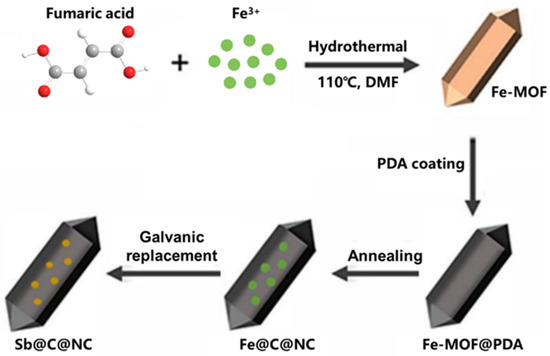
Figure 1.
Schematic illustration of the preparation process of Sb@C@NC.
The microstructure of the Fe-MOF, Fe@C, Fe@C@NC, Sb@C, and Sb@C@NC was characterized with scan electron microscopy (SEM). Figure 2a,b show the SEM images of Fe-MOF, which displayed robust spindle-structured structures. Figure 2b shows the high-magnification SEM image of Fe-MOF, which demonstrates that the middle part of the Fe-MOF was a prism structure, and two terminals were cone-shaped. The SEM results reveal that the length and width of the Fe-MOF were about 800 and 250 nm, respectively. Figure S1 (Supplementary Materials) and Figure 2c,d are the SEM results of the Fe@C and Fe@C@NC, respectively. Figure S1 demonstrates that the Fe@C maintained a nanorod structure that was similar to the morphology of Fe-MOF. The high-magnification result (Figure S1b) shows that the surface of the Fe@C nanorods was rough and accompanied by the aggregation of nanoparticles. Therefore, to inherit the spindle structure of Fe-MOF well, PDA was in situ polymerized on the surface of Fe-MOF and then pyrolyzed to form a double-layer coating. Figure 2c,d show the well-preserved Fe@C@NC spindle structure of Fe-MOF, which was composed of prisms and cones, and the size of Fe@C@NC, which were well-consistent with the Fe-MOF. The above SEM results reveal that the structure of Fe-MOF was well-inherited during the pyrolytic procedure by coating with PDA. Figure S2 (Supplementary Materials), and Figure 2e,f, exhibit the morphology of the Sb@C and Sb@C@NC after galvanic replacement. The morphology was without obvious change during the galvanic replacement process. Different from Sb@C, the structure of Sb@C@NC retained the spindle-structured Fe-MOF, which further reveals that the double-carbon modification enhanced the integral structure stability well.
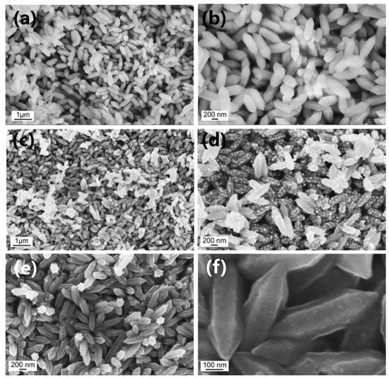
Figure 2.
Low- and high-magnification SEM results of (a,b) Fe-MOF, (c,d) Fe@C@NC, and (e,f) Sb@C@NC.
Figure 3a shows the X-ray diffraction (XRD) patterns of the double-carbon-modified Fe@C@NC ;the main diffraction peaks were well-confirmed to the metallic Fe (JCPDS bo. 65-4899), and the other diffraction peaks were matched with the pure Fe3C (JCPDS no. 34-0001). The XRD results reveal that most of the Fe3+ were reduced to elemental Fe, with a small part forming the carbide Fe3C during the annealing procedure. Figure 3b exhibits the XRD pattern of the final product, Sb@C@NC, and all the diffraction peaks were well-confirmed to pure Sb (JCPDS no. 85-1322), which demonstrates that the galvanic replacement could completely transform Fe into pure Sb. The existence of Fe3C cannot be observed in Figure 3b. The XRD results of pure Fe3C before and after the reaction in the SbCl3 solution (Figure S3, Supplementary Materials) show that the Fe3C may not undergo galvanic replacement with Sb3+, but the weak peak strength indicate that the Fe3C may have partly been dissolved in the SbCl3 solution. This phenomenon may explain why no peaks of Fe3C exist in the final Sb@C@NC sample. In order to determine the carbon content in the Sb@C and Sb@C@NC materials, the samples were measured via thermogravimetric analysis (TGA). As depicted in Figure 3c, the green and yellow TG curves correspond to Sb@C@NC and Sb@C, respectively. The TG curves show that the first weight loss from 40 to ~200 °C was due to the loss of the moisture or water of crystallization, and the weight gain corresponded to the oxidation of elemental Sb (the weight gain for complete oxidation of pure Sb was 16.4%). The second weight loss was attributed to the combustion of carbon materials to CO2 and was accomplished with the oxidation of elemental Sb to Sb2O3 [38]. On the basis of the above results, the carbon content in these samples was 20.8 and 35.9 wt. % for Sb@C and Sb@C@NC, respectively. Figure 3d is the result of the Raman spectrum in which the intrinsic peaks of graphene at about 1335 and 1592 cm−1 can be clearly observed. The peak of the D band (at 1335 cm−1) was due to the disorder of the sample or the edges of graphene or disorder samples, while the peak of the G band (at 1592 cm−1) originated from the scattering of sp2 carbon domains [39].
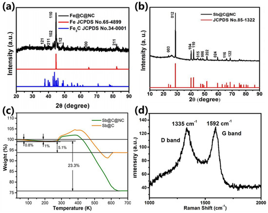
Figure 3.
XRD results of (a) Fe@C@NC and (b) Sb@C@NC; (c) TG curves of Sb@C and Sb@C@NC. (d) Raman spectrum of Sb@C@NC.
The microstructure of the robust spindle-structured Sb@C@NC anodes was further characterized via transmission electron microscopy (TEM). As depicted in Figure 4a,b, the prepared Sb@C@NC preserved a spindlelike structure with uniform size. In addition, the existence of porous carbon could be observed at the edge position of the spindle-structured Sb@C@NC, which originated from the pyrolysis of Fe-MOF and PDA. The high-angle annular dark-filed (HAADF) TEM signal (Figure 4c) further certified the Sb@C@NC with a spindle structure feature that consisted of a porous carbon framework or Sb nanoparticles. In addition, the energy-dispersive spectrometer (EDS) results of the Sb@C@NC are shown in Figure 4d–f, which verified the uniform distribution of N, Sb, and C elements with a spindle structure. Benefiting from the polydopamine (PDA) coating strategy, the carbon shell was doped with nitrogen. All the results indicate that Sb@C@NC with a spindle structure was successfully prepared via a metal–organic framework-derived route followed by PDA coating and galvanic replacement.
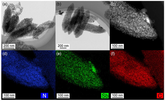
Figure 4.
(a,b) TEM images of Sb@C@NC. (c) HAADF TEM image. (d–f) TEM EDS element mapping signals of Sb@C@NC.
Figure 5a exhibits the cyclic voltammetry (CV) curses of Sb@C@NC anodes at the scan rate of 0.1 mV s−1 between the potential (V) of 0.01 and 2 V. Except for the initial discharging process, there was only one sharp oxidation and reduction peak in the rest of the charge and discharge processes, which indicates that the Sb@C@NC anodes had a simple insertion/desertion process [1]. A sharp reduction peak at 0.75 V and a broad reduction peak at 1.53 V appeared during the first discharge. The reduction peak at 1.53 V was the result of the activation of Sb@C@NC and the formation of a solid electrolyte interphase (SEI) during the initial lithiation procedure. The lithiation process could be summarized as the following reaction:
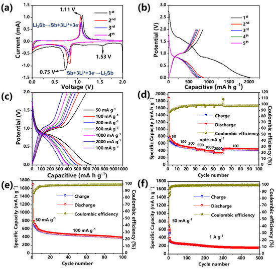
Figure 5.
Lithium-ion storage properties of Sb@C@NC: (a) CV curves at 0.1 mV s−1. (b) Discharge–charge profiles at 100 mA g−1. (c) Discharge–charge profiles at various rates. (d) Rate capability. (e) Cycling performance at 100 mA g−1. (f) Cycling performance at 1 A g−1.
In the subsequent charging process, an oxidation peak was shown at 1.11 V that benefited from the desertion of Li+. The reaction formula is as follows [38,40]:
During the next four discharging processes, the reduction peak shifted to 0.81 V, while the reduction peak at 1.53 V disappeared. In addition, during the second lithiation process, the strength of the reduction peak was significantly larger than that of the subsequent few cycles because of the considerable carbon content in the Sb@C@NC, resulting in many irreversible capacity losses. The discharge–charge profiles were almost overlapped in subsequent cycles, which reveals that the Sb@C@NC anode had good cycling reversibility for LIBs. The Sb@C@NC anodes still exhibited a reversible specific capacity of 389 mA h g−1 at 100 cycles, yielding a Coulombic efficiency of 99%, while Sb@C anodes just showed a reversible specific capacity of 237 mA h g−1 (Figure S4b, Supplementary Materials). Figure 5b shows the charge–discharge curves of Sb@C@NC anodes during the activation process at 50 mA g−1. Moreover, a discharge voltage platform appeared at 0.75 V, which was matched with the results of the CV test (Figure 5a). During the following four charge–discharge cycles, the curves overlapped with each other, indicating good reversibility. Figure 5c,d shows the rate capability of Sb@C@NC anodes. In Figure 5d, when the current density increased continuously, the reversible capacity of the materials decreased slowly. Cycling at 50, 100, 200, 500, 1000, and 2000 mA g−1, the Sb@C@NC attained specific capacities of 558, 517, 478, 432, 387, and 339 mAh g−1, respectively. Especially when reduced to 100 mA g−1, the anodes still had a reversible specific capacity of 451 mA h g−1. By contrast, Sb@C anodes exhibited 592, 512, 391, 295, 242, and 202 mA h g−1 at 50, 100, 200, 500, 1000, and 2000 mA g−1, respectively (Figure S4b, Supplementary Materials). Figure 5c shows the discharge–charge curves of the Sb@C@NC anodes at different current densities. The charge–discharge profiles had similar shapes at different current densities. When increased to 2000 mA g−1, a flat voltage platform could still be observed in the charge–discharge profiles without significant change. Figure 5e shows that the initial coulombic efficiency (ICE) was about 45.1%, which was due to the large specific surface area of the Sb@C@NC anodes and the high carbon content of the material, so there was a large number of irreversible SEI formations during the first cycle. Meanwhile, from the results of the CV curves (Figure 5a), the capacity contribution below 0.5 V was mainly from the carbon contribution, while the capacity above 0.5 V was occupied by the alloying/dealloying of Sb particles. So, we could divide the capacity into different voltage regions (0.5–3.0 and 0.01–0.5 V), and the results are summarized in Figure S5 (Supplementary Materials). The specific capacity contribution fraction of Sb for the Sb@C@NC composites decreased more slowly over the whole cycling, which proved that double carbon coating could indeed aid in the cycling stability of Sb particles. Figure 5f shows the cycling performance of the Sb@C@NC anodes at 1 A g−1. The Sb@C@NC anode showed an initial specific capacity of 342.6 mAh g−1, 204.0 mAh g−1 after 200 cycles, and still had a reversible specific capacity of 160.0 mAh g−1 after 500 cycles. Moreover, the cycling performance of Sb@C@NC anodes with higher loading (3.2 mg cm−2) was tested and is exhibited in Figure S6 (Supplementary Materials). This Sb@C@NC attained a reversible specific capacity of 261.2 mAh g−1 at 1 A g−1. The results fully reveal that the spindle-structured Sb@C@NC anodes exhibited good cycling stability for LIBs. Furthermore, the Sb@C@NC anodes also exhibited excellent rate capability in sodium-ion batteries (Figures S7 and S8, Supplementary Materials) due to their high carbon content. Above all, these results fully reveal that the spindle-structured Sb@C@NC anode possessed exceptional cycling and rate capabilities.
To further investigate the origin of the superior rate capability of the spindle-structured Sb@C@NC anodes, CV measurements at different scan rates were performed. In Figure 6a, the CV profiles at 0.2, 0.4, 0.7, 1.0, and 1.5 mV s−1 have a well-overlapped shape. Figure 6b shows the relationship between the scan rate (logv) and peak current (logi) of the Sb@C@NC anode, which can be defined as follows [41,42]:
where a and b are empirical parameters. Normally, the b-value is equal to 0.5, representing that the charging and discharging process is completely controlled by diffusion, and the b-value is 1 representing a capacitance-dominated process. As shown in Figure 5b, the b-values of anodic and cathodic peaks were 0.595 and 0.505, respectively; both were over 0.5, indicating fast kinetics owing to the pseudocapacitive effect. Figure 6c and Figure S9 (Supplementary Materials) exhibit the capacitive contribution (the blue curves) and the total current contribution (the red area). The ratios of pseudocapacitive contribution (Figure 6d) were 37.6%, 53.8%, 62.0%, 69.3%, 74.4%, and 79.7% at the scan rates of 0.1, 0.2, 0.4, 0.7, 1.0 and 1.5 mV s−1, respectively, which reveals that the pseudocapacitive effect occupied a high ratio to the total capacity [41]. Lastly, the rate capability of the current spindle-structured Sb@C@NC with other previously designed Sb-based materials for LIBs is simply summarized in Table S1. The current spindle-structured Sb@C@NC anode also emerged with distinct superiority in specific capacity and cycling capability [43,44,45,46,47,48,49]. The advantages of these spindle-structured Sb@C@NC can be summarized as follows: the unique porous spindle-structured structure of Sb@C@NC endows sufficient interspace to inhibit the volume fluctuations while the ions reciprocate insertion/desertion. Moreover, the Sb@C@NC anodes with porous features favor the infiltration of electrolytes, and boost electron and ion transportation. Lastly, the double-carbon-modified framework can effectively improve electrical conductivity and maintain structural stability, thereby achieving good electrochemical properties.
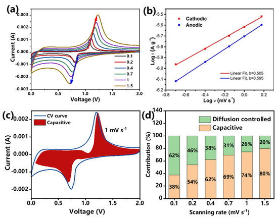
Figure 6.
Kinetic analysis of Sb@C@NC: (a) CV curves at different scan rates. (b) Relationship between peak current and scan rates. (c) Pseudocapacitive contribution at 1.0 mV s−1. (d) Pseudocapacitive contribution ratio of capacitive summarized from 0.1 to 1.5 mV s−1.
3. Conclusions
In summary, a robust spindle-structured Sb@C@NC anode was successfully fabricated via a metal–organic-framework-derived route, followed by PDA coating and galvanic replacement. For LIBs, the Sb@C@NC exhibited exceptional lithium-ion storage performance. This Sb@C@NC anode achieved an ICE of 45.1%, and cycling at 50, 100, 200, 500, 1000, and 2000 mA g−1 attained a reversible specific capacity of 698, 536, 492, 438, 393, and 343 mAh g−1, respectively. Furthermore, the Sb@C@NC anodes also exhibited excellent rate capability in SIBs (sodium-ion batteries). The excellent electrochemical properties of Sb@C@NC possessed can be ascribed to the unique double-carbon-coated spindle-structured feature, which could significantly moderate the volume fluctuation and avoid the irreversible agglomeration of active Sb nanoparticles, thus improving the electrochemical reaction kinetics, and possessing superior cycling performance and rate capability. This galvanic replacement route and MOF-derived strategy open a window to designing double-carbon-modified nanomaterials for alkali-ion storage devices.
Supplementary Materials
The following supporting information can be downloaded at: https://www.mdpi.com/article/10.3390/batteries8110245/s1. Figure S1: (a) Low- and (b) high-magnification SEM images of Fe@C; Figure S2: SEM results of Sb@C; Figure S3: XRD pattern of Fe3C and Fe3C with galvanic replacement; Figure S4: (a) Cyclic performance of Sb@C at 100 mA g−1. (b) Rate capability of Sb@C; Figure S5: Specific capacity contribution of carbon and Sb for the Sb@C and Sb@C@NC composites; Figure S6: Cyclic performance of Sb@C@NC anodes with a high loading of 3.2 mg cm−2 at 1 A g−1; Figure S7: Cyclic performance of Sb@C at 100 mA g−1 for SIBs; Figure S8: (a) Cyclic performance of Sb@C@NC at 100 mA g−1 for SIBs. (b) Rate capability of Sb@C@NC for SIBs; Figure S9: Capacitive capacity contribution to the total current contribution at (a) 0.1 mV s−1, (b) 0.2 mV s−1, (c) 0.4 mV s−1, (d) 0.7 mV s−1, and (e) 1.5 mV s−1; Table S1: Comparison of the rate performance of Sb@C@NC with various Sb-based anode materials.
Author Contributions
Conceptualization, J.L. (Junhao Liu) and P.L.; methodology, P.L.; formal analysis, J.L. (Junhao Liu) and P.L.; investigation, J.L. (Junhao Liu) and X.X.; resources, J.L. (Junhao Liu) and X.X.; writing—original draft preparation, J.L. (Jun Liu); writing—review and editing, F.L., Z.L., P.L., J.L. (Jun Liu) and X.X.; visualization, J.L. (Junhao Liu) and P.L.; supervision, J.L. (Jun Liu) and X.X.; project administration, J.L. (Jun Liu) and X.X.; funding acquisition, J.L. (Jun Liu) and X.X. All authors have read and agreed to the published version of the manuscript.
Funding
This work was funded by the Guangdong Pearl River Talents Plan (no. 2017GC010218), the Guangdong Basic and Applied Basic Research Foundation (nos. 2020B1515120049 and 2021A1515010153), and the R&D Program in Key Areas of Guangdong Province (no. 2020B0101030005).
Data Availability Statement
The data presented in this study are available on request from the corresponding author.
Conflicts of Interest
The authors declare no conflict of interest.
References
- Wang, B.; Deng, Z.; Xia, Y.; Hu, J.; Li, H.; Wu, H.; Zhang, Q.; Zhang, Y.; Liu, H.; Dou, S. Realizing Reversible Conversion-Alloying of Sb(V) in Polyantimonic Acid for Fast and Durable Lithium- and Potassium-Ion Storage. Adv. Energy Mater. 2019, 10, 1903119. [Google Scholar] [CrossRef]
- Ge, M.; Cao, C.; Biesold, G.M.; Sewell, C.D.; Hao, S.M.; Huang, J.; Zhang, W.; Lai, Y.; Lin, Z. Recent Advances in Silicon-Based Electrodes: From Fundamental Research toward Practical Applications. Adv. Mater. 2021, 33, e2004577. [Google Scholar] [CrossRef]
- Li, P.; Yu, L.; Ji, S.; Xu, X.; Liu, Z.; Liu, J.; Liu, J. Facile Synthesis of Three-Dimensional Porous Interconnected Carbon Matrix Embedded with Sb Nanoparticles as Superior Anode for Na-ion Batteries. Chem. Eng. J. 2019, 374, 502–510. [Google Scholar] [CrossRef]
- Yousaf, M.; Wang, Y.; Chen, Y.; Wang, Z.; Firdous, A.; Ali, Z.; Mahmood, N.; Zou, R.; Guo, S.; Han, R.P.S. A 3D Trilayered CNT/MoSe2/C Heterostructure with an Expanded MoSe2 Interlayer Spacing for an Efficient Sodium Storage. Adv. Energy Mater. 2019, 9, 1900567. [Google Scholar] [CrossRef]
- Yin, H.; Li, Q.; Cao, M.; Zhang, W.; Zhao, H.; Li, C.; Huo, K.; Zhu, M. Nanosized-bismuth-embedded 1D Carbon Nanofibers as High-performance Anodes for Lithium-ion and Sodium-ion Batteries. Nano Res. 2017, 10, 2156–2167. [Google Scholar] [CrossRef]
- Wang, N.; Bai, Z.; Qian, Y.; Yang, J. Double-Walled Sb@TiO2-x Nanotubes as a Superior High-Rate and Ultralong-Lifespan Anode Material for Na-Ion and Li-Ion Batteries. Adv. Mater. 2016, 28, 4126–4133. [Google Scholar] [CrossRef]
- Sultana, I.; Rahman, M.M.; Chen, Y.; Glushenkov, A.M. Potassium-Ion Battery Anode Materials Operating through the Alloying-Dealloying Reaction Mechanism. Adv. Funct. Mater. 2018, 28, 1703857. [Google Scholar] [CrossRef]
- Nitta, N.; Yushin, G. High-Capacity Anode Materials for Lithium-Ion Batteries: Choice of Elements and Structures for Active Particles. Part. Part. Syst. Charact. 2014, 31, 317–336. [Google Scholar] [CrossRef]
- Liu, S.; Feng, J.; Bian, X.; Liu, J.; Xu, H. The Morphology-controlled Synthesis of a Nanoporous-antimony Anode for High-performance Sodium-ion Batteries. Energy Environ. Sci. 2016, 9, 1229–1236. [Google Scholar] [CrossRef]
- Liu, J.; Yu, L.; Wu, C.; Wen, Y.; Yin, K.; Chiang, F.-K.; Hu, R.; Liu, J.; Sun, L.; Gu, L.; et al. New Nanoconfined Galvanic Replacement Synthesis of Hollow Sb@C Yolk-Shell Spheres Constituting a Stable Anode for High-Rate Li/Na-Ion Batteries. Nano Lett. 2017, 17, 2034–2042. [Google Scholar] [CrossRef]
- Liang, L.; Xu, Y.; Wang, C.; Wen, L.; Fang, Y.; Mi, Y.; Zhou, M.; Zhao, H.; Lei, Y. Large-scale Highly Ordered Sb Nanorod Array Anodes with High Capacity and Rate Capability for Sodium-ion Batteries. Energy Environ. Sci. 2015, 8, 2954–2962. [Google Scholar] [CrossRef]
- Lao, M.; Zhang, Y.; Luo, W.; Yan, Q.; Sun, W.; Dou, S.X. Alloy-Based Anode Materials toward Advanced Sodium-Ion Batteries. Adv. Mater. 2017, 29, 1700622. [Google Scholar] [CrossRef] [PubMed]
- He, M.; Kraychyk, K.; Walter, M.; Kovalenko, M.V. Monodisperse Antimony Nanocrystals for High-Rate Li-ion and Na-ion Battery Anodes: Nano versus Bulk. Nano Lett. 2014, 14, 1255–1262. [Google Scholar] [CrossRef] [PubMed]
- Darwiche, A.; Marino, C.; Sougrati, M.T.; Fraisse, B.; Stievano, L.; Monconduit, L. Better Cycling Performances of Bulk Sb in Na-Ion Batteries Compared to Li-Ion Systems: An Unexpected Electrochemical Mechanism. J. Am. Chem. Soc. 2012, 134, 20805–20811. [Google Scholar] [CrossRef]
- He, M.; Walter, M.; Kravchyk, K.V.; Erni, R.; Widmer, R.; Kovalenko, M.V. Monodisperse SnSb Nanocrystals for Li-ion and Na-ion Battery Anodes: Synergy and Dissonance Between Sn and Sb. Nanoscale 2015, 7, 455–459. [Google Scholar] [CrossRef] [PubMed]
- Liu, J.; Yang, Z.; Wang, J.; Gu, L.; Maier, J.; Yu, Y. Three-dimensionally Interconnected Nickel-antimony Intermetallic Hollow Nanospheres as Anode Material for High-rate Sodium-ion Batteries. Nano Energy 2015, 16, 389–398. [Google Scholar] [CrossRef]
- Li, J.; Pu, J.; Liu, Z.; Wang, J.; Wu, W.; Zhang, H.; Ma, H. Porous-Nickel-Scaffolded Tin-Antimony Anodes with Enhanced Electrochemical Properties for Li/Na-Ion Batteries. ACS Appl. Mater. Interfaces 2017, 9, 25250–25256. [Google Scholar] [CrossRef]
- Wang, L.; Wang, C.; Zhang, N.; Li, F.; Cheng, F.; Chen, J. High Anode Performance of in Situ Formed Cu2Sb Nanoparticles Integrated on Cu Foil via Replacement Reaction for Sodium-Ion Batteries. ACS Energy Lett. 2017, 2, 256–262. [Google Scholar] [CrossRef]
- Wang, N.; Bai, Z.; Qian, Y.; Yang, J. One-Dimensional Yolk-Shell Sb@Ti-O-P Nanostructures as a High-Capacity and High-Rate Anode Material for Sodium Ion Batteries. ACS Appl. Mater. Interfaces 2017, 9, 447–454. [Google Scholar] [CrossRef]
- Xie, H.; Kalisvaart, W.P.; Olsen, B.C.; Luber, E.J.; Mitlin, D.; Buriak, J.M. Sn-Bi-Sb Alloys as Anode Materials for Sodium Ion Batteries. J. Mater. Chem. A 2017, 5, 9661–9670. [Google Scholar] [CrossRef]
- Yu, L.; Zhang, L.; Fu, J.; Yun, J.; Kim, K.H. Hierarchical Tiny-Sb Encapsulated in MOFs Derived-carbon and TiO2 Hollow Nanotubes for Enhanced Li/Na-Ion Half-and Full-cell batteries. Chem. Eng. J. 2021, 417, 129106. [Google Scholar] [CrossRef]
- Ding, Y.-L.; Wu, C.; Kopold, P.; van Aken, P.A.; Maier, J.; Yu, Y. Graphene-Protected 3D Sb-based Anodes Fabricated via Electrostatic Assembly and Confinement Replacement for Enhanced Lithium and Sodium Storage. Small 2015, 11, 6026–6035. [Google Scholar] [CrossRef] [PubMed]
- Wu, L.; Lu, H.; Xiao, L.; Ai, X.; Yang, H.; Cao, Y. Electrochemical Properties and Morphological Evolution of Pitaya-like Sb@C Microspheres as High-performance Anode for Sodium Ion Batteries. J. Mater. Chem. A 2015, 3, 5708–5713. [Google Scholar] [CrossRef]
- Qiu, S.; Wu, X.; Xiao, L.; Ai, X.; Yang, H.; Cao, Y. Antimony Nanocrystals Encapsulated in Carbon Microspheres Synthesized by a Facile Self-Catalyzing Solvothermal Method for High-Performance Sodium-Ion Battery Anodes. ACS Appl. Mater. Interfaces 2016, 8, 1337–1343. [Google Scholar] [CrossRef]
- Zhou, S.; Chen, J.; Gan, L.; Zhang, Q.; Zheng, Z.; Li, H.; Zhai, T. Scalable Production of Self-supported WS2/CNFs by Electrospinning as the Anode for High-performance Lithium-ion Batteries. Sci. Bull. 2016, 61, 227–235. [Google Scholar] [CrossRef][Green Version]
- Wu, T.; Hou, H.; Zhang, C.; Ge, P.; Huang, Z.; Jing, M.; Qiu, X.; Ji, X. Antimony Anchored with Nitrogen-Doping Porous Carbon as a High-Performance Anode Material for Na-Ion Batteries. ACS Appl. Mater. Interfaces 2017, 9, 26118–26125. [Google Scholar] [CrossRef]
- Xu, X.; Dou, Z.; Gu, E.; Si, L.; Zhou, X.; Bao, J. Uniformly-distributed Sb Nanoparticles in Ionic Liquid-derived Nitrogen-enriched Carbon for Highly Reversible Sodium Storage. J. Mater. Chem. A 2017, 5, 13411–13420. [Google Scholar] [CrossRef]
- Yang, Q.; Zhou, J.; Zhang, G.; Guo, C.; Li, M.; Zhu, Y.; Qian, Y. Sb Nanoparticles Uniformly Dispersed in 1-D N-doped Porous Carbon as Anodes for Li-ion and Na-ion Batteries. J. Mater. Chem. A 2017, 5, 12144–12148. [Google Scholar] [CrossRef]
- Xuan-Manh, P.; Duc Tung, N.; Le, H.T.T.; Didwal, P.N.; Verma, R.; Min, C.-W.; Park, C.-N.; Park, C.-J. A Self-encapsulated Porous Sb-C Nanocomposite Anode with Excellent Na-ion Storage Performance. Nanoscale 2018, 10, 19399–19408. [Google Scholar]
- Yuan, Y.; Jan, S.; Wang, Z.; Jin, X. A Simple Synthesis of Nanoporous Sb/C with High Sb Content and Dispersity as an Advanced Anode for Sodium Ion Batteries. J. Mater. Chem. A 2018, 6, 5555–5559. [Google Scholar] [CrossRef]
- Xu, X.; Liu, Z.; Ji, S.; Wang, Z.; Ni, Z.; Lv, Y.; Liu, J.; Liu, J. Rational Synthesis of Ternary FeS@TiO2@C Nanotubes as Anode for Superior Na-ion Batteries. Chem. Eng. J. 2019, 359, 765–774. [Google Scholar] [CrossRef]
- Jung, H.-G.; Myung, S.-T.; Yoon, C.S.; Son, S.-B.; Oh, K.H.; Amine, K.; Scrosati, B.; Sun, Y.-K. Microscale Spherical Carbon-coated Li4Ti5O12 as Ultra High Power Anode Material for Lithium Batteries. Energy Environ. Sci. 2011, 4, 1345–1351. [Google Scholar] [CrossRef]
- Guo, W.; Xue, X.; Wang, S.; Lin, C.; Wang, Z.L. An Integrated Power Pack of Dye-Sensitized Solar Cell and Li Battery Based on Double-Sided TiO2 Nanotube Arrays. Nano Lett. 2012, 12, 2520–2523. [Google Scholar] [CrossRef]
- Hwang, J.-Y.; Myung, S.-T.; Lee, J.-H.; Abouimrane, A.; Belharouak, I.; Sun, Y.-K. Ultrafast Sodium Storage in Anatase TiO2 Nanoparticles Embedded on Carbon Nanotubes. Nano Energy 2015, 16, 218–226. [Google Scholar] [CrossRef]
- Bai, Y.; Dou, Y.B.; Xie, L.H.; Rutledge, W.; Li, J.R.; Zhou, H.C. Zr-based Metal-Organic Frameworks: Design, Synthesis, Structure, and Applications. Chem. Soc. Rev. 2016, 45, 2327–2367. [Google Scholar] [CrossRef]
- Li, H.; Su, Y.; Sun, W.W.; Wang, Y. Carbon Nanotubes Rooted in Porous Ternary Metal Sulfide@N/S-Doped Carbon Dodecahedron: Bimetal-Organic-Frameworks Derivation and Electrochemical Application for High-Capacity and Long-Life Lithium-Ion Batteries. Adv. Funct. Mater. 2016, 26, 8345–8353. [Google Scholar] [CrossRef]
- Xia, B.Y.; Yan, Y.; Li, N.; Wu, H.B.; Lou, X.W.; Wang, X. A Metal-Organic Framework-Derived Bifunctional Oxygen Electrocatalyst. Nat. Energy 2016, 1, 15006. [Google Scholar] [CrossRef]
- Zhu, H.; Jia, Z.; Chen, Y.; Weadock, N.; Wan, J.; Vaaland, O.; Han, X.; Li, T.; Hu, L. Tin Anode for Sodium-ion Batteries Using Natural Wood Fiber as a Mechanical Buffer and Electrolyte Reservoir. Nano Lett. 2013, 13, 3093–3100. [Google Scholar] [CrossRef]
- Ferrari, A.C.; Robertson, J. Interpretation of Raman Spectra of Disordered and Amorphous Carbon. Phys. Rev. B 2000, 61, 14095–14107. [Google Scholar] [CrossRef]
- Liu, Z.; Yu, X.-Y.; Lou, X.W.; Paik, U. Sb@C Coaxial Nanotubes as a Superior Long-life and High-rate Anode for Sodium Ion Batteries. Energy Environ. Sci. 2016, 9, 2314–2318. [Google Scholar] [CrossRef]
- Xu, X.; Liu, J.; Liu, J.; Ouyang, L.; Hu, R.; Wang, H.; Yang, L.; Zhu, M. A General Metal-Organic Framework (MOF)-Derived Selenidation Strategy for In Situ Carbon-Encapsulated Metal Selenides as High-Rate Anodes for Na-Ion Batteries. Adv. Funct. Mater. 2018, 28, 1707573. [Google Scholar] [CrossRef]
- Zhang, K.; Park, M.; Zhou, L.; Lee, G.H.; Shin, J.; Hu, Z.; Chou, S.L.; Chen, J.; Kang, Y.M. Cobalt-Doped FeS2 Nanospheres with Complete Solid Solubility as a High-Performance Anode Material for Sodium-Ion Batteries. Angew. Chem. Int. Ed. Engl. 2016, 55, 12822–128266. [Google Scholar] [CrossRef] [PubMed]
- Fan, L.; Zhang, J.; Cui, J.; Zhu, Y.; Liang, J.; Wang, L.; Qian, Y. Electrochemical Performance of Rod-like Sb–C Composite as Anodes for Li-ion and Na-ion Batteries. J. Mater. Chem. A 2015, 3, 3276–3280. [Google Scholar] [CrossRef]
- Liu, X.; Tian, Y.; Cao, X.; Li, X.; Le, Z.; Zhang, D.; Li, X.; Nie, P.; Li, H. Aerosol-Assisted Synthesis of Spherical Sb/C Composites as Advanced Anodes for Lithium Ion and Sodium Ion Batteries. ACS Appl. Energy Mater. 2018, 1, 6381–6387. [Google Scholar] [CrossRef]
- Wu, Y.; Pan, Q.; Zheng, F.; Ou, X.; Yang, C.; Xiong, X.; Liu, M.; Hu, D.; Huang, C. Sb@C/Expanded Graphite as High-performance Anode Material for Lithium Ion Batteries. J. Alloys Compd. 2018, 744, 481–486. [Google Scholar] [CrossRef]
- Tian, J.; Yang, H.; Fu, C.; Sun, M.; Wang, L.; Liu, T. In-situ Synthesis of Microspherical Sb@C Composite Anode with High Tap Density for Lithium/Sodium-ion Batteries. Compos. Commun. 2020, 17, 177–181. [Google Scholar] [CrossRef]
- Ahuja, V.; Senthilkumar, B.; Senguttuvan, P. Ultra-stable Sb/hard Carbon Composite Anodes with Synergistic Alkali-ion Storage Performances. Mater. Res. Bull. 2021, 144, 111491. [Google Scholar] [CrossRef]
- Han, Q.; Zhang, X.; Li, X.; Li, Y.; Zhang, W.Q.; Sheng, Y.L. Temperature-Dependent Nanopolyhedron Carbon-Decorated Sb for High-Performance Lithium-Ion Batteries. ChemElectroChem 2021, 8, 1486–1492. [Google Scholar] [CrossRef]
- Pan, Q.C.; Wu, Y.A.; Zhong, W.T.; Zheng, F.H.; Li, Y.P.; Liu, Y.Z.; Hu, J.H.; Yang, C.H. Carbon Nanosheets Encapsulated NiSb Nanoparticles as Advanced Anode Materials for Lithium-Ion Batteries. Energy Environ. Mater. 2020, 3, 186–191. [Google Scholar] [CrossRef]
Publisher’s Note: MDPI stays neutral with regard to jurisdictional claims in published maps and institutional affiliations. |
© 2022 by the authors. Licensee MDPI, Basel, Switzerland. This article is an open access article distributed under the terms and conditions of the Creative Commons Attribution (CC BY) license (https://creativecommons.org/licenses/by/4.0/).