Article

DFT Modelling of Li6SiO4Cl2 Electrolyte Material for Li-Ion Batteries

by
Navaratnarajah Kuganathan
Department of Materials, Faculty of Engineering, Imperial College London, London SW7 2AZ, UK
Batteries 2022, 8(10), 137; https://doi.org/10.3390/batteries8100137
Submission received: 3 July 2022 / Revised: 6 September 2022 / Accepted: 20 September 2022 / Published: 22 September 2022
(This article belongs to the Collection Advances in Battery Materials)

Abstract

:
There is significant interest in finding a promising lithium-containing oxide that can act as a solid electrolyte in a rechargeable lithium-ion battery. Li6SiO4Cl2 is a candidate electrolyte material which was recently characterized using both experimental and computational techniques. In this study, density functional theory simulation was used to examine the intrinsic defects, solution of promising isovalent and aliovalent dopants, possible reaction routes for the formation of Li6SiO4Cl2, and the feasibility of incorporating additional Li in this material. The results revealed that the O–Cl anti-site cluster was the lowest energy defect in this material. The LiCl Schottky was the second lowest energy defect process, and the Li Frenkel was higher—only by 0.06 eV—than the LiCl Schottky. The candidate dopants on the Li, Si and Cl were Na, Ge and F, respectively. Substituting Al on the Si site was an efficient way of increasing the amount of Li in this material. Incorporation of extra Li (up to three) was considered and this process was endothermic. Different chemical reaction routes were constructed and their reaction energies were calculated to predict the feasibility of the formation of Li6SiO4Cl2. The formation of Li6SiO4Cl2 from constituent elements (Li, Si O2 and Cl2) is thermodynamically feasible.

1. Introduction

The generation of efficient energy storage appliances such as batteries, capacitors and fuel cells is a key task, as there is a global energy demand in the industrial and technological market due to the growing human population. Furthermore, these devices are alternative sources of energy to replace fossil fuels, which will possibly run out in a couple of decades.
Lithium-ion batteries (LIBs) [1,2,3,4,5] have drawn significant research interest owing to their applications in many everyday electronic appliances such as laptops, mobile phones and electrical vehicles. LIBs have many positive characteristics such as excellent efficiency, cycle performance, high power, and energy densities, although they require protection during intercalation (charge/discharge) and are expensive [6,7,8]. The efficacy of LIBs is dependent on the performance of the materials used for the preparation of anodes, cathodes and electrolytes. Furthermore, materials that are cheap, non-hazardous, safe and of high abundance, are of great interest for designing a promising Li-ion battery.
Solid electrolytes are key components in the construction of LIBs, and there are safety risks of using liquid electrolytes such as leakage and flammability [9,10,11]. The properties of the electrolyte have a significant impact on the performance of a battery. A variety of solid electrolyte materials such as Li3xLa(2/3)−xTiO3 [12], Li3OCl [13], LiZr2(PO4)3 [14], Li7La3Zr2O12 [15], Li10GeP2S12 [16], and LiPON [17,18] have been assessed both experimentally and theoretically. There are necessary requirements (low electronic conductivity, high Li-ion diffusion, feasible electrochemical stability, and good interfacial contact with electrodes) that should be satisfied before commercial application. The garnet-type Li7La3Zr2O12 has received great attention recently due to its high ionic conductivity. The tetragonal phase of Li7La3Zr2O12 exhibited higher Li-ion conductivity at low temperatures than that measured in its cubic phase [15]. The stability of the cubic phase and its ionic conductivity at high temperatures were enhanced by doping of Al, Ga, Ta and Nb [19]. The activation energy of Li-ion diffusion was calculated experimentally by Shao et al. [15] and its low value of 0.25 eV was linked to high ionic conductivity.
Li6SiO4Cl2 is a candidate solid electrolyte material that belongs to the cubic lithium argyrodite family [20]. This material was recently synthesized and the ionic conductivity of this material was reported to be low at room temperature [20]. The structural rigidity of this material is provided by the strong [SiO4]4− units. Furthermore, six Li can theoretically be extracted from each per formula unit, although the exact number is not known experimentally. As this material was recently established, there are no further experimental or theoretical studies available in the literature. In particular, theoretical studies of the intrinsic defect chemistry, solution of dopants, synthetic routes and Li-incorporation can provide further valuable information about this material.
In this study, materials modelling technique based on the density functional theory (DFT) was used to examine defect chemistry, solution of dopants, different formation reaction routes and Li-incorporation. This simulation approach provided electronic structures of promising doped and Li-incorporated configurations. In previous simulation studies, the same technique was successfully applied to various electrolyte and electrode materials [18,21,22].

2. Computational Methods

DFT simulations, together with spin polarization, were employed using the VASP (Vienna ab initio Simulation Package) code [23]. In all cases, projected augmented wave (PAW) pseudopotentials [24], and a plane wave with a basis set consisting of a 500 eV cut-off, were used. Bulk Li6SiO4Cl2 was modelled using an 8 × 8 × 8 Monkhorst–Pack [25] k-point mesh. All defect calculations were performed using a 1 × 2 × 2 super cell consisting of 208 atoms (Cl: 32, Si: 16, O: 64 and Li: 96). The outer shell configurations for Li, Si, Cl and O, were 2s1, 3s2 3p2, 3s2 3p5 and 2s2 2p4, respectively. For defect structures, a 4 × 4 × 4 Monkhorst–Pack k-point mesh was used. The exchange-correlation term was defined by the aid of the generalized gradient approximation (GGA) scheme as formulated by Perdew, Burke and Ernzerhof (PBE) [26]. We used the conjugate gradient algorithm [27] to optimize the structures completely with a force tolerance which was less than 0.001 eV/Å. The charges on the atoms of the optimized structures were calculated using the Bader charge analysis [28]. In this analysis, zero flux surfaces were used to divide molecules into atoms. Density functional theory calculations provided structural information together with electronic structures.

3. Results and Discussion

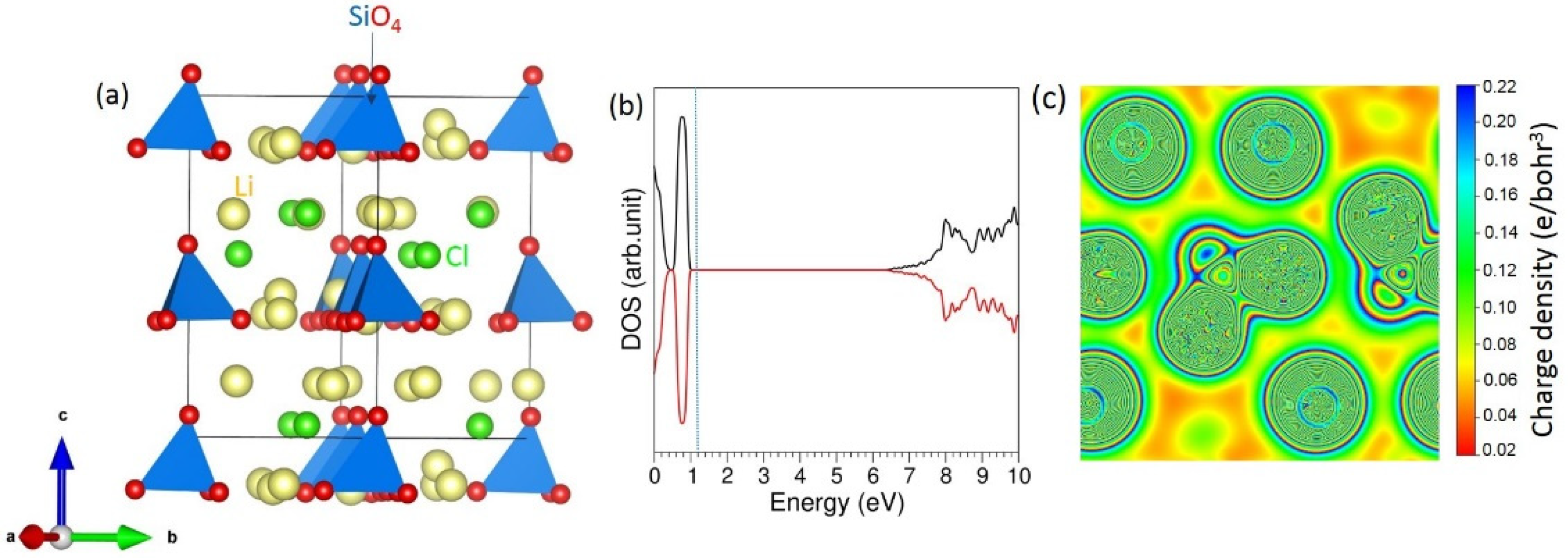
3.1. Bulk Structure of Li6SiO4Cl2

A recent combined experimental and theoretical study showed that although Li6SiO4Cl2 can exist in different phases, the most energetically stable phase is orthorhombic (space group Pna21) [20]. Its lattice constants are a = 10.5204 Å, b = 6.0756 Å, c = 9.9530 Å and α = β = γ = 90.0° [20]. In this structure, Li, Cl and Si form tetrahedral (LiO2Cl2), octahedral (ClLi6) and tetrahedral (SiO4) environments, respectively (see Figure 1). The current simulation study considered the most stable phase reported in the previous study [20], although the formation of other configurations of Li6SiO4Cl2 beyond the orthorhombic phase could be examined. Full geometry optimisation of this structure was carried out to compare calculated and experimentally observed structures. Table 1 shows the calculated and experimental lattice parameters and volume. An excellent agreement was observed (see Table 1), showing the efficacy of the pseudo-potentials and basis sets employed in this study. The percentage error calculated for each parameter was less than 1. The density of state (DOS) plot of bulk Li6SiO4Cl2 is shown in Figure 1b. It is an insulator with a band gap of 6.00 eV, showing the desirability of this material as an electrolyte material in Li-ion batteries. The electronic structure of this material was absent in the literature to compare the band gap value calculated in this study.
A Bader charge analysis was carried out to calculate the charges on the atoms in the bulk. The results tabulated in Table 2 clearly show that the crystal structure was ionic, with all ions consisting of full charges (Li+, Si4+, O2− and Cl).

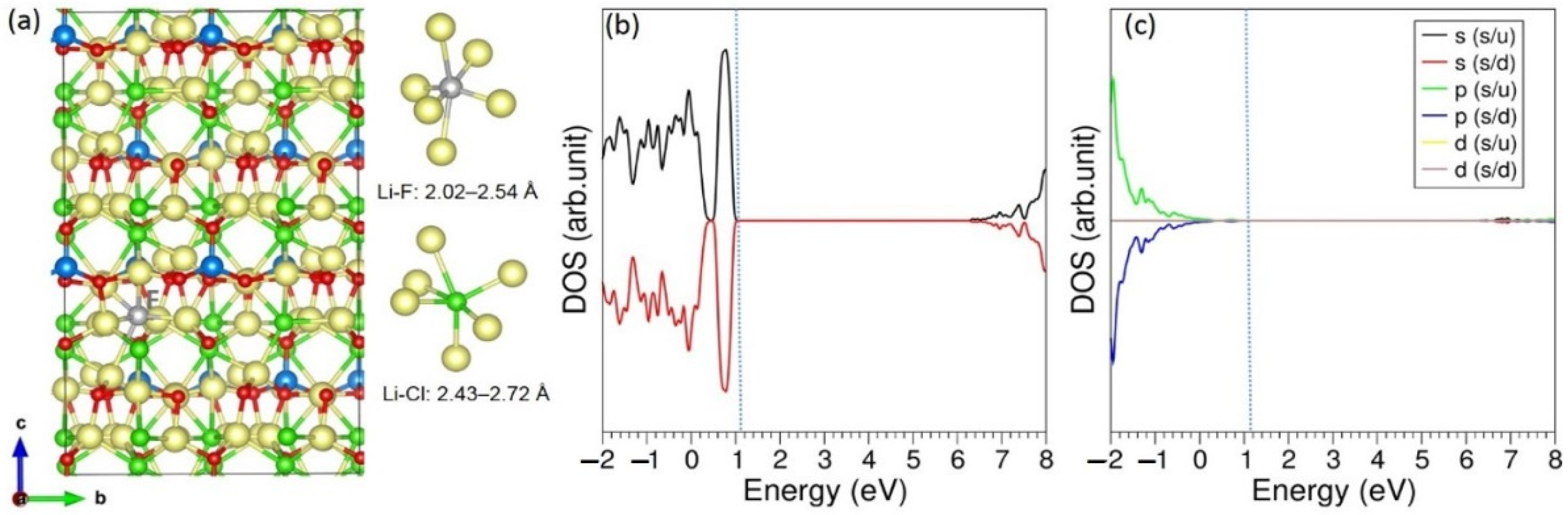
3.2. Intrinsic Defect Properties

Intrinsic defect processes are important as they influence the properties of materials. Here, the formation of Frenkel, Schottky and anti-site defect processes are examined. These defect processes require point defects together with their energies, as explained in the following equations consisting of Kröger–Vink notations [29]. While the Schottky defect produces many vacancies, in Frenkel defects, ions occupy interstitial positions. Both Schottky and Frenkel defect concentrations are temperature-dependent, and are generally expected to increase with increasing temperature [30]. Ionic conductivity of a material is controlled by Frenkel defects. In an experimental study, the mechanism for the high conductivity of Ag+ ions in all phases of AgI was explained using Frenkel defects [31]. The electronic conductivity enhancement was linked to the formation of Schottky defects in LaFeO3.
First, point defect energies were computed and associated to calculate Frenkel, Schottky and anti-site defect formation energies. The calculation formula for each defect process was reported in our previous simulation study [32] and is provided in the electronic supplmentary information (ESI). Ths total energies of point defects are also provided in the ESI (see Table S1).
Li   Frenkel :   Li Li X     V Li +   Li i
Si   Frenkel :   Si Si X     V Si +   Si i
Cl   Frenkel :   Cl Cl X     V Cl +   Cl i
O   Frenkel :   O O X     V O +   O i
Schottky : 6   Li Li   X + Si Si X   + 4   O O X + 2   Cl Cl X   6   V Li + V Si + 4   V O + 2   V Cl +   Li 6 SiO 4 Cl 2
Li 2 O   Schottky :   2   Li Li X +   O O X   2   V Li + V O + Li 2 O
LiCl   Schottky :   Li Li X +   Cl Cl X     V Li + V Cl + LiCl
SiO 2   Schottky :   Si Si X + 2   O O X     V Si + 2   V O + SiO 2
O / Cl   anti site   ( isolated ) :   O O X +   Cl Cl X   O Cl + Cl O
O / Cl   anti site   ( cluster ) :   O O X +   Cl Cl X   { O Cl : Cl O } X  
Defect formation energies calculated for all defects are listed in Table 3. The O–Cl anti-site defect cluster was the lowest energy defect process, inferring a small amount of anion mixing was possible in this material (0.07 eV/defect). The diffusion property of this material could be affected by this defect. Individual defects ( O Cl and   Cl O ) were considered separately in the isolated form of the anti-site defect. These two defects were simulated simultaneously in the cluster form. The formation of an anti-site defect cluster is exothermic (−3.64 eV), meaning that once the isolated defects are formed, there is a tendency to form cluster. Anti-site defect has been noticed in the experimental and theoretical characterization of many oxide materials [33,34,35,36]. We did not consider the Li-Si cation anti-site defect because the formation energy of this defect is expected to be highly positive according to our previous simulation study [37]. This is due to the large charge mismatch between Li+ and Si4+ ions. A cation anti-site defect containing Li can influence the Li diffusion properties. In an experimental study, it was shown that Li-ion migration pathways were affected by the anti-site defect consisting of Li and Fe in LiFePO4 [38]. Kempaiah et al. [39] observed the presence of Li atoms on the Ni site and vice versa in LiNiPO4 and discussed the electrochemical performance in the existence of an anti-site defect. The presence of an Li-Fe anti-site defect in the as-prepared Li2FeSiO4 was reported by Milović et al. [40] in their experimental and theoretical characterisation. This anti-site defect influenced the geometrical and electronic properties of Li2FeSiO4. The same anti-site defect was observed in Li2FeSiO4 only when this material was under cycling [41]. This clearly indicates that this defect is dependent on different synthetic conditions. Both Li-ion migration pathways and activation energies calculated for the cycled structure were different from those calculated for the as-prepared structure [41].
The next most favorable defect was the LiCl Schottky (2.88 eV/defect). This indicated that loss of LiCl is practicable at high temperatures only. The Li Frenkel defect energy was 2.94 eV/defect, meaning that the concentration of this defect was not very high. In previous simulation studies, the Li Frenkel was found to be the most dominant defect process [42,43]. The Cl Frenkel was more favorable than the O Frenkel. This indicated the concentration of Cl vacancies would be higher than that of O vacancies in this material. Other Frenkel and Schottky defect energies are highly endothermic, suggesting that they will not present at room temperature. In particular, the formation of Si Frenkel was hugely positive (10.39 eV/defect).

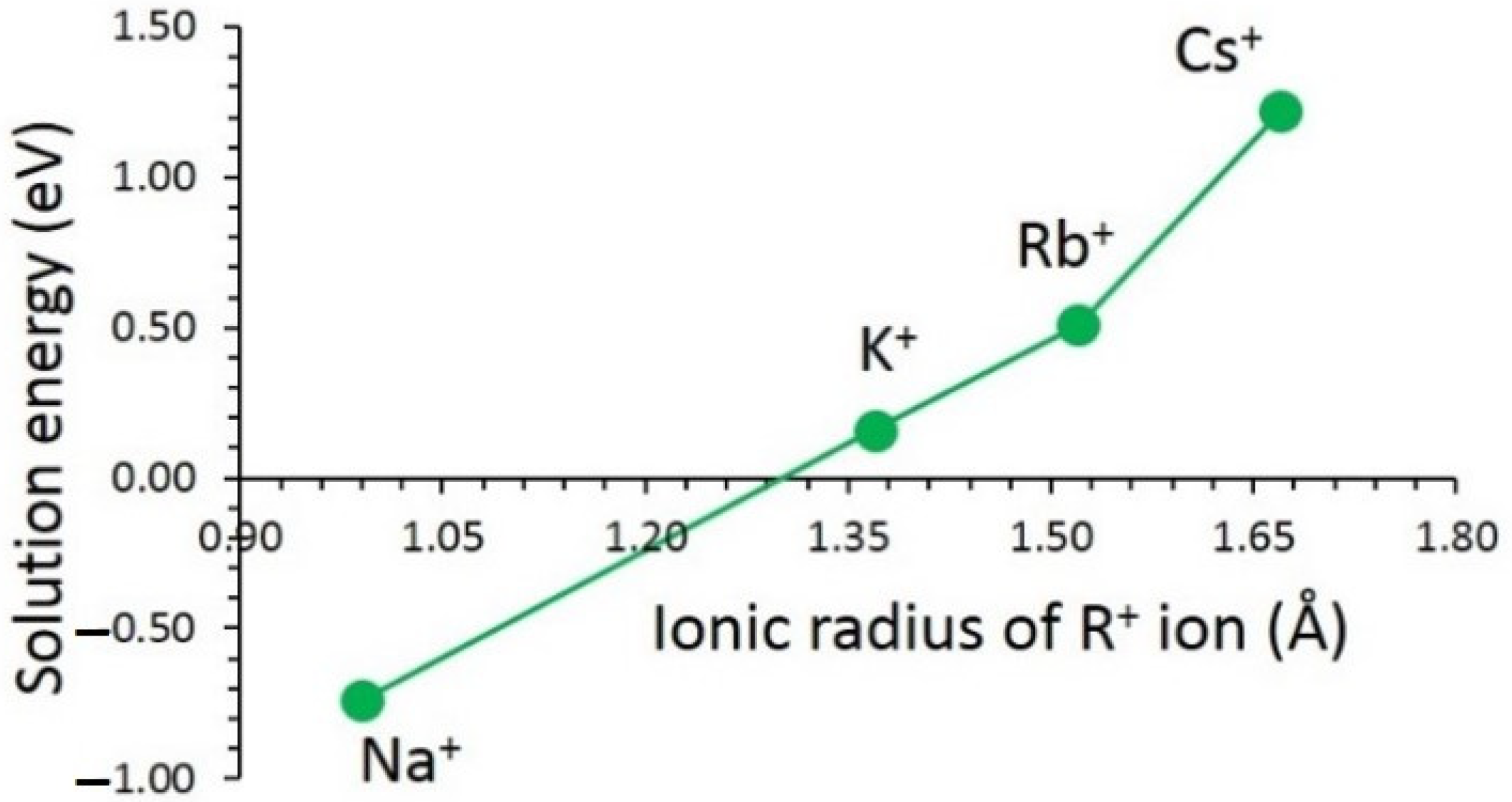
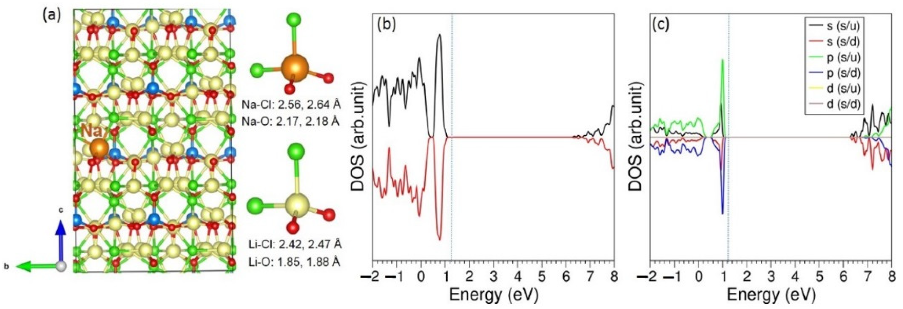
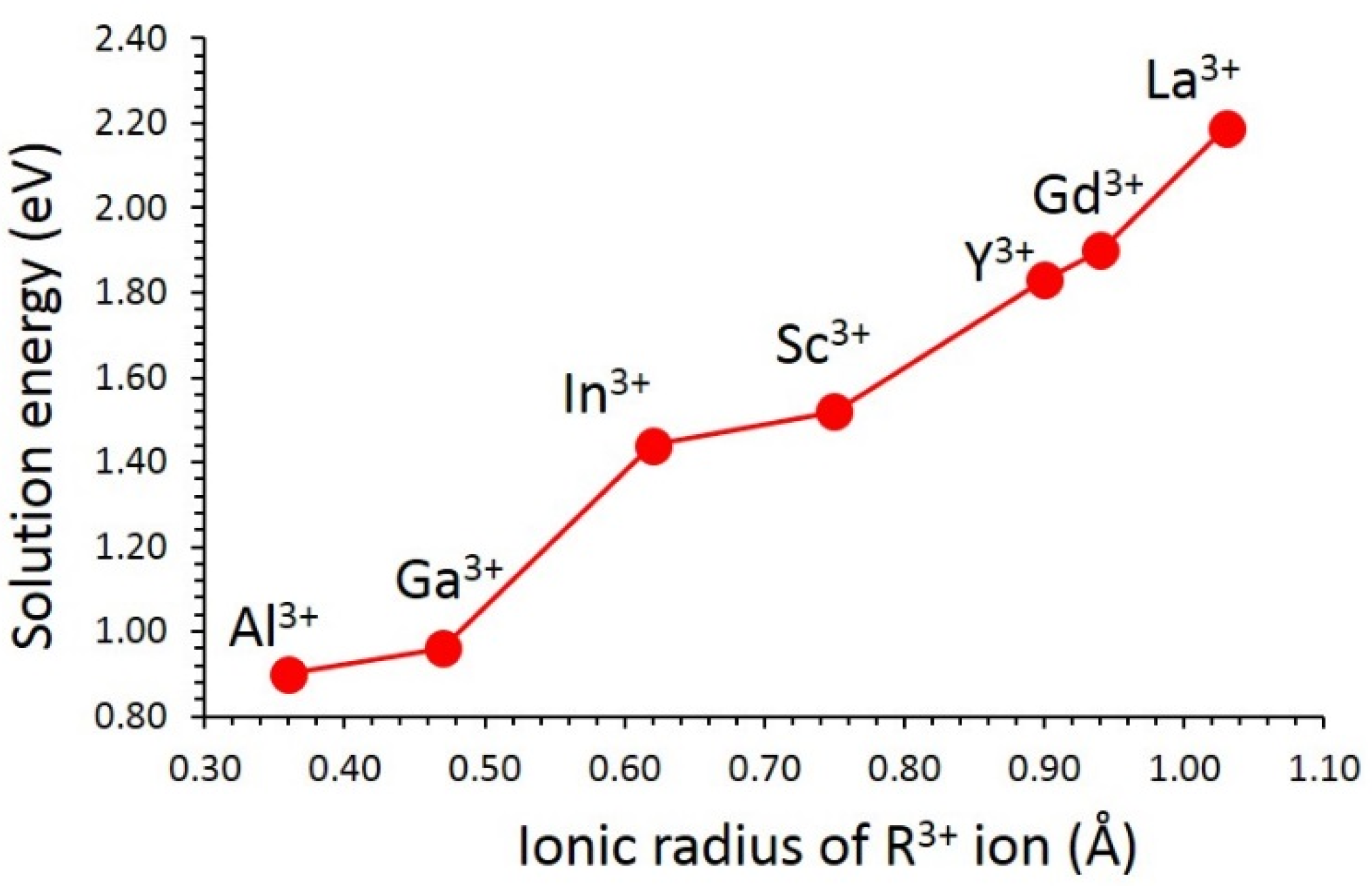
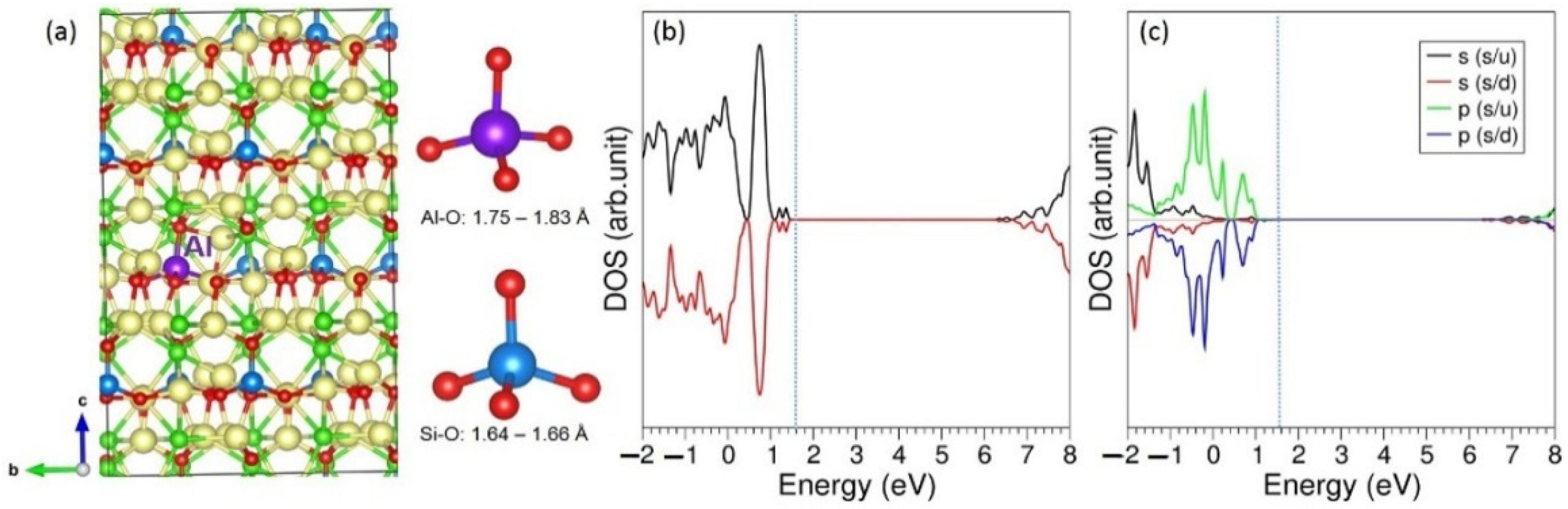
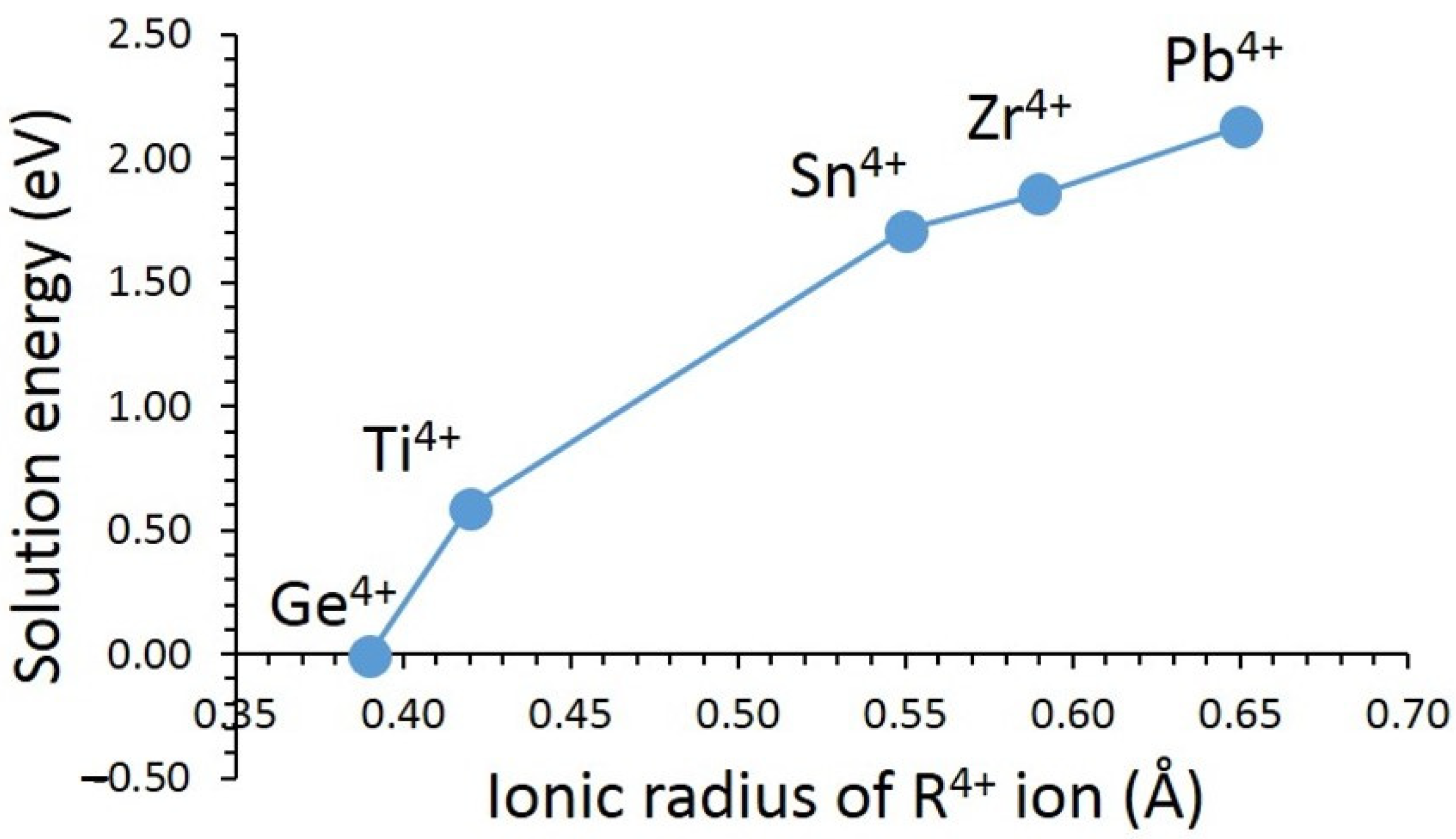
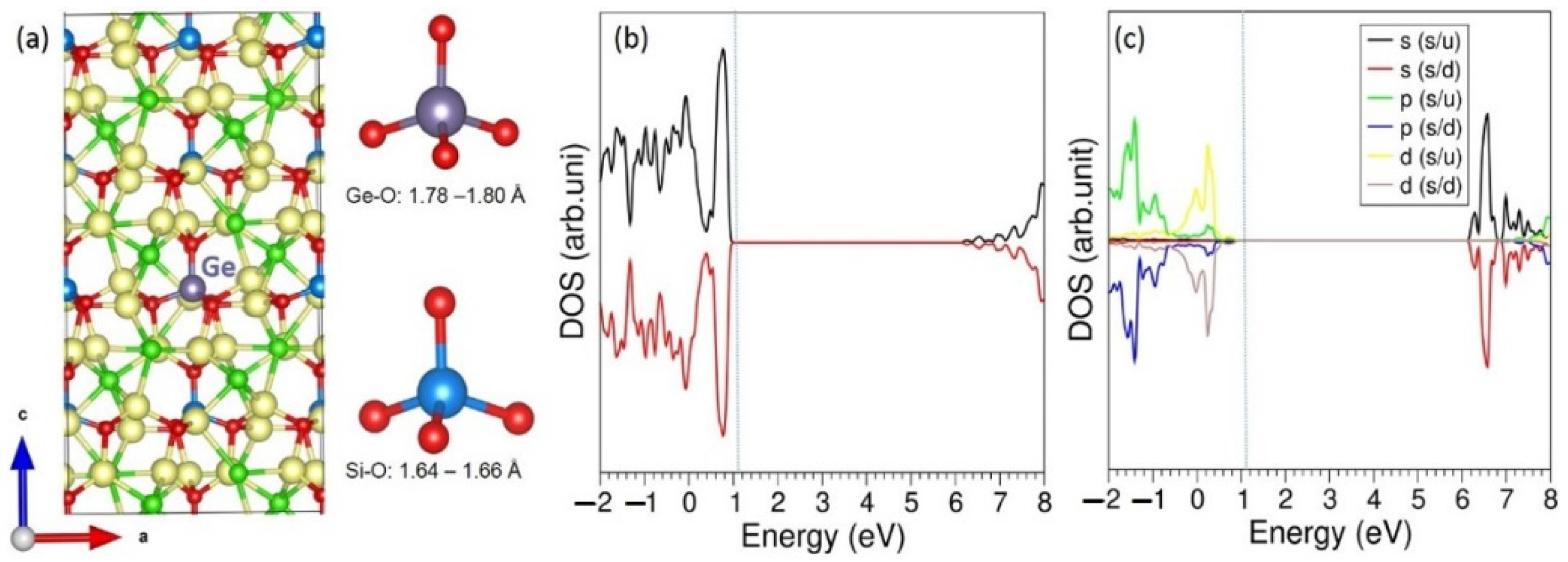
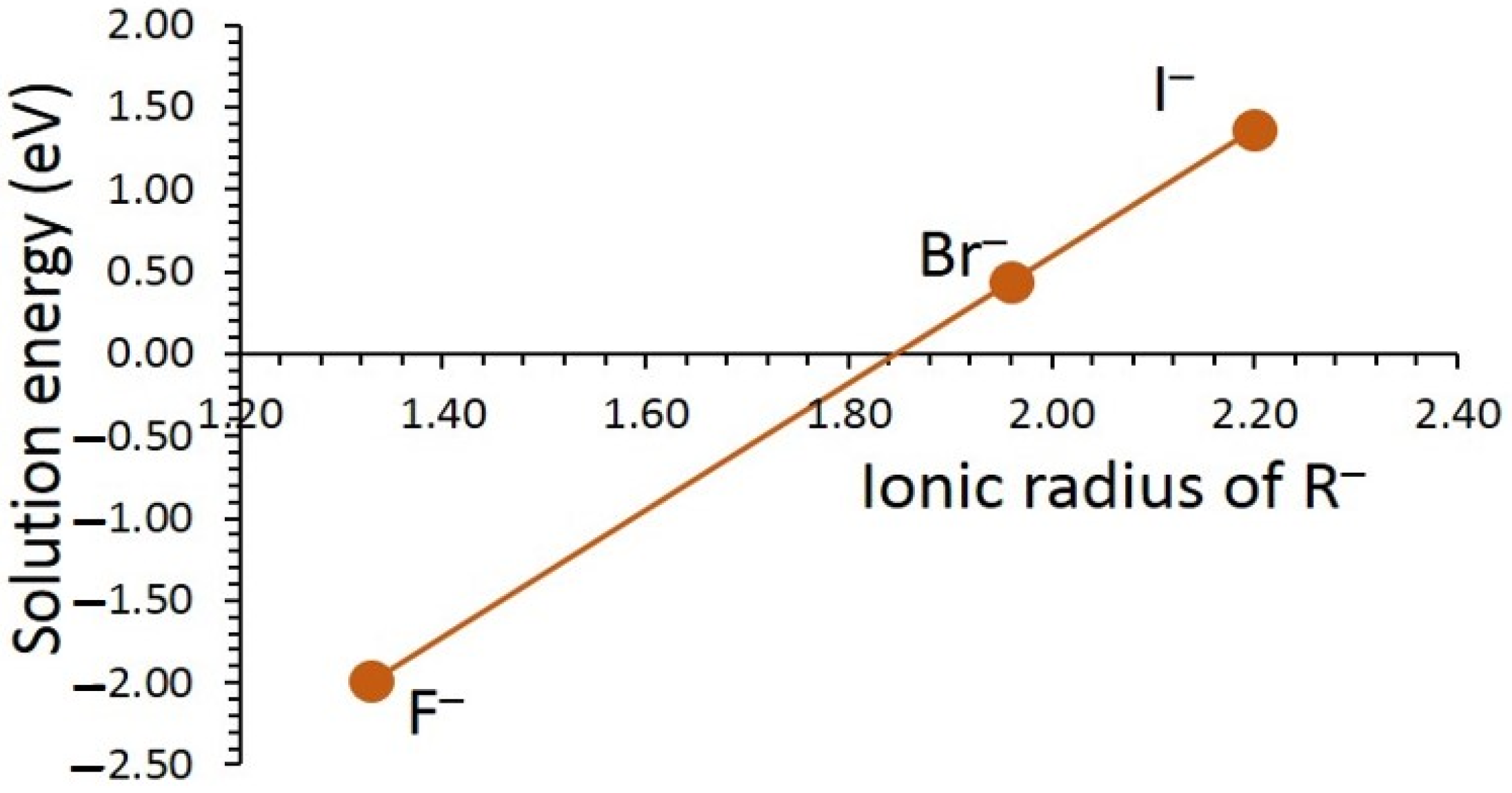
3.3. Solution of Dopants

A variety of metal oxides were examined to improve their properties via doping [44,45]. Yttria-doped zirconia is a promising ceramic electrolyte material with higher oxygen ion conductivity than pure zirconia [46]. The enhancement in the ionic conductivity is related to the presence of point defects controlling the transport properties at grainboundaries [46]. In a combined experimental and thoeretical study [47], it was demonstrated that substituting Ru on the Fe site in LiFePO4 improved the Li-ion movement via reduction of the Li-Li separation in the lattice and electrical conductivity. Substitutional doping on the Li, Si and Cl sites can tune the properties of Li6SiO4Cl2. Here, we considered both isovalent and aliovalent dopants. Necessary charge compensating defects (vacancies and interstitials) were introduced together with approriate lattice energies. The favourable dopants can be of interest for future experimental studies.
First, alkali metal dopants (R = Na, K, Rb and Cs) were doped on the Li site. Solution energies were calculated by using the following equation.
R 2 O   +   2   Li Li X   2 R Li X +   Li 2 O  
Figure 2 shows the solution energies for the monovalent dopants. The most promising dopant was found to be the Na+. Exothermic solution energy (−0.74 eV) was calculated for this dopant. This was partly due to the smaller ionic radius of Na+ than that of the other dopant ions (see Figure 2). The next most favorable dopant was the K+. However, doping of this cation was endothermic. Once the ionic radius increased, solution energy also increased. The most inappropriate dopant was the Cs+, and this cation could not be doped at room temperature. The possible doped structural formula is Li6−xNaxSiO4Cl2 (x = 0.0–1.0). The doping of Na on the Li site was considered in an experimental study by Xue et al. [48] to reduce the concentration of Li in a mixed oxide Li1.2Mn0.54Ni0.13Co0.13O2 as this overlithated material exhibited poor stability during cycling, and attenuation of voltage, although high capacity was achieved. There was an enhancement in the electrochemical property, cycling performance and reduction in voltage attenuation upon Na doping. As Li6SiO4Cl2 is also an overlithiated material, doping of Na can be an effective method to improve the electrochemical properties of this material. In another experimental study by Shen et al. [49], the doping of Na in a “layered” LiNi0.6Co0.05Mn0.35O2 inhibited phase transition and cation mixing (Li/Ni), and improved the performance of Li storage.
The DFT-optimized structure of Na-doped Li6SiO4Cl2 is shown in Figure 3a. There was an elongation in the bond distances (Na–O and Na–Cl) upon doping. This was due to the smaller ionic radius of Li+ than Na+. The electronic structure had a very small alteration upon doping, and the doped configuration was still an insulator. The p-states of Na lay closer to the Fermi level at 1.05 eV.
Next, trivalent dopants were considered on the Si site, as they are most interesting for practical application. This doping process introduced additional Li interstitials as charge compensating defects required for the enhancement in capacity, as defined by Equation (12).
R 2 O 3 + 2   Si Si X + Li 2 O   2   R Si + 2   Li i + 2   SiO 2
The results derived from these calculations are summarized in Figure 4. The most promising dopant was the Al3+ (see Figure 4). This was due to the ionic radius of Al3+ (0.39 Å) matching closely with the ionic radius of Si4+ (0.26 Å). The solution energy calculated for the Ga3+ was higher—only by 0.06 eV—than that calculated for the Al3+, suggesting that this dopant is also worth trying experimentally. A gradual increase in the solution energy with increasing ionic radius was observed. The doping of La3+ was unfavorable as its solution energy was highly positive (2.19 eV). Previous experimental studies show that Al doping in various Li-containing electrode materials enhances the capacity and electrochemical performance [50,51,52]. In a previous simulation study, it was shown that Al doping on the Si site is the lowest energy process in Li2MnSiO4 [53]. It was later confirmed in an experimental study by Duncan et al. [54].
The DFT-optimized structure of Al-doped Li6SiO4Cl2 is shown in Figure 5a. The doped Al formed longer Al–O bonds with nearest neighbor oxygen atoms than Si–O bonds. This was associated with the fact that the ionic radius of Al3+ is larger than that of Si4+. Furthermore, AlO4 tetrahedral units were slightly distorted upon doping. The DOS plots show that there was a slight increase in the Fermi energy. However, insulating character of this material was unchanged.
Different tetravalent dopants were next substituted on the Si site. The following reaction equation explains the doping process.
RO 2 +   Si Si   X R Si   X + SiO 2
Solution energies calculated for the tetravalent dopants are provided in Figure 6. The energy of solution calculated for the dopant Ge4+ was −0.01 eV (see Figure 6). This dopant was predicted to be thermodynamically favorable. The suitability of this dopant was due to its ionic radius being closer to that of Si4+. The second promising dopant was Ti4+ with a solution energy of 0.59 eV. The other three dopants (Sn4+, Zr4+ and Pb4+) exhibited higher solution energies (>1.70 eV) owing to their ionic radii being larger than the ionic radius of Si4+. The doping of Pb4+ was highly unfavorable with a solution energy of 2.15 eV. In previous theoretical studies, the Ge4+ ion was identified as a candidate dopant ion on the Si site in silicate materials [37,55]
The longer Ge–O bond distances were the result of the larger ionic radius of Ge4+ (see Figure 7a) although the tetrahedral units were not much distorted. Both Femi energy level and the band gap value were not altered significantly upon Ge doping (see Figure 7b,c).
Finally, the Cl site was considered for doping other halogen atoms according to the following reaction equation.
1 2 R 2 +   Cl Cl   X R Cl   X + 1 2 Cl 2
Calculated solution energies vs. ionic radii of halogen ions are shown in Figure 8. The smaller ionic radius of F compared with Cl reflected in the exothermic solution energy (−1.99 eV) (see Figure 8). Solution energies were positive for both Br (0.44 eV) and I (1.37 eV) as their ionic radii are larger than that of Cl. High positive solution energy of I indicated that heat energy was required for this dopant to overcome the activation energy. Substitution of F on the Cl or Br site in the antiperovskite Li2OHR (R = Cl or Br) solid electrolyte material was shown to exhibit excellent electrochemical stability with high voltage [56].
The optimized F-doped structure is shown in Figure 9a. The Li–F bond distances were shorter than the Li–Cl bond distances, indicating the strong ionic bonding between Li+ and F ions. The DOS plots show that the doped configuration was an insulator and the band gap was unaltered upon doping (see Figure 9b,c).

3.4. Formation of Li6SiO4Cl2

Different chemical reaction routes were established to calculate the formation energy of one mole of Li6SiO4Cl2. Table 4 reports the type of reactions and their reaction energies. In all cases, atom economy [57] ( atom   economy = mass   of   desired   product total   mass   of   reactants × 100 ) was 100%. In the first reaction, Li4SiO4 and LiCl were considered as reactants and the reaction was exothermic with a reaction energy of −0.12 eV. The second reaction was even more exothermic, and in this reaction Li2O, Li2SiO3 and LiCl were used as reactants. In the reaction 3, one mole of SiO2 and one mole of Li2O were used as reactants instead of one mole of Li2SiO3, and the reaction energy was more negative than that calculated in reaction 2. The fourth reaction was slightly more favourable than the third reaction. In this reaction process, one mole of Li3OCl was used instead of one mole of LiCl and one mole of Li2O. An additional mole of Li3OCl was introduced and both Li2O and LiCl were removed in the fifth reaction. This reaction was more feasible, showing that the Li3OCl should be a promising ingredient in the preparation of Li6SiO4Cl2. This could partly be due to the exothermic reaction of Li2O + LiCl → Li3OCl (−0.22 eV, calculated in this study). Finally, constituent elements were used as reactants in reaction six, to prepare Li6SiO4Cl2. The reaction was hugely negative, meaning that this route is theoretically feasible. Furthermore, this reaction pathway was over an order of magnitude more exothermic than the others listed in the table.

3.5. Li-Incorporation

Thermodynamical stability of Li6SiO4Cl2 upon extra Li (up to three) was examined by relaxing the ion positions and lattice constants of Li-incorporated structures. The possible configurations considered in this study are shown in the ESI (Figures S1–S3). Incorporation energies, Bader charges on the incorporate Li atoms, volume changes and electronic structures of resultant configurations were calculated. The optimized configurations are shown in Figure 10. The calculated incorporation energies were positive, inferring the instability of the incorporated Li atoms (see Table 5). The energies to incorporate Li atoms calculated using bulk Li as chemical potential were highly positive compared with those calculated using Li atom as chemical potential. This was due to the additional energy needed to dissociate bulk Li to form Li atoms. Bader charge analysis showed the loss of electrons from Li atoms forming single positively charged Li+ ions. A gradual increase in the volume was observed for each Li incorporation. Such increment in the volume facilitated the incorporation. The Fermi energy level shifted significantly for each incorporation and the resultant configurations became metallic with the loss of electrons from the incorporated Li atoms in the lattice.

4. Conclusions

Ab initio simulations based on the density functional theory were performed to examine the defect properties, doping process, different synthetic routes, and Li-incorporation. We found that the most thermodynamically promising defect process was the O–Cl anti-site defect cluster, indicating that there was a small amount of anion mixing present in this material. The LiCl Schottky was the second most favorable defect. This defect can lead to the loss of LiCl. The Li Frenkel was also a competent defect and its defect energy was 0.06 eV lower than the LiCl Schottky. Na, Ge and F were identified as the most promising isovalent dopants on the Li, Si and Cl sites, respectively. Exerting additional Li-ions was possible by the doping of Al on the Si site. The formation reaction of Li6SiO4Cl2 was examined and the reaction consisting of constituent elements as reactants was highly exothermic. Incorporation of extra Li in this material was not feasible with respect to both Li atom and Li bulk. Furthermore, incorporated Li atoms became Li+ ions losing their outer electrons, and there was a gradual expansion in the volume. Exoergic solution energies calculated for Na+, Ge4+ and F necessitate experimental verification.

Supplementary Materials

The following supporting information can be downloaded at: https://www.mdpi.com/article/10.3390/batteries8100137/s1, Table S1: Total energies of point defects calculated in the 1 × 2 × 2 supercell; Figure S1: Different configurations of a single Li incorporated into Li6SiO4Cl2; Figure S2: Different configurations of two Li atoms incorporated into Li6SiO4Cl2; Figure S3: Different configurations of three Li atoms incorporated into Li6SiO4Cl2.

Funding

This research received no external funding.

Informed Consent Statement

Not applicable.

Data Availability Statement

Not applicable.

Acknowledgments

The high-performance computing center at Imperial College London is acknowledged for providing computational facilities to run VASP code.

Conflicts of Interest

The author declares no conflict of interest.

References

  1. Weiss, M.; Ruess, R.; Kasnatscheew, J.; Levartovsky, Y.; Levy, N.R.; Minnmann, P.; Stolz, L.; Waldmann, T.; Wohlfahrt-Mehrens, M.; Aurbach, D.; et al. Fast Charging of Lithium-Ion Batteries: A Review of Materials Aspects. Adv. Energy Mater. 2021, 11, 2101126. [Google Scholar] [CrossRef]
  2. Kim, T.; Song, W.; Son, D.-Y.; Ono, L.K.; Qi, Y. Lithium-ion batteries: Outlook on present, future, and hybridized technologies. J. Mater. Chem. A 2019, 7, 2942–2964. [Google Scholar] [CrossRef]
  3. Li, M.; Lu, J.; Chen, Z.; Amine, K. 30 Years of Lithium-Ion Batteries. Adv. Mater. 2018, 30, 1800561. [Google Scholar] [CrossRef] [PubMed]
  4. Cherkashinin, G.; Hausbrand, R.; Jaegermann, W. Performance of Li-Ion Batteries: Contribution of Electronic Factors to the Battery Voltage. J. Electrochem. Soc. 2019, 166, A5308–A5312. [Google Scholar] [CrossRef]
  5. Blomgren, G.E. The Development and Future of Lithium Ion Batteries. J. Electrochem. Soc. 2016, 164, A5019–A5025. [Google Scholar] [CrossRef]
  6. Agostini, M.; Brutti, S.; Navarra, M.A.; Panero, S.; Reale, P.; Matic, A.; Scrosati, B. A high-power and fast charging Li-ion battery with outstanding cycle-life. Sci. Rep. 2017, 7, 1104. [Google Scholar] [CrossRef]
  7. Deng, D. Li-ion batteries: Basics, progress, and challenges. Energy Sci. Eng. 2015, 3, 385–418. [Google Scholar] [CrossRef]
  8. Tang, W.; Zhu, Y.; Hou, Y.; Liu, L.; Wu, Y.; Loh, K.P.; Zhang, H.; Zhu, K. Aqueous rechargeable lithium batteries as an energy storage system of superfast charging. Energy Environ. Sci. 2013, 6, 2093–2104. [Google Scholar] [CrossRef]
  9. Xu, K. Electrolytes and Interphases in Li-Ion Batteries and Beyond. Chem. Rev. 2014, 114, 11503–11618. [Google Scholar] [CrossRef]
  10. Han, L.; Lehmann, M.L.; Zhu, J.; Liu, T.; Zhou, Z.; Tang, X.; Heish, C.-T.; Sokolov, A.P.; Cao, P.; Chen, X.C.; et al. Recent Developments and Challenges in Hybrid Solid Electrolytes for Lithium-Ion Batteries. Front. Energy Res. 2020, 8, 202. [Google Scholar] [CrossRef]
  11. Sauter, C.; Zahn, R.; Wood, V. Understanding Electrolyte Infilling of Lithium Ion Batteries. J. Electrochem. Soc. 2020, 167, 100546. [Google Scholar] [CrossRef]
  12. Kwon, W.J.; Kim, H.; Jung, K.-N.; Cho, W.; Kim, S.H.; Lee, J.-W.; Park, M.-S. Enhanced Li+ conduction in perovskite Li3xLa2/3−x□1/3−2xTiO3 solid-electrolytes via microstructural engineering. J. Mater. Chem. A 2017, 5, 6257–6262. [Google Scholar] [CrossRef]
  13. Heenen, H.H.; Voss, J.; Scheurer, C.; Reuter, K.; Luntz, A.C. Multi-ion Conduction in Li3OCl Glass Electrolytes. J. Phys. Chem. Lett. 2019, 10, 2264–2269. [Google Scholar] [CrossRef] [PubMed]
  14. El-Shinawi, H.; Greaves, C.; Janek, J. Sol–gel synthesis and room-temperature properties of α-LiZr2(PO4)3. RSC Adv. 2015, 5. [Google Scholar] [CrossRef]
  15. Shao, C.; Liu, H.; Yu, Z.; Zheng, Z.; Sun, N.; Diao, C. Structure and ionic conductivity of cubic Li7La3Zr2O12 solid electrolyte prepared by chemical co-precipitation method. Solid State Ion. 2016, 287, 13–16. [Google Scholar] [CrossRef]
  16. Yu, G.; Wang, Y.; Li, K.; Chen, D.; Qin, L.; Xu, H.; Chen, J.; Zhang, W.; Zhang, P.; Sun, Z. Solution-processable Li10GeP2S12 solid electrolyte for a composite electrode in all-solid-state lithium batteries. Sustain. Energy Fuels 2021, 5, 1211–1221. [Google Scholar] [CrossRef]
  17. López-Aranguren, P.; Reynaud, M.; Głuchowski, P.; Bustinza, A.; Galceran, M.; del Amo, J.M.L.; Armand, M.; Casas-Cabanas, M. Crystalline LiPON as a Bulk-Type Solid Electrolyte. ACS Energy Lett. 2021, 6, 445–450. [Google Scholar] [CrossRef]
  18. Kuganathan, N.; Chroneos, A. Defects, dopants and lithium incorporation in LiPON electrolyte. Comput. Mater. Sci. 2021, 202, 111000. [Google Scholar] [CrossRef]
  19. Shin, D.O.; Oh, K.; Kim, K.M.; Park, K.-Y.; Lee, B.; Lee, Y.-G.; Kang, K. Synergistic multi-doping effects on the Li7La3Zr2O12 solid electrolyte for fast lithium ion conduction. Sci. Rep. 2015, 5, 18053. [Google Scholar] [CrossRef]
  20. Morscher, A.; Dyer, M.S.; Duff, B.B.; Han, G.; Gamon, J.; Daniels, L.M.; Dang, Y.; Surta, W.; Robertson, C.M.; Blanc, F.; et al. Li6SiO4Cl2: A Hexagonal Argyrodite Based on Antiperovskite Layer Stacking. Chem. Mater. 2021, 33, 2206–2217. [Google Scholar]
  21. Spotte-Smith, E.W.C.; Blau, S.M.; Xie, X.; Patel, H.D.; Wen, M.; Wood, B.; Dwaraknath, S.; Persson, K.A. Quantum chemical calculations of lithium-ion battery electrolyte and interphase species. Sci. Data 2021, 8, 203. [Google Scholar] [CrossRef] [PubMed]
  22. Urban, A.; Seo, D.-H.; Ceder, G. Computational understanding of Li-ion batteries. npj Comput. Mater. 2016, 2, 16002. [Google Scholar] [CrossRef]
  23. Kresse, G.; Furthmüller, J. Efficient iterative schemes for ab initio total-energy calculations using a plane-wave basis set. Phys. Rev. B 1996, 54, 11169–11186. [Google Scholar] [CrossRef] [PubMed]
  24. Blöchl, P.E. Projector augmented-wave method. Phys. Rev. B Condens. Matter Mater. Phys. 1994, 50, 17953–17979. [Google Scholar] [CrossRef] [PubMed]
  25. Monkhorst, H.J.; Pack, J.D. Special points for Brillouin-zone integrations. Phys. Rev. B 1976, 13, 5188. [Google Scholar] [CrossRef]
  26. Perdew, J.P.; Burke, K.; Ernzerhof, M. Generalized gradient approximation made simple. Phys. Rev. Lett. 1996, 77, 3865. [Google Scholar] [CrossRef]
  27. Press, W.H.; Teukolsky, S.A.; Vetterling, W.T.; Flannery, B.P. Numerical Recipes in C, 2nd ed.; The Art of Scientific Computing; Cambridge University Press: Cambridge, UK, 1992. [Google Scholar]
  28. Bader, R.F.W. The zero-flux surface and the topological and quantum definitions of an atom in a molecule. Theor. Chim. Acta 2001, 105, 276–283. [Google Scholar] [CrossRef]
  29. Kröger, F.A.; Vink, H.J. Relations between the Concentrations of Imperfections in Crystalline Solids. In Solid State Physics; Seitz, F., Turnbull, D., Eds.; Academic Press: Cambridge, MA, USA, 1956; Volume 3, pp. 307–435. [Google Scholar]
  30. Vineyard, G.H.; Dienes, G.J. The Theory of Defect Concentration in Crystals. Phys. Rev. 1954, 93, 265–268. [Google Scholar] [CrossRef]
  31. Lee, J.S.; Adams, S.; Maier, J. Defect chemistry and transport characteristics of β-AgI. J. Phys. Chem. Solids 2000, 61, 1607–1622. [Google Scholar] [CrossRef]
  32. Kuganathan, N.; Chroneos, A. Formation, doping, and lithium incorporation in LiFePO4. AIP Adv. 2022, 12, 045225. [Google Scholar] [CrossRef]
  33. Kim, Y. Theoretical investigation of the cation antisite defect in layer-structured cathode materials for Li-ion batteries. Phys. Chem. Chem. Phys. 2019, 21, 24139–24146. [Google Scholar] [CrossRef] [PubMed]
  34. Werner, J.; Neef, C.; Koo, C.; Zvyagin, S.; Ponomaryov, A.; Klingeler, R. Antisite disorder in the battery material LiFePO4. Phys. Rev. Mater. 2020, 4, 115403. [Google Scholar] [CrossRef]
  35. Raj, H.; Rani, S.; Sil, A. Antisite Defects in Sol-Gel-Synthesized LiFePO4at Higher Temperature: Effect on Lithium-Ion Diffusion. ChemElectroChem 2018, 5, 3525–3532. [Google Scholar] [CrossRef]
  36. Tang, Z.; Wang, S.; Liao, J.; Wang, S.; He, X.; Pan, B.; He, H.; Chen, C. Facilitating Lithium-Ion Diffusion in Layered Cathode Materials by Introducing Li+/Ni2+ Antisite Defects for High-Rate Li-Ion Batteries. Research 2019, 2019, 2198906. [Google Scholar] [CrossRef]
  37. Kuganathan, N.; Tsoukalas, L.; Chroneos, A. Defects, dopants and Li-ion diffusion in Li2SiO3. Solid State Ion. 2019, 335, 61–66. [Google Scholar] [CrossRef]
  38. Liu, H.; Choe, M.-J.; Enrique, R.A.; Orvañanos, B.; Zhou, L.; Liu, T.; Thornton, K.; Grey, C.P. Effects of Antisite Defects on Li Diffusion in LiFePO4 Revealed by Li Isotope Exchange. J. Phys. Chem. C 2017, 121, 12025–12036. [Google Scholar] [CrossRef]
  39. Devaraju, M.K.; Truong, Q.D.; Hyodo, H.; Sasaki, Y.; Honma, I. Synthesis, characterization and observation of antisite defects in LiNiPO4 nanomaterials. Sci. Rep. 2015, 5, 11041. [Google Scholar] [CrossRef]
  40. Milović, M.D.; Anicijevic, D.V.; Jugovic, D.; Anićijević, V.J.; Veselinović, L.; Mitrić, M.; Uskoković, D. On the presence of antisite defect in monoclinic Li2FeSiO4—A combined X-Ray diffraction and DFT study. Solid State Sci. 2018, 87, 81–86. [Google Scholar] [CrossRef]
  41. Armstrong, A.R.; Kuganathan, N.; Islam, M.S.; Bruce, P.G. ChemInform Abstract: Structure and Lithium Transport Pathways in Li2FeSiO4 Cathodes for Lithium Batteries. ChemInform 2011, 42, 13031–13035. [Google Scholar] [CrossRef]
  42. Kuganathan, N.; Kordatos, A.; Chroneos, A. Defect Chemistry and Li-ion Diffusion in Li2RuO3. Sci. Rep. 2019, 9, 550. [Google Scholar] [CrossRef]
  43. Kuganathan, N.; Kordatos, A.; Fitzpatrick, M.; Vovk, R.; Chroneos, A. Defect process and lithium diffusion in Li2TiO3. Solid State Ion. 2018, 327, 93–98. [Google Scholar] [CrossRef]
  44. Yang, X.; Zhang, H.; Xu, W.; Yu, B.; Liu, Y.; Wu, Z. A doping element improving the properties of catalysis: In situ Raman spectroscopy insights into Mn-doped NiMn layered double hydroxide for the urea oxidation reaction. Catal. Sci. Technol. 2022, 12, 4471–4485. [Google Scholar] [CrossRef]
  45. Wu, X.-W.; Kai, Z.; Sheng, H.; Fu, L.; Liu, Z.; Zhou, C.; Holze, R.; Wu, Y. Improving electrochemical properties by sodium doping for lithium-rich layered oxides. ACS Appl. Energy Mater. 2020, 3, 8953–8959. [Google Scholar] [CrossRef]
  46. Park, J.S.; Kim, Y.-B.; An, J.; Prinz, F.B. Oxygen diffusion across the grain boundary in bicrystal yttria stabilized zirconia. Solid State Commun. 2012, 152, 2169–2171. [Google Scholar] [CrossRef]
  47. Gao, Y.; Xiong, K.; Zhang, H.; Zhu, B. Effect of Ru Doping on the Properties of LiFePO4/C Cathode Materials for Lithium-Ion Batteries. ACS Omega 2021, 6, 14122–14129. [Google Scholar] [CrossRef]
  48. Xue, Z.; Qi, X.; Li, L.; Li, W.; Xu, L.; Xie, Y.; Lai, X.; Hu, G.; Peng, Z.; Cao, Y.; et al. Sodium Doping to Enhance Electrochemical Performance of Overlithiated Oxide Cathode Materials for Li-Ion Batteries via Li/Na Ion-Exchange Method. ACS Appl. Mater. Interfaces 2018, 10, 27141–27149. [Google Scholar] [CrossRef]
  49. Huang, Z.; Wang, Z.; Jing, Q.; Guo, H.; Li, X.; Yang, Z. Investigation on the effect of Na doping on structure and Li-ion kinetics of layered LiNi0.6Co0.2Mn0.2O2 cathode material. Electrochim. Acta 2016, 192, 120–126. [Google Scholar] [CrossRef]
  50. Gao, Y.; Yuan, W.; Dou, X. Improvement of the High-Performance Al-Doped LiNi1/3Co1/3Mn1/3O2 Cathode Material for New Electro-Optical Conversion Devices. Front. Phys. 2021, 9, 731851. [Google Scholar] [CrossRef]
  51. Du, H.; Zhang, X.; Chen, Z.; Wu, D.; Zhang, Z.; Li, J. Carbon coating and Al-doping to improve the electrochemistry of Li2CoSiO4 polymorphs as cathode materials for lithium-ion batteries. RSC Adv. 2018, 8, 22813–22822. [Google Scholar] [CrossRef]
  52. Zhao, W.; Zou, L.; Jia, H.; Zheng, J.; Wang, D.; Song, J.; Hong, C.; Liu, R.; Xu, W.; Yang, Y.; et al. Optimized Al Doping Improves Both Interphase Stability and Bulk Structural Integrity of Ni-Rich NMC Cathode Materials. ACS Appl. Energy Mater. 2020, 3, 3369–3377. [Google Scholar] [CrossRef]
  53. Kuganathan, N.; Islam, M.S. Li2MnSiO4 Lithium Battery Material: Atomic-Scale Study of Defects, Lithium Mobility, and Trivalent Dopants. Chem. Mater. 2009, 21, 5196–5202. [Google Scholar] [CrossRef]
  54. Duncan, H.; Aboud, D.; Maiocco, C.; Abu-Lebdeh, Y.; Davidson, I.J. Improvement of the Battery Performance of Li2MnSiO4 by Aliovalent (Al3+) Doping. ECS Meet. Abstr. 2010, MA2010-03, 483. [Google Scholar] [CrossRef]
  55. Kuganathan, N. Intrinsic Defects, Diffusion and Dopants in AVSi2O6 (A = Li and Na) Electrode Materials. Batteries 2022, 8, 20. [Google Scholar] [CrossRef]
  56. Li, Y.; Zhou, W.; Xin, S.; Li, S.; Zhu, J.; Lü, X.; Cui, Z.; Jia, Q.; Zhou, J.; Zhou, Y.; et al. Fluorine-Doped Antiperovskite Electrolyte for All-Solid-State Lithium-Ion Batteries. Angew. Chem. Int. Ed. 2016, 55, 9965–9968. [Google Scholar] [CrossRef] [PubMed]
  57. Song, Q.-W.; He, L.-N. Atom Economy. In Encyclopedia of Sustainability Science and Technology; Meyers, R.A., Ed.; Springer: New York, NY, USA, 2018; pp. 1–21. [Google Scholar]
Figure 1. (a) Crystal structure, (b) total DOS plot, and (c) charge density plot showing the bonding interaction between ions in Li6SiO4Cl2.
Batteries 08 00137 g001
Figure 2. Calculated solution energies of monovalent dopants on the Li site.
Batteries 08 00137 g002
Figure 3. (a) Optimized structure of Na-doped Li6SiO4Cl2, (b) its total DOS plot, and (c) atomic DOS plot of Na.
Batteries 08 00137 g003
Figure 4. Calculated solution energies of trivalent dopants on the Si site.
Batteries 08 00137 g004
Figure 5. (a) Optimized structure of Al-doped Li6SiO4Cl2, (b) its total DOS plot, and (c) atomic DOS plot of Al.
Batteries 08 00137 g005
Figure 6. Solution energies of tetravalent dopants on the Si site.
Batteries 08 00137 g006
Figure 7. (a) Optimized structure of Ge-doped Li6SiO4Cl2, (b) DOS plot, and (c) atomic DOS plot of Ge.
Batteries 08 00137 g007
Figure 8. Calculated solution energies of halogen dopants on the Cl site.
Batteries 08 00137 g008
Figure 9. (a) Relaxed structure of F-doped Li6SiO4Cl2, (b) DOS plot, and (c) atomic DOS plot of F.
Batteries 08 00137 g009
Figure 10. DFT-optimized structures of (a) a single Li, (b) two Li and (c) 3 Li incorporated in Li6SiO4Cl2. Total DOS plots (df), and atomic plots of Li (gi), are also shown.
Batteries 08 00137 g010
Table 1. Calculated and experimental parameters of Li6SiO4Cl2.
ParameterCalculatedExperiment [20]|∆| (%)
a (Å)10.47910.5240.43
b (Å)6.0366.0760.66
c (Å)9.9189.9530.35
α = β = γ (°)90.090.00.00
V (Å3)627.34636.170.16
Table 2. Calculated Bader charges on each atom present in the bulk Li6SiO4Cl2.
AtomBader Charge
Li+1.00
Si+4.00
O−1.99, −2.01
Cl−0.99
Table 3. Calculated intrinsic defect energies for different defect processes in Li6SiO4Cl2.
Defect ProcessReaction EquationReaction Energy/Defect (eV)
Li Frenkel(1)2.94
Si Frenkel(2)10.39
O Frenkel(3)5.96
Cl Frenkel(4)3.07
Schottky(5)3.72
Li2O Schottky(6)3.22
LiCl Schottky(7)2.88
SiO2 Schottky(8)6.52
O/Cl anti-site (isolated)(9)3.71
O/Cl anti-site (cluster)(10)0.07
Table 4. Calculated reaction energies for the formation of Li6SiO4Cl2.
Reaction NumberReactionReaction Energy (eV)
1Li4SiO4 + 2 LiCl → Li6SiO4Cl2−0.12
2Li2O + Li2SiO3 + 2 LiCl → Li6SiO4Cl2−0.68
32 Li2O + SiO2 + 2 LiCl → Li6SiO4Cl2−1.98
4Li2O + Li3OCl + SiO2 + LiCl → Li6SiO4Cl2−2.09
52 Li3OCl + SiO2 → Li6SiO4Cl2−2.20
66 Li + Si + 2 O2 + Cl2 → Li6SiO4Cl2−30.54
Table 5. Incorporation energies, Bader charges on the Li atoms incorporated and change in volume upon successive incorporation.
ReactionIncorporation Energy (eV)/LiBader Charge (|e|) Δ V V ( % )
Ref: Li AtomRef: Li Bulk
Li + Li6SiO4Cl2 → Li•Li6SiO4Cl20.472.08+1.000.92
2 Li + Li6SiO4Cl2 → 2 Li•Li6SiO4Cl20.301.91+1.00 (2)1.34
3 Li + Li6SiO4Cl2 → 3 Li•Li6SiO4Cl20.281.89+1.00 (3)1.94
Publisher’s Note: MDPI stays neutral with regard to jurisdictional claims in published maps and institutional affiliations.

