Article

Evaluation of the Stability of Carbon Conductor in the Cathode of Aqueous Rechargeable Lithium Batteries against Overcharging

Department of Chemical Engineering and Waterloo Institute for Nanotechnology, University of Waterloo, 200 University Avenue West, Waterloo, ON N2L3G1, Canada
*
Author to whom correspondence should be addressed.
Batteries 2020, 6(4), 59; https://doi.org/10.3390/batteries6040059
Submission received: 19 November 2020 / Revised: 29 November 2020 / Accepted: 2 December 2020 / Published: 4 December 2020
(This article belongs to the Special Issue 2D Nanomaterials for Batteries)

Abstract

:
Three major components in a cathode of aqueous rechargeable lithium batteries are the active material, the polymer binder, and the carbon conductive additive. The stability of each component in the battery is the key to long service life. To evaluate the stability of the carbon component, we introduce here a quick and direct testing method. LiMn2O4 is chosen as a typical active material for the preparation of the cathode, with polyvinylidene fluoride (PVdF), and a commercial carbon, which is chosen among Acetylene black, superP, superP-Li, Ketjen black 1, Ketjen black 2, Graphite, KS-6, splintered glassy carbon, and splintered spherical carbon. This method reveals the correlation between the electrochemical stability of a carbon and its physical and structural properties. This helps researchers choose the right carbon component for a Li-ion cathode if they want the battery to be robust, especially at near full state of charge.

1. Introduction

LiMn2O4 is a very common Li-ion intercalation-type cathode for both aqueous and non-aqueous batteries [1,2,3,4,5]. The aqueous rechargeable LiMn2O4 battery has been developed extensively with different types of anodes [6,7,8,9,10,11,12,13,14,15,16]. Considering cost, operational safety, and environmental issues, aqueous rechargeable lithium batteries (ARLBs) are more attractive than their non-aqueous analogues [6]. Moreover, the ionic conductivity of typical aqueous electrolytes is about two orders of magnitude higher than those of non-aqueous analogues, leading to better rate capability of the aqueous-based battery [6]. In addition to the development of ARLBs conducted by several research groups [7,9,10,11,12,13,14,15,16], Chen’s group has introduced the rechargeable hybrid aqueous battery (ReHAB), which combines an intercalation cathode (LiMn2O4, LiFePO4) with a metal (first order electrode such as zinc) anode and an aqueous electrolyte containing both Li+ and Zn2+ [17,18,19,20,21,22].
During the realization of rechargeable hybrid aqueous batteries (ReHABs) [17,18,19,20,21,22] as commercial energy storage, several major operational problems have been determined and studied. One of them is the oxygen evolution while the battery is working near full state-of-charge, e.g., during float charge or overcharge. This is the consequence of water decomposition at high operational potentials [6,7]. As a result, the carbon conductor component in the cathode is oxidized gradually, resulting in a loss of materials, and subsequently, the conductivity and the physical contacts between cathode particles. Theoretically, the LiMn2O4 electrode has an intercalation potential [6,7,17] below the oxygen evolution potential, especially in low-pH electrolytes. In reality, oxygen evolution always happens but only at a small rate in normal operating conditions (such as at ambient temperature within normal charge–discharge windows). This affects the longevity of the battery. In critical operation conditions such as float charging or at elevated temperature, oxygen evolution is more serious, leading to significant carbon consumption via oxidation [23,24]. Thus, a stable carbon conductor choice for cathode fabrication is very important to achieve a long working lifetime for the battery, especially in applications such as uninterruptible power supply (UPS) systems, which require float charging constantly over time and that the battery is always working at near full state-of-charge.
Development of simple and accurate evaluation methods is crucial since these methods are effective tools to evaluate and optimize battery systems. Several complicated methods for studying carbon corrosion have been reported, requiring sophisticated setups and characterization methods [23,24,25]. Those methods are mainly for academic research, but may not be suitable for industrial testing, which requires simplicity and accuracy at the same time. In this work, we evaluate the carbon stability by operating batteries under extreme conditions, such as employing the oxygen-saturated aqueous electrolyte, which is created by overcharging the batteries for a period of time. Then, amount of carbon loss is identified and calculated. From this study, we found some relationships between the electrochemical stability of a carbon with its physical properties.

2. Results

Nine types of carbon were used in the stability test. Figure 1 represents the XRD patterns of all carbon materials. The XRD patterns of the carbon graphite and the KS-6 can be indexed to the hexagonal P 63 mc structure [26]; there are two XRD peaks at 43.60° and 46.4°, which do not reflect the P 63 mc structure and they may be attributed to the rhombohedral R-3 m structure of carbon [27]. The layered structures of the graphite and KS-6 are further observed on SEM (Figure 2h,k). The broad peak at 26 two-theta degree on the XRD pattern of acetylene black is responsible for the (002) plan of the graphitic structure [28]. This feature is also observed on SuperP-Li, SuperP, and Ketjen Black 1 types. The XRD pattern of the Ketjen Black 2 does not show any distinctive peak, thus this material is completely amorphous. The (002) peaks of the Splintered Glassy Carbon and the Spherical Glassy Carbon are shifted to the left at different degrees, reflecting higher (002) lattice spacing compared with that of the other carbon materials. Glassy carbon materials are different from the rest as they inherit the structure of fullerene [29].
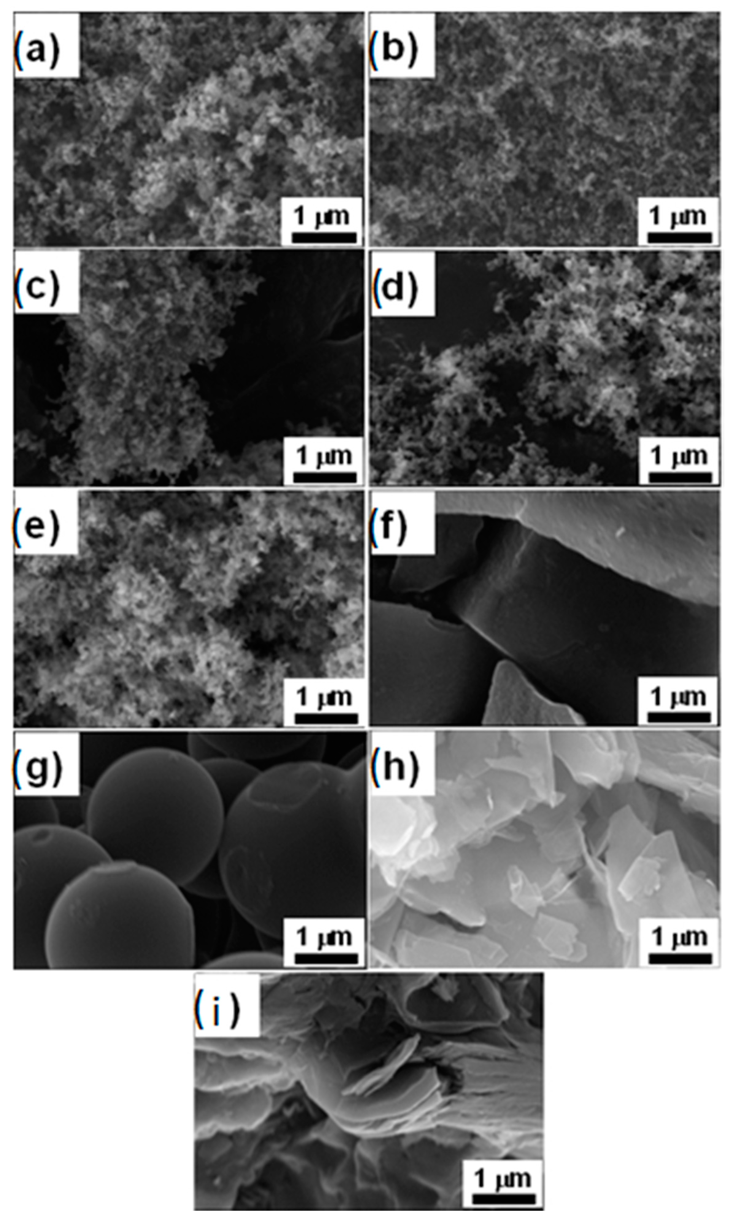
The nine carbons also have different particle size and surface morphology, observed by scanning electron microscopy, and presented in Figure 2. Their sizes range from few tens of nanometers (AB, KB1, KB2, superP, and superP-Li) to few tens of micrometers (graphite). For micrometer-sized carbons, their surface morphology is varied from smooth (splintered glassy carbon and spherical glassy carbon) to rough surfaces (graphite). The surface roughness of KS6 could be classified in between the very smooth and very rough surfaces, with its unique flake-like morphology. The specific surface areas of carbon samples are also different, as shown in the experimental part, from as low as ~4.1 m2 g−1 for graphite powder to ~1400 m2 g−1 for KB2 carbon.
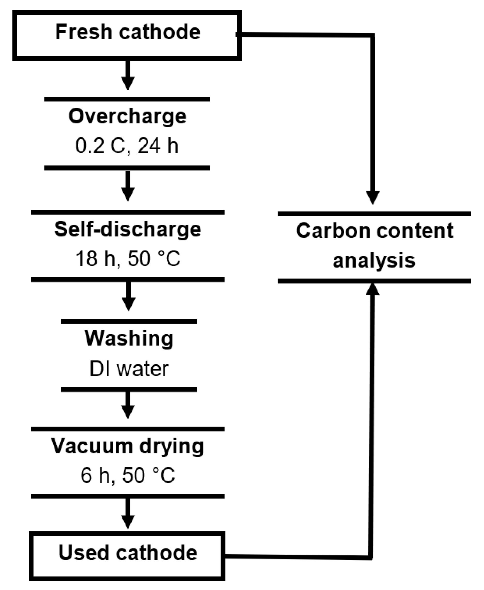
In the carbon stability test (Scheme 1), the designed cathodes contain large carbon content (15 wt%) and a minimum amount of PVdF binder (5 wt%). Due to the difference in the specific surface area of carbon conductors, each type of cathode has its own slurry preparation recipe (or amount of NMP solvent required). In particular, it is impossible to prepare the cathode with KB2 because of its very high specific surface area (~1400 m2 g−1), thus 5 wt% of PVdF is not enough to bind all particles together. Therefore, this carbon is removed from our consideration because the preparation consuming high quantities of PVDF and NMP is not considered as environmentally friendly nor economical and it requires a very long time for full evaporation of the solvent afterward. In addition, it is interesting to see that carbon distribution on the cathode made with spherical glassy carbon is not uniform, which may be because of the spherical shape and size of the spherical glassy carbon, since cathodes could be well made with splintered glassy carbon.
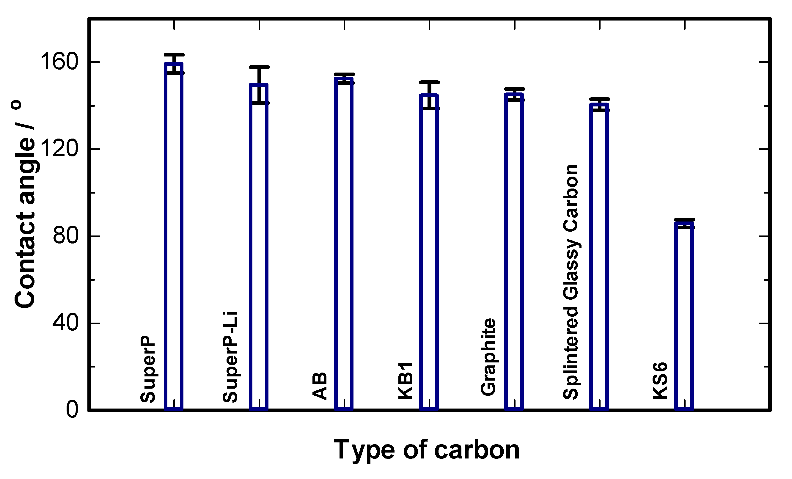
Since both the current collector (PE film) and binder (PVdF) are hydrophobic, the hydrophobicity of the carbon conductor used in the cathode composite may play an important role in defining the wettability of the cathodes. Wettability of the cathodes was measured using the contact angle technique, as shown in Figure 3. Water was used for the contact angle measurements. Advancing contact angles indicate that all the cathodes are hydrophobic except the one containing KS6. The unique flake shape of KS6 may be the key to significantly change the intrinsic hydrophobic nature of the composite electrode.
To confirm that there is no precipitated salt remaining inside the porous cathodes after washing, a blank test was performed. A number of cathodes were kept inside the batteries at open circuit voltage (OCV) conditions for 24 h at room temperature, followed by heating in an oven for 18 h at 50 °C. After the cathodes were washed thoroughly with deionized water and vacuum dried, the carbon contents of the fresh and used cathode powders were determined accurately by elemental analysis. The carbon contents of fresh and used cathodes are identical, indicating that the salt precipitation on the cathode is fully eliminated by our washing process.
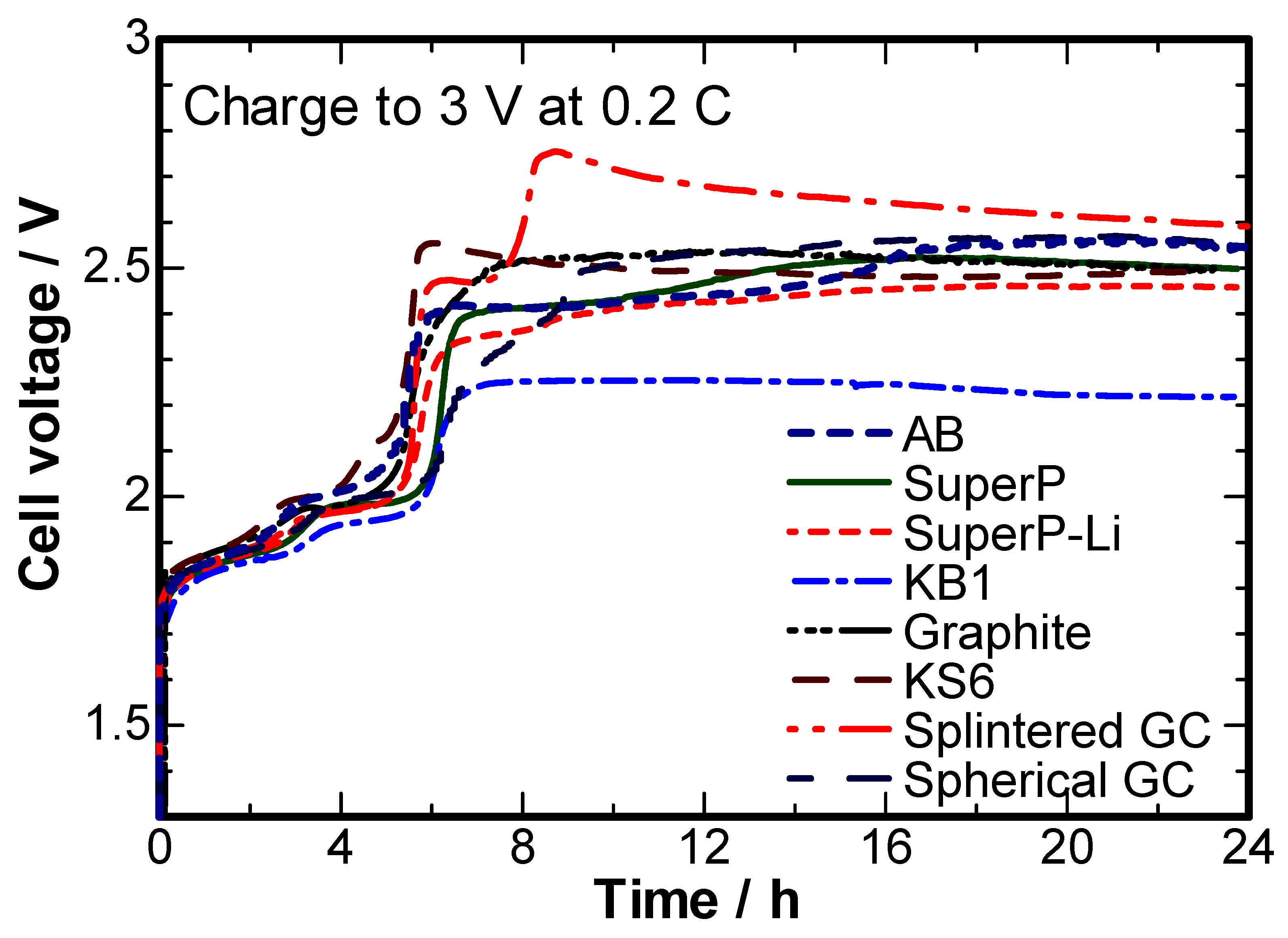
The charge profiles of cathodes with different carbon types are presented in Figure 4. In most cases, the oxygen evolution potential is about 2.5–2.6 V vs. Zn2+/Zn°. However, the KB1-containing cathode has oxygen evolution potential of about 2.25–2.3 V vs. Zn2+/Zn°. This phenomenon is related to the large specific surface area (about 800 m2 g−1) and non-graphitic structure of KB1. In general, amorphous carbons with larger surface area may host a high number of active sites for the evolution of oxygen, thus reducing the oxygen evolution voltage by lowering the reaction energy barrier. Cathodes with lower surface area and higher graphitic content (e.g., cathodes with graphite, KS-6, or superP-Li) tend to achieve higher oxygen revolution potentials. The others stand in between. The initial resistance of the graphite-containing cathode against oxidation is the best in the series.
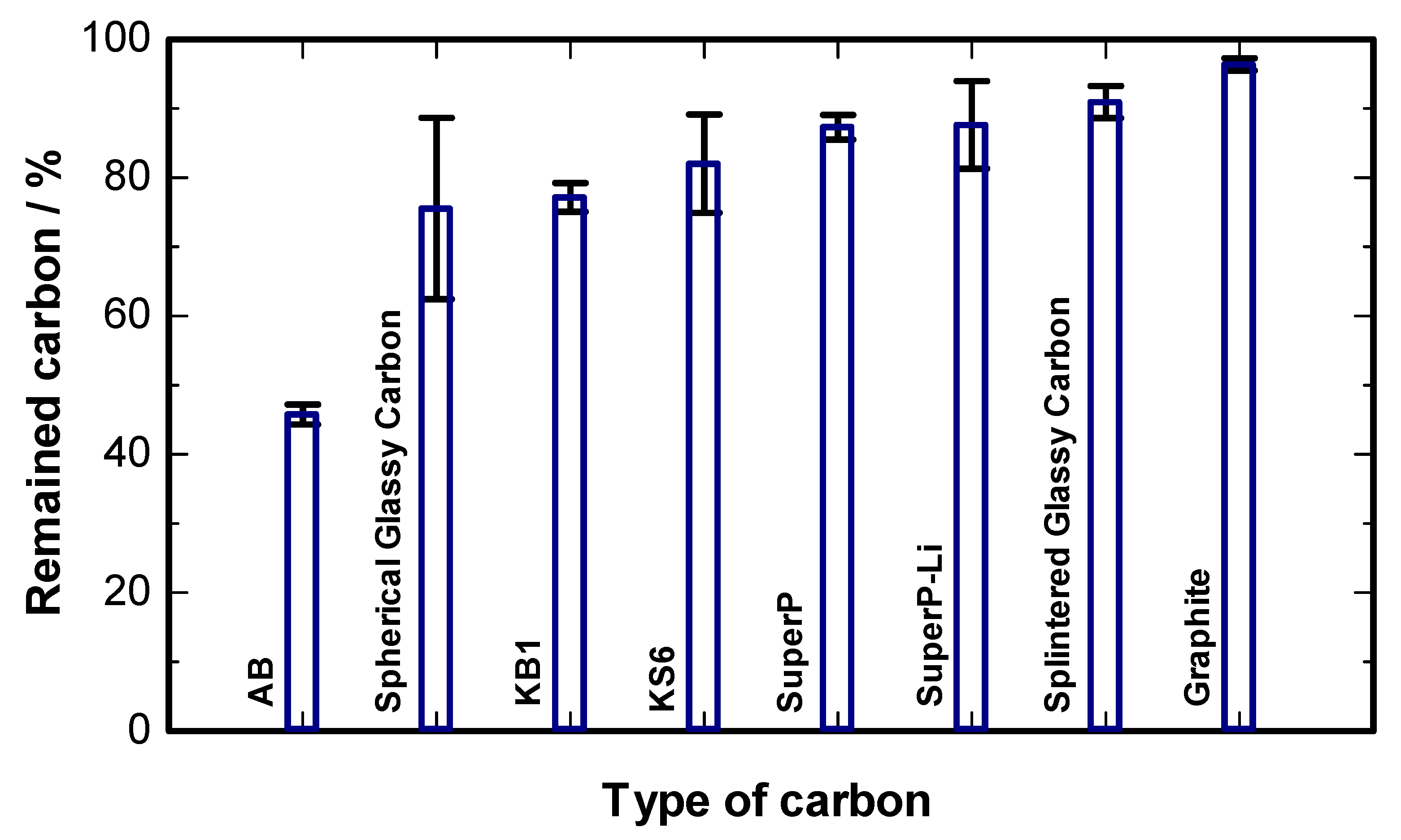
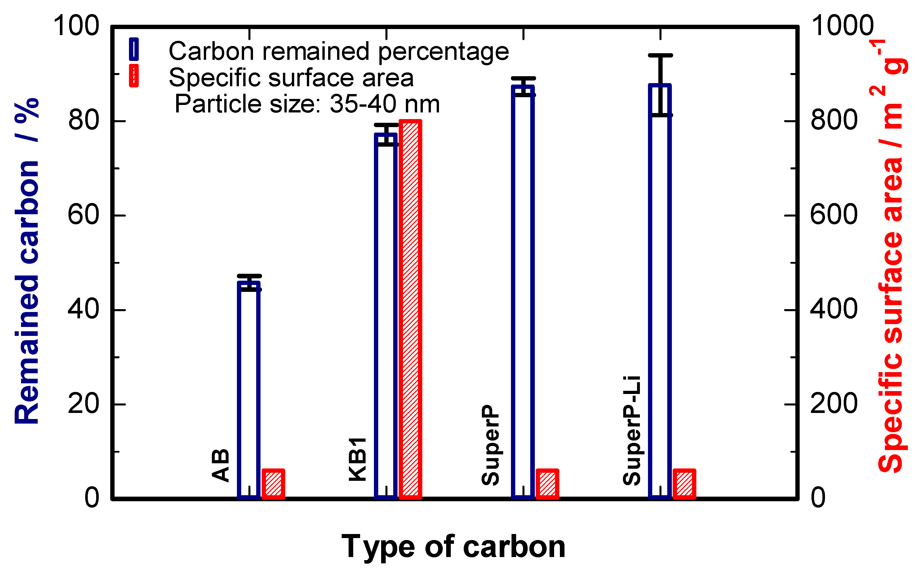
Figure 5 shows the remaining carbon percentage of cathodes using different types of carbon after the stability test. The standard deviation of the result of cathodes containing spherical glassy carbon is larger than the others. This value comes from the non-uniform carbon distribution in the cathode composite. Thus, the stability measurement of spherical glassy carbon is unreliable and should be removed from consideration. Among the characterized carbon materials, graphite is the most stable one: after the stability test, 96.4 wt% of graphite carbon remains. This is correlated with the previous results in Figure 4 that the graphite-containing cathode exhibits high initial resistance to overcharging. On the other hand, acetylene black is the least stable carbon, with a loss of up to 54.2 wt%. The self-discharge period has no significant effect on the carbon loss because carbon contents measured before and after self-discharge are similar. It is concluded that most carbon loss happens in the over-charge process, which has significantly higher current density and potential than those of the self-discharge one. Figure 6 presents the remaining carbon percentages of four types of carbon materials, which have similar particle shapes and particle sizes of ~35–40 nm: KB1, AB, superP, and superP-Li. The specific surface area of AB (~60 m2 g−1), SuperP, and SuperP-Li are at the same magnitude, and they are much smaller than that of KB1 (~800 m2 g−1). However, AB is less stable than KB1, while superP and superP-Li are more stable.
In addition, it is obvious that although AB has a similar X-ray pattern compared to superP and superP-Li, the previous one has inferior carbon stability. It is a similar case when comparing KS-6 to graphite. The stability of carbon is definitely one of the most important factors to consider for the right choice of carbon conductor for the cathode of ReHABs. Other important factors are carbon distribution within the cathode composite, the wettability of the cathode, the electronic conductivity of the carbon and the cathode.

3. Discussion

Nine different commercially available carbon materials have been used to make cathodes containing LiMn2O4 and PVdF. The physical parameters are all different. Firstly, diffraction results show that KS-6 and graphite are highly crystalline, while others are not. High-quality graphitic carbon powders exhibit a conductivity in the 103 S⋅m−1 order under pressing pressure of 5 MPa [30]. The highly pressing pressure was used to deliver sufficient contact of the powders and the electrodes during measurement. Low-crystalline synthetic acetylene black and Ketjen black have conductivity in the same magnitude with other types of carbon black and carbon nanotubes—at the 102–103 S⋅m−1 level [31,32,33]. Glassy carbon types are non-graphitic, possessing fullerene-related structures; they possess mostly sp2-bonded carbon, which justifies the high chemical and thermal stabilities [34].
The scanning electron microscopy results reveal three distinct families of carbon materials; from Figure 2a–e, the carbons are non-graphitic and possess small primary particle sizes of 35–40 nm, which are aggregated to create larger secondary particles and some levels of porosity. The surface areas of the carbons in this group are varied, while acetylene black, superP, and superP-Li have low surface area of about 60 m2⋅g−1, and carbon KB1 and KB2 exhibit 800 and 1400 m2⋅g−1. High surface area carbons are useful in fabricating cathodes with nanosized and especially low-conducting materials, such as LiFePO4, but these carbons also possess a higher number of active sites for oxidation. This renders the low potential obtained on the KB1-containing cathode in Figure 4; this will be discussed further below. The SEM images of the two glassy carbons and the two graphitic carbons are different from the first non-graphitic group. KS-6 has a loose flake-like surface vs. graphite. The spherical glassy carbon exhibits near-uniform rounded particle shape, while the splintered glassy carbon shows the large particle-type—it is, however, not a graphitic crystalline material, as confirmed by the powder diffraction method.
Pure carbon materials should be hydrophobic in nature. All carbons studied in this work exhibit high contact angles, except carbon KS-6. KS-6 is graphitic with a high surface area and contains thin flakes vs. the surface texture of graphite. In a study by Parobek and Liu, thinner flakes and graphene-like materials exhibit lower contact angles [35]. When increasing the number of graphene layers, the contact angle increases and approaches the contact angle of graphite. Additionally, the higher surface area may provide a little more adsorption of water through the slit-type openings. In general, this is good for aqueous batteries because the surface of the prepared cathodes can be more hydrophilic and have better interfacial contact with aqueous electrolytes. Many of our projects related to aqueous batteries use carbon KS-6 in the formulation of cathodes.
Figure 4 provides the responses when eight different cathodes have been overcharged to 3 V. It is noteworthy that the cathode containing KB2 could not be prepared under the same condition; therefore, it was not tested. There are two areas to be considered here. The first area is between 1.4 and 2.1 V vs. Zn2+/Zn, where the Zn/LiMn2O4 battery is functioning regularly. The second area has voltage higher than 2.1 V vs. Zn2+/Zn, where the battery is not designed to work as this area is the overcharging zone. In the first area, the cathodes made from KB1, superP, or superP-Li take more than 5 h to be charged completely, while the cathodes containing AB, KS-6, graphite, or splintered glassy carbon take less charging time. The extra charge time needed for some cathodes may have been spent on side reactions (i.e., oxygen revolution and carbon oxidation). We should see two distinct plateaus corresponding to the two-step deintercalation of lithium ion out of the LiMn2O4 lattice. In Figure 4, however, the second plateau at higher voltage is varied vs. the type of cathode. Some carbons such as KB1 and superP-Li may be more susceptible to oxidation than others. When the potential exceeds 2.1 V, the cathodes made from graphitic and glassy carbons are generally more resistance toward oxidation than others. This may be due to the high concentration of sp2 carbon and higher resistance to chemical attack. Among the non-graphitic and non-glassy carbon, only AB shows decent electrochemical resistance toward oxidation at potential lower than 2.1 V. During overcharging, the AB-containing cathode just reaches 2.4 V, which is lower than the graphitic and glassy carbon-containing cathode. However, microanalysis of the post run electrode shows a huge decrease in carbon concentration of the AB electrode vs. others. This is still elusive while it is reasonable that the graphitic and glassy carbons may show higher retention. The retention of KS-6 is lower than graphite. This may be due to the higher surface area and better wettability of KS-6 vs. graphite. Furthermore, the KS-6 containing cathode requires less charging time than the other. This further confirms that KS-6 is a good choice for blending with LiMn2O4 during cathode fabrication.

4. Materials and Methods

4.1. Physical Characterizations

Nine different commercially available carbon materials were investigated, including: acetylene black (AB, 35–40 nm, ~60 m2 g−1, MTI, Richmond, VA, USA), superP (~40 nm, 60 m2 g−1, Timcal, Bodio, Switzerland), superP-Li (~40 nm, 60 m2 g−1, Timcal), Ketjen Black EC-300J (KB1, 35–40 nm, ~800 m2 g−1, Akzo Nobel Surface Chemistry LLC, Chicago, IL, USA), Ketjen Black EC-600D (KB2, 35–40 nm, ~1400 m2 g−1, Akzo Nobel Surface Chemistry LLC), graphite powder (~20 μm, ~4.1 m2 g−1, MTI), spherical glassy carbon (0.4–12 μm, SPI-Chem, West Chester, PA, USA), splintered glassy carbon (0.4–12 μm, SPI-Chem), and KS6 (~3 μm, 20 m2 g−1, Timcal). Their specific surface areas and porosity were characterized by the accelerated surface area and a porosimetry analyzer (ASAP2020, Micromeritics, Norcross, GA, USA) using a 20-point nitrogen adsorption and desorption program. The crystalline phase of all samples was studied by X-ray diffraction (XRD, D8 Discover, Brüker, Billerica, MA, USA) technique equipped with Cu-Kα radiation, with a scan speed of 1° per minute, ranging from 10° to 100°. The composite surface morphology was examined using Field Emission Scanning Electron Microscopy (FE-SEM, Leo-1550, Zeiss, Oberkochen, Germany).
Wettability of the cathodes containing different carbons was measured by contact angle technique. The contact angle measurements were carried out by forming an unconstrained sessile drop of pure water on a flat surface of the cathode material [36,37]. The entire system was placed on a vibration-free table. The images of the sessile drop were captured by a charge-coupled device (CCD) camera overtime and digitized for analysis. Axisymmetric drop shape analysis (ADSA) was used to determine contact angles from the shape of the sessile drops. Assuming the experimental drop profile to be axisymmetric and Laplacian, ADSA finds the theoretical profile that best matches the profile extracted from the image of a real drop. From the best match, the liquid–vapor interfacial tension, contact angle, volume and surface area of the drop, and the three-phase contact radius are determined [38,39,40].

4.2. Carbon Stability Testing Procedure

The flow chart of the carbon stability test is shown in Figure 1. Each cathode was prepared by casting the slurry containing commercial LiMn2O4 (MTI), carbon, and polyvinylidene fluoride (PVdF, Kynar®, HSV900) (80:15:5 wt%) in 1-methyl-2-pyrrolidinone (NMP, Sigma-Aldrich, St. Louis, MO, USA, ≥99.5% purity) on a conductive polyethylene (PE, All-Spec Industries, Wilmington, DE, USA) film, followed by vacuum drying at 50 °C for 12 h. Disks of 12 mm in diameter were cut (typical active material loading of 6.6 mg cm−2) and soaked in the electrolyte solution under vacuum for 30 min. Zinc disks 12 mm in diameter (Rotometals, ~99.6% purity, titanium added) were polished by 1-micron polish powder (Buehler), washed by deionized water, and then, used as anodes. The electrolyte was prepared by dissolving 1 M ZnSO4.7H2O (Alfa Aesar, Tewksbury, MA, USA, ≥98% purity) and 2 M Li2SO4 (Sigma-Aldrich, ≥98% purity) in deionized water and pH was adjusted to 4.00 ± 0.05 using 0.1 M H2SO4 solution or LiOH solution. An absorbed glass mat (AGM, NSG Corporation, Tokyo, Japan) was used as the separator. The carbon stability test was conducted using two-electrode Swagelok-type cells. The cells were charged galvanostatically on a multichannel battery tester (BTS-5V5mA, Neware, Shenzhen, China) at 0.2 C (1 C = 130 mA g−1) for 24 h, and then, kept in an oven at 50 °C for 18 h. Applied currents and specific capacities were calculated based on the weight of LiMn2O4 in the cathode. Oxygen evolution will occur at the overcharge stage [6,7] because the applied potential is higher than the potential required for oxygen revolution, which leads to the oxidation of the carbon conductor.
After that, the cells were cooled down to room temperature and disassembled. The cathodes were washed thoroughly by deionized water, and then, vacuum dried at 50 °C for 6 h. Carbon contents of pristine and used cathodes were determined by an elemental analyzer (CHNS, Vario Micro Cube, Elementar, Langenselbold, Germany). The remaining carbon percentages were calculated as following:
C remained ,   % = C actual ,   % C ideal ,   % 100 %
In which, Cactual,% is the carbon content measured after overcharge at ambient temperature and self-discharge at elevated temperature, and Cideal,% is calculated from the carbon content of the pristine sample, assuming that there is no carbon lost and all of the LiMn2O4 was converted to Mn2O4.

5. Conclusions

In this study, a simple method to evaluate carbon stability in a typical aqueous rechargeable lithium battery cathode is introduced. By employing this method, it is concluded that the electrochemical stability of carbon when the cathode is overcharged is strongly related to the its physical properties, such as crystallinity, morphology, specific surface area, particle size, and wettability of the cathodes. Further development of simple evaluation methods is helpful in the optimization and commercialization of the aqueous rechargeable battery systems.

Author Contributions

Conceptualization, T.N.L.D. and P.C.; methodology, T.N.L.D. and S.M.I.S.; formal analysis, T.N.L.D. and T.K.A.H.; T.N.L.D.; writing—original draft preparation, T.N.L.D.; writing—review and editing T.N.L.D. and T.K.A.H.; P.C. supervision. All authors have read and agreed to the published version of the manuscript.

Funding

This research was funded by Mitacs, grant number IT06145, IT06460.

Conflicts of Interest

The authors declare no conflict of interest. The funders had no role in the design of the study; in the collection, analyses, or interpretation of data; in the writing of the manuscript, or in the decision to publish the results.

References

  1. Abou-Rjeily, J.; Bezza, I.; Laziz, N.A.; Autret-Lambert, C.; Sougrati, M.T.; Ghamouss, F. High-rate cyclability and stability of LiMn2O4 cathode materials for lithium-ion batteries from low-cost natural β−MnO2. Energy Storage Mater. 2020, 26, 423–432. [Google Scholar] [CrossRef]
  2. Yu, X.L.; Deng, J.J.; Yang, X.; Li, J.; Huang, Z.-H.; Li, B.H.; Kang, F.Y. A dual-carbon-anchoring strategy to fabricate flexible LiMn2O4 cathode for advanced lithium-ion batteries with high areal capacity. Nano Energy 2020, 67, 104256. [Google Scholar] [CrossRef]
  3. Cai, Z.F.; Ma, Y.Z.; Huang, X.N.; Yan, X.H.; Yu, Z.X.; Zhang, S.H.; Song, G.S.; Xu, Y.L.; Wen, C.; Yang, W.D. High electrochemical stability Al-doped spinel LiMn2O4 cathode material for Li-ion batteries. J. Energy Storage 2020, 27, 101036. [Google Scholar] [CrossRef]
  4. Abbas, S.M.; Hashem, A.M.; Abdel-Ghany, A.E.; Ismail, E.H.; Kotlár, M.; Winter, M.; Li, J.; Julien, C.M. Ag-Modified LiMn2O4 Cathode for Lithium-Ion Batteries: Coating Functionalization. Energies 2020, 13, 5194. [Google Scholar] [CrossRef]
  5. Palaniyandy, N.; Rambau, K.; Mysyoka, N.; Ren, J.W. A Facile Segregation Process and Restoration of LiMn2O4 Cathode Material From Spent Lithium-Ion Batteries. J. Electrochem. Soc. 2020, 167, 090510. [Google Scholar] [CrossRef]
  6. Zhang, H.; Liu, X.; Li, H.; Hasa, D.; Passerini, S. Challenges and Strategies for High-Energy Aqueous Electrolyte Rechargeable Batteries. Angew. Chem. Int. Ed. 2020, 59, 2–21. [Google Scholar] [CrossRef]
  7. Luo, J.-Y.; Cui, W.-J.; He, P.; Xia, Y.Y. Raising the cycling stability of aqueous lithium-ion batteries by eliminating oxygen in the electrolyte. Nat. Chem. 2010, 2, 760–765. [Google Scholar] [CrossRef]
  8. Tang, W.; Zhu, Y.S.; Hou, Y.Y.; Liu, L.L.; Wu, Y.P.; Loh, K.P.; Zhang, H.P.; Zhu, K. Aqueous rechargeable lithium batteries as an energy storage system of superfast charging. Energy Environ. Sci. 2013, 6, 2093–2104. [Google Scholar] [CrossRef]
  9. Miyazaki, K.; Shimada, T.; Ito, S.; Yokoyama, Y.; Fukutsuka, T.; Abe, T. Enhanced resistance to oxidative decomposition of aqueous electrolytes for aqueous lithium-ion batteries. Chem. Commun. 2016, 52, 4979–4982. [Google Scholar] [CrossRef] [Green Version]
  10. Nair, V.S.; Sreejith, S.; Joshi, H.; Zhao, Y.L.; West, A.; Madhavi, S. The fabrication of LiMn2O4 and Na1.16V3O8 based full cell aqueous rechargeable battery to power portable wearable electronics devices. Mater. Des. 2016, 93, 291–296. [Google Scholar] [CrossRef]
  11. Gordon, D.; Wu, M.Y.; Ramanujapuram, A.; Benson, J.; Lee, J.T.; Magasinski, A.; Nitta, N.; Huang, C.; Yushin, G. Enhancing Cycle Stability of Lithium Iron Phosphate in Aqueous Electrolytes by Increasing Electrolyte Molarity. Adv. Energy Mater. 2016, 6, 1501805. [Google Scholar] [CrossRef]
  12. Sun, D.; Tang, Y.; He, K.; Ren, Y.; Liu, S.; Wang, H. Long-lived Aqueous Rechargeable Lithium Batteries Using Mesoporous LiTi2(PO4)3@C Anode. Sci. Rep. 2015, 5, 17452. [Google Scholar] [CrossRef] [PubMed] [Green Version]
  13. Noerochim, L.; Yurwendra, A.O.; Susanti, D. Effect of carbon coating on the electrochemical performance of LiFePO4/C as cathode materials for aqueous electrolyte lithium-ion battery. Ionics 2016, 22, 341–346. [Google Scholar] [CrossRef]
  14. Zeng, X.Y.; Liu, Q.B.; Chen, M.F.; Leng, L.M.; Shu, T.; Du, L.; Song, H.Y.; Liao, S.J. Electrochemical Behavior of Spherical LiFePO4/C Nanomaterial in Aqueous Electrolyte, and Novel Aqueous Rechargeable Lithium Battery with LiFePO4/C anode. Electrochim. Acta 2015, 177, 277–282. [Google Scholar] [CrossRef]
  15. Sun, D.; Jiang, Y.F.; Wang, H.Y.; Yao, Y.; Xu, G.Q.; He, K.J.; Liu, S.Q.; Tang, Y.; Liu, Y.N.; Huang, X.B. Advanced aqueous rechargeable lithium battery using nanoparticulate LiTi2(PO4)3/C as a superior anode. Sci. Rep. 2015, 5, 10733. [Google Scholar] [CrossRef]
  16. Arun, N.; Aravindan, V.; Ling, W.C.; Madhavi, S. Importance of nanostructure for reversible Li-insertion into octahedral sites of LiNi0.5Mn1.5O4 and its application towards aqueous Li-ion chemistry. J. Power Sources 2015, 280, 240–245. [Google Scholar] [CrossRef]
  17. Yan, J.; Wang, J.; Liu, H.; Bakenov, Z.; Gosselink, D.; Chen, P. Rechargeable hybrid aqueous batteries. J. Power Sources 2012, 216, 222–226. [Google Scholar] [CrossRef]
  18. Yuan, G.H.; Bai, J.T.; Doan, T.N.L.; Chen, P. Synthesis and electrochemical investigation of nanosized LiMn2O4 as cathode material for rechargeable hybrid aqueous batteries. Mater. Lett. 2014, 137, 311–314. [Google Scholar] [CrossRef]
  19. Yuan, G.H.; Bai, J.T.; Doan, T.N.L.; Chen, P. Synthesis and electrochemical properties of LiFePO4/graphene composite as a novel cathode material for rechargeable hybrid aqueous battery. Mater. Lett. 2015, 158, 248–251. [Google Scholar] [CrossRef]
  20. Han, Z.X.; Askhatova, D.; Doan, T.N.L.; Hoang, T.K.A.; Chen, P. Experimental and mathematical studies on cycle life of rechargeable hybrid aqueous batteries. J. Power Sources 2015, 279, 238–245. [Google Scholar] [CrossRef]
  21. Zhu, X.; Doan, T.N.L.; Yu, Y.; Tian, Y.; Sun, K.E.K.; Zhao, H.B.; Chen, P. Enhancing rate performance of LiMn2O4 cathode in rechargeable hybrid aqueous battery by hierarchical carbon nanotube/acetylene black conductive pathways. Ionics 2016, 22, 71–76. [Google Scholar] [CrossRef]
  22. Lu, C.Y.; Hoang, T.K.A.; Doan, T.N.L.; Zhao, H.B.; Pan, R.; Yang, L.; Guan, W.S.; Chen, P. Rechargeable hybrid aqueous batteries using silica nanoparticle doped aqueous electrolytes. Appl. Energy 2016, 170, 58–64. [Google Scholar] [CrossRef]
  23. Gallagher, K.G.; Fuller, T.F. Kinetic model of the electrochemical oxidation of graphitic carbon in acidic environments. Phys. Chem. Chem. Phys. 2009, 11, 11557–11567. [Google Scholar] [CrossRef] [PubMed]
  24. Liu, H.J.; Xu, Q.; Yan, C.W.; Qiao, Y.L. Corrosion behavior of a positive graphite electrode in vanadium redox flow battery. Electrochim. Acta 2011, 56, 8783–8790. [Google Scholar] [CrossRef]
  25. Dekanski, A.; Stevanović, J.; Stevanović, R.; Nikolić, B.Z.; Jovanović, V.M. Glassy carbon electrodes I. Characterization and electrochemical activation. Carbon 2001, 39, 1195–1205. [Google Scholar] [CrossRef]
  26. Hassel, O. Ueber die Kristallstruktur des Graphits. Z. Phys. 1924, 25, 317–337. [Google Scholar] [CrossRef]
  27. Lipson, H.; Stokes, A.R. The Structure of Graphite. Proc. R. Soc. Math. Phys. Eng. Sci. 1942, 181, 101–105. [Google Scholar]
  28. Biscoe, J.; Warren, B.E. An X-ray Study of Carbon Black. J. Appl. Phys. 1942, 13, 364. [Google Scholar] [CrossRef]
  29. Harris, P.J.F. Fullerene-related structure of commercial glassy carbons. Phisolophical Mag. 2004, 84, 3159–3167. [Google Scholar] [CrossRef] [Green Version]
  30. Marinho, B.; Ghislandi, M.; Tkalya, E.; Koning, C.E.; de With, G. Electrical conductivity of compacts of graphene, multi-wall carbon nanotubes, carbon black, and graphite powder. Powder Technol. 2012, 221, 351–358. [Google Scholar] [CrossRef]
  31. Giet, C. Acetylene Black with High Electrical Conductivity and High Absorptive Power. US Patent US4279880A, 21 July 1981. [Google Scholar]
  32. Rimbu, G.A.; Stamatin, I.; Jackson, C.L.; Scott, K. The Morphology Control of Poloyaniline as Conducting Polymer in Fuel Cell Technology. J. Optoelectron. Adv. Mater. 2006, 8, 670–674. [Google Scholar]
  33. Cho, I.; Choi, J.; Kim, K.; Ryou, M.-H.; Lee, Y.M. A comparative investigation of carbon black (Super-P) and vapor-grown carbon fibers (VGCFs) as conductive additives for lithium-ion battery cathodes. RSC Adv. 2015, 5, 95073–95078. [Google Scholar] [CrossRef]
  34. Jurkiewicz, K.; Pawlyta, M.; Burian, A. Structure of Carbon Materials Explored by Local Transmission Electron Microscopy and Global Powder Diffraction Probes. J. Carbon Res. 2018, 4, 68. [Google Scholar] [CrossRef] [Green Version]
  35. Parobek, D.; Liu, H.T. Wettability of graphene. 2D Mater. 2015, 2, 032001. [Google Scholar] [CrossRef]
  36. Kwok, D.Y.; Neumann, A.W. Contact Angle Measurement and Contact Angle Interpretation. Adv. Colloid Interface Sci. 1999, 81, 167–249. [Google Scholar] [CrossRef]
  37. Tavana, H.; Lam, C.N.C.; Friedel, P.; Grundke, K.; Kwok, D.Y.; Hair, M.L.; Neumann, A.W. Contact angle measurements with liquids consisting of bulky molecules. J. Colloid Interface Sci. 2004, 279, 493–502. [Google Scholar] [CrossRef]
  38. Tavana, H.; Neumann, A.W. Recent progress in the determination of solid surface tensions from contact angles. Adv. Colloid Interface Sci. 2007, 132, 1–32. [Google Scholar] [CrossRef]
  39. Del Río, O.I.; Neumann, A.W. Axisymmetric drop shape analysis: Computational methods for the measurement of interfacial properties from the shape and dimensions of pendant and sessile drops. J. Colloid Interface Sci. 1997, 196, 136–147. [Google Scholar]
  40. Saad, S.M.I.; Policova, Z.; Neumann, A.W. Design and accuracy of pendant drop methods for surface tension measurement. Colloids Surf. Phys. Eng. Asp. 2011, 384, 442–452. [Google Scholar] [CrossRef]
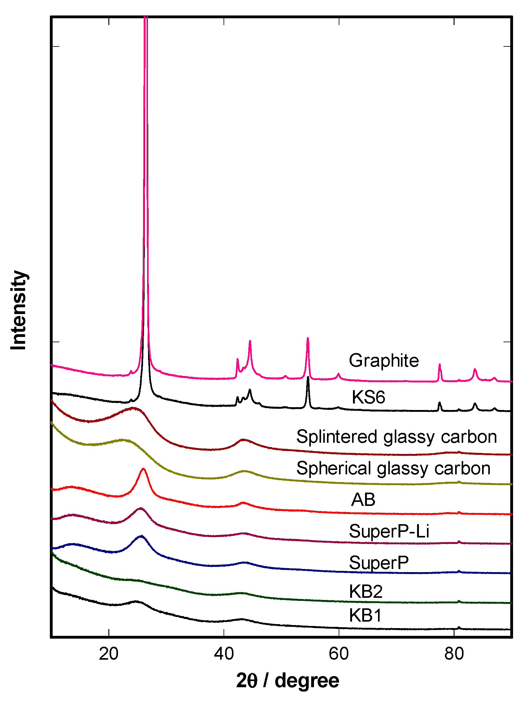
Figure 1. XRD patterns of different types of carbon.
Batteries 06 00059 g001
Figure 2. SEM images of (a) AB, (b) KB1, (c) KB2, (d) SuperP, (e) SuperP-Li, (f) splintered glassy carbon, (g) spherical glassy carbon, (h) KS6, and (i) graphite. Magnification: ×20,000.
Batteries 06 00059 g002
Scheme 1. Flow chart of the carbon stability test for a LiMn2O4 cathode.
Batteries 06 00059 sch001
Figure 3. Advancing contact angle measurement of water on the cathodes using different types of carbon.
Batteries 06 00059 g003
Figure 4. Charge profiles of different types of carbon.
Batteries 06 00059 g004
Figure 5. Remaining carbon percentage of cathodes using different types of carbon after the carbon stability test.
Batteries 06 00059 g005
Figure 6. Remaining carbon percentage of cathodes using four types of carbon after the carbon stability test. Those carbons have similar particle shape and size (35–40 nm).
Batteries 06 00059 g006
Publisher’s Note: MDPI stays neutral with regard to jurisdictional claims in published maps and institutional affiliations.