Article

Glycine-Nitrate Process for Synthesis of Na3V2(PO4)3 Cathode Material and Optimization of Glucose-Derived Hard Carbon Anode Material for Characterization in Full Cells

1
Institute of Chemistry, University of Tartu, Ravila 14a, 50411 Tartu, Estonia
2
Institute of Ecology and Earth Sciences, University of Tartu, Ravila 14a, 50411 Tartu, Estonia
*
Author to whom correspondence should be addressed.
Batteries 2019, 5(3), 56; https://doi.org/10.3390/batteries5030056
Submission received: 6 June 2019 / Revised: 3 July 2019 / Accepted: 11 July 2019 / Published: 2 August 2019
(This article belongs to the Special Issue Future Battery Concepts)

Abstract

:
Cost-effective methods need to be developed to lower the price of Na-ion battery (NIB) materials. This paper reports a proof-of-concept study of using a novel approach to the glycine-nitrate process (GNP) to synthesize sodium vanadium phosphate (Na3V2(PO4)3 or NVP) materials with both high-energy (102 mAh g−1 at C/20) and high-power characteristics (60 mAh g−1 at 20 C). Glucose-derived hard carbons (GDHCs) were optimized to reduce both sloping and irreversible capacity. The best results were achieved for electrodes with active material heat treated at 1400 °C and reduced Super P additive. Sloping region capacity 90 mAh g−1, irreversible capacity 47 mAh g−1, discharge capacity 272 mAh g−1 (of which plateau 155 mAh g−1) and 1st cycle coulombic efficiency (CE) 85% were demonstrated. GDHC||NVP full cell achieved 80 mAh g−1 (reversible) by NVP mass out of which 60 mAh g−1 was the plateau (3.4 V) region capacity. Full cell specific energy and energy density reached 189 Wh kg−1 and 104 Wh dm−3, respectively. After 80 cycles, including rate testing from C/20 to 10 C, the cell cycled at 65 mAh g−1 with 99.7% CE. With further optimization, this method can have very high industrial potential.

Graphical Abstract

1. Introduction

Sodium-ion batteries (NIBs) are considered as an alternative to lithium-ion batteries (LIBs), especially in large-scale stationary applications. It does not make sense to use potentially scarce lithium (Li) resources [1] in applications where energy density is not a paramount issue. Sodium (Na) is 1000 times more abundant in the Earth’s crust than Li [2] and is evenly distributed unlike Li, which is concentrated in South America [3]. Another issue that is plaguing battery material suppliers is the use of cobalt (Co) in all high-energy Li-ion cells. Cobalt is the by-product of copper (Cu) and nickel (Ni) production [4] and issues have been raised around the ethics of its mining [5].
Sodium vanadium phosphate (Na3V2(PO4)3 or NVP) is a NASICON (NA Super Ionic CONductor)-type material [6] with a high and very flat potential plateau at 3.4 V and theoretical capacity of 118 mAh g−1. The reaction in the NVP positive electrode is based on a two-electron reaction of Na3V2(PO4)3 ⇄ NaV2(PO4)3 + 2Na+ + 2e [7]. NVP has an open NASICON framework made of VO6 octahedra and PO4 tetrahedra between which Na ions can diffuse through interstitial sites and 2 Na+ can be reversibly extracted [8,9]. Although, NVP has good ionic conductivity, its rate capability can be limited by relatively low electronic conductivity. Reducing particle size and adding a conductive coating around the particles are common methods for achieving high-power characteristics [10].
Superb high-power performance (71.7 mAh g−1 at 99.3 C) is reported in the literature, which was achieved through careful particle morphology optimization [11]. NVP has good electrochemical performance and low manufacturing costs, which sets the price of performance at $3.7 Wh–1 kg [12]. Its fluorinated analogue with higher energy density ranks at $3.5 Wh–1 kg.
The glycine-nitrate process (GNP) is a sub-category of solution combustion synthesis (SCS) methods, which are based on fast redox reactions between an oxidant (commonly nitrates) and a fuel (organic substances) in the presence of metal ions [13]. Effectively, SCS is a combination of sol-gel [14] and propellant chemistry [15]. There are many advantages to using the GNP. Firstly, all the reactants will be dissolved, which ensures intimate mixing of the ions and is crucial to ensure formation of pure phases [16]. Secondly, the reaction is very quick, which reduces time for particle agglomeration and enables the production of small particles [17] that are necessary for high-power density battery cells. Thirdly, this method can be turned into a flow process, which makes it industrially scalable [13]. The GNP and its variations have been used by the solid-oxide fuel cell research community [13,17,18] and to some extent by the battery community to synthesize and study materials like NaTi3(PO4)3 [19], Li(Ni1/3Mn1/3Co1/3-xNax)O2 [20], LiNi1/3Co1/3Mn1/3O2 (urea as fuel) [21], Li4Ti5O12 (lactic acid as fuel) [22], substituted Na0.44MnO2 bronzes [23,24,25,26], Na0.44MnO2 (urea as fuel) [27] and ZnFe2O4 [28]. This paper is the first report to our knowledge that successfully utilizes the GNP method to produce a NVP cathode material and characterize it in half and full cells.

2. Materials and Methods

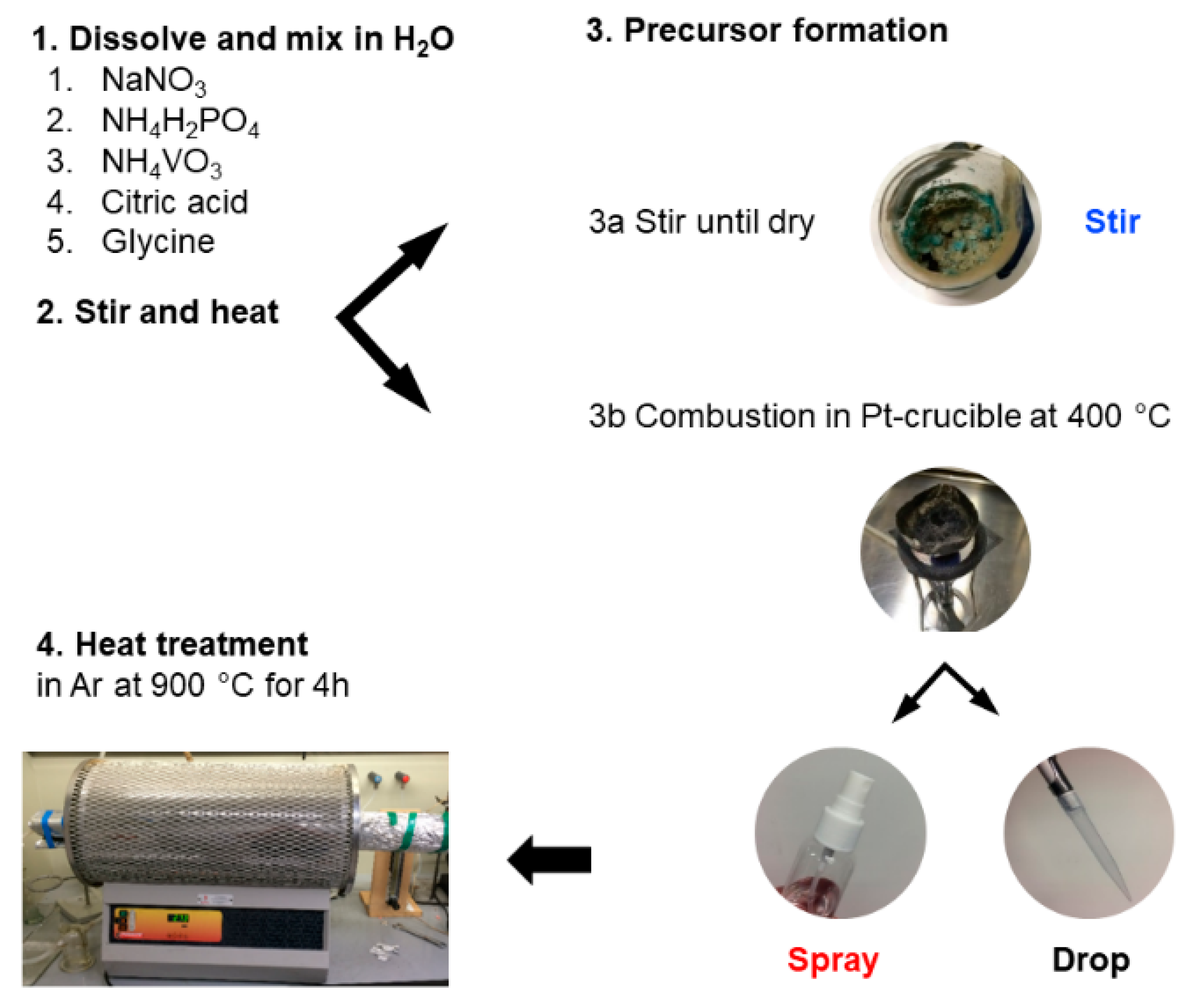
2.1. Synthesis of Na3V2(PO4)3

Stoichiometric amounts of NaNO3 (≥99%, Honeywell, Charlotte, NC, USA), NH4H2PO4 (99.9%, Acros, Morris Plains, NJ, USA) and NH4VO3 (>99.0%, Honeywell, Charlotte, NC, USA) were dissolved in deionized water along with varying amounts of citric acid (CA, >99.5%, Sigma-Aldrich, St. Louis, MO, USA) and glycine (G, ≥99%, Sigma, St. Louis, MO, USA). Exact amounts used are summarized in Table 1 and the overall schema depicted in Scheme 1. Citric acid acts as both fuel for combustion and as a complexing agent that helps dissolve NH4VO3. Glycine is a common fuel used in nitrate combustion reactions [18,29,30], which can also serve as a precursor to carbon shell formation around NVP particles.
The resulting mixture was stirred and heated at 90 °C to remove excess water and produce a viscous gel. Three different approaches to form a precursor were employed from this point onward (Scheme 1). Option 1—the viscous solution was heated in the beaker until a soufflé-like foam was formed, denoted as NVP-stir. According to Wang et al. [31] a spontaneous combustion of the gel should have happened, but we did not observe such an effect. Option 2—the viscous solution was dropped onto a hot Pt-crucible (400 °C, heated with a natural gas flame), denoted as NVP-drop. Option 3—the viscous solution was sprayed onto the Pt-crucible using a bottle spray, denoted as NVP-spray. The precursor materials were thereafter ball-milled for 2 h at 300 rpm after which the mixture was heat-treated in a quartz tube furnace at 900 °C (ramp rate 10 °C min−1) under argon (grade 5.0, AS Eesti AGA, Tallinn, Estonia) flow (900 mL min−1) for 4 h. Efforts were made to scale up the synthesis and produce bigger batches of the material using the spray method. The first experiment was a scale-up of the NVP-spray method, denoted as spray-2 and the second was a slight modification of spray-2 in which no glucose was added to the precursor, denoted as spray-3.

2.2. Synthesis of Hard Carbons

The glucose derived hard carbon (GDHC) synthesis was a modification of our previous method [32,33] (for synthesizing GDHC 1100) and was carried out in two steps. The hydrothermal carbonization (HTC) of 2 M D-(+)-glucose (≥99.5% purity, Sigma, St. Louis, MO, USA) solution in H2O (200 ml, Milli-Q+,18.2 MΩ cm, Millipore, Burlington, MA, USA) was carried out in a high-pressure reactor (Büchi limbo, volume 285 mL) at 200 °C for 24 h. Thereafter, the carbonaceous material was collected and washed multiple times with Milli-Q+ water and dried overnight in a vacuum oven (Vaciotem-TV) at 120 °C and 50 mbar. The dried carbonaceous material was then pyrolyzed in an alumina tube reactor at temperatures from 1400 °C to 1600 °C under Ar flow for 2 h using a heating ramp rate of 4 °C min−1 [32].

2.3. Physical Characterization

Structural and crystallographic parameters were obtained from powder diffraction data using the Bruker D8 Advanced diffractometer (Billerica, MA, USA) with Ni filtered CuKα radiation (λ = 1.5406 Å), 0.3° divergence slit, two 2.5° Soller slits and LynxEye line detector. XRD patterns were analyzed using Topas software (Bruker, Billerica, MA, USA) and the double-Voigt approach was applied for fitting the patterns. SEM micrographs were acquired using the ZEISS EVO 15MA microscope (Oberkochen, Germany).

2.4. Electrode Preparation and Cell Assembly

The electrode active materials were mixed with Super P (Alfa Aesar, Haverhill, MA, USA) and polyvinylidene difluoride (PVDF, MW = 534 000, Aldrich, St. Louis, MO, USA) in a 75:15:10 weight ratio and stirred overnight using N-methyl-2-pyrrolidone (NMP, Sigma-Aldrich, St. Louis, MO, USA, 99.5%) as the solvent. Some GDHC electrodes were prepared in 85:4:11, denoted as GDHC b. The resulting mixture was cast onto aluminum foil (MTI, thickness 15 µm) using the tape casting technique. The cast electrodes were dried under vacuum at 120 °C for 12 h. Electrode mass loadings were 1.6–1.8 mg cm−2 and 4.3–4.5 mg cm−2 for GDHC and NVP electrodes, respectively. The electrochemical performance was evaluated at 23 ± 0.5 °C in 2-electrode setup using coin cells (Hohsen, Tokyo, Japan, 2032) and sodium metal (99.8%, Acros, Morris Plains, NJ, USA) as the counter electrode. The following salt and solvents were used in the tested electrolytes: NaPF6 (99%, Alfa Aesar, Haverhill, MA, USA), ethylene carbonate (EC, 99%, Sigma-Aldrich) and propylene carbonate (PC, 99.7%, Sigma-Aldrich, St. Louis, MO, USA). EC and PC were mixed in 1:1 volume ratio. Measurements were carried out in 1 M NaPF6 EC:PC (1:1) solutions. Glass fiber separators (EL-Cell GmbH, Hamburg, Germany) with thicknesses 1.55 mm and 0.26 mm were used in half cell and full cell measurements, respectively. All test cells were assembled inside an Ar-filled glove box were O2 and H2O content was less than 0.1 ppm.

2.5. Electrochemical Experiments

Electrochemical experiments were carried out using the PMC–1000 potentiostat/galvanostat/frequency response analyzer (Princeton Applied Research, Oak Ridge, TN, USA). The half and full cells were evaluated using the galvanostatic charging/discharging (GCD) method. Capacities are expressed per active material mass in the electrode in half cells and per NVP active material mass in full cells. Full cell energy was calculated by integrating the area under galvanostatic discharge profiles. The calculated energy was divided by active materials’ mass in the cathode and anode or volume calculated from coating thicknesses and electrode geometric areas to retrieve specific energy and energy density, respectively. It must be mentioned that the electrodes have not been fully optimized for maximal full cell performance, which is why active material masses are used for these calculations.

3. Results and Discussion

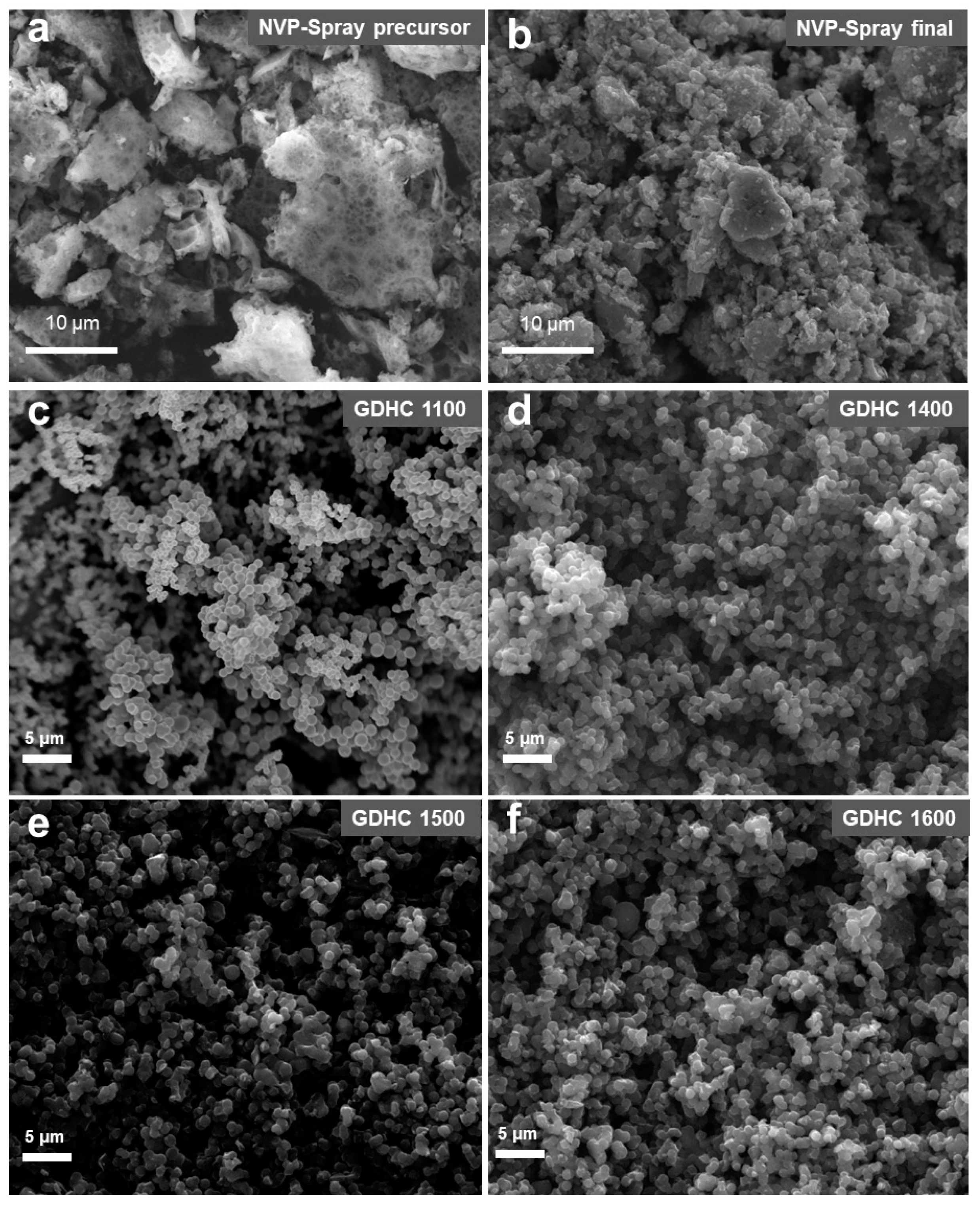
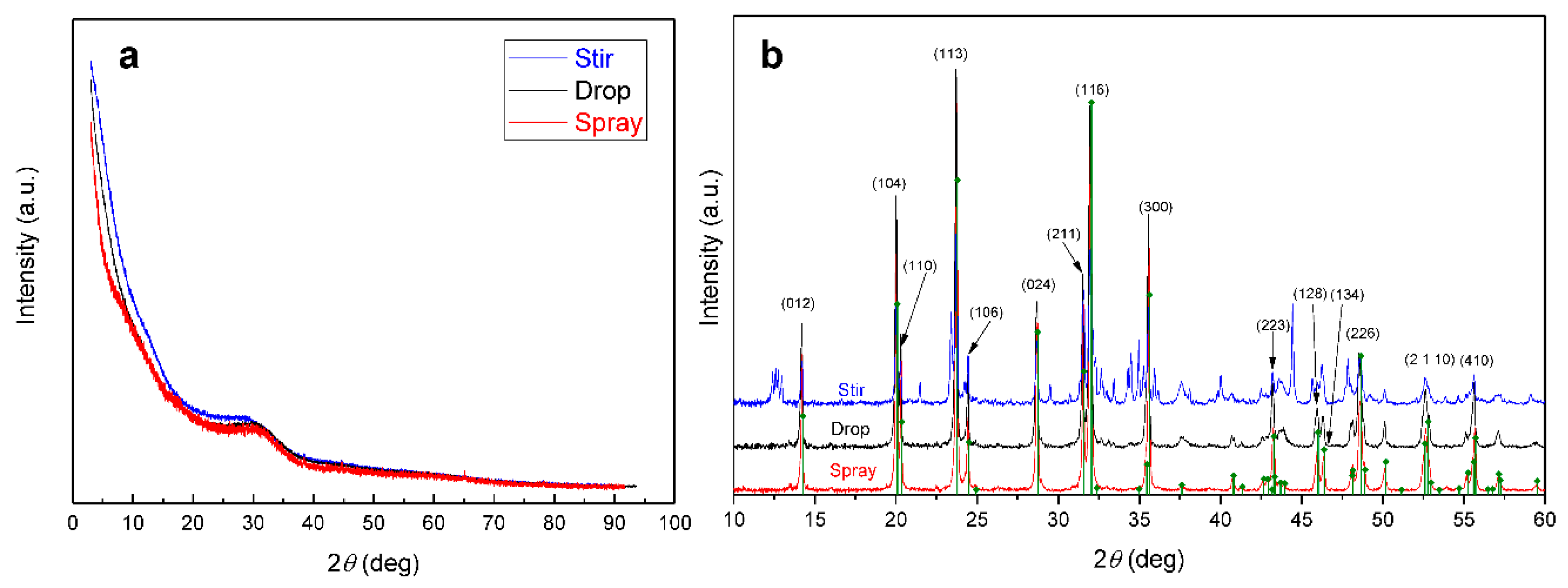
3.1. Physical Characterization of the Studied Materials

SEM image of the NVP-spray precursor (Figure 1a) reveals a holey morphology. Particles have varying sizes and shapes, but some plate-like structures with rough edges can be seen. The heat treated NVP-spray consists of much smaller particles (Figure 1b) with a varying size distribution. Particle size distribution can be narrowed by combining an ultrasonic spray method that ensures a constant flow of droplets with a similar size and an electrostatic or cyclone collector to separate different fractions. GDHC 1100 and 1400 in Figure 1c,d consist of smooth interconnected spherical particles with diameters around 400–500 nm. However, GDHC 1500 and 1600 in Figure 1e,f appear to be made of slightly larger interconnected and asymmetric particles. It can be concluded that heat-treatment temperatures (HTTs) above 1400 °C cause more pronounced structural changes to the primary particles formed during hydrothermal carbonization (HTC).
X-ray diffraction (XRD) data in Figure 2a indicates that the formed precursors are amorphous by nature because no sharp peaks can be observed. However, after heat treatment all samples contain the Na3V2(PO4)3 phase (Figure 2b). The NVP-drop and NVP-spray do not contain impurities and the intensities of the XRD peaks match the diffractogram from the database. NVP-stir has many unidentified peaks in the pattern, which are probably caused by the inhomogeneity of the viscous stir precursor during the last stages of heating. As water is evaporated from the mixture, the citric acid in the mixture turns the solution into an amorphous and sticky mass, which creates a temperature gradient in the mixture. This can result in heterogeneous distribution of elements in the mixture, which in turn leads to the formation of impurities during heat treatment. The droplets are much smaller and water evaporation is instantaneous with the drop and spray method, preventing temperature and concentration gradients from developing within the particles.

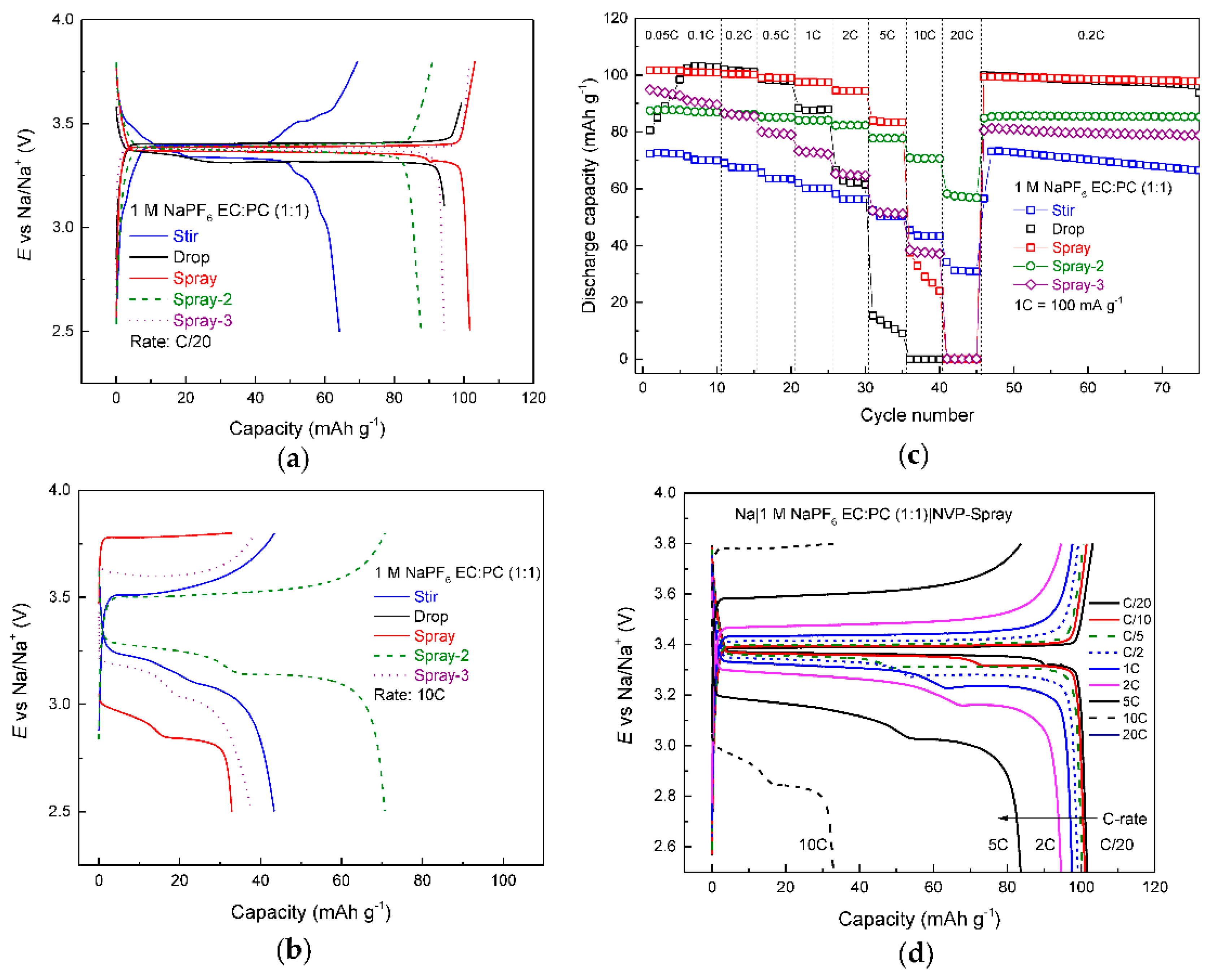
3.2. Electrochemical Characterization NVP Half Cells

Data in Figure 3a indicate that NVP-stir has a staging charge profile and a lower capacity (64 mAh g−1), which is in good agreement with XRD data. Multiple impurities that could not be identified are present and will therefore lower the gravimetric capacity of the material. All the other materials display very flat plateaus, some staging during discharge can be observed, explained by parasitic oxidation reactions on the surface of the sodium counter electrode [34]. NVP-spray displays the highest capacity—102 mAh g−1 at C/20—followed by NVP-drop and NVP-spray-3 (scaled up version of NVP-spray, but without added glucose) at 94 mAh g−1 and NVP-spray-2 at 88 mAh g−1. However, the order reverses at 10 C (Figure 3b), where NVP-spray-2 exhibits the best performance (70 mAh g−1) and NVP-drop the worst, reaching the cut-off voltage too early due to high IR-drop. The fact that NVP-spray-3 and NVP-spray-2 show high capacities at 10 C can be attributed to increased carbon content in the electrode material.
Firstly, 25 wt% of glucose was added to NVP-spray-2 precursor, which helps to form a carbon shell around the particles and therefore increases electronic conductivity of the material [31,35]. Secondly, some scaling effects seem to contribute to NVP-spray-3 having a higher capacity at 10 C than NVP-spray, even though no additional glucose was added to the precursor before the heat treatment step. This means that more organic material is left in the precursor matrix during precursor formation with larger quantities. Unfortunately, a sample containing a mixture of Na+, V3+ and PO43− ions is considered too aggressive for thermogravimetric analysis (TGA) for it can contaminate the thermocouple when Na+ diffuses through alumina, which is why TGA was not performed with these samples. Looking at the overall performance of all cells (Figure 3c), NVP-spray and NVP-drop showed superior performance at low rates (even after recovery from high-rate cycling (C/5)). NVP-spray demonstrates the highest capacities up to 5 C. Spray-2 shows the best high-power performance (60 mAh g−1) at 20 C. NVP-drop and NVP-stir are the only samples which show a faster fade at C/5 after high-rate cycling.
NVP-drop shows high capacity at low currents, but a rapid decline ensues as currents exceed 2 C. This can be explained by bigger crystal size that lengthens the path of diffusion for Na ions and the lack of a carbon shell around the particles that reduces electronic conductivity. NVP-spray is an improvement to NVP-drop by enabling higher C-rates and when scaled up (spray-2); it shows power characteristics that far exceed even NVP-stir, which initially seemed like the best candidate for a high-power cell. Figure 3d shows charge profiles of NVP-spray at various C-rates. It can be seen that after 2 C a drastic increase in ohmic drop is evident and capacity starts to decline. Interestingly, these stages are visible only in discharge profiles and become more pronounced as the applied current increases. As mentioned before, this can be due to parasitic reactions on the Na counter electrode [34], but has to be examined further as such phenomena have either not been observed in other works [31,36] or galvanostatic profiles have not been shown [37].

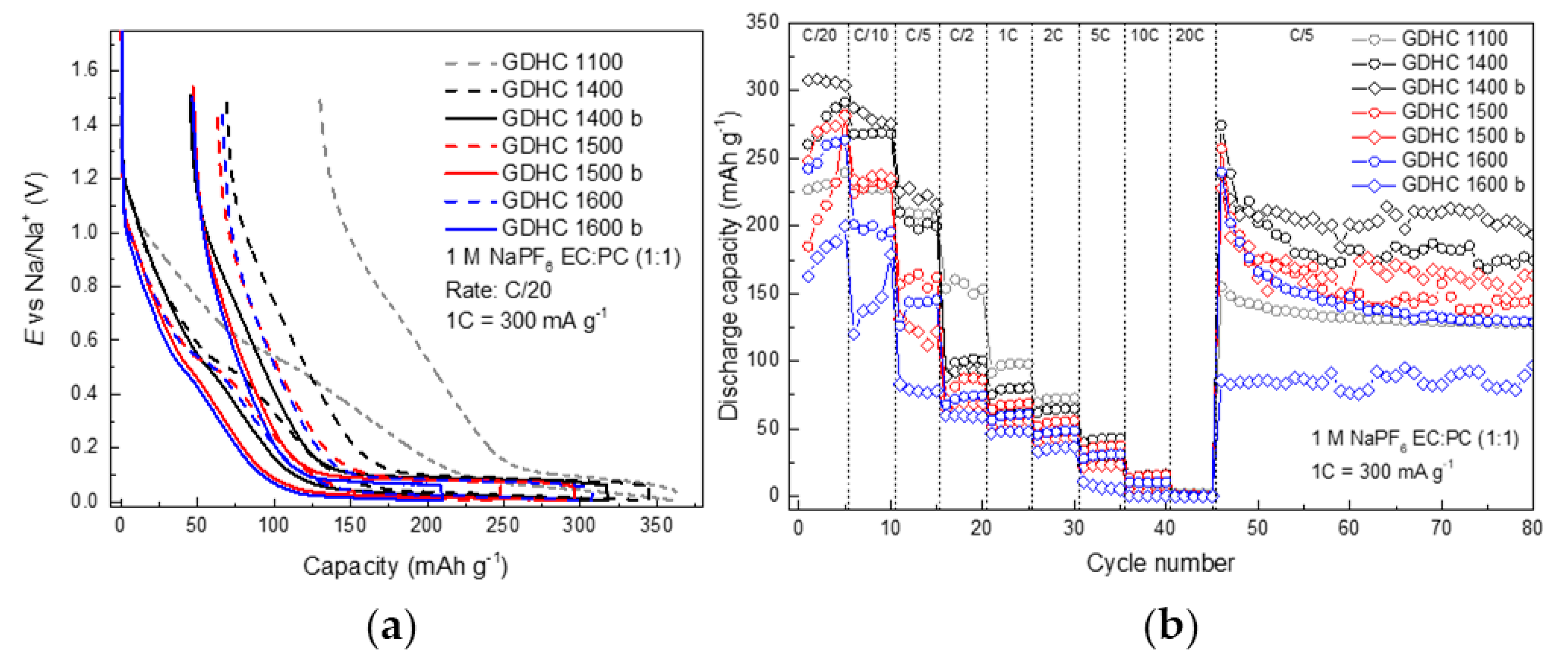
3.3. Electrochemical Characterization of Hard Carbon Half Cells

Our group has previously studied glucose-derived hard carbon (GDHC) that was heat treated at 1100 °C (GDHC 1100) [32,33,38,39], but it becomes clear from Figure 4a that such material is highly impractical in a full cell (Figure 5a). A high BET (Brunauer-Emmett-Teller) surface area of 238 m2 g−1 [32] means that a lot of charge carriers will be consumed in SEI (solid-electrolyte interphase) formation which in turn lowers reversible capacity and cell lifetime. In addition, one must remember that plateau capacity (E < 0.1 V) is what matters in a full cell.
Therefore, based on literature data [40], GDHCs were heat treated at higher temperatures (1400–1600 °C). The charge/discharge profiles in Figure 4a follow a logical order—with increasing temperature, both irreversible capacity and sloping area are reduced. However, plateau capacities also reduce which lowers 1st cycle coulombic efficiency (CE). By limiting the Super P in all electrodes, irreversible capacity is reduced from 66 mAh g−1 to 47 mAh g−1 and sloping region is reduced by 30 mAh g−1. Unfortunately, the plateau capacity is also reduced when Super P content is decreased from 15 wt % to 4 wt %. As shown in Figure 4b, the best overall performance is achieved with GDHC 1400 b (reduced Super P content). Higher plateau capacity, but similar irreversible capacity compared to higher temperatures yields a 1st cycle CE of 85%. Therefore, this carbon was chosen as the best candidate for full cell measurements.

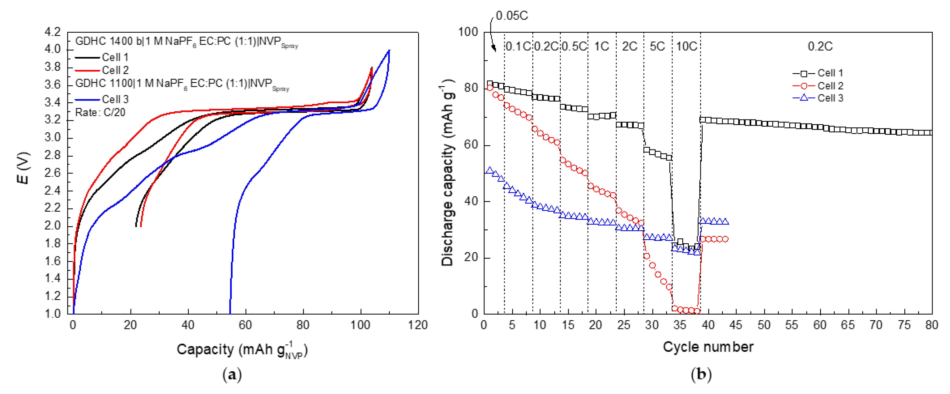
3.4. Electrochemical Characterization of GHDC||NVP Full Cells

Full cells were assembled using NVP-spray as the positive electrode and GDHC 1400 b or GDHC 1100 as the negative electrode to evaluate NVP-spray performance in a full cell. Figure 5a shows 1st charge/discharge profile for three cells with different QN/QP ratios, where QN is the negative electrode capacity and QP is the positive electrode capacity. Cell 1 has a QN/QP ratio of 1.1, which means the negative electrode is slightly oversized and therefore prevents Na plating on the hard carbon due to overcharge. This is common practice for commercial cells to increase safety [41,42]. Cell 2 QN/QP is 0.75, which means NVP is in large excess. Cell 3 with GDHC 1100 with QN/QP at 0.37 is shown for comparison to illustrate the effect high sloping region capacity has on full cell performance.
Data in Figure 5a show that although both cell 1 and 2 have a similar CE during the 1st cycle, the slight increase of cell potential at 90 mAh g−1 during charge is evidence that Na plating has taken place in cell 2. Figure 5b demonstrates the effect of misbalancing to overall cell performance: Cell 1 and 2 start from similar capacity values, but cell 2 declines rapidly, as plating of Na increases surface area and in turn leads to further electrolyte decomposition and loss of Na+. Cell 1 is very stable with CE of 99.7% at the 80th cycle.
Charge/discharge profiles in Figure 6 are comprised of two distinct regions and the shape of the profile is mainly determined by the hard carbon profile since NVP has a very flat plateau. As the plateau capacity of the hard carbon is depleted the full cell profile follows the sloping behavior of the hard carbon. Capacities for cell 1 reach 80 mAh g−1 and 60 mAh g−1 for the plateau region per NVP active mass. Calculated energy density for the full cell at C/20 was 104 Wh dm−3 and specific energy 189 Wh kg−1. Cell 1 rate performance (Figure 6) is similar to NVP-spray in Figure 3d—capacity decline after 2 C with increased ohmic drop—which in turn caused specific energy drop from 150 Wh kg−1 (at 2 C) to 119 Wh kg−1 (at 5 C) and energy density drop from 82 Wh dm−3 (at 2 C) to 65 Wh dm−3 (at 5 C). Interestingly, no stages can be observed in discharge profiles unlike in NVP half cells, which again supports the claim that reactions on Na electrode can distort the signal that is assumed to come from the working electrode [34].
Full cell results show how important it is to optimize the hard carbon electrode material towards a reduced surface area to reduce Na+ loss and the need for oversizing positive electrode mass loading to compensate for that loss. As we showed, care must be taken with other components such as the amount of conductive additive (Figure 5a), but also the binder, as Dahbi et al. demonstrated how CMC (carboxymethyl cellulose) enhances cell stability compared to PVDF [43].

4. Conclusions

This paper is a proof-of-concept study to demonstrate that NVP can be synthesized via the glycine-nitrate process (GNP). Various approaches were used to initiate the combustion reaction: stirring the mixture until it dried (stir), dropping the mixture on a hot Pt-crucible (drop) and spraying the mixture in the crucible (spray). NVP-spray showed the best high-energy performance—102 mAh g−1 at C/20. Scaling up the spray synthesis 12-fold (spray-2, spray-3) revealed some scaling effects, which led to improved high power performance with spray-2 reaching 60 mAh g−1 at 20 C.
Glucose-derived hard carbons (GDHC) were optimized to reduce irreversible capacity and sloping region in E vs. capacity plots. The best results were achieved with electrodes containing GDHC heat treated at 1400 °C and reduced Super P had the following characteristics: sloping region 90 mAh g1, irreversible capacity 47 mAh g−1, discharge capacity 272 mAh g−1 (of which plateau 155 mAh g−1) and 1st cycle coulombic efficiency (CE) 85%. GDHC||NVP full cell achieved reversible capacity 80 mAh g−1 by NVP mass (60 mAh g−1 at 3.3V; i.e., the plateau region) and a specific energy of 189 Wh kg−1 and energy density of 104 Wh dm−3. After 80 cycles, including rate testing from C/20 to 10 C, the cell cycled at 65 mAh g−1 with 99.7% CE. Once turned into a flow process, the GNP method has great industrial potential for cost-effective production of electrode material with finely tuned particle size distribution.

Author Contributions

Conceptualization: R.V.; methodology: R.V., M.H. and J.A.; writing—original draft: R.V., A.J. and E.L.; writing—review and editing: R.V., A.J. and E.L.; supervision: E.L.; resources: A.J.

Funding

This research was supported by the EU through the European Regional Development Fund (Center of Excellence TK141 2014-2020.4.01.15-0011 and higher education specialization stipends in smart specialization growth areas 2014-2020.4.02.16-0026, Graduate School of Functional Materials and Technologies in University of Tartu and NAMUR project 3.2.0304.12-0397). This work was partially supported by the Estonian Research Council Institutional Research Grant IUT20–13.

Acknowledgments

R. Väli thanks the Estonian Students Fund in the USA for their financial support. The authors thank G. Nurk, I. Kivi and O. Korjus for guidance at performing the GNP process.

Conflicts of Interest

The authors declare no conflicts of interest.

References

  1. British Geological Survey. Risk List 2015; British Geological Survey: Nottingham, UK, 2015.
  2. Carmichael, R.S. Practical Handbook of Physcial Properties of Rocks and Minerals; CRC Press: Boca Raton, FL, USA, 1989; ISBN 978-0-8493-3703-1. [Google Scholar]
  3. Hwang, J.-Y.; Myung, S.-T.; Sun, Y.-K. Sodium-ion batteries: Present and future. Chem. Soc. Rev. 2017, 46, 3529–3614. [Google Scholar] [CrossRef] [PubMed]
  4. Vaalma, C.; Buchholz, D.; Weil, M.; Passerini, S. A cost and resource analysis of sodium-ion batteries. Nat. Rev. Mater. 2018, 3, 18013. [Google Scholar] [CrossRef]
  5. Amnesty International. ‘This Is What We Die for.’ Human Rights Abuses in the Democratic Republic of the Congo Power the Global Trade in Cobalt; Amnesty International: London, UK, 2016. [Google Scholar]
  6. Yabuuchi, N.; Kubota, K.; Dahbi, M.; Komaba, S. Research Development on Sodium-Ion Batteries. Chem. Rev. 2014, 114, 11636–11682. [Google Scholar] [CrossRef] [PubMed]
  7. Hwang, J.; Matsumoto, K.; Hagiwara, R. Na3V2(PO4)3@Carbon Nanofibers: High Mass Loading Electrode Approaching Practical Sodium Secondary Batteries Utilizing Ionic Liquid Electrolytes. ACS Appl. Energy Mater. 2019, 2, 2818–2827. [Google Scholar] [CrossRef]
  8. Gopalakrishnan, J.; Rangan, K.K. V2(PO4)3: A Novel NASICON-Type Vanadium Phosphate Synthesized by Oxidative Deintercalation of Sodium from Na3V2(PO4)3. Chem. Mater. 1992, 4, 745–747. [Google Scholar] [CrossRef]
  9. Jian, Z.; Zhao, L.; Pan, H.; Hu, Y.-S.; Li, H.; Chen, W.; Chen, L. Carbon coated Na3V2(PO4)3 as novel electrode material for sodium ion batteries. Electrochem. Commun. 2012, 14, 86–89. [Google Scholar] [CrossRef]
  10. Chen, S.; Wu, C.; Shen, L.; Zhu, C.; Huang, Y.; Xi, K.; Maier, J.; Yu, Y. Challenges and Perspectives for NASICON-Type Electrode Materials for Advanced Sodium-Ion Batteries. Adv. Mater. 2017, 29, 1700431. [Google Scholar] [CrossRef]
  11. Cao, X.; Pan, A.; Yin, B.; Fang, G.; Wang, Y.; Kong, X.; Zhu, T.; Zhou, J.; Cao, G.; Liang, S. Nanoflake-constructed porous Na3V2(PO4)3/C hierarchical microspheres as a bicontinuous cathode for sodium-ion batteries applications. Nano Energy 2019, 60, 312–323. [Google Scholar] [CrossRef]
  12. Li, W.-J.; Han, C.; Wang, W.; Gebert, F.; Chou, S.-L.; Liu, H.-K.; Zhang, X.; Dou, S.-X. Commercial Prospects of Existing Cathode Materials for Sodium Ion Storage. Adv. Energy Mater. 2017, 7, 1700274. [Google Scholar] [CrossRef]
  13. Deganello, F.; Tyagi, A.K. Solution combustion synthesis, energy and environment: Best parameters for better materials. Prog. Cryst. Growth Charact. Mater. 2018, 64, 23–61. [Google Scholar] [CrossRef]
  14. Danks, A.E.; Hall, S.R.; Schnepp, Z. The evolution of ‘sol–gel’ chemistry as a technique for materials synthesis. Mater. Horiz. 2016, 3, 91–112. [Google Scholar] [CrossRef]
  15. Jain, S.R.; Adiga, K.C.; Pai Verneker, V.R. A new approach to thermochemical calculations of condensed fuel-oxidizer mixtures. Combust. Flame 1981, 40, 71–79. [Google Scholar] [CrossRef]
  16. Hajarpour, S.; Gheisari, K.; Raouf, A.H. Characterization of nanocrystalline Mg0.6Zn0.4Fe2O4 soft ferrites synthesized by glycine-nitrate combustion process. J. Magn. Magn. Mater. 2013, 329, 165–169. [Google Scholar] [CrossRef]
  17. Singh, S.; Singh, D. LaSrFeO4 nanopowders synthesized by different combustion methods: Effect of fuel/particle size. Ceram. Int. 2016, 42, 15725–15731. [Google Scholar] [CrossRef]
  18. Chick, L.A.; Pederson, L.R.; Maupin, G.D.; Bates, J.L.; Thomas, L.E.; Exarhos, G.J. Glycine-nitrate combustion synthesis of oxide ceramic powders. Mater. Lett. 1990, 10, 6–12. [Google Scholar] [CrossRef]
  19. Vujković, M.; Mitrić, M.; Mentus, S. High-rate intercalation capability of NaTi2(PO4)3/C composite in aqueous lithium and sodium nitrate solutions. J. Power Sources 2015, 288, 176–186. [Google Scholar] [CrossRef]
  20. Amaraweera, T.H.N.G.; Wijayasinghe, A.; Mellander, B.-E.; Dissanayake, M.A.K.L. Development of Li(Ni1/3Mn1/3Co1/3-xNax)O2 cathode materials by synthesizing with glycine nitrate combustion technique for Li-ion rechargeable batteries. Ionics 2017, 23, 3001–3011. [Google Scholar] [CrossRef]
  21. Habibi, A.; Jalaly, M.; Rahmanifard, R.; Ghorbanzadeh, M. Solution combustion synthesis of the nanocrystalline NCM oxide for lithium-ion battery uses. Mater. Res. Express 2018, 5, 025506. [Google Scholar] [CrossRef]
  22. Sloovere, D.D.; Marchal, W.; Ulu, F.; Vranken, T.; Verheijen, M.; Bael, M.K.V.; Hardy, A. Combustion synthesis as a low temperature route to Li4Ti5O12 based powders for lithium ion battery anodes. RSC Adv. 2017, 7, 18745–18754. [Google Scholar] [CrossRef]
  23. Doeff, M.M.; Richardson, T.J.; Hollingsworth, J.; Yuan, C.-W.; Gonzales, M. Synthesis and characterization of a copper-substituted manganese oxide with the Na0.44MnO2 structure. J. Power Sources 2002, 112, 294–297. [Google Scholar] [CrossRef]
  24. Eriksson, T.A.; Doeff, M.M. A study of layered lithium manganese oxide cathode materials. J. Power Sources 2003, 119, 145–149. [Google Scholar] [CrossRef]
  25. Doeff, M.M.; Richardson, T.J.; Hwang, K.-T. Electrochemical and structural characterization of titanium-substituted manganese oxides based on Na0.44MnO2. J. Power Sources 2004, 135, 240–248. [Google Scholar] [CrossRef]
  26. Saint, J.A.; Doeff, M.M.; Wilcox, J. Electrode Materials with the Na0.44MnO2 Structure: Effect of Titanium Substitution on Physical and Electrochemical Properties. Chem. Mater. 2008, 20, 3404–3411. [Google Scholar] [CrossRef]
  27. Ferrara, C.; Tealdi, C.; Dall’Asta, V.; Buchholz, D.; Chagas, L.G.; Quartarone, E.; Berbenni, V.; Passerini, S. High-Performance Na0.44MnO2 Slabs for Sodium-Ion Batteries Obtained through Urea-Based Solution Combustion Synthesis. Batteries 2018, 4, 8. [Google Scholar] [CrossRef]
  28. Zhang, R.; Yang, X.; Zhang, D.; Qiu, H.; Fu, Q.; Na, H.; Guo, Z.; Du, F.; Chen, G.; Wei, Y. Water soluble styrene butadiene rubber and sodium carboxyl methyl cellulose binder for ZnFe2O4 anode electrodes in lithium ion batteries. J. Power Sources 2015, 285, 227–234. [Google Scholar] [CrossRef]
  29. Adams, R.A.; Pol, V.G.; Varma, A. Tailored Solution Combustion Synthesis of High Performance ZnCo2O4 Anode Materials for Lithium-Ion Batteries. Ind. Eng. Chem. Res. 2017, 56, 7173–7183. [Google Scholar] [CrossRef]
  30. Yang, L.; Wang, M.; Zeng, D. Precursor Formulation for Battery Active Materials Synthesis. US Patent US13/470,041, 11 May 2012. [Google Scholar]
  31. Wang, H.; Jiang, D.; Zhang, Y.; Li, G.; Lan, X.; Zhong, H.; Zhang, Z.; Jiang, Y. Self-combustion synthesis of Na3V2(PO4)3 nanoparticles coated with carbon shell as cathode materials for sodium-ion batteries. Electrochim. Acta 2015, 155, 23–28. [Google Scholar] [CrossRef]
  32. Väli, R.; Jänes, A.; Thomberg, T.; Lust, E. D-Glucose Derived Nanospheric Hard Carbon Electrodes for Room-Temperature Sodium-Ion Batteries. J. Electrochem. Soc. 2016, 163, A1619–A1626. [Google Scholar] [CrossRef]
  33. Väli, R.; Jänes, A.; Thomberg, T.; Lust, E. Synthesis and characterization of d-glucose derived nanospheric hard carbon negative electrodes for lithium- and sodium-ion batteries. Electrochim. Acta 2017, 253, 536–544. [Google Scholar] [CrossRef]
  34. Lee, S.E.; Tang, M.H. Electroactive decomposition products cause erroneous intercalation signals in sodium-ion batteries. Electrochem. Commun. 2019, 100, 70–73. [Google Scholar] [CrossRef]
  35. Guo, B.; Diao, W.; Yuan, T.; Liu, Y.; Yuan, Q.; Li, G.; Yang, J. Enhanced electrochemical performance of Na3V2(PO4)2F3 for Na-ion batteries with nanostructure and carbon coating. J. Mater. Sci. Mater. Electron. 2018, 29, 16325–16329. [Google Scholar] [CrossRef]
  36. Lim, S.Y.; Kim, H.; Shakoor, R.A.; Jung, Y.; Choi, J.W. Electrochemical and Thermal Properties of NASICON Structured Na3V2(PO4)3 as a Sodium Rechargeable Battery Cathode: A Combined Experimental and Theoretical Study. J. Electrochem. Soc. 2012, 159, A1393–A1397. [Google Scholar] [CrossRef]
  37. Klee, R.; Aragón, M.J.; Alcántara, R.; Tirado, J.L.; Lavela, P. High-Performance Na3V2(PO4)3/C Cathode for Sodium-Ion Batteries Prepared by a Ball-Milling-Assisted Method. Eur. J. Inorg. Chem. 2016, 2016, 3212–3218. [Google Scholar] [CrossRef]
  38. Väli, R.; Jänes, A.; Lust, E. Alkali-Metal Insertion Processes on Nanospheric Hard Carbon Electrodes: An Electrochemical Impedance Spectroscopy Study. J. Electrochem. Soc. 2017, 164, E3429–E3437. [Google Scholar] [CrossRef]
  39. Mathiesen, J.K.; Väli, R.; Härmas, M.; Lust, E.; Bulow, J.F.V.; Jensen, K.M.Ø.; Norby, P. Following the In-plane Disorder of Sodiated Hard Carbon through Operando Total Scattering. J. Mater. Chem. A 2019, 7, 11709–11717. [Google Scholar] [CrossRef]
  40. Dou, X.; Hasa, I.; Saurel, D.; Vaalma, C.; Wu, L.; Buchholz, D.; Bresser, D.; Komaba, S.; Passerini, S. Hard carbons for sodium-ion batteries: Structure, analysis, sustainability, and electrochemistry. Mater. Today 2019, 23, 87–104. [Google Scholar] [CrossRef]
  41. Meister, P.; Jia, H.; Li, J.; Kloepsch, R.; Winter, M.; Placke, T. Best Practice: Performance and Cost Evaluation of Lithium Ion Battery Active Materials with Special Emphasis on Energy Efficiency. Chem. Mater. 2016, 28, 7203–7217. [Google Scholar] [CrossRef]
  42. Kasnatscheew, J.; Placke, T.; Streipert, B.; Rothermel, S.; Wagner, R.; Meister, P.; Laskovic, I.C.; Winter, M. A Tutorial into Practical Capacity and Mass Balancing of Lithium Ion Batteries. J. Electrochem. Soc. 2017, 164, A2479–A2486. [Google Scholar] [CrossRef]
  43. Dahbi, M.; Nakano, T.; Yabuuchi, N.; Ishikawa, T.; Kubota, K.; Fukunishi, M.; Shibahara, S.; Son, J.-Y.; Cui, Y.-T.; Oji, H.; et al. Sodium carboxymethyl cellulose as a potential binder for hard-carbon negative electrodes in sodium-ion batteries. Electrochem. Commun. 2014, 44, 66–69. [Google Scholar] [CrossRef]
Scheme 1. Schematic representation of the synthesis steps with sample notation.
Batteries 05 00056 sch001
Figure 1. SEM images of (a) NVP-spray precursor, (b) NVP-spray final product and (cf) glucose-derived hard carbons (GDHCs). The numbers after GDHC indicates heat treatment temperature in °C.
Batteries 05 00056 g001
Figure 2. XRD patterns of (a) the three precursors and (b) final products with NVP pattern from the database.
Batteries 05 00056 g002
Figure 3. Galvanostatic charge/discharge data for NVP half cells. Profiles for NVP half cells (noted in figure) at (a) C/20, (b) 10 C, (c) discharge capacities for the tested NVP half cells and (d) profiles for NVP-spray half cell at various C-rates (noted in figure).
Batteries 05 00056 g003
Figure 4. Galvanostatic charge/discharge data for GDHC half cells. Profiles of (a) the first charge/discharge cycle of GDHC half cells synthesized at various temperatures and with varying Super P content: 15 wt % (dashed line) or 4 wt% (solid line, noted with ‘b’) and (b) discharge capacities of GDHC half cells.
Batteries 05 00056 g004
Figure 5. Galvanostatic charge/discharge data for GDHC full cells; (a) profiles of the first charge/discharge cycle for GDHC||NVP full cells and (b) discharge capacities for full cells at various cycling rates (noted in figure).
Batteries 05 00056 g005
Figure 6. Galvanostatic charge/discharge profiles for cell 1 at various C-rates (noted in figure).
Batteries 05 00056 g006
Table 1. Molar ratios of substrates (in relation to V), added glucose to the precursor and heat treatment yields (HT) of the synthesized materials. Explanations of abbreviations given in text.
SamplemNH4VO3 (g)Na:VP:VCA:VG:VFuels:VGlucose (wt%)HT Yield (%)
NVP-stir0.5131.51.53.7303.73092
NVP-drop0.5141.51.53.7303.75036
NVP-spray0.5131.51.51.151.052.202570
NVP-spray-26.4421.51.51.151.052.192571
NVP-spray-36.6691.51.51.151.052.20088
NVP—sodium vanadium phosphate or Na3V2(PO4)3, Na—sodium, V—vanadium, P—phosphorus, CA—citric acid, G—glycine, Fuels—citric acid and glycine, HT—heat treatment.

