Article

Mechanism of Ionic Impedance Growth for Palladium-Containing CNT Electrodes in Lithium-Oxygen Battery Electrodes and Its Contribution to Battery Failure

1
Department of Mechanical and Materials Engineering, Florida International University, Miami, FL 33174, USA
2
Department of Mechanical and Industrial Engineering, The University of Illinois at Chicago, Chicago, IL 60607, USA
*
Author to whom correspondence should be addressed.
Batteries 2019, 5(1), 15; https://doi.org/10.3390/batteries5010015
Submission received: 30 November 2018 / Revised: 7 January 2019 / Accepted: 22 January 2019 / Published: 23 January 2019
(This article belongs to the Special Issue Recent Advances in Post-Lithium Ion Batteries)

Abstract

:
The electrochemical oxygen evolution reaction (OER) and oxygen reduction reaction (ORR) and on CNT (carbon nanotube) cathode with a palladium catalyst, palladium-coated CNT (PC-CNT), and palladium-filled CNT (PF-CNT) are assessed in an ether-based electrolyte solution in order to fabricate a lithium-oxygen battery with high specific energy. The electrochemical properties of the CNT cathodes were studied using electrochemical impedance spectroscopy (EIS). Palladium-filled cathodes displayed better performance as compared to the palladium-coated ones due to the shielding of the catalysts. The mechanism of the improvement was associated to the reduction of the rate of resistances growth in the batteries, especially the ionic resistances in the electrolyte and electrodes. The scanning electron microscopy (SEM) and spectroscopy were used to analyze the products of the reaction that were adsorbed on the electrode surface of the battery, which was fabricated using palladium-coated and palladium-filled CNTs as cathodes and an ether-based electrolyte.

1. Introduction

Rechargeable batteries convert chemical energy to electrical energy by the reversible electrochemical reactions of reduction and oxidation. Various types of secondary battery systems that have been studied, developed, and used in the past, include nickel-metal hydride, lead-acid, lithium-ion batteries, and redox-flow batteries [1,2,3,4]. Owning to their high specific energy, lithium-ion batteries have found applications in various fields. Due to the growing demand for advanced energy storage solutions for the smart grids, automotive industries, and other consumer applications, the research for ultra-high theoretical specific energy has led to studies beyond lithium-ion batteries, where metal-air batteries have been at the forefront of this research [5,6,7]. Metal-air batteries are unique because the cathode material, i.e., oxygen gas, can be obtained from the atmosphere, instead of storing it in the battery. Lithium–air batteries have a high theoretical specific energy density of 3500 Wh.kg−1 (considering the cathode), which is many folds higher than current lithium-ion batteries [8,9].
Abraham et al. first reported on a non-aqueous lithium-oxygen battery in 1996, which consisted of a lithium anode, a polymer electrolyte, and a porous carbon-air cathode [9]. Since then, several studies have been conducted to study the rechargeability of Li-O2 batteries. During the discharging of a Li-O2 battery, Li+ migrates through the electrolyte to the cathode, where the incoming electrons from the external circuit combine with oxygen from the atmosphere to form peroxide ions, O22, which, in turn, reacts with the Li+ in an oxygen reduction reaction (ORR) to form the discharge product, Li2O2. During charging, a reverse reaction, as well as an oxygen evolution reaction (OER) occurs, regenerating the Li+ and O2. The reaction is represented as follows:
2Li+ + O2 + 2e ↔ Li2O2.
Many carbonaceous materials have been used as cathodes for Li-O2 batteries [10]. Some of the cathode materials used have been carbon nanoparticles [11,12], carbon nanofibers [13,14], carbon nanotubes [10,12,13,15,16,17], graphene platelets [18,19], and other forms of carbons [20,21]. Carbon nanotubes (CNTs) are known to have high electrical conductivity, a high specific area, more numbers of accessible active sites for reactions, and better chemical stability. All these properties make them a suitable choice for use as Li-O2 battery cathodes [10,17,22,23,24].
Several metal and metal-oxide catalysts have been used in and as cathodes of Li-O2 batteries in order to improve the catalytic properties of the OER and ORR [25,26,27,28,29]. Some of the elements used have been platinum [30], palladium [31], ruthenium [26,27,32,33,34,35], gold [30,36], and various metal oxides [37,38,39]. The presence of a catalyst destabilizes the oxidizing species, which results in decreased charging overpotential in Li-O2 batteries [40,41,42]. It also improves the cyclability [24,25,26,27,40], and thus the overall battery performance. Gittleson et al. [43,44] have shown that palladium and platinum catalysts promote Li2O2 oxidation at lower potentials. However, they also reported the occurrence of electrolyte decomposition that resulted in the formation of lithium carbonates, which deactivated the catalysts. The porous carbon cathode was passivated by a protective Al2O3 layer, applied using atomic layer deposition by Khalil et al. [21] prior to coating Pd catalysts. Their approach led to the formation of a nanocrystalline Li2O2 during discharge that helped improve the electronic transport properties, thus reducing the charge over-potential to about 0.2 V [21]. According to Li et al., Ru nanocrystals, when used as catalysts, decomposed Li2CO3 at 3.5 V, thus reducing the accumulation of Li2CO3 in in the cathode during cycling.
In order to overcome the agglomeration of catalysts and deactivation of Li-O2 batteries, dispersing catalysts were dispersed in polymeric membranes over the oxygen electrode, and an atomic layer deposition was used to chemically bind the catalysts to the surface of carbon nanotubes, where the CNTs were then filled with catalysts [10,35,45,46,47,48]. In our previous work, we filled the CNT annulus with palladium nanocatalysts and reported increased stability of the electrolyte during the charge and discharge process [10]. In addition, the full discharge of the battery to 2 V resulted in a six-fold increase in the first discharge capacity compared to the pristine CNT cathodes, and over 35% for their PC-cathodes.
In this paper, we investigate and report the electrochemical impedance performance of PC-and PF-CNT cathodes during charge/discharge cycling to unveil the failure mechanism of the batteries. We also investigate the chemical nature and morphology of deposits on the electrodes using FTIR (Fourier Transform Infrared Spectroscopy) and scanning electron microscopy (SEM) to corroborate the results from the electrochemical impedance spectroscopy (EIS) study.

2. Experimental

Materials: Bis (trifluoromethane) sulfonamide with a purity of >99.8% (LiTFSI), tetraethylene glycol dimethyl ether of >99.00% purity (TEGDME), N-Methyl pyrrolidine of >97% purity, and multi-walled carbon nanotubes (MWCNTs) with a diameter of 5–20 nm, length of 5 µm, and purity >96% of carbon basis were purchased from Sigma Aldrich. Palladium (II) chloride was purchased from ACROS organics. PVDF (Polyvinylidene fluoride) was procured from Alfa Aesar. Fuel Cell Earth supplied the carbon cloth gas diffusion layer (CCGDL) with a thickness of ∼300 µm. Lithium chips with a purity >99.90% and a Celgard polypropylene separator with a thickness of ∼25 µm were bought from MTI Corp. Scheme 1 depicts the assembly of the batteries.
Preparation of the Electrode: We have followed the procedure for PF-CNTs preparation as described in our previous paper [10,49]. Briefly, nitric acid treatment was performed on the MWCNTs to decap the ends. 100 mg of decapped multi-walled carbon nanotubes (MWCNTs) was blended with 1 mM aqueous solution of PdCl2 until a slurry was formed. A similar procedure was followed on the untreated capped MWCNTs to obtain PC-CNTs. Both slurries were preserved at 25 °C for 10 h and then calcinated in air at 350 °C for ~2 h. Calcination was followed by hydrogenation that resulted in a yield of ∼5 wt.% palladium nanoparticles. Preparation of cathode was as mentioned in the preceding paper [10]. Slurry of PVDF/PF and PC-CNT (10/90 wt.% in N-Methyl-2-pyrrolidone or NMP) was used to coat the cathodes on carbon cloth with a 0.5” diameter. The cathodes were dried for 12 hours at 120 °C and then stocked in an argon-filled glovebox. The loading of MWCNT was 0.39 ± 0.01 mg.cm−2. All the capacities reported in this manuscript are per total mass of active cathode including the catalyst and CNTs.
Electrolyte Preparation and Battery Test Assembly: 1 M LiTFSI in TEGDME solution was used to prepare the electrolyte. Modified Swagelok-type cells were used for our battery assemblies. It consisted of a stainless-steel tube on the cathode side and a stainless-steel rod on the anode side. Celgard 2400 separator which was soaked with the electrolyte was arranged on the lithium metal disc anode. Then, the MWCNT-CCGDL was placed on it, followed by a stainless-steel mesh current collector. The batteries were then placed inside an Ar-filled glove box (<1 ppm O2 and <0.1 ppm H2O) for resting overnight before the electrochemical tests.
Electrochemical Characterizations: Before testing the batteries, they were rested under oxygen for 5 h. Galvanostatic discharge/charge tests were performed on the Gamry 600TM Reference electrochemical workstation. Charge/discharge tests were performed within 2.0–4.5 V voltage range at a 250 mA·g−1 current density. The electrochemical characteristics of the cell were investigated by Electrochemical Impedance Spectroscopy (EIS) performed using a Gamry 600TM electrochemical workstation. Impedance data was collected in the frequency range of 106–0.01 Hz. The environment was temperature-controlled at 25 °C for all charge/discharge and electrochemical tests. After cycling, the oxygen cathodes were recovered, rinsed with dimethyl carbonate (DMC), and dried under vacuum inside the Ar-filled glove box.
Infrared Characterizations: The cathodes were investigated by FTIR (Fourier transform infrared) spectroscopy using JASCO FT-IR 4100 (company, city, country) for product characterization in the 500–4000 cm−1, mid-IR frequency region. A resolution of 4 cm−1 was used for each spectrum. For pretreatment for FTIR, the samples were rinsed three times with DMC (dimethyl carbonate) to remove the electrolyte salt from the cathode surface, and dried in vacuum to volatize the DMC.

3. Results and Discussion

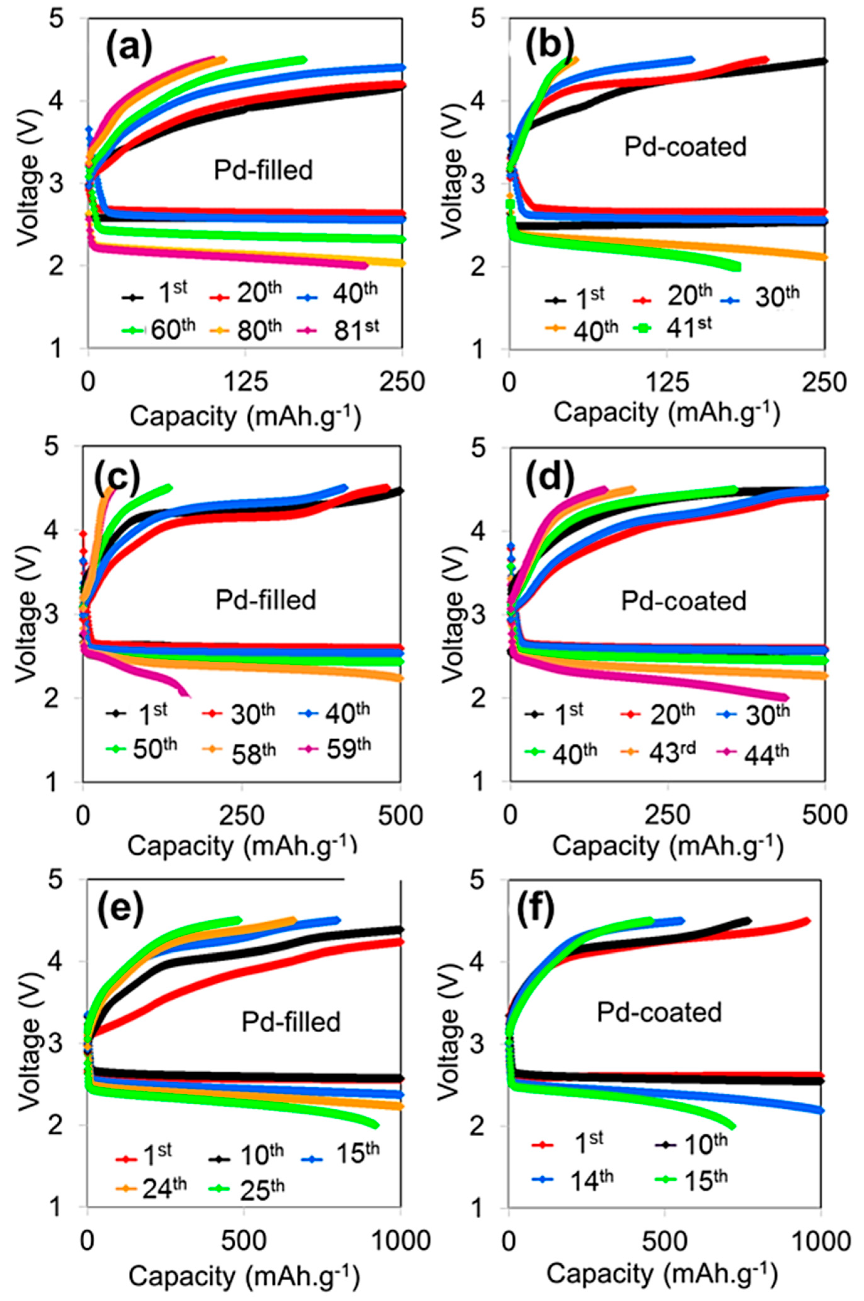
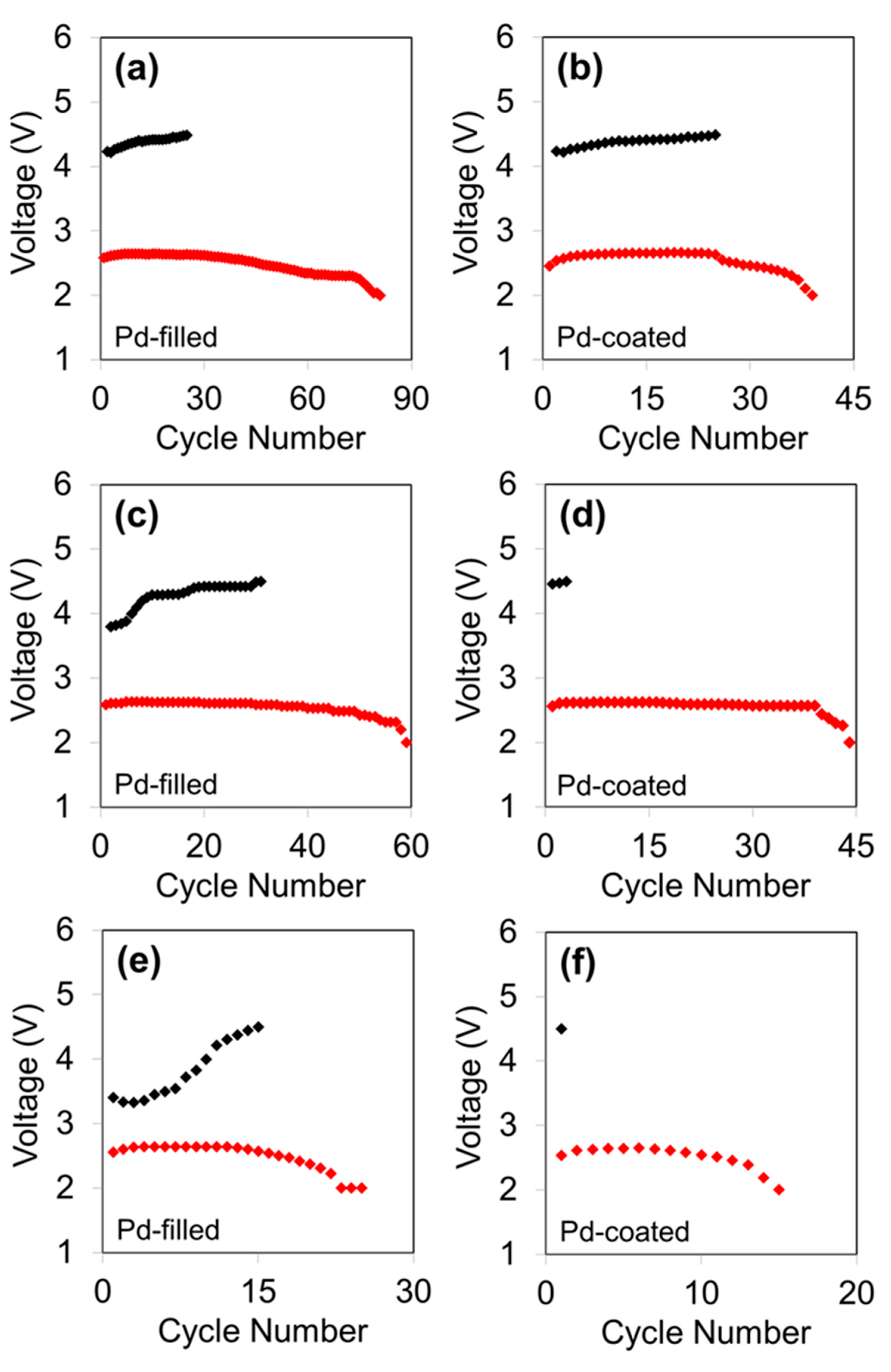
Li-O2 batteries with cathodes comprising PC and PF-CNTs showed full discharge capacities of ~8200 mAh.g−1 and ~11,200 mAh.g−1, respectively [10]. The batteries were discharged to 2 V under oxygen. Galvanostatic cycling was employed to characterize the electrochemical properties on the cathodes during the OER and ORR processes. Cycle performance of the Li-O2 batteries with PC-and PF-CNTs as cathodes were investigated at fixed capacities of 250 mAh.g−1, 500 mAh.g−1, and 1000 mAh.g−1 at a 250 mA.g−1 current density between 2.0–4.5 V (Figure 1). At 250 mAh.g−1, 41 and 81 cycles were obtained using PC-and PF-CNTs, respectively. At 500 mAh.g−1, 44 and 58 cycles were obtained using PC-and PF-CNTs, respectively. 16 and 25 cycles were obtained at 1000 mAh.g−1. Figure 2 shows the terminal discharge voltages of the batteries.
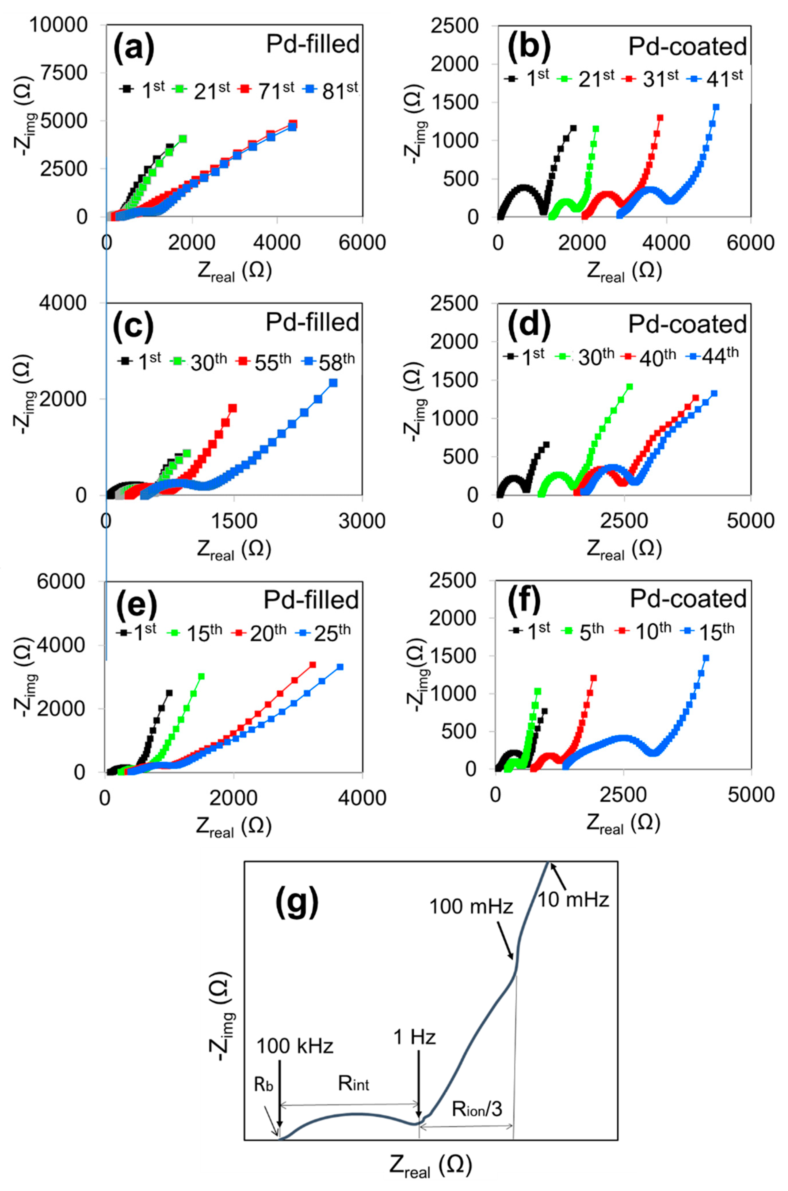
EIS measurements were performed after discharge/charge cycles to investigate the cathode/electrolyte behavior during discharging and charging processes. The Nyquist plot after discharge shows a high-frequency intercept, Rb, which correlates to the resistance of cell, including contributions from the electrolyte, electrodes, and contact resistances [16,50,51,52,53,54,55,56], as shown in Figure 3g. Rb is the high-frequency intercept and is obtained from the real EIS spectra. The EIS spectrum is followed by the semicircle that is associated with charge-transfer resistance at the cathode/O2/electrolyte interface [50,51,52], represented by Rint (interfacial resistance). Rint is obtained from the diameter of the semicircle of EIS. This is generally attributed to the Li2O2 which forms on the surface of the cathode after discharge, which hinders charge transfer and O2 diffusion through the pores of the cathode [51]. Following Rint there is a linear rise which is known as the Warburg-like linear region, which has also been reported in other metal-O2 battery EIS spectra at non-Faradaic conditions. In order to determine the impedance behavior of the porous electrodes in lithium-ion and metal−O2 batteries, the TLM or transmission line model was used. It is assumed that the Warburg-like linear region corresponds to the resistance of lithium-ion migration at the cathode, and is represented as Rion. We used a TLM model and estimated the Rion by the projection of the Warburg-like line on the impedance abscissa (Rion/3), as shown in Figure 3b [16,54].
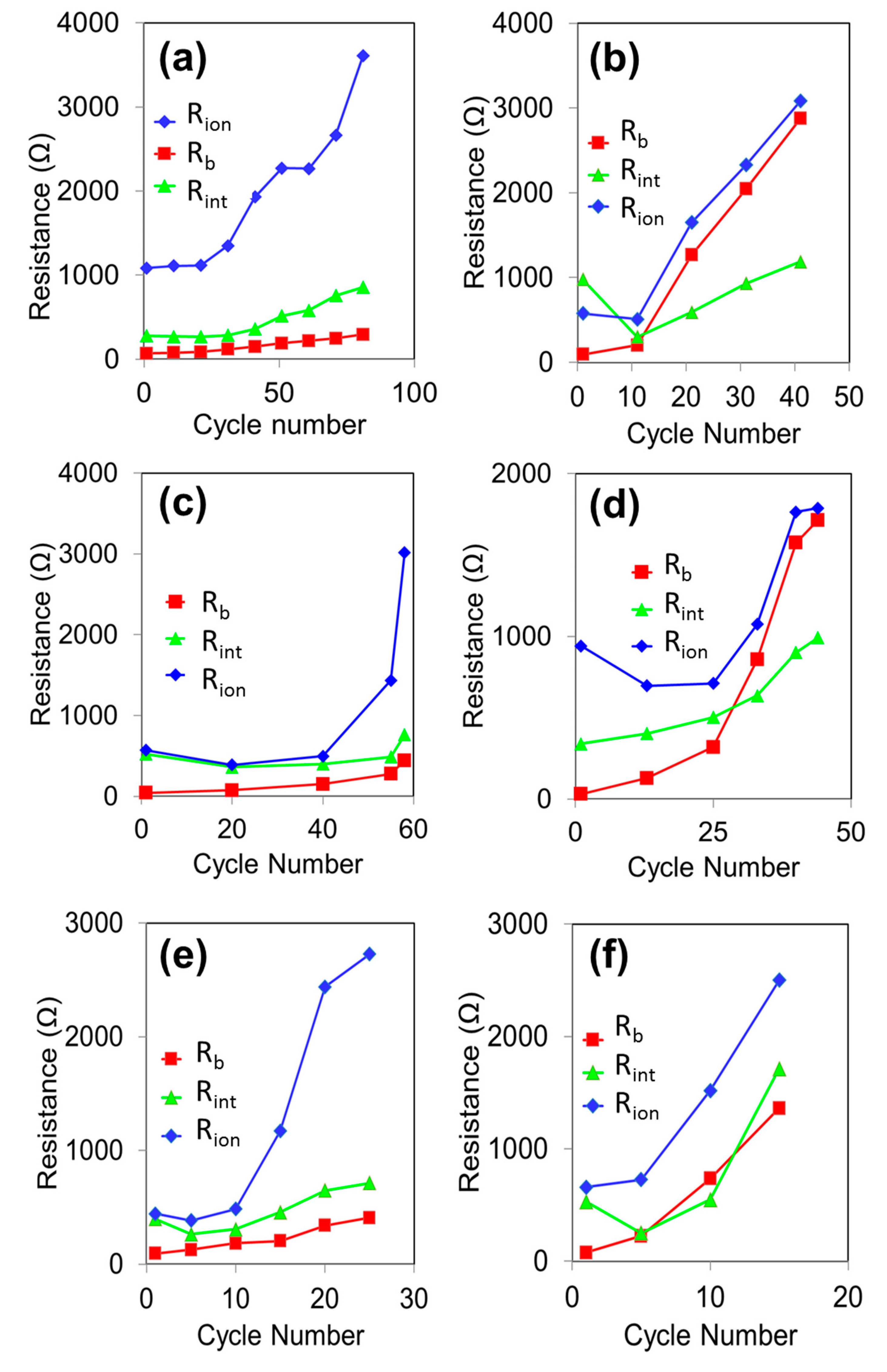
In Figure 3, the Nyquist plot exhibits a semicircle with a smaller diameter for PF-CNT, and a semicircle with a bigger diameter for the PC-CNTs after the first discharge to 250 mAh.g−1. The semicircle diameter corresponds to the charge-transfer resistance [51]. Higher charge-transfer resistance leads to slower charge-transfer kinetics [51]. From Figure 4, it is evident that the PC-cathode has slower charge-transfer kinetics as compared to PF-CNTs, due to higher resistance. As the number of cycles increase, we can see a shift of the high-frequency intercept, Rb, toward the right. From Figure 3a,b and Figure 4a,b, the shift is clearly visible for both cathodes. Figure 4 shows the change in the resistances after discharging the batteries to 250 mAh.g−1(a,b), 500 mAh.g−1(c,d), and 1000 mAh.g−1 (e,f). After the last discharging cycle up to 250 mAh.g−1, which is 41 cycles for PC-CNT and 81 cycles of PF-CNT, respectively, Rb has shifted from 80 Ω to 2910 Ω for PC-CNT, whereas the shift of Rb for PF-CNT is from 80 Ω to 300 Ω (Figure 4a,b). This shift in Rb is attributed to electrolyte decomposition and formation of lithium carbonates over time. In Figure 4c, for PF-CNT discharged up to 500 mAh.g−1, the Rb increases from 70 Ω for the first cycle, to 300 Ω for the last cycle. For PC-CNT (Figure 4d), the Rb increases from 90 Ω to 1700 Ω. In Figure 4e, for PF-CNT discharged up to 1000 mAh.g−1, the Rb increases from 70 Ω for the first cycle to 250 Ω for the 25th cycle. However, in the case of PC-CNT (Figure 4f), the Rb increases from 80 Ω to 1200 Ω. The gradual increase in the value of Rb is credited to the slow accumulation of the reaction products, Li2O2 and Li2O, within the pores of the carbon electrode, whereas the steep increase is an indication of a complete blockage of the carbon electrode that prevents further reduction of O2 [56]. This shift in Rb is attributed to electrolyte decomposition and formation of lithium carbonate (Li2CO3) over time [51]. As seen in Figure 4, Rint decreases minimally for the first 30 cycles of PF-CNTs and then increases. For PC-CNTs, Rint decreases for the first 10 cycles after the first discharge and then keeps increasing. Rion was the major resistance in both cathodes, and it keeps increasing with the number of cycles, as seen in the figure. Anode/electrolyte interface initially governs the interfacial resistance of Li-O2 batteries [24,57]. The initial decrease in the value of Rint is mainly attributed to the dissolution of the passivation film on the anode/electrolyte film’s interface [16]. Accumulation of irreversible discharge/charge by-products on the anode/electrolyte [16] and cathode/electrolyte interfaces [16,57] results in an increased Rint value during later cycles. Yi et al. [58,59] showed that an increased interfacial resistance on the cathode/electrolyte interface in Li-O2 batteries could be the result of lithium carbonate by-product formation during cycling. According to Shui et al. [60], deactivation of the cathode leads to Li-O2 battery death. Increase in Rion during cycling is an indication that the cathode pores have been clogged, meaning that Li+ ion transport is hindered [16].
For the cycles of 1000 mAh.g−1 as the fixed capacity, similar Nyquist plots were observed (Figure 4c,d). In this case too, the PF-CNT was cycled for 25 cycles, as compared to 16 cycles with PC-CNTs. After the last discharging cycle of up to 1000 mAh.g−1, Rb shifted from 80 to 1350 for PC-CNT, whereas the shift for PF-CNT was from 80 to 400. This indicates more electrolyte decomposition in the case of PC-CNTs. Rion had the highest resistance for both cases. Hence, in this case too, the battery failure was primarily due to pore-clogging.
As shown by the EIS, the formation of Li2O2 hinders the charge transfer between the interfaces and the decomposition of electrolyte [16]. Both reasons lead to the failure of Li-O2 batteries. To investigate the composition of the deposits that clog the pores of the cathodes, we performed FTIR on PC and PF-CNT cathodes after cycling for 15 and 45 cycles at fixed capacities of 1000 mAh.g−1 and 250 mAh.g−1. The peak at around 590 cm−1 is attributed to Li2O2, and Li2CO3 produces a peak at 862 cm−1 [61]. From Figure 5, it can be observed that the peaks of Li2CO3 are higher in the case of PC, rather than PF-CNTs. Better cycling was observed in PF-CNTs due to less undesirable products. The improvement in the cycling stability of PF-CNTs over the PC-CNTs was a result of the decrease in undesirable charge/discharge product formation, e.g., Li2CO3, caused by the encapsulation approach [10].
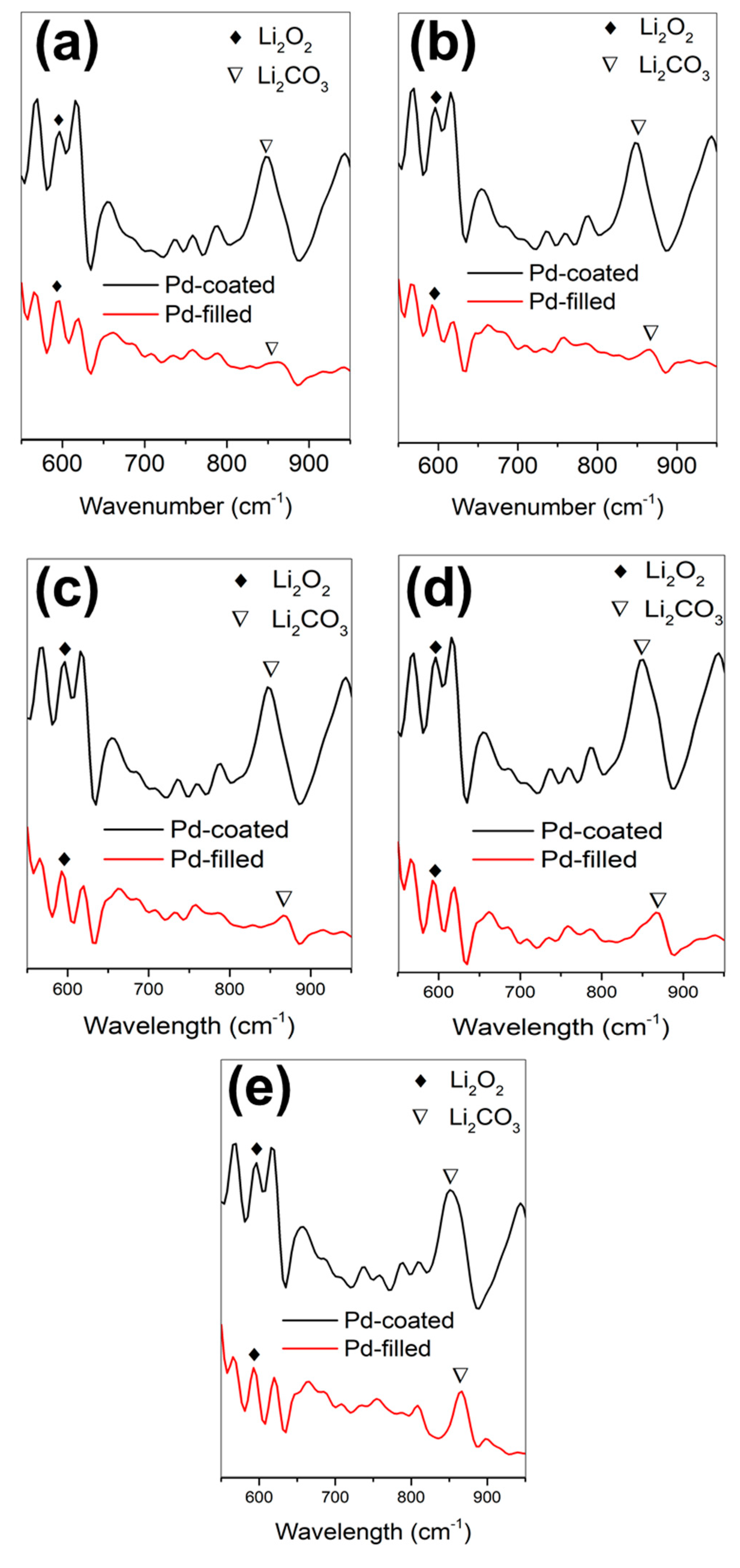
Figure 6 shows a comparison between PC-and PF-CNTs at capacities of 500, 1000, 1500, 5000, and 8000 mAh.g−1. As observed from the figure, at 500 mAh.g−1, a Li2O2 peak is present in both cathodes. A distinct Li2CO3 peak is observed for PC-CNT but is negligible in the case of PF-CNT. At all the capacities, Li2O2 peaks are present for both PC-and PF-CNT cathodes. However, the Li2CO3 peak for PF-CNT cathodes gradually increases as the capacity increases. Low Li2CO3 formation in the PF-CNT, as compared to PC-CNT results in increased battery performance [61].
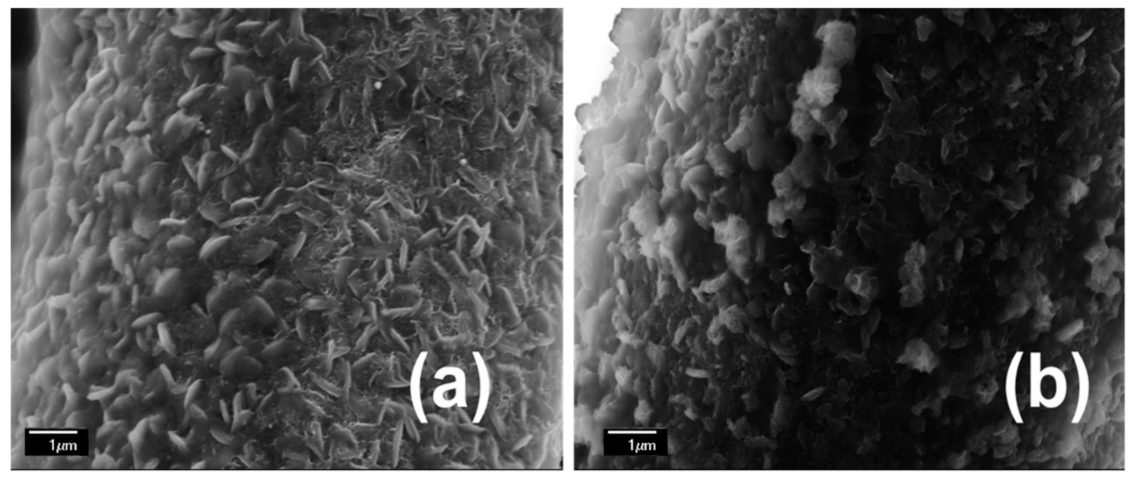
SEM proved the formation of Li2CO3 dendrites on the cathode surface after cycling, as shown in Figure 7. When the batteries were cycled between 2.0 and 4.0 V, there is a constant accumulation of lithium carbonate (Li2CO3) arising from the reactions involving the electrode and electrolyte [62], which results in electrode passivation and capacity fading in cells with carbon electrodes. Lithium carbonates are also produced as a result of the side-reaction of lithium peroxide with moisture and carbon dioxide from the atmosphere. It is difficult to be decomposed, and considerably deteriorated the cycling life [20,63]. The large over-charge potential can induce the side-reaction of oxidation decomposition of the electrode and electrolyte during Li2O2 oxidation, which results in the formation of Li2CO3 [62]. The accumulation of Li2CO3 in the electrode led to electrode passivation and capacity-fading on cycling. The PC-CNT cathode shown in Figure 7b presents platelet-shaped lithium peroxide (Li2O2) covered by a thick conformal layer of lithium carbonates (Li2CO3), as shown in the FTIR measurements whereas the PF-CNTs showed nano-thin platelets of Li2O2 canvasing the cathode (Figure 7a). Since the Li2O2 platelets yield high surface porosity, they do not block access to the CNTs which in turn enhances battery performance [10].
As we demonstrated in our previous paper [10], the improvement in cycling stability of PF- CNTs over the PC-CNTs was a result of the decrease in undesirable charge/discharge product formation, e.g., Li2CO3, afforded by the encapsulation approach.

4. Conclusions

An EIS study was conducted in this paper on a Li-O2 battery utilizing PC-and PF- CNTs, and we provided insight into kinetics operating the battery operation. From EIS results, it was shown that Rion had the highest resistance, which indicates the failure of the batteries due to pore-clogging of the cathodes. Increasing Rb resistamce indicates more electrolyte decomposition in the case of PC, rather than PF-, CNT cathodes. FTIR and SEM further confirm that PF-CNTs have better capacity-retention due to less Li2CO3 formation on the surface of the cathode, as compared to PC-CNTs.

Author Contributions

Investigation, N.C., A.C., M.S. and M.H.; Supervision, B.E.-Z.

Funding

This research received no external funding.

Acknowledgments

The authors acknowledge Peggy Wang’s group for FTIR instrument use. N.C. and M.S. acknowledge Florida International University Dissertation Year Fellowship for the financial support. M.H. acknowledges the financial support of the McKnight Doctoral Fellowship.

Conflicts of Interest

The authors declare no conflict of interest.

References

  1. Feng, N.; He, P.; Zhou, H. Critical Challenges in Rechargeable Aprotic Li-O2 Batteries. Adv. Energy Mater. 2016, 6, 1–24. [Google Scholar] [CrossRef]
  2. Panchal, S.; Mathewson, S.; Fraser, R.; Culham, R.; Fowler, M. Thermal Management of Lithium-Ion Pouch Cell with Indirect Liquid Cooling using Dual Cold Plates Approach. SAE Int. J. Altern. Powertrains 2015, 4, 293–307. [Google Scholar] [CrossRef]
  3. Safa, M.; Chamaani, A.; Chawla, N.; El-Zahab, B. Polymeric Ionic Liquid Gel Electrolyte for Room Temperature Lithium Battery Applications. Electrochim. Acta 2016, 213, 587–593. [Google Scholar] [CrossRef]
  4. Panchal, S.; Mathewson, S.; Fraser, R. Experimental Measurements of Thermal Characteristics of LiFePO4 Battery; SAE Tech. Paper; SAE: Warrendale, PA, USA, 2015. [Google Scholar]
  5. Geng, D.; Ding, N.; Hor, T.S.A.; Chien, S.W.; Liu, Z.; Wuu, D.; Sun, X.; Zong, Y. From Lithium-Oxygen to Lithium–air Batteries: Challenges and Opportunities. Adv. Energy Mater. 2016, 1–14. [Google Scholar] [CrossRef]
  6. Landa-Medrano, I.; Li, C.; Ortiz-Vitoriano, N.; de Larramendi, I.R.; Carrasco, J.; Rojo, T. Sodium-Oxygen Battery: Steps Toward Reality. J. Phys. Chem. Lett. 2016, 7, 1161–1166. [Google Scholar] [CrossRef] [PubMed]
  7. Safa, M.; Hao, Y.; Chamaani, A.; Adelowo, E.; Chawla, N.; Wang, C.; El-Zahab, B. Capacity Fading Mechanism in Lithium-Sulfur Battery using Poly(ionic liquid) Gel Electrolyte. Electrochim. Acta 2017, 258, 1284–1292. [Google Scholar] [CrossRef]
  8. Girishkumar, G.; McCloskey, B.; Luntz, A.C.; Swanson, S.; Wilcke, W. Lithium–air battery: Promise and challenges. J. Phys. Chem. Lett. 2010, 1, 2193–2203. [Google Scholar] [CrossRef]
  9. Abraham, K.M.; Jiang, Z. A Polymer Electrolyte—Based Rechargeable Lithium/Oxygen Battery technical papers electrochemical science and technology A Polymer Electrolyte-Based Rechargeable lithium/Oxygen Battery. J. Electrochem. Soc. 1996, 143, 1–5. [Google Scholar] [CrossRef]
  10. Chawla, N.; Chamaani, A.; Safa, M.; El-Zahab, B. PF- Carbon Nanotubes Cathode for Improved Electrolyte Stability and Cyclability Performance of Li-O2 Batteries. J. Electrochem. Soc. 2017, 164, A6303–A6307. [Google Scholar] [CrossRef]
  11. Zhang, Y.; Zhang, H.; Li, J.; Wang, M.; Nie, H.; Zhang, F. The use of mixed carbon materials with improved oxygen transport in a Lithium–air battery. J. Power Sources 2013, 240, 390–396. [Google Scholar] [CrossRef]
  12. Fuentes, R.E.; Colón-Mercado, H.R.; Fox, E.B. Electrochemical evaluation of carbon nanotubes and carbon black for the cathode of Li-air batteries. J. Power Sources 2014, 255, 219–222. [Google Scholar] [CrossRef]
  13. Zhang, G.Q.; Zheng, J.P.; Liang, R.; Zhang, C.; Wang, B.; Hendrickson, M.; Plichta, E.J. Lithium–Air Batteries Using SWNT/CNF Buckypapers as Air Electrodes. J. Electrochem. Soc. 2010, 157, A953. [Google Scholar] [CrossRef]
  14. Mitchell, R.R.; Gallant, B.M.; Thompson, C.V.; Shao-Horn, Y. All-carbon-nanofiber electrodes for high-energy rechargeable Li-O2 batteries. Energy Environ. Sci. 2011, 4, 2952. [Google Scholar] [CrossRef]
  15. Li, Y.; Wang, J.; Li, X.; Liu, J.; Geng, D.; Yang, J.; Li, R.; Sun, X. Nitrogen-doped carbon nanotubes as cathode for lithium–air batteries. Electrochem. Commun. 2011, 13, 668–672. [Google Scholar] [CrossRef]
  16. Chamaani, A.; Safa, M.; Chawla, N.; El-Zahab, B. Composite Gel polymer electrolyte for improved cyclability in lithium-oxygen batteries. ACS Appl. Mater. Interfaces 2017, 9, 33819–33826. [Google Scholar] [CrossRef]
  17. Chamaani, A.; Chawla, N.; Safa, M.; El-Zahab, B. One-Dimensional Glass Micro-Fillers in Gel Polymer Electrolytes for Li-O2 Battery Applications. Electrochim. Acta 2017, 235, 56–63. [Google Scholar] [CrossRef]
  18. Li, Y.; Wang, J.; Li, X.; Geng, D.; Banis, M.N.; Li, R.; Sun, X. Nitrogen-doped graphene nanosheets as cathode materials with excellent electrocatalytic activity for high capacity lithium-oxygen batteries. Electrochem. Commun. 2012, 18, 12–15. [Google Scholar] [CrossRef]
  19. Zu, C.; Li, L.; Qie, L.; Manthiram, A. Expandable-graphite-derived graphene for next-generation battery chemistries. J. Power Sources 2015, 284, 60–67. [Google Scholar] [CrossRef]
  20. Zhang, T.; Zhou, H. A reversible long-life Lithium–air battery in ambient air. Nat. Commun. 2013, 4, 1817. [Google Scholar] [CrossRef]
  21. Lu, J.; Lei, Y.; Lau, K.C.; Luo, X.; Du, P.; Wen, J.; Assary, R.S.; Das, U.; Miller, D.J.; Elam, J.W.; et al. A nanostructured cathode architecture for low charge overpotential in lithium-oxygen batteries. Nat. Commun. 2013, 4, 2383. [Google Scholar] [CrossRef]
  22. Astinchap, B.; Moradian, R.; Ardu, A.; Cannas, C.; Varvaro, G.; Capobianchi, A. Bifunctional FePt @ MWCNTs/Ru Nanoarchitectures: Synthesis and Characterization. Chem. Mater. 2012, 24, 3393–3400. [Google Scholar] [CrossRef]
  23. Itkis, D.M.; Semenenko, D.A.; Kataev, E.Y.; Belova, A.I.; Neudachina, V.S.; Sirotina, A.P.; Hävecker, M.; Teschner, D.; Knop-Gericke, A.; Dudin, P.; et al. Reactivity of carbon in lithium-oxygen battery positive electrodes. Nano Lett. 2013, 13, 4697–4701. [Google Scholar] [CrossRef] [PubMed]
  24. Chamaani, A.; Safa, M.; Chawla, N.; Herndon, M.; El-zahab, B. Stabilizing e ff ect of ion complex formation in lithium—Oxygen battery electrolytes. J. Electroanal. Chem. 2018, 815, 143–150. [Google Scholar] [CrossRef]
  25. Rahman, M.A.; Wang, X.; Wen, C. A review of high energy density lithium–air battery technology. J. Appl. Electrochem. 2013, 44, 5–22. [Google Scholar] [CrossRef]
  26. Yilmaz, E.; Yogi, C.; Yamanaka, K.; Ohta, T.; Byon, H.R. Promoting Formation of Noncrystalline Li2O2 in the Li-O2 Battery with RuO2 Nanoparticles. Nano Lett. 2013, 13, 4679–4684. [Google Scholar] [CrossRef] [PubMed]
  27. Sun, B.; Munroe, P.; Wang, G. Ruthenium nanocrystals as cathode catalysts for lithium-oxygen batteries with a superior performance. Sci. Rep. 2013, 3, 1–7. [Google Scholar] [CrossRef] [PubMed]
  28. Débart, A.; Paterson, A.J.; Bao, J.; Bruce, P.G. α-MnO2 Nanowires: A Catalyst for the O2 Electrode in Rechargeable Lithium Batteries. Angew. Chem. Int. Ed. 2008, 47, 4521–4524. [Google Scholar] [CrossRef]
  29. Chawla, N. Nanocatalysts in lithium oxygen batteries. Nano Sci. Nano Technol. Indian J. 2018, 12, 128. [Google Scholar]
  30. Lu, Y.C.; Gasteiger, H.a.; Shao-Horn, Y. Catalytic activity trends of oxygen reduction reaction for nonaqueous Li-air batteries. J. Am. Chem. Soc. 2011, 133, 19048–19051. [Google Scholar] [CrossRef]
  31. Xu, J.-J.; Wang, Z.-L.; Xu, D.; Zhang, L.-L.; Zhang, X.-B. Tailoring deposition and morphology of discharge products towards high-rate and long-life lithium-oxygen batteries. Nat. Commun. 2013, 4, 2438. [Google Scholar] [CrossRef]
  32. Zhao, G.; Niu, Y.; Zhang, L.; Sun, K. Ruthenium oxide modified titanium dioxide nanotube arrays as carbon and binder free lithium–air battery cathode catalyst. J. Power Sources 2014, 270, 386–390. [Google Scholar] [CrossRef]
  33. Wang, Y.; Rong, Z.; Wang, Y.; Qu, J. Ruthenium nanoparticles loaded on functionalized graphene for liquid-phase hydrogenation of fine chemicals: Comparison with carbon nanotube. J. Catal. 2016, 333, 8–16. [Google Scholar] [CrossRef]
  34. Guo, Z.; Zhou, D.; Liu, H.; Dong, X.; Yuan, S.; Yu, A.; Wang, Y.; Xia, Y. Synthesis of ruthenium oxide coated ordered mesoporous carbon nanofiber arrays as a catalyst for lithium oxygen battery. J. Power Sources 2015, 276, 181–188. [Google Scholar] [CrossRef]
  35. Guo, X.; Liu, P.; Han, J.; Ito, Y.; Hirata, A.; Fujita, T.; Chen, M. 3D Nanoporous Nitrogen-Doped Graphene with Encapsulated RuO2 Nanoparticles for Li-O2 Batteries. Adv. Mater. 2015, 27, 6137–6143. [Google Scholar] [CrossRef] [PubMed]
  36. Su, D.; Dou, S.; Wang, G. Gold nanocrystals with variable index facets as highly effective cathode catalysts for lithium-oxygen batteries. NPG Asia Mater. 2015, 7, e155. [Google Scholar] [CrossRef]
  37. Li, F.; Tang, D.M.; Tao, Z.; Liao, K.; He, P.; Golberg, D.; Yamada, A.; Zhou, H. Superior performance of a Li-O2 battery with metallic RuO2 hollow spheres as the carbon-free cathode. Adv Energy Mater. 2015, 5. [Google Scholar] [CrossRef]
  38. Jian, Z.; Liu, P.; Li, F.; He, P.; Guo, X.; Chen, M.; Zhou, H. Core-shell-structured CNT@RuO2 composite as a high-performance cathode catalyst for rechargeable Li-O2 batteries. Angew. Chem. Int. Ed. Engl. 2014, 53, 442–446. [Google Scholar] [CrossRef] [PubMed]
  39. Oh, S.H.; Nazar, L.F. Oxide catalysts for rechargeable high-capacity Li-O2 batteries. Adv. Energy Mater. 2012, 2, 903–910. [Google Scholar] [CrossRef]
  40. Li, F.; Wu, S.; Li, D.; Zhang, T.; He, P.; Yamada, A.; Zhou, H. The water catalysis at oxygen cathodes of lithium–oxygen cells. Nat. Commun. 2015, 6. [Google Scholar] [CrossRef]
  41. Yao, K.P.C.; Risch, M.; Sayed, S.Y.; Lee, Y.-L.; Harding, J.R.; Grimaud, A.; Pour, N.; Xu, Z.; Zhou, J.; Mansour, A.; et al. Solid-state activation of Li2O2 oxidation kinetics and implications for Li-O2 batteries. Energy Environ. Sci. 2015, 8, 2417–2426. [Google Scholar] [CrossRef]
  42. Yao, K.P.C.; Lu, Y.-C.; Amanchukwu, C.V.; Kwabi, D.G.; Risch, M.; Zhou, J.; Grimaud, A.; Hammond, P.T.; Bardé, F.; Shao-Horn, Y. The influence of transition metal oxides on the kinetics of Li2O2 oxidation in Li-O2 batteries: High activity of chromium oxides. Phys. Chem. Chem. Phys. 2014, 16, 2297–2304. [Google Scholar] [CrossRef] [PubMed]
  43. Gittleson, F.S.; Sekol, R.C.; Doubek, G.; Linardi, M.; Taylor, A.D. Catalyst and electrolyte synergy in Li-O2 batteries. Phys. Chem. Chem. Phys. 2014, 16, 3230–3237. [Google Scholar] [CrossRef] [PubMed]
  44. Gittleson, F.S.; Ryu, W.-H.; Schwab, M.; Tong, X.; Taylor, A.D. Pt and Pd catalyzed oxidation of Li2O2 and DMSO during Li-O2 battery charging. Chem. Commun. 2016, 52, 6605–6608. [Google Scholar] [CrossRef] [PubMed]
  45. Ryu, W.H.; Gittleson, F.S.; Schwab, M.; Goh, T.; Taylor, A.D. A mesoporous catalytic membrane architecture for lithium-oxygen battery systems. Nano Lett. 2015, 15, 434–441. [Google Scholar] [CrossRef] [PubMed]
  46. Schroeder, M.A.; Pearse, A.J.; Kozen, A.C.; Chen, X.; Gregorczyk, K.; Han, X.; Cao, A.; Hu, L.; Lee, S.B.; Rubloff, G.W.; et al. Investigation of the Cathode-Catalyst-Electrolyte Interface in Aprotic Li-O2 Batteries. Chem. Mater. 2015, 27, 5305–5313. [Google Scholar] [CrossRef]
  47. Huang, X.; Yu, H.; Tan, H.; Zhu, J.; Zhang, W.; Wang, C.; Zhang, J.; Wang, Y.; Lv, Y.; Zeng, Z.; et al. Carbon nanotube-encapsulated noble metal nanoparticle hybrid as a cathode material for Li-oxygen batteries. Adv. Funct. Mater. 2014, 24, 6516–6523. [Google Scholar] [CrossRef]
  48. Huang, J.; Zhang, B.; Xie, Y.Y.; Lye, W.W.K.; Xu, Z.L.; Abouali, S.; Garakani, M.A.; Huang, J.Q.; Zhang, T.Y.; Huang, B.; et al. Electrospun graphitic carbon nanofibers with in-situ encapsulated Co-Ni nanoparticles as freestanding electrodes for Li-O2 batteries. Carbon N. Y. 2016, 100, 329–336. [Google Scholar] [CrossRef]
  49. Hevia, S.; Homm, P.; Cortes, A.; Núñez, V.; Contreras, C.; Vera, J.; Segura, R. Selective growth of palladium and titanium dioxide nanostructures inside carbon nanotube membranes. Nanoscale Res. Lett. 2012, 7, 342. [Google Scholar] [CrossRef] [PubMed]
  50. Zhang, D.; Li, R.; Huang, T.; Yu, A. Novel composite polymer electrolyte for lithium air batteries. J. Power Sources 2010, 195, 1202–1206. [Google Scholar] [CrossRef]
  51. Cecchetto, L.; Salomon, M.; Scrosati, B.; Croce, F. Study of a Li-air battery having an electrolyte solution formed by a mixture of an ether-based aprotic solvent and an ionic liquid. J. Power Sources 2012, 213, 233–238. [Google Scholar] [CrossRef]
  52. Laoire, C.O.; Mukerjee, S.; Plichta, E.J.; Hendrickson, M.a.; Abraham, K.M. Rechargeable Lithium/TEGDME-LiPF-6/O2 Battery. J. Electrochem. Soc. 2011, 158, A302. [Google Scholar] [CrossRef]
  53. Kichambare, P.; Kumar, J.; Rodrigues, S.; Kumar, B. Electrochemical performance of highly mesoporous nitrogen doped carbon cathode in lithium-oxygen batteries. J. Power Sources 2011, 196, 3310–3316. [Google Scholar] [CrossRef]
  54. Knudsen, K.B.; Nichols, J.E.; Vegge, T.; Luntz, A.C.; McCloskey, B.D.; Hjelm, J. An Electrochemical Impedance Study of the Capacity Limitations in Na-O2Cells. J. Phys. Chem. C 2016, 120, 10799–10805. [Google Scholar] [CrossRef]
  55. Højberg, J.; McCloskey, B.D.; Hjelm, J.; Vegge, T.; Johansen, K.; Norby, P.; Luntz, A.C. An electrochemical impedance spectroscopy investigation of the overpotentials in Li-O2 batteries. ACS Appl. Mater. Interfaces. 2015, 7, 4039–4047. [Google Scholar] [CrossRef] [PubMed]
  56. Eswaran, M.; Munichandraiah, N.; Scanlon, L.G. High Capacity Li-O2 Cell and Electrochemical Impedance. Electrochem. Solid-State Lett. 2010, 13, A121–A124. [Google Scholar] [CrossRef]
  57. Bardenhagen, I.; Yezerska, O.; Augustin, M.; Fenske, D.; Wittstock, A.; Bäumer, M. In situ investigation of pore clogging during discharge of a Li/O2battery by electrochemical impedance spectroscopy. J. Power Sources 2015, 278, 255–264. [Google Scholar] [CrossRef]
  58. Yi, J.; Wu, S.; Bai, S.; Liu, Y.; Li, N.; Zhou, H. Interfacial Construction of Li2O2 for a Performance-Improved Polymer Li-O2 Battery. J. Mater. Chem. A 2016, 4, 2403–2407. [Google Scholar] [CrossRef]
  59. Yi, J.; Zhou, H. A Unique Hybrid Quasi-Solid-State Electrolyte for Li-O2 Batteries with Improved Cycle Life and Safety. ChemSusChem 2016, 9, 2391–2396. [Google Scholar] [CrossRef]
  60. Shui, J.-L.; Okasinski, J.S.; Kenesei, P.; Dobbs, H.A.; Zhao, D.; Almer, J.D.; Liu, D.-J. Reversibility of anodic lithium in rechargeable lithium–oxygen batteries. Nat. Commun. 2013, 4, 1–7. [Google Scholar] [CrossRef]
  61. Qiao, Y.; Ye, S. Spectroscopic Investigation for Oxygen Reduction and Evolution Reactions on Carbon Electrodes in Li-O2 Battery. J. Phys. Chem. C 2016, 120, 8033–8047. [Google Scholar] [CrossRef]
  62. Thotiyl, M.M.O.; Freunberger, S.a.; Peng, Z.; Bruce, P.G. The carbon electrode in nonaqueous Li-O2 cells. J. Am. Chem. Soc. 2013, 135, 494–500. [Google Scholar] [CrossRef] [PubMed]
  63. Luo, W.B.; Pham, T.V.; Guo, H.P.; Liu, H.K.; Dou, S.X. Three-Dimensional Array of TiN@Pt3Cu Nanowires as an Efficient Porous Electrode for the Lithium-Oxygen Battery. ACS Nano 2017, 11, 1747–1754. [Google Scholar] [CrossRef] [PubMed]
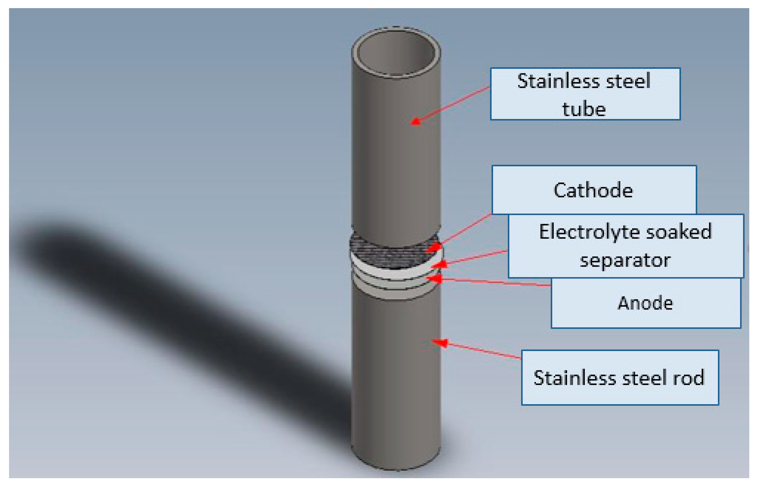
Scheme 1. Schematic depiction of the assembled Li-O2 batteries.
Batteries 05 00015 sch001
Figure 1. Voltage profile of lithium-oxygen (Li−O2) batteries with (a,c,e) palladium-filled and (b,d,f) palladium-coated carbon nanotubes (CNTs) at fixed capacities of 250 mAh.g−1, 500 mAh.g−1, and 1000 mAh.g−1, respectively, at a 250 mA.g−1 current density between 2.0 to 4.5 V.
Batteries 05 00015 g001
Figure 2. End charge/discharge voltages of (a,c,e) palladium-filled and (b,d,f) palladium-coated CNTs after full cycles to 250 mAh.g−1, 500 mAh.g−1, and 1000 mAh.g−1, respectively.
Batteries 05 00015 g002
Figure 3. Nyquist plots of (a) PF- and (b) PC-CNTs after different discharging cycles of 250 mAh.g−1 capacity; Nyquist plots of (c) PF- and (d) PC-CNTs after different discharging cycles of 500 mAh.g−1 capacity; and Nyquist plots of (e) PF- and (f) PC-CNTs after different discharging cycles of 1000 mAh.g−1 capacity. (g) Typical Nyquist plot. The batteries were cycled at 250 mA.g−1 with a current density between 2 to 4.5 V.
Batteries 05 00015 g003
Figure 4. Change of resistances after the discharging (a,c,e) Palladium-filled CNT, and (b,d,f) palladium-coated CNT cycles of 250 mAh.g−1, 500 mAh.g−1, and 1000 mAh.g−1 capacities, respectively.
Batteries 05 00015 g004
Figure 5. Fourier transform infrared (FTIR) spectra of PF- and PC-CNTs after cycling for (a) 45 cycles to 250 mAh.g−1 and (b) 15 cycles to 1000 mAh.g−1.
Batteries 05 00015 g005
Figure 6. FTIR spectra after discharging to (a) 500 mAh.g−1, (b) 1000 mAh.g−1, (c) 1500 mAh.g−1, (d) 5000 mAh.g−1, and (e) 8000 mAh.g−1. All batteries were discharged at 250 mA.g−1 between 2 to 4.5 V.
Batteries 05 00015 g006
Figure 7. SEM images after cycling of (a) PF- and (b) PC-CNT cathodes.
Batteries 05 00015 g007