
High-Fidelity Battery Model for Model Predictive Control Implemented into a Plug-In Hybrid Electric Vehicle

Abstract
: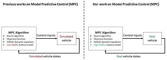
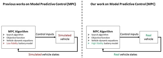
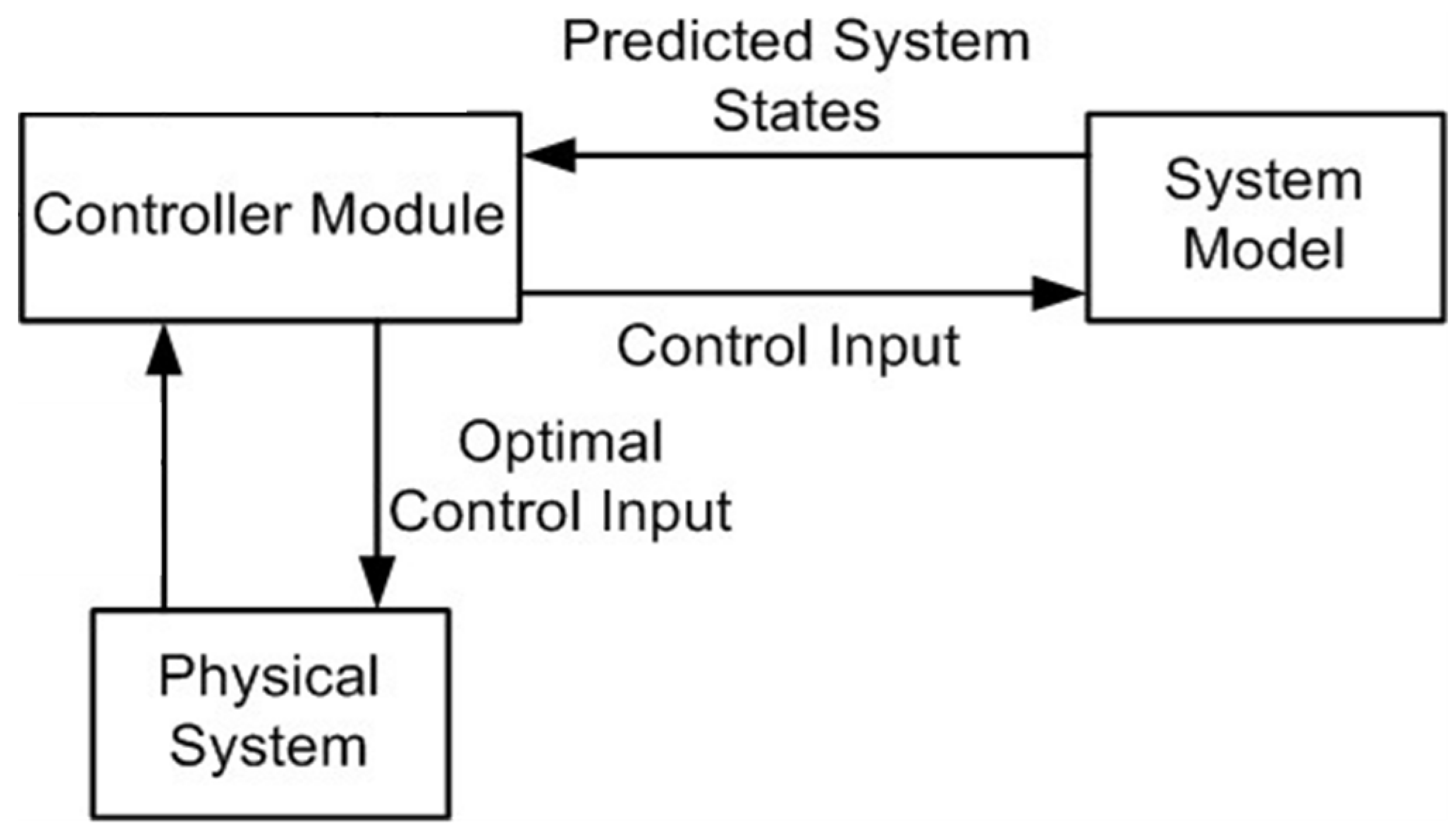
1. Introduction
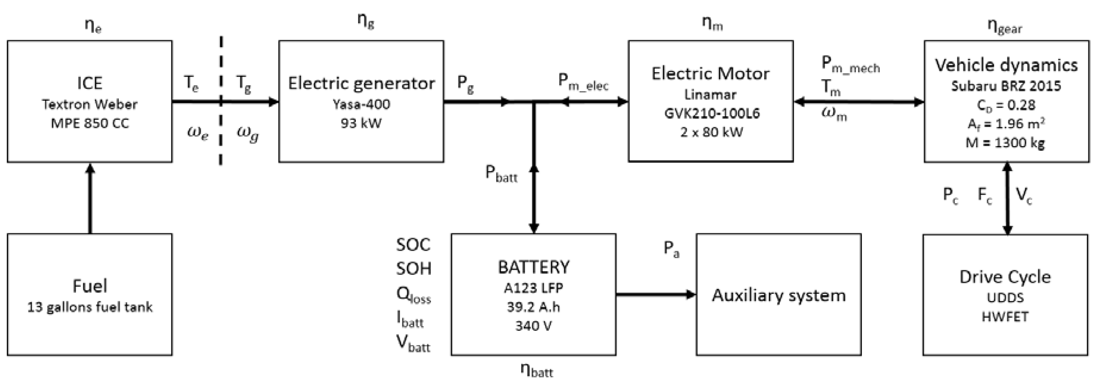
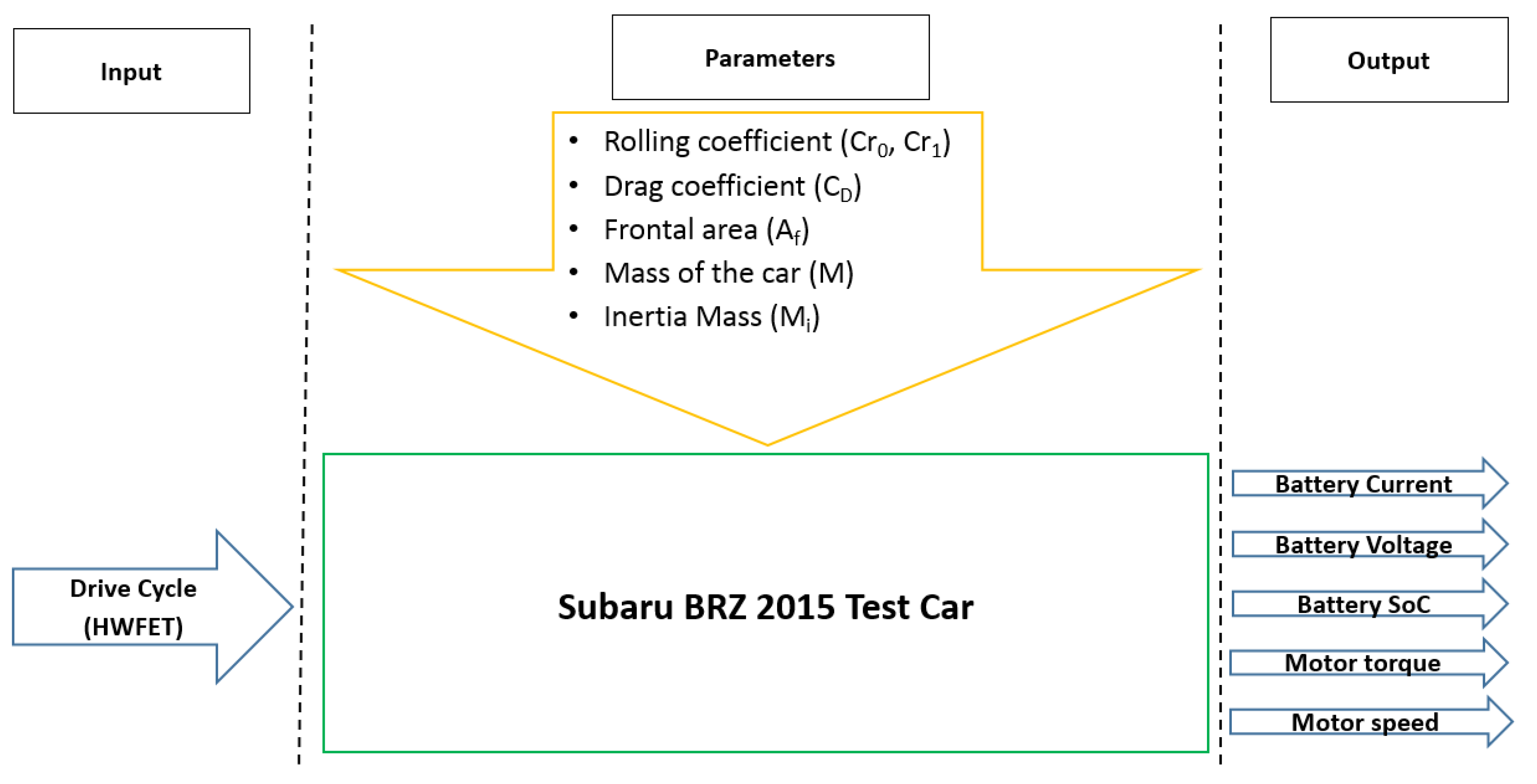
2. Vehicle Model
3. Battery
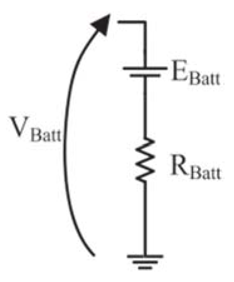
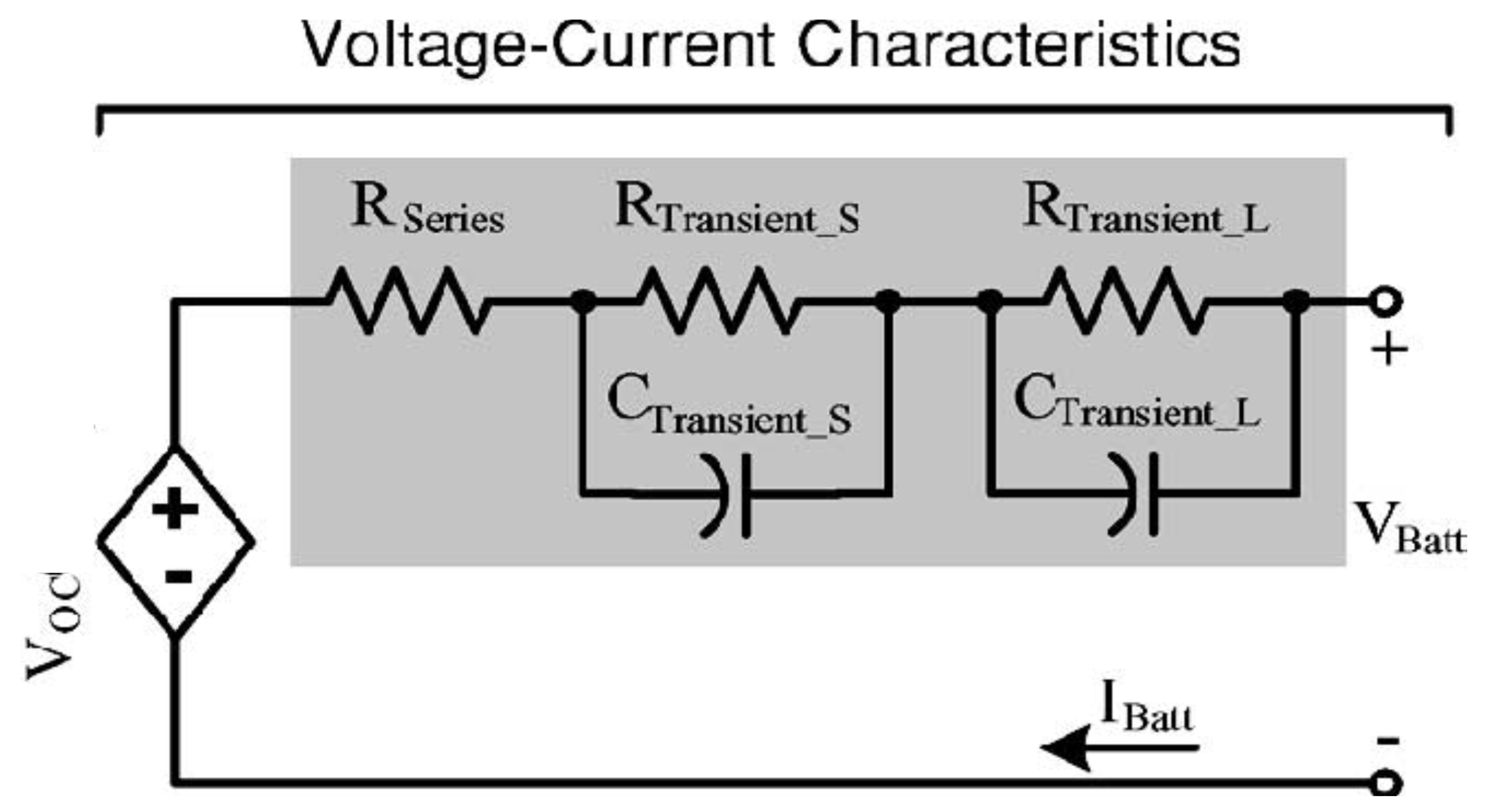
3.1. Impedance
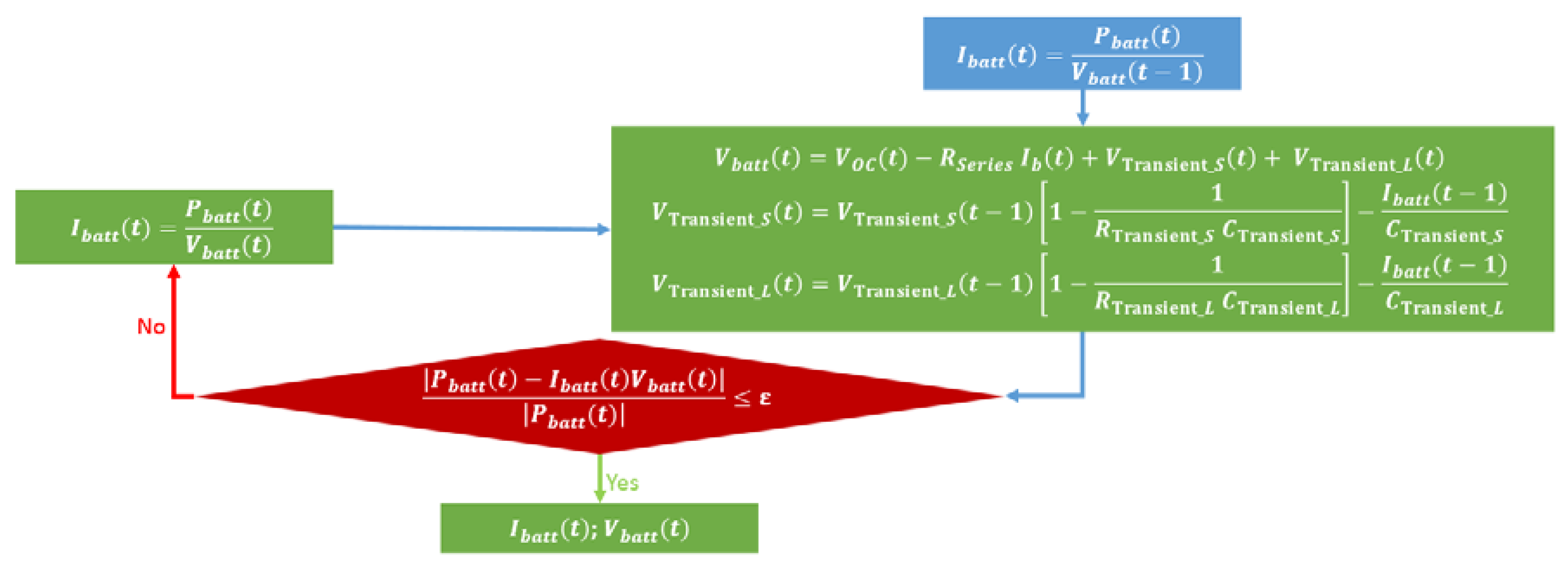
3.2. Power, Voltage and Current
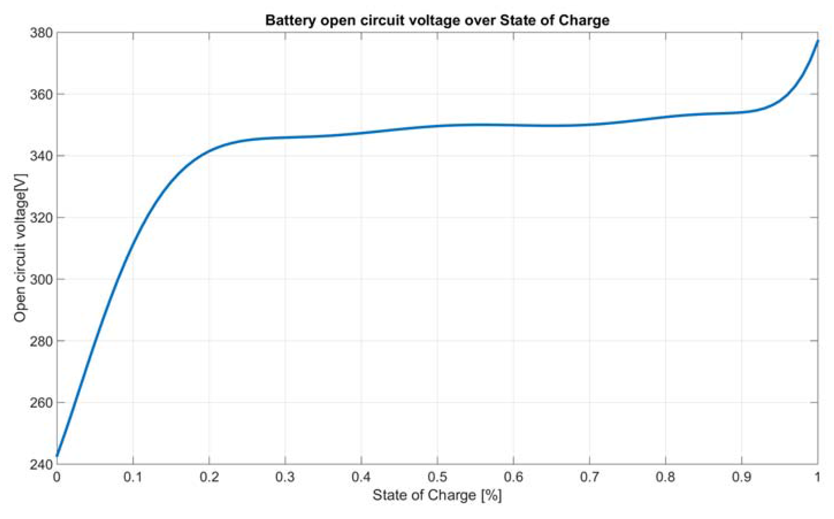
3.3. State of Charge
3.4. State of Health
4. Model Validation
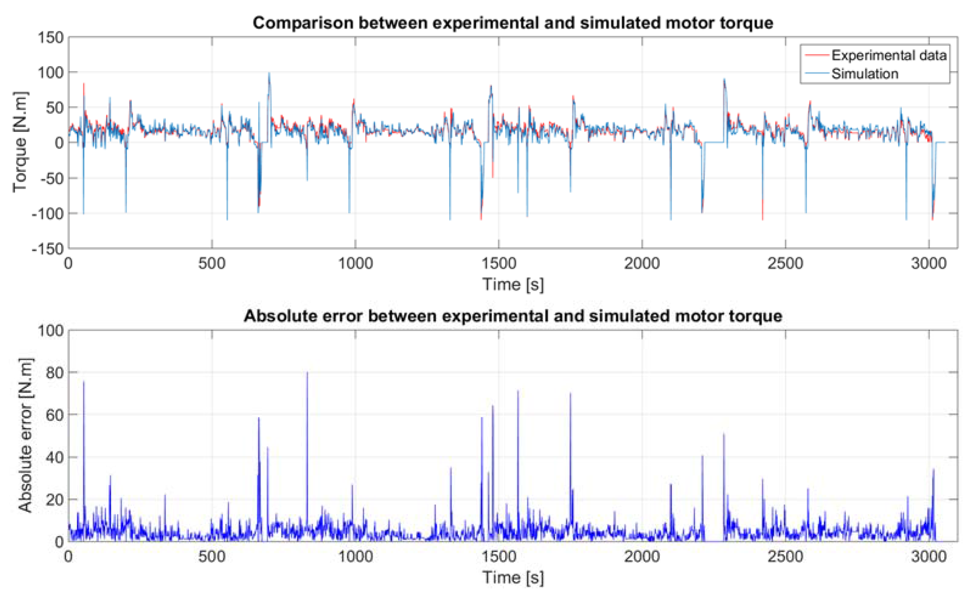
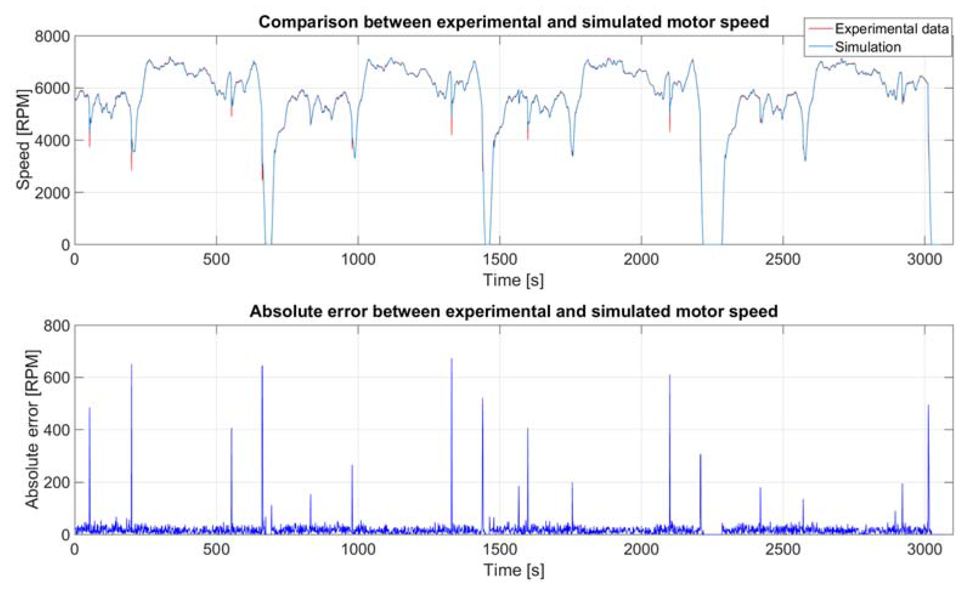
4.1. Electric Motor
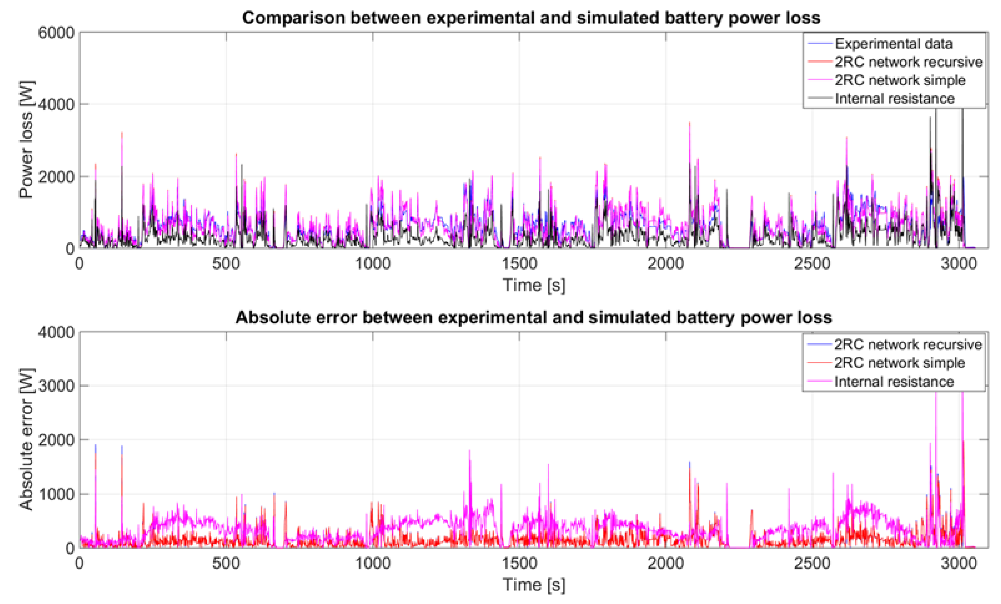
4.2. Battery
5. Conclusions
Acknowledgments
Author Contributions
Conflicts of Interest
Nomenclature
| Symbol | Name | Units |
| t | The discrete time | s |
| Δt | The step time | s |
| Fr | The rolling resistance | N |
| Fg | The grading resistance | N |
| Fw | The aerodynamic drag resistance | N |
| Fa | The acceleration resistance | N |
| Fc | The sum of every resistant force applied to the car | N |
| β | The lateral angle between the wind and car direction | rads |
| The vertical angle between the wind and car direction | rads | |
| α | The road elevation | rads |
| Pb | The power provided/received by the battery | W |
| Pm_elec | The electric power requested/supply by the electric motor | W |
| Pg_elec | The power provide by the generator | W |
| Pa | The constant power consumed by the auxiliary electric system | W |
| Pbatt | The power provided/received by the battery | W |
| Pc | The power requested/provided by the car | W |
| Pm_mech | The power provided by the motor | W |
| vc | The car speed | m/s |
| vfw | The frontal wind speed | m/s |
| vw | The wind speed | m/s |
| The car acceleration | m/s2 | |
| g | The earth gravitational constant | m/s2 |
| ωm | The motor speed | rads/s |
| ωg | The generator speed | rads/s |
| ωe | The engine speed | rads/s |
| Tg | The generator torque | N.m |
| Te | The engine torque | N.m |
| Tm | The motor torque | N.m |
| Jflwhl | The sum of the engine and generator flywheel moment of inertia | kg/m2 |
| Mi | The inertia mass due to all rotating parts | kg |
| M | The car mass | kg |
| ηbatt | The battery efficiency | - |
| ηg | The generator efficiency | - |
| ηgear | The motor gear ratio efficiency | - |
| ηm | The motor efficiency | - |
| ηe | The engine efficiency | - |
| Vbatt | The battery voltage | V |
| VOC | The battery open circuit voltage | V |
| VTransient_S | The battery short time response voltage | V |
| VTransient_L | The battery long time response voltage | V |
| Ibatt | The current provided/received by the battery | A |
| SoC | The battery state of charge | - |
| Cbatt | The battery nominal capacity | Ah |
| Qloss | The battery capacity fades | - |
| Pbloss | The battery power loss | W |
| Ebloss | The battery energy loss | Wh |
| ΔSoC | The cumulative SoC variation for a given C-rate | - |
| DOD | The depth of discharge | - |
| ncycle | The number of battery cycle | - |
| Cr0 | The car static rolling coefficient | - |
| Cr1 | The car dynamic rolling coefficient | - |
| CD | The car drag coefficient | - |
| ε0 | The gear reduction | - |
| rd | The wheels radius | m |
| Af | The car front size surface | m2 |
| ρa | The air density | kg/m3 |
| Text | The ambient absolute temperature | K |
| Pr | The ambient pressure | Pa |
| Rair | The specific gas constant for dry air | J/(kg·K) |
| R | The perfect gas constant | J/mol·K |
| Ea | The activation energy | J/mol |
| z | The power law factor | - |
| B | The pre-exponent factor | - |
Appendix A.
Appendix A.1. Vehicle Dynamics
Appendix A.2. Electric Motor
Appendix A.3. Electric Generator
Appendix A.4. Engine
References
- Shahverdi, M.; Mazzola, M.S.; Grice, Q.; Doude, M. Pareto Front of Energy Storage Size and Series HEV Fuel Economy Using Bandwidth-Based Control Strategy. IEEE Trans. Transp. Electrification 2016, 2, 36–51. [Google Scholar] [CrossRef]
- Shahverdi, M.; Mazzola, M.; Grice, Q.; Doude, M. Bandwidth-Based Control Strategy for a Series HEV with Light Energy Storage System. IEEE Trans. Veh. Technol. 2016, 66, 1040–1052. [Google Scholar] [CrossRef]
- Ranjit, A. A Model-Based Holistic Power Management Framework: A Study on Shipboard Power Systems for Navy Applications. Ph.D. Thesis, Department of Electrical and Computer Engineering, Mississippi State University, Starkville, MS, USA, 15 August 2014. [Google Scholar]
- Overall Objectives of Model Predictive Control. Course of University of California. Available online: https://chemengr.ucsb.edu/~ceweb/faculty/seborg/teaching/SEM_2_slides/Chapter_20%203-6-05.pdf (accessed on 19 March 2017).
- Qin, S.J.; Thomas, A.B. A survey of industrial model predictive control technology. Control Eng. Pract. 2003, 11, 733–764. [Google Scholar] [CrossRef]
- Malikopoulos, A. Supervisory power management control algorithms for hybrid electric vehicles: A survey. IEEE Trans. Intell. Transp. Syst. 2014, 15, 1869–1885. [Google Scholar] [CrossRef]
- Kermani, S.; Delprat, S.; Guerra, T.M.; Trigui, R. Predictive Control for HEV Energy Management: Experimental Results. In Proceedings of the IEEE Vehicle Power and Propulsion Conference (VPPC), Dearborn, MI, USA, 7–11 September 2009. [Google Scholar]
- Yu, K.; Xu, X.; Liang, Q.; Hu, Z.; Yang, J.; Guo, Y.; Zhang, H. Model Predictive Control for Connected Hybrid Electric Vehicle. Math. Probl. Eng. 2015, 2015. [Google Scholar] [CrossRef]
- Shahverdi, M.; Mazzola, M.; Abdelwahed, S.; Doude, M.; Zhu, D. MPC-based power management system for a plug-in hybrid electric vehicle for relaxing battery cycling. In Proceedings of the IEEE Transportation Electrification Conference and Expo (ITEC), Chicago, IL, USA, 27–29 June 2016. [Google Scholar]
- Di Cairano, S.; Liang, W.; Kolmanovsky, I.V.; Kuang, M.L.; Phillips, A.M. Power smoothing energy management and its application to a series hybrid powertrain. IEEE Trans. Control Syst. Technol. 2013, 21, 2091–2103. [Google Scholar] [CrossRef]
- Patil, R.M.; Filipi, Z.; Fathy, H.K. Comparison of Supervisory Control Strategies for Series Plug-In Hybrid Electric Vehicle Powertrains through Dynamic Programming. IEEE Trans. Control Syst. Technol. 2014, 22, 502–509. [Google Scholar] [CrossRef]
- Yan, F.; Wang, J.; Huang, K. Hybrid electric vehicle model predictive control torque-split strategy incorporating engine transient characteristics. IEEE Trans. Veh. Technol. 2012, 61, 2458–2467. [Google Scholar] [CrossRef]
- Patil, R.M.; Kelly, J.C.; Filipi, Z.; Fathy, H.K. A Framework for the Integrated Optimization of Charging and Power Management in Plug-in Hybrid Electric Vehicles. IEEE Trans. Veh. Technol. 2013, 62, 2402–2412. [Google Scholar] [CrossRef]
- Malikopoulos, A.A.; Smith, D.E. An optimization model for plug-in hybrid electric vehicles. In Proceedings of the ASME Internal Combustion Engine Division Fall Technical Conference, Morgantown, WV, USA, 2–5 October 2011. [Google Scholar]
- Wang, Y.; Boyd, S. Fast model predictive control using online optimization. IEEE Trans. Control Syst. Technol. 2010, 18, 267–278. [Google Scholar] [CrossRef]
- Di Cairano, S.; Bernardini, D.; Bemporad, A.; Kolmanovsky, I.V. Stochastic MPC with Learning for Driver-Predictive Vehicle Control and its Application to HEV Energy Management. IEEE Trans. Control Syst. Technol. 2014, 22, 1018–1031. [Google Scholar] [CrossRef]
- Olia, K.; Shahverdi, M.; Mazzola, M.; Sherif, A. Developing a Model Predictive Control-Based Algorithm for Energy Management System of the Catenary-Based Electric Truck. In Proceedings of the SAE International Powertrains, Fuels & Lubricants Meeting, Baltimore, MD, USA, 24–26 October 2016. [Google Scholar]
- Borhan, H.; Vahidi, A.; Phillips, A.; Kuang, M.; Kolmanovsky, I. Predictive energy management of a power-split hybrid electric vehicle. In Proceedings of the IEEE American Control Conference (ACC), St. Louis, MO, USA, 10–12 June 2009. [Google Scholar]
- Santucci, A.; Sorniotti, A.; Lekakou, C. Power split strategies for hybrid energy storage systems for vehicular applications. J. Power Sources 2014, 258, 395–407. [Google Scholar] [CrossRef]
- Borhan, H.; Vahidi, A. Model predictive control of a power-split Hybrid Electric Vehicle with combined battery and ultracapacitor energy storage. In Proceedings of the IEEE American Control Conference (ACC), Baltimore, MD, USA, 30 June–2 July 2010. [Google Scholar]
- Borhan, H.; Zhang, C.; Vahidi, A.; Phillip, A.; Kuang, M.; Di Cairano, S. Nonlinear Model Predictive Control for power-split Hybrid Electric Vehicles. In Proceedings of the IEEE Conference on Decision and Control (CDC), Atlanta, GA, USA, 15–17 December 2010. [Google Scholar]
- Santucci, A.; Sorniotti, A.; Lekakou, C. Model Predictive Control for the Power-Split between Supercapacitor and Battery for Automotive Applications. In Proceedings of the IEEE International Electric Vehicle Conference (IEVC), Santa Clara, CA, USA, 23–25 October 2013. [Google Scholar]
- Liu, C.; Liu, L. Optimal Power Source Sizing of Fuel Cell Hybrid Vehicles based on Pontryagin’s Minimum Principle. Int. J. Hydrog. Energy 2015, 40, 8454–8464. [Google Scholar] [CrossRef]
- Liu, C.; Liu, L. PMP-Based Fuel Cell Hybrid Vehicle Power Management Considering Battery Current Constraint and Battery Health Analysis. In Proceedings of the SAE World Congress & Exhibition, Detroit, MI, USA, 21–23 April 2015. [Google Scholar]
- IDC Technologies: Industrial Automation; The IDC Engineers & Ventus Publishing ApS: Frederiksberg, Danemark, 2012.
- Plett, G.L. Extended Kalman filtering for battery management systems of LiPB-based HEV battery packs: Part 2. Modeling and identification. J. Power Source 2004, 134, 262–276. [Google Scholar] [CrossRef]
- Plett, G.L. Extended Kalman filtering for battery management systems of LiPB-based HEV battery packs: Part 3. State and parameter estimation. J. Power Source 2004, 134, 277–292. [Google Scholar] [CrossRef]
- Mazzola, M.S.; Shahverdi, M. Li-Ion Battery Pack and Applications. In Rechargeable Batteries; Springer: New York, NY, USA, 2015; pp. 455–476. [Google Scholar]
- Shahverdi, M.; Mazzola, M.; Doude, M.; Grice, Q. A hybrid electric vehicle with minimal energy storage system. In Proceedings of the IEEE Transportation Electrification Conference and Expo (ITEC), Dearborn, MI, USA, 15–18 June 2014. [Google Scholar]
- Einhorn, M.; Conte, F.V.; Kral, C.; Fleig, J. Comparison, Selection, and Parameterization of Electrical Battery Models for Automotive Applications. IEEE Trans. Power Electron. 2013, 28, 1429–1437. [Google Scholar] [CrossRef]
- He, H.; Xiong, R.; Fan, J. Evaluation of Lithium-Ion Battery Equivalent Circuit Model for State of Charge Estimation by an Experimental Approach. Energies 2011, 4, 582–598. [Google Scholar] [CrossRef]
- Chen, M.; Rincon-Mora, G.A. Accurate Electrical Battery Model Capable of Predicting Runtime and I-V Performance. IEEE Trans. Energy Convers. 2006, 21, 504–511. [Google Scholar] [CrossRef]
- Li, J.; Mazzola, M.S. Accurate battery pack modeling for automotive applications. J. Power Sources 2013, 237, 215–228. [Google Scholar] [CrossRef]
- Wang, J.; Liu, P.; Hicks-Garner, J.; Sherman, E.; Soukiazian, S.; Verbrugge, M.; Tataria, H.; Musser, J.; Finamore, P. Cycle-life model for graphite-LifePO4 cells. J. Power Sources 2010, 196, 3942–3948. [Google Scholar] [CrossRef]
- Ebbesen, S.; Elbert, P.; Guzzella, L. Battery state-of-health perceptive energy management of hybrid electric vehicles. IEEE Trans. Veh. Technol. 2012, 61, 2893–2900. [Google Scholar] [CrossRef]
- National Programme on Technology Enhanced Learning (NPTEL), Electrical Engineering. Introduction to Hybrid and Electric Vehicles; Module 2: Dynamics of Electric and Hybrid vehicles; Lecture 3: Motion and Dynamic Equations for Vehicles. Available online: http://nptel.ac.in/courses/108103009/download/M2.pdf (accessed on 19 March 2017).
- Motevalli, V. EcoCar2: Plug-into the future. In Introduction to Hybrid-Electric Vehicles; Advanced Vehicle Technology Competition (AVTC) of Purdue University: West Lafayette, IN, USA, 2013. [Google Scholar]
- Thogersen, M.L. Modeling of the Variation of Air Density with Altitude through Pressure, Humidity, and Temperature; EMD International A/S: Aalborg, Denmark, 2005. [Google Scholar]
- Muench, S. Vehicle Dynamics. CEE Course. December 2016. Available online: www.courses.washington.edu/cee320w/lectures/Vehicle%20Dynamics.ppt (accessed on 19 March 2017).


| Power-Train Component | Name | Characteristics |
|---|---|---|
| ESS | LFP prismatic cells from A123 | Capacity = 39.2 Ah; nominal voltage = 340 V; nominal energy = 13.3 kWh; configuration: 7×15s2p. |
| Engine | Model MPE850 from Weber | 41 kW, 2 cylinders, 850 cc. |
| Generator | Model YASA-400 | 93 kW, axial flux permanent magnet. |
| Motors Unit | Model GVK210-100L6 from Linamar | 2 × 80 kW, unit ratio = 8.49. |
| Vehicle dynamics | 2015 Subaru BRZ Limited | Drag coefficient = 0.28; frontal area = 1.9695 m2; PHEV mass = 1300 kg; wheel radius = 0.3 m. |
| Name | Value | Unit |
|---|---|---|
| RSeries | 0.1094 | Ohm (Ω) |
| RTransient_S | 0.1111 | Ohm (Ω) |
| CTransient_S | 0.4227 | kilo Farrad (kF) |
| RTransient_L | 0.1115 | Ohm (Ω) |
| CTransient_L | 10.196 | kilo Farrad (kF) |
| Electric Motor | Average Absolute Error | Standard Deviation Absolute Error |
|---|---|---|
| Speed | 18 RPM | 37 RPM |
| Torque | 4.4 N.m | 4.3 N.m |
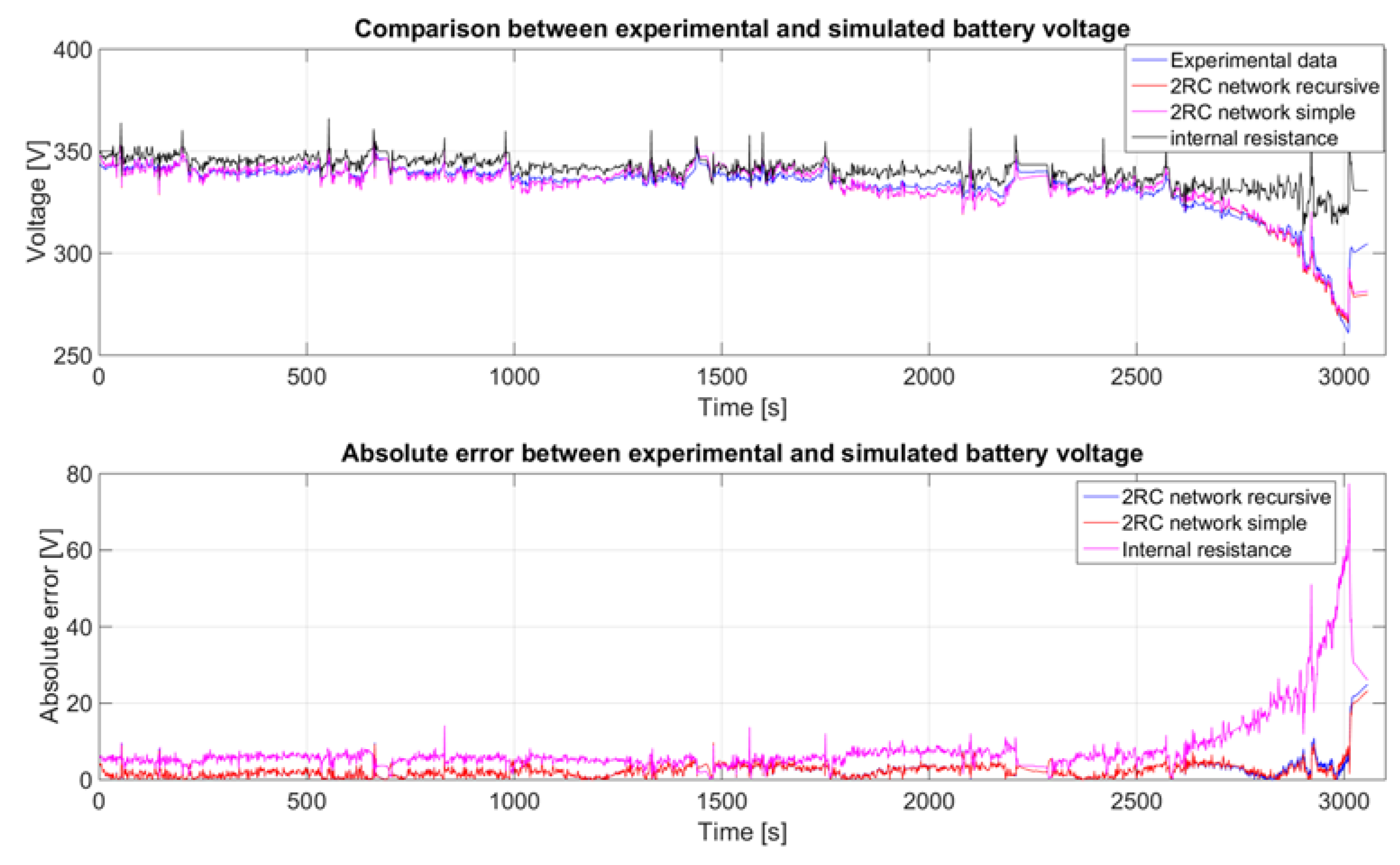
| Battery Model | Average Absolute Error | Improvement Factor | Standard Deviation Absolute Error |
|---|---|---|---|
| Internal resistance | 8.0 V | - | 8.0 V |
| Two RC network recursive | 2.5 V | 3.200 | 2.8 V |
| Two RC network simple | 2.5 V | 3.200 | 2.7 V |
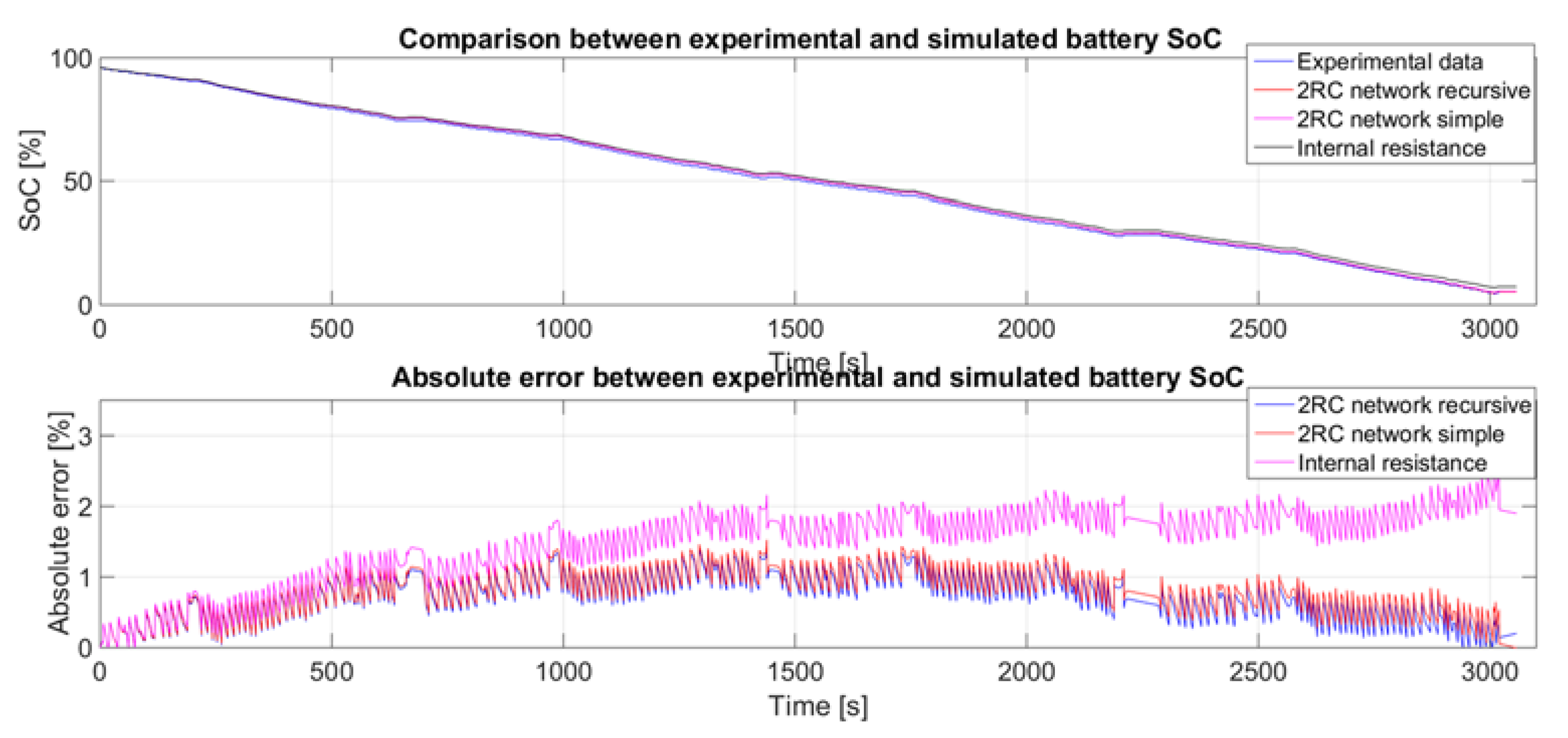
| Battery Model | Average Absolute Error | Improvement Factor | Standard Deviation Absolute Error |
|---|---|---|---|
| Internal resistance | 1.5% | - | 0.5% |
| Two RC network recursive | 0.7% | 2.142 | 0.3% |
| Two RC network simple | 0.8% | 1.875 | 0.3% |
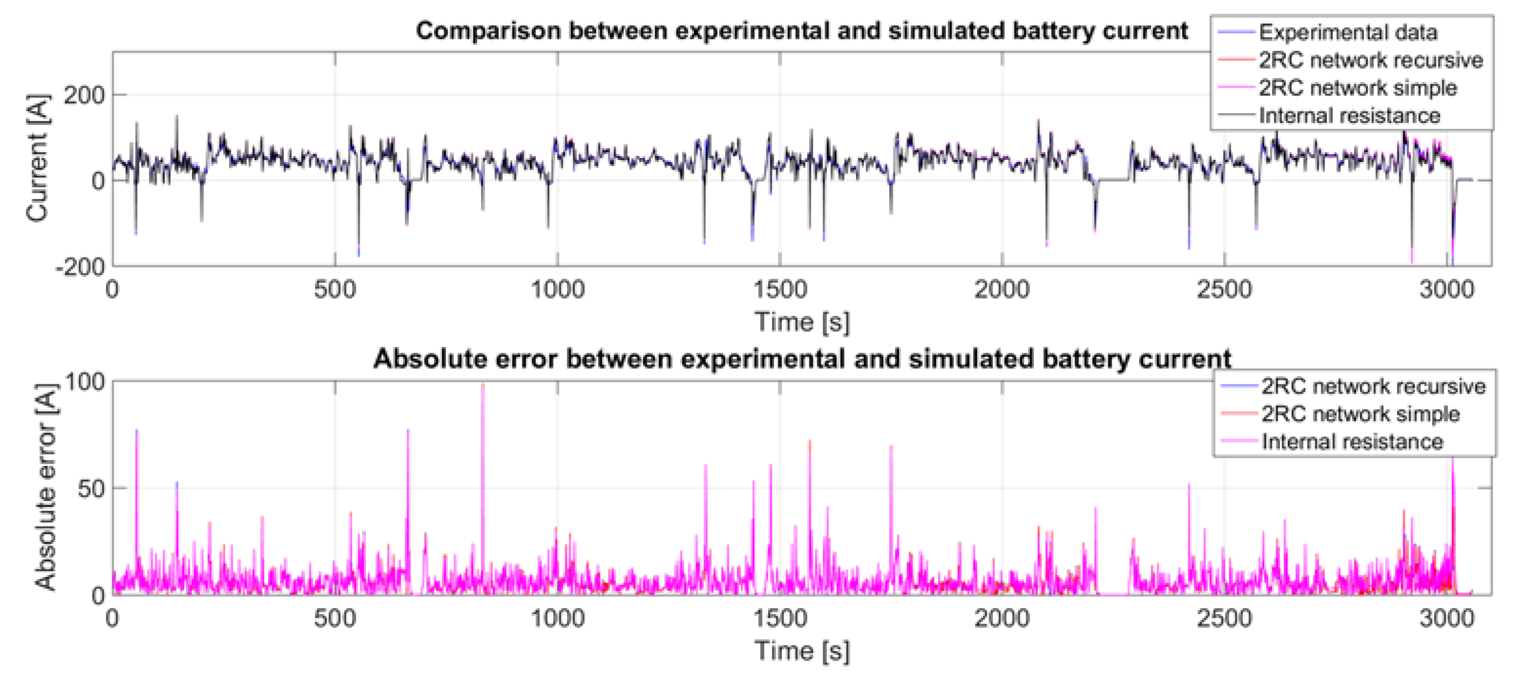
| Battery Model | Average Absolute Error | Improvement Factor | Standard Deviation Absolute Error |
|---|---|---|---|
| Internal resistance | 6.3 A | - | 7.0 A |
| Two RC network recursive | 6.2 A | 1.016 | 7.0 A |
| Two RC network simple | 6.2 A | 1.016 | 6.9 A |
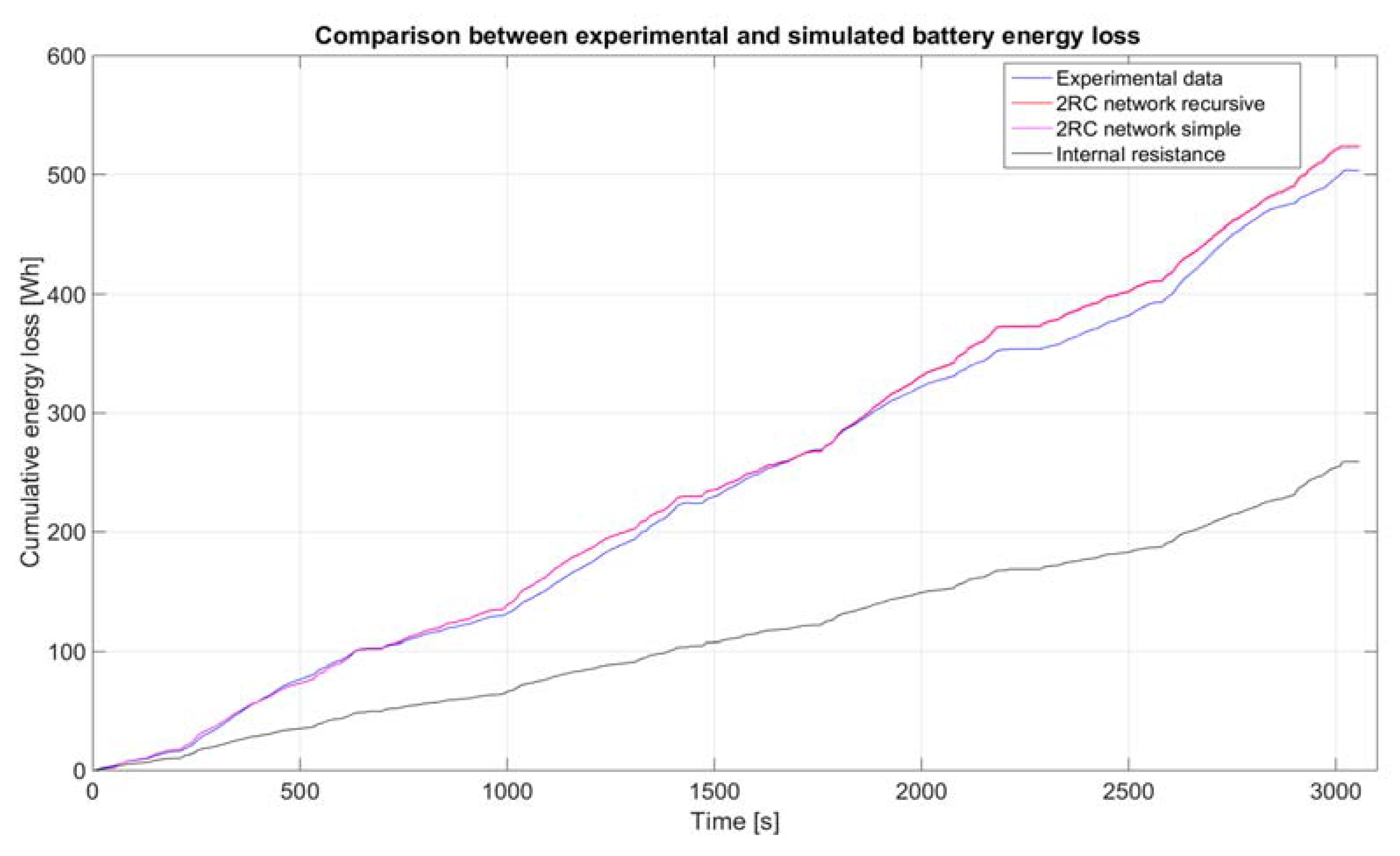
| Battery Model | Average Absolute Error | Improvement Factor | Standard Deviation Absolute Error |
|---|---|---|---|
| Internal resistance | 325.9 W | - | 231.5 W |
| Two RC network recursive | 153.6 W | 2.122 | 181.9W |
| Two RC network simple | 152.5 W | 2.137 | 178.4 W |
© 2017 by the authors. Licensee MDPI, Basel, Switzerland. This article is an open access article distributed under the terms and conditions of the Creative Commons Attribution (CC BY) license (http://creativecommons.org/licenses/by/4.0/).
Share and Cite
Sockeel, N.; Shahverdi, M.; Mazzola, M.; Meadows, W. High-Fidelity Battery Model for Model Predictive Control Implemented into a Plug-In Hybrid Electric Vehicle. Batteries 2017, 3, 13. https://doi.org/10.3390/batteries3020013
Sockeel N, Shahverdi M, Mazzola M, Meadows W. High-Fidelity Battery Model for Model Predictive Control Implemented into a Plug-In Hybrid Electric Vehicle. Batteries. 2017; 3(2):13. https://doi.org/10.3390/batteries3020013
Chicago/Turabian StyleSockeel, Nicolas, Masood Shahverdi, Michael Mazzola, and William Meadows. 2017. "High-Fidelity Battery Model for Model Predictive Control Implemented into a Plug-In Hybrid Electric Vehicle" Batteries 3, no. 2: 13. https://doi.org/10.3390/batteries3020013
APA StyleSockeel, N., Shahverdi, M., Mazzola, M., & Meadows, W. (2017). High-Fidelity Battery Model for Model Predictive Control Implemented into a Plug-In Hybrid Electric Vehicle. Batteries, 3(2), 13. https://doi.org/10.3390/batteries3020013