1. Introduction
New battery technologies offer power and energy densities that make it possible to construct applications with impressive performance. Lithium-ion batteries have, for example, made it possible to produce electric vehicles with reasonable range and there are expectations that the next-generation batteries such as zinc (Zn)–air, lithium–air and fuel flow batteries could provide further strides towards even more competitive products, promoting, among other things, extended electromobility in the future [
1,
2]. As for all new technologies, it is important to know and understand the potential risks associated with their applications. Lithium-ion batteries have, in general, a good safety record; however, the cells contain reactive materials as well as a volatile and flammable electrolyte. A so-called thermal runaway can occur in Li-ion cells, resulting in excessive heat, emission of toxic gas and eventually fire and/or explosion [
3,
4]. Safety aspects for lithium-ion batteries have been studied using various types of abuse tests such as overcharge, overdischarge, short circuiting, external heating and fire [
5,
6]. Such tests are very important in order to evaluate and minimize risks, not only for the different products using these batteries but also for the storage and transportation of the cells as well as for recycling. The risks associated with transporting lithium-ion cells by air have, for example, been a focus recently [
7].
Among new developing technologies, the lithium–air battery has attracted considerable attention due to its prospected very high specific energy. The Li–air battery is still far from being commercialized and certain safety concerns are challenging [
8]. In contrast to lithium-ion batteries, metal–air batteries in general may offer the possibility to limit battery reactions by stopping the air supply to the cell. One such battery type, the Zn–air battery, is promising in that the energy density is good, typically of the order of 200 Wh/kg or more, the materials used are abundant and the costs of production are expected to be comparatively low [
9,
10]. The battery has a hydroxide electrolyte, a Zn anode and atmospheric oxygen is reduced at the cathode. The cell is in many respects similar to a fuel cell, and electricity is produced as long as fuel, in this case Zn, and oxygen are available. The cell reactions are:
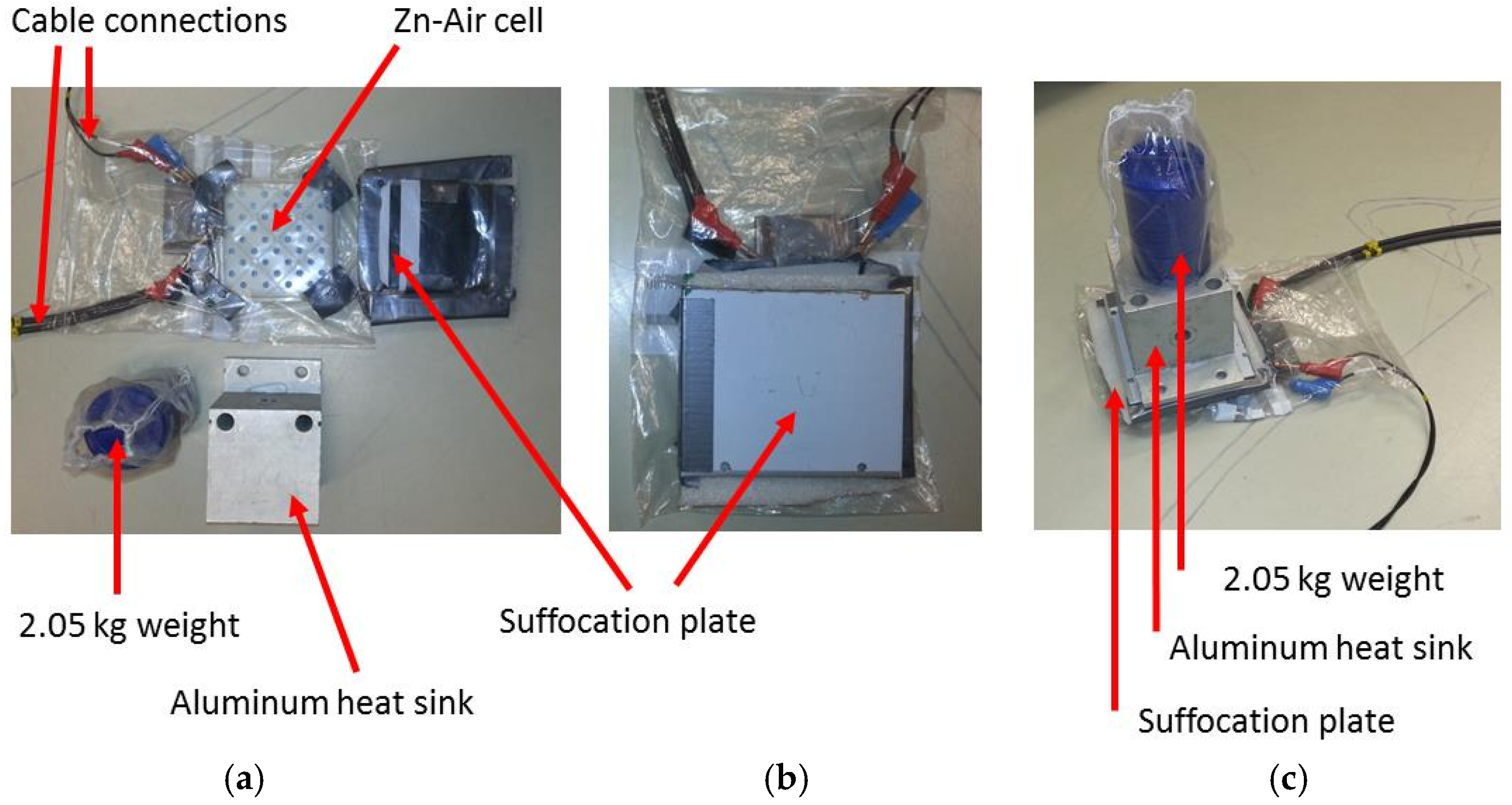
Zn–air batteries are regarded to be very safe, and risks are commonly only associated with possible leakage of the hydroxide electrolyte and the formation of hydrogen by Zn corrosion. Early types of Zn–air batteries contained a mercury amalgam but the present generation of these batteries is mercury-free. Short circuit currents are generally expected to be low, and this should minimize risks associated with external short circuits, but traditional abuse tests on these types of cells are rare. In this study, primary Zn–air batteries were investigated regarding overcurrent and controlled air supply flow in order to evaluate risks and possibilities related to battery safety. Besides performing an overcurrent abuse test study on Zn–air batteries, the study particularly addresses suffocation as a means to stop battery reactions and thus to cause battery shutdown. For metal–air batteries this is a principal additional safety function that is not available in other battery technologies such as lead-acid, nickel–metal hydride (NiMH) and lithium-ion batteries.
3. Results and Discussion
In all tests, a 60-s rest phase prior the start of the discharging was used for monitoring, and a longer rest phase of 900 s was used after discharging to record the recovery of the cell potential. Note that the given times in the paper are referring to the time from the start of discharge, i.e., add 60 s to the value, to correspond to the time scales in the figures.
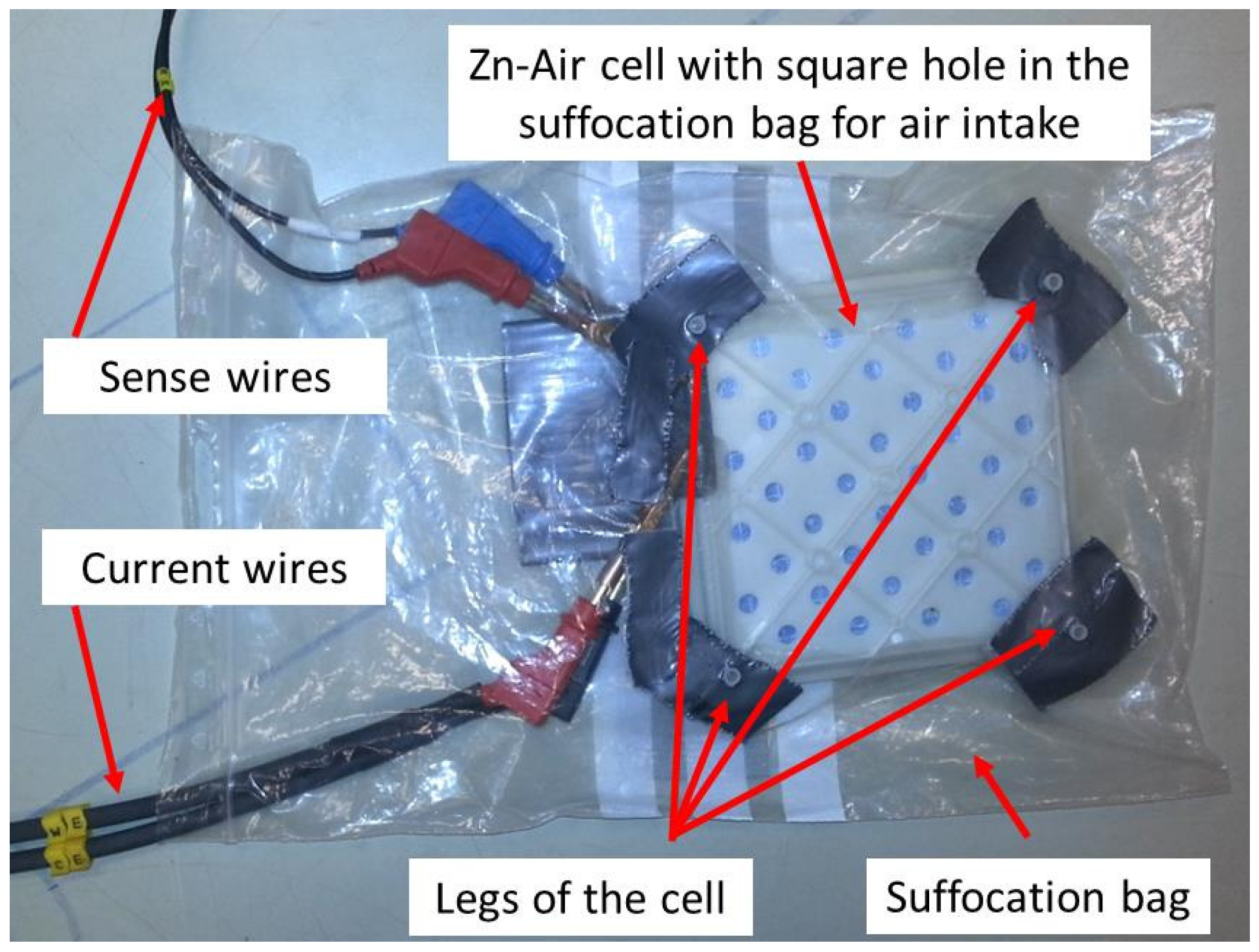
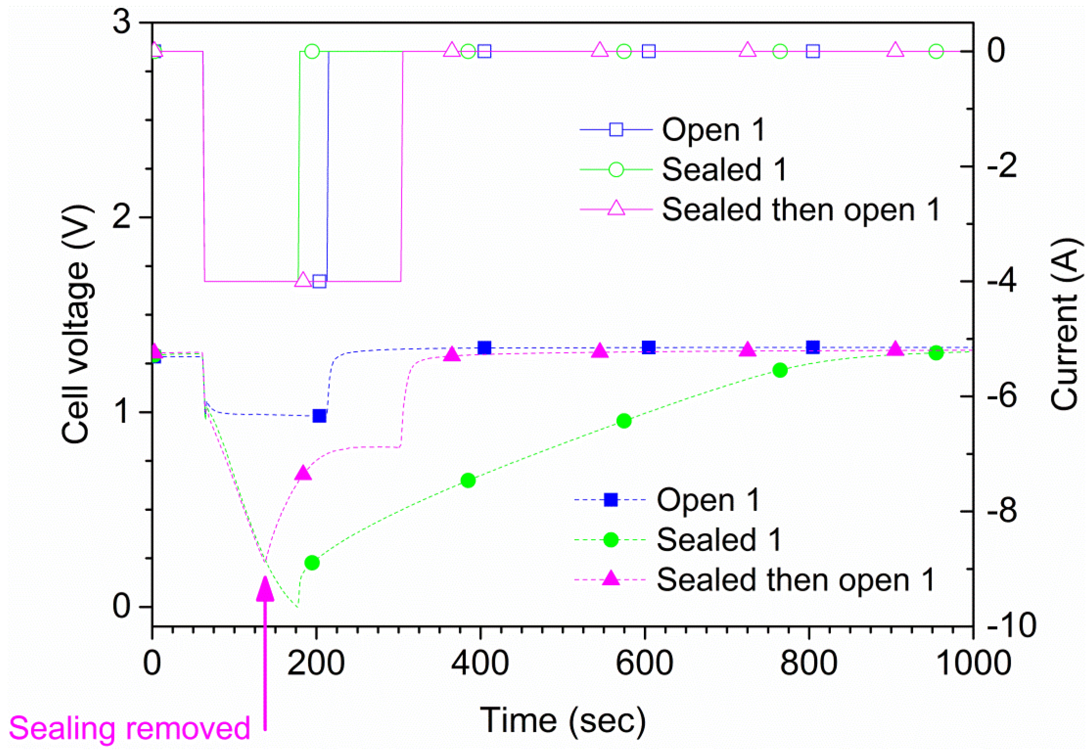
The maximum allowed continuous discharge current of the cells is 4 A according to the manufacturer. Two types of measurements were performed. For the first type, each cell was discharged at 4 A both in open air and suffocated for 150 s or until the cell potential reached 0 V. A total of four tests were conducted for each cell, two in open air and two suffocated. In
Figure 4, the results for one of the cells (cell 1) are shown. The time to reach 0 V during suffocation was 120 s. In the second type of measurement, the sealing of the cell was lifted at a pre-determined time. Also, in this type of experiment, an initial 60 s rest period was used followed by a 240 s, 4 A discharge phase where the suffocation was lifted 75 s after discharge initiation (135 s from the test start), as shown in
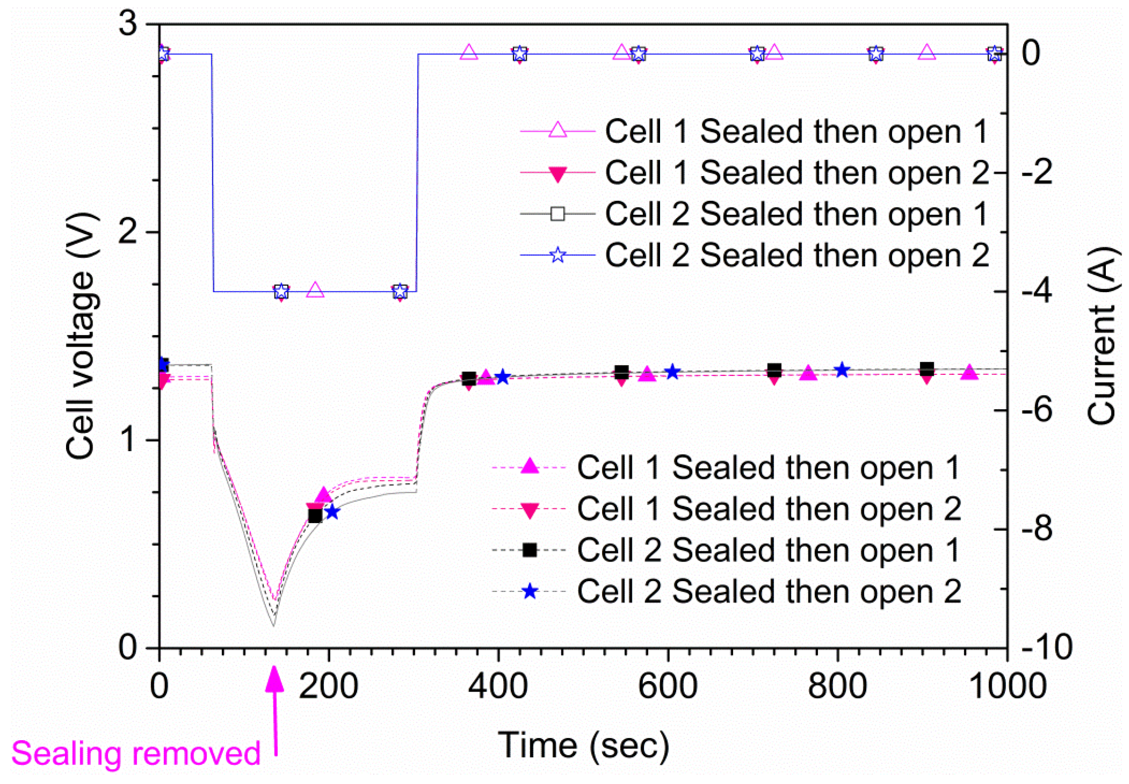
Figure 4. These results were reproducible; repeated tests on two samples are shown in
Figure 5. The experiments show that the cell recovered rapidly to the original
OCV after suffocation, provided air access was granted. When the cell is open to air, the voltage recovers rapidly; when the cell is sealed during the whole experiment (green curve/symbols in
Figure 4), the recovery is slow. The small differences shown in
Figure 5 are due to minor differences regarding the voltage when the sealing was removed.
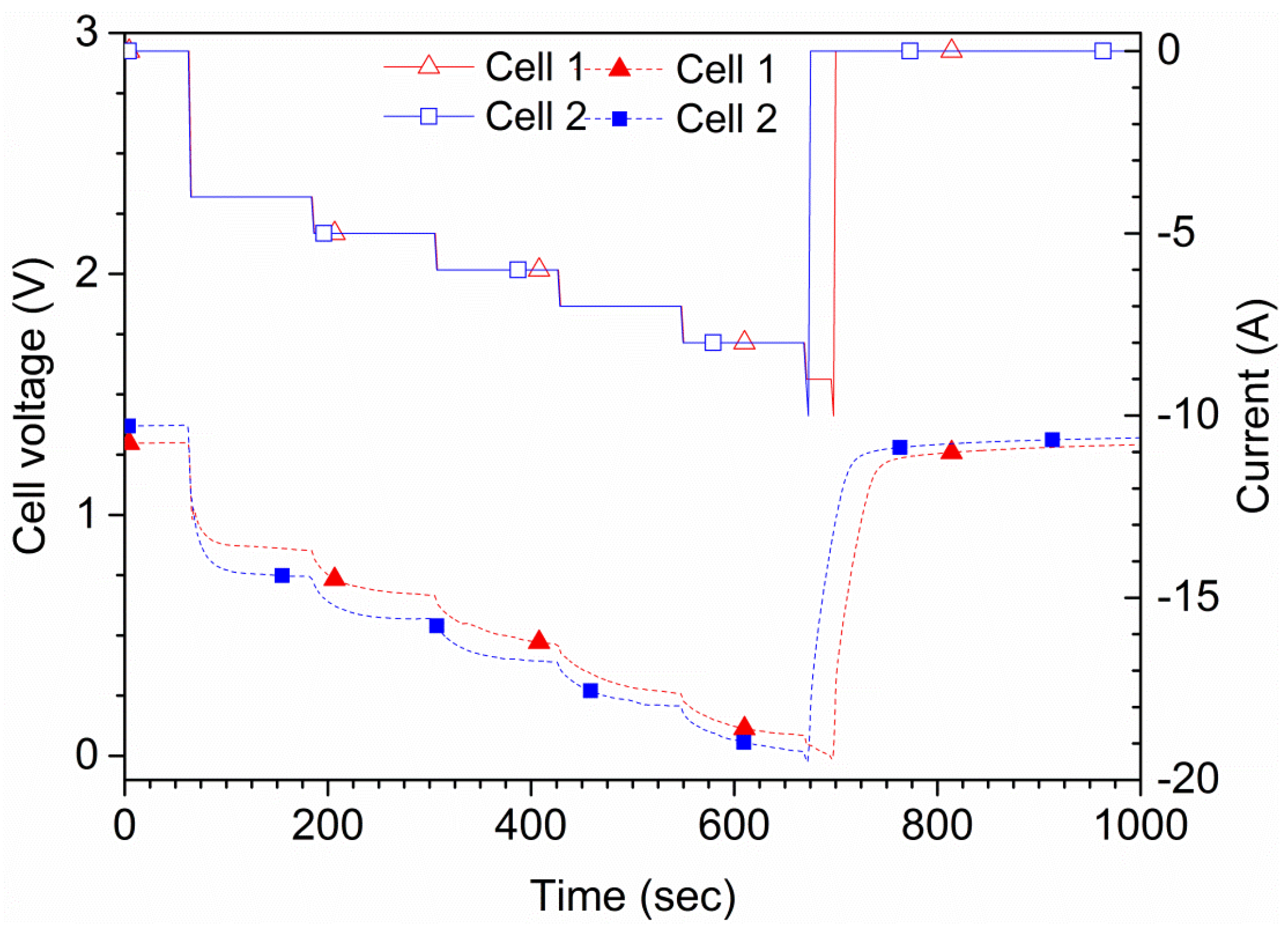
The tests were also performed in order to find the maximum current that a cell can sustain for 2 min, as shown in
Figure 6. This current was later used for maximum discharge tests. During the tests, the cell was discharged by a current of 4, 5, 6, 7, 8, 9 and 10 A for 2 min each, in this order. A cutoff triggered at 0.0 V cell potential was used, which stopped the running step and jumped to the next in case 0.0 V was reached. One of the cells showed a voltage of 76 mV at the end of the 8 A step; when changing to 10 A, the voltage rapidly reached 0 V and the test stopped. The other cell shown in
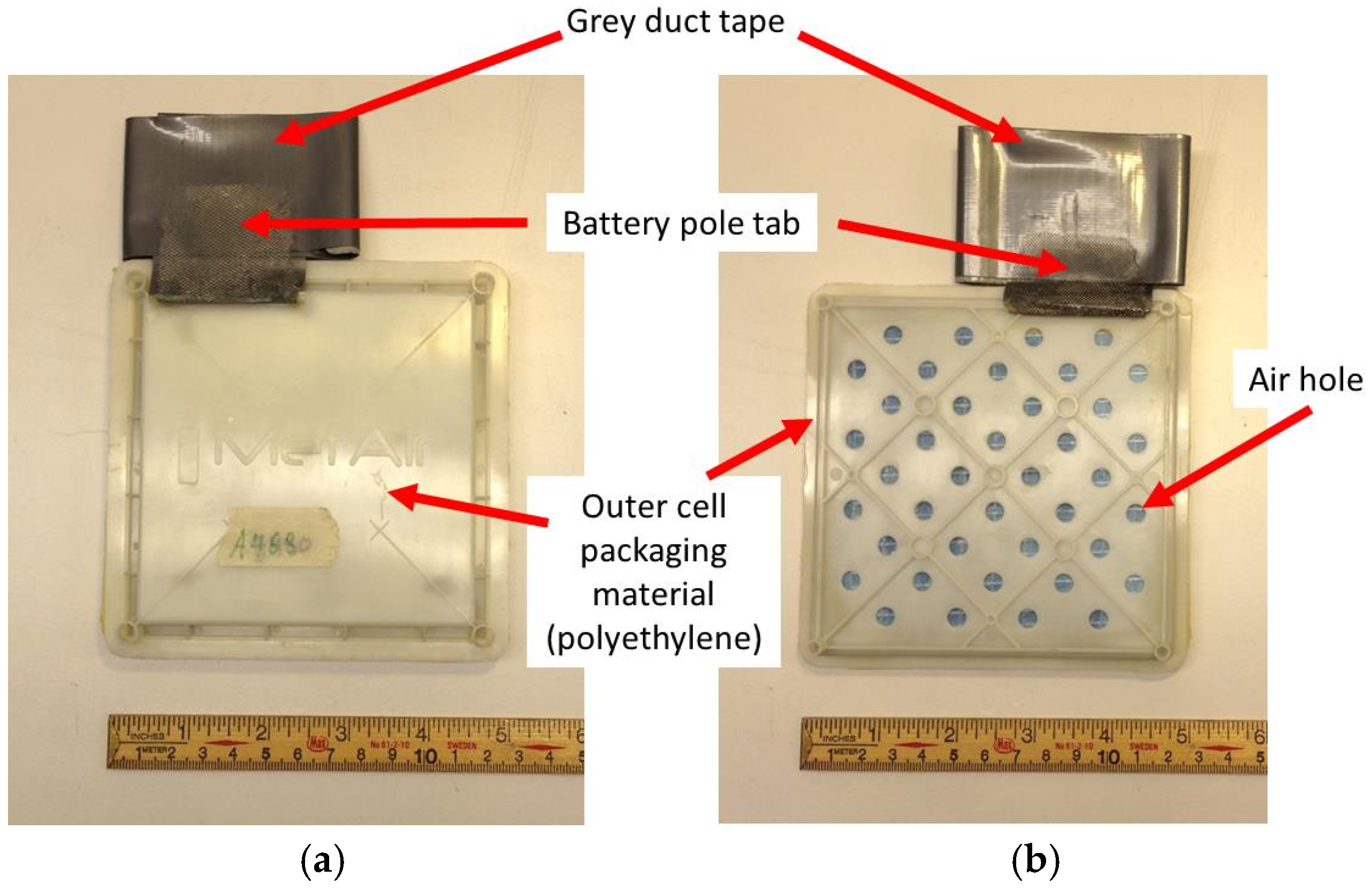
Figure 6 showed a larger initial voltage drop and had a lower potential profile during the complete tests. That cell also passed the 8 A step, but not the 10 A step. Therefore, the maximum continuous current is estimated to be 8 A. This current level was used for the additional tests. Since the cells are rated for 4 A, using currents above this value is, by definition, an overcurrent. The short circuit current,
Isc, i.e., the current through an external conductor with negligible resistance connecting the battery pole tabs, depends on, e.g., the current path size through the battery tabs and the rate of the electrochemical reactions creating the short circuit current.
Isc is, in general, time-dependent (as well as dependent on various additional parameters, e.g., cell type and design, temperature, aging, state of charge (
SOC)) and was not investigated in this study since we needed a continuous current for our measurements; the current used was therefore lower than
Isc.
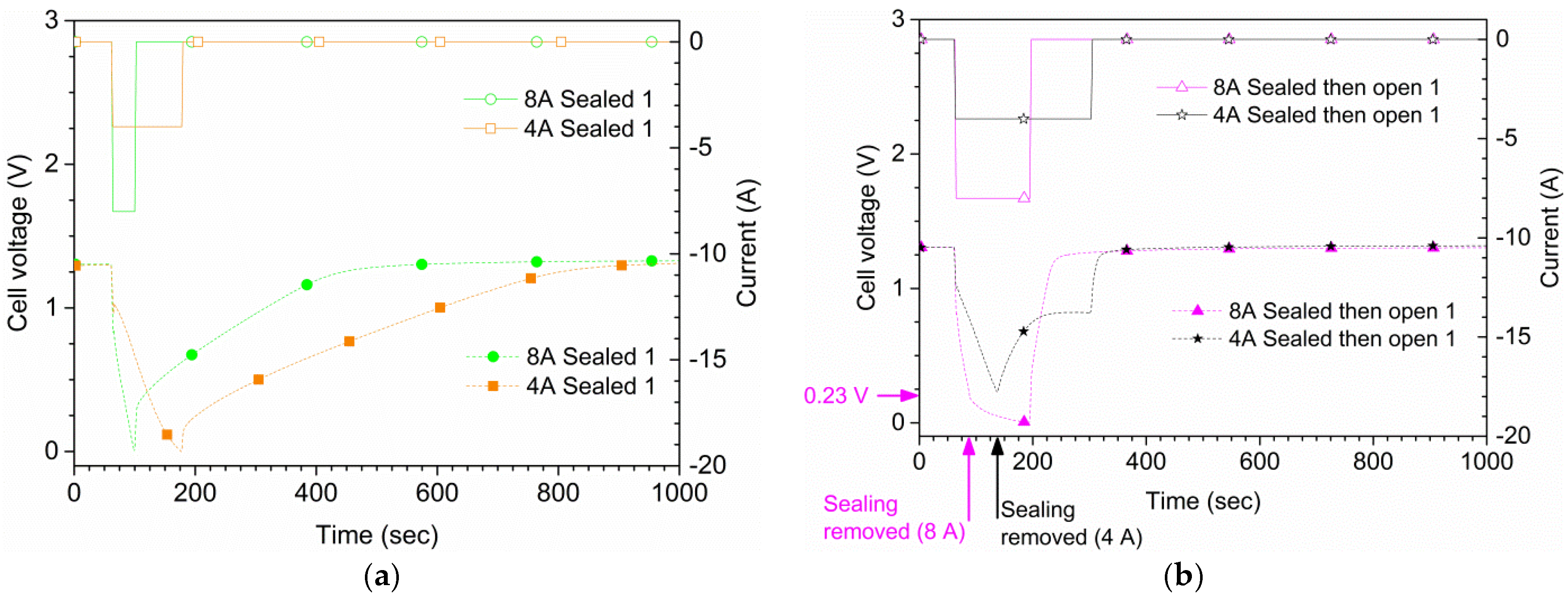
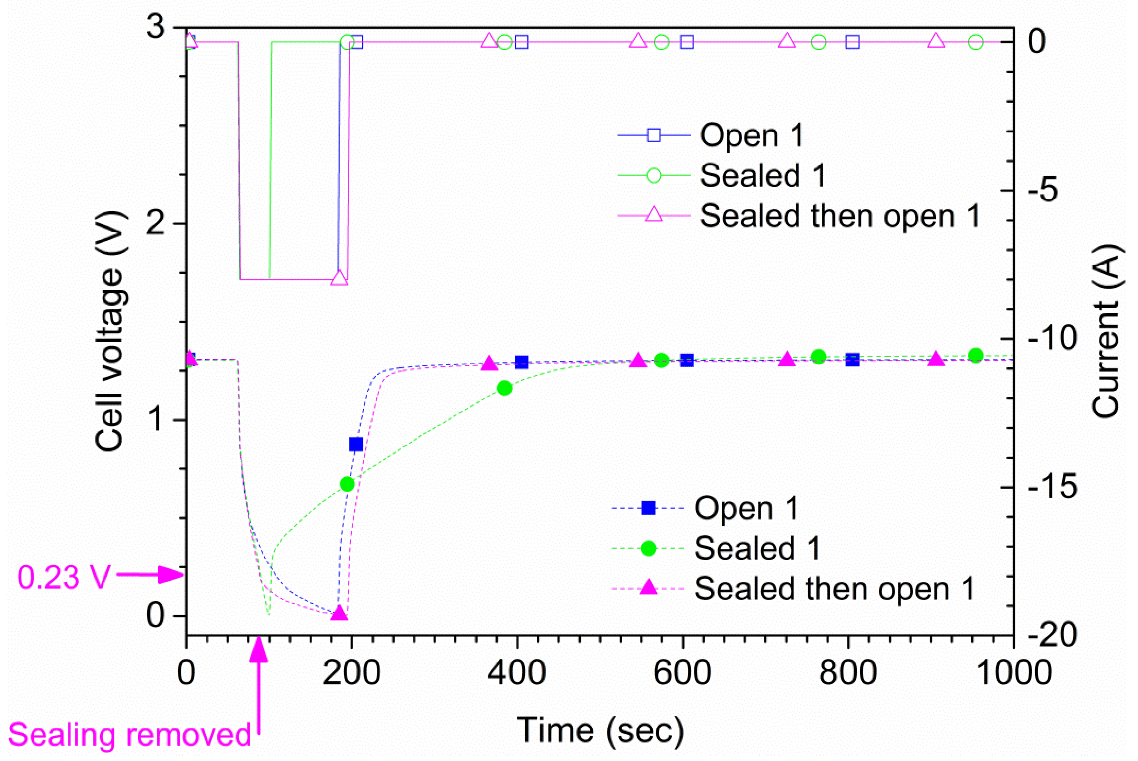
Figure 7 shows the results for the same type of measurements as in
Figure 4 but with an 8 A discharge current. With suffocation, 0.0 V was reached 36 s after the start of the discharge in the first run, and after 33 s in a second run (not shown). In open air, the cell delivered 8 A in 120 s; however, by the end of the discharge the voltage was only 14 mV. For the second run of 8 A in open air, the cell reached 0.0 V after 107 s, and did thus not reach the 120 s goal. In the sealed and open air run, the seal was removed at around 0.23 V, 27 s after the start of the discharge. The 8 A current was maintained in this case until 0.0 V was reached 135 s after the start of the discharge. A comparison between 4 A and 8 A is shown in
Figure 8 for the three air supply cases.
The suffocation experiments show that the potential of the cells rapidly goes to zero when the air supply is stopped. Starting from the cell reactions, Equations (1)–(4), our calculations show that the required air flow to the cell is 0.56 mL/s at a standard temperature and pressure, for a discharge current of 1.0 A. In the present case, for the 4 A discharge, the cell reached 0.0 V after approximately 120 s, corresponding to an air volume of 269 mL trapped inside cell. This volume is very close to the actual volume of the prismatic cell. For the 8 A overcurrent case, the suffocation resulted in a zero potential value already after 36 s, corresponding to an air volume of 161 mL. Of course, in this case the cell potential was decreasing also in open air, so the lower value is not unexpected. It should also be noted that the cell potential recovered quickly when the cells were re-exposed to air.
One of the important safety questions tested is: if the air supply at the cathode is stopped, is it possible to stop the battery operations efficiently in case of an emergency situation? The obtained results show that suffocation of the cell can indeed bring the cell potential to zero within a short period of time and stop further propagation of the internal reactions. The procedure is mainly limited by the volume of the cell packaging. The shutdown time is a function of the available air volume within the battery cell, and in the case of a battery pack also including the free air inside the battery system. For example, for a battery module/pack using a stack of Zn–air cells electrically connected in series and/or parallel, the amount of free air in the battery pack, arising from, e.g., interconnecting cell spacing, should be minimized in order for suffocation to be efficient. However, free air volumes are typically minimized anyway in order to achieve a compact battery pack size. Anyhow, some additional free air volumes might be useful and required for thermal management (cooling/heating) of the battery cells. The shutdown rate using suffocation may also be improved by lowering the available air volume by removing air from the system. In case of an emergency shutdown, the need of reducing the amount of oxygen in the free air volume can be supported by other methods, e.g., by a pump which could rapidly empty the free air volume; however, a too-fast pressure reduction could potentially harm the battery cell. The evaluation and testing of removing air by pumping was, however, not included in this study. In case of a battery pack with considerable free air space available, a shut-off air supply may result in a safe shutdown only after a relatively long time (including possible negative side-effects, e.g., additional pack heating due to ongoing cell discharging, etc.); nevertheless, a shutdown will eventually occur. Suffocation might thus be valuable also in this case as a potential passive safety shutdown method, as a complement to other shutdown techniques. There are faster ways to reach voltage shutdown, e.g., using electrical current fuses, contactors switching off and other circuit breakers. There are also internal cell safety devices for voltage shutdown, e.g., positive temperature coefficient (PTC) devices in case of an overcurrent. Furthermore, the suffocation offers an additional battery safety layer and an alternative means of battery shutdown which is not available in other battery technologies, e.g., Li-ion, NiMH and lead-acid batteries.
An additional essential safety improvement using suffocation for metal–air batteries would be the improved electrical hazard safety. The hazardous voltage in a large battery pack could, in principle, be brought to zero by using suffocation and combining it with a battery management system (BMS) controlled discharge circuit to empty the residual battery voltage. This way the battery would have its energy capacity preserved but with no hazardous voltage present. That could offer significant advantages for personal safety in manufacturing, transport, rescuing, service, maintenance etc. With an engineering design it is probably possible to make the suffocation a passive technique with autonomous safety, e.g., very valuable in a battery electric vehicle crash situation, in large battery packs used in stationary energy storage systems, in vessels, etc. The demonstrated principle of suffocation could thus be a useful safety device in future large battery packs of metal–air cells, e.g., in Li–air battery systems.
In the event of suffocation, a further complication may possibly arise due to hydrogen gas production from the corrosion of Zn:
The safety instruction for Zn–air batteries thus advises to always have good ventilation around the cell. Using suffocation for an emergency stop procedure is, however, not likely to cause safety problems with hydrogen production, since the suffocation will also stop the supply of humid air.
The age and
SOC of the cell did not seem to influence the results in any substantial way. One cell (cell 1) was, after the previous discharge and overcurrent abuse, tested with 1 A discharge currents in steps of 5 Ah until 0.0 V was reached. The potential dropped significantly only close to the end of life and the internal impedance increased as the capacity was depleted.
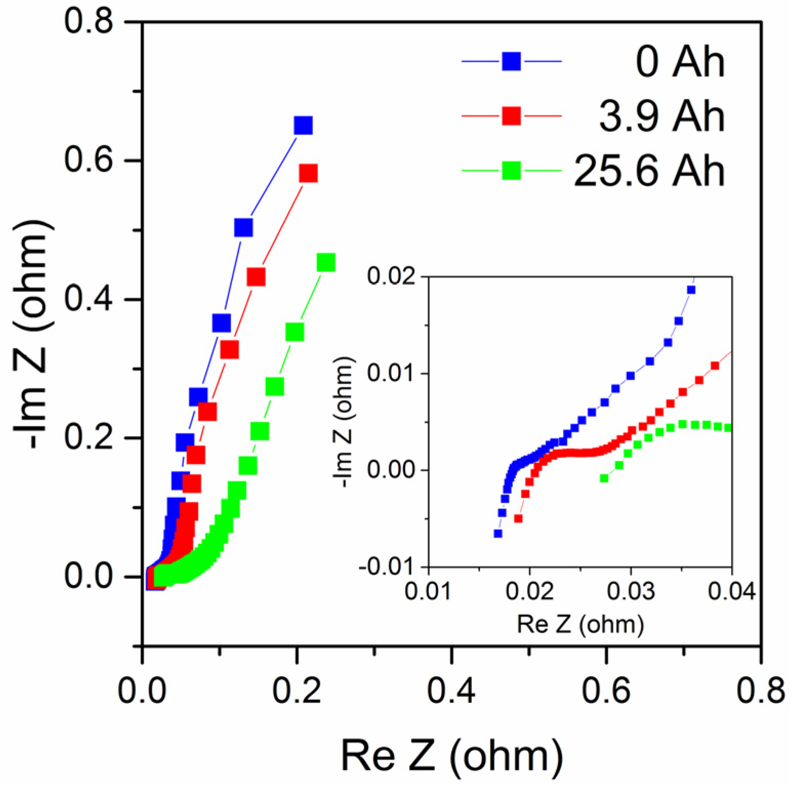
Figure 9 shows impedance measurements of the same cell during its use, at 0, 3.9 and 25.6 Ah discharge. Impedance plots of zinc–air batteries are complex but can often be described by a low-frequency part mainly related to cathode reactions, possibly also including a Warburg diffusion element, a medium-frequency part mainly related to the anode; while the high-frequency region shows an inductive response that can be due to electrode porosity, cell geometry and electrical leads [
11,
12]. The impedance plots in
Figure 9 show similar behavior but data are too limited to make an in-depth analysis in this case. Nevertheless, the results show that the series resistance (determined from the intersection with the real axis in the complex impedance plot) increased from about 18.3 mΩ to 28.2 mΩ at end of life (a 54% increase), and that the medium-frequency impedance increased with the increased discharge as expected as the anode is consumed. Also, the low-frequency part is affected, maybe partially as a consequence of the formation of zinc oxide as suggested by Schröder et al. [
13]. It can be noted that the 25.6 Ah total discharged capacity is lower than the rated capacity (48 Ah with a 1 A discharge current); however, the cell had underwent abusive tests including higher discharge currents than 1 A, prior to the final discharge procedure with a 1 A discharge current.


