Skip to Content
  • Article
  • Open Access

26 May 2026

Study on Thermal Runaway Protection Characteristics of Prismatic Lithium-Ion Battery Modules Integrating Sodium Acetate Trihydrate, Aerogel Felt and Liquid Cooling


,
,
,
,
,
,
,
,
and
1
State Key Laboratory of Maritime Technology and Safety, Wuhan University of Technology, Wuhan 430063, China
2
School of Automotive Engineering, Wuhan University of Technology, Wuhan 430070, China
3
School of Naval Architecture, Ocean and Energy Power Engineering, Wuhan University of Technology, Wuhan 430063, China
4
Research Institute of State Grid Zhejiang Electric Power Co., Ltd., Hangzhou 310006, China

Abstract

With the widespread application of lithium-ion battery energy storage stations, thermal runaway (TR) of energy storage batteries has evolved into a safety issue that cannot be overlooked. To prevent the propagation of thermal runaway, this study proposes a thermal runaway protection strategy for prismatic battery modules based on the sodium acetate trihydrate-expanded graphite (SAT-EG), aerogel felt (AEGF) and liquid cooling. The study also investigates the impact of factors such as the thickness of the SAT-EG, the thickness of the AEGF, and the area of the AEGF on the protection performance. The results show that compared with the conventional paraffin-expanded graphite (PA-EG), SAT-EG can block the propagation of thermal runaway, but the maximum temperature of adjacent batteries still approaches T2 (T2 denotes the battery thermal runaway triggering temperature). After introducing AEGF to form a sandwich structure, the maximum temperature of adjacent batteries can be effectively controlled below T1 (T1 denotes the temperature at which heat generation from battery side reactions intensifies). However, the utilization rate of SAT-EG is relatively low, and the thermal runaway trigger time of the thermal runaway battery is advanced. By reducing the AEGF area, the overall utilization rate of SAT-EG can be effectively improved, and the thermal runaway trigger time of the thermal runaway battery can be significantly delayed, gaining time for the detection and handling of thermal runaway and ensuring the safety of energy storage power stations.

1. Introduction

Lithium-ion battery energy storage systems have been widely deployed in grid-scale energy storage applications by virtue of their high energy density, fast response speed, and low economic cost [1]. Benefiting from superior energy density and long cycle life, lithium-ion batteries are also extensively adopted in electric vehicles, consumer electronics, and various energy storage systems, serving as a promising energy storage medium for power and electronic equipment [2,3,4]. With the popularization of lithium-ion batteries, relevant technologies have been steadily advancing. Based on the lithium intercalation mechanism, Theodore theoretically compared various materials and analyzed key physical and electrochemical parameters for cathode design [5]. To achieve high energy density, researchers develop new electrode materials, optimize battery structures and explore innovative electrochemical systems [6]. Nevertheless, the improvement in energy density has also brought prominent safety risks. Severe internal heat accumulation during battery operation may trigger combustion and explosion accidents, among which thermal runaway and its cascading propagation are the most critical safety hazards restricting battery application and promotion [7,8,9].
Lithium-ion batteries remain thermally stable under normal operating conditions, with heat effectively dissipated through natural cooling. However, thermal runaway can still be initiated under extreme abusive conditions [10]. Therefore, exploring the intrinsic mechanism of battery thermal runaway is essential for the development of targeted prevention and control strategies [11]. Generally, the inducements of lithium-ion battery thermal runaway are classified into three categories: mechanical abuse, electrical abuse, and thermal abuse [12]. Mechanical abuse mainly includes external collision, compression, and nail penetration, which are key evaluation indicators of battery safety. Such mechanical damage may rupture the battery separator and further induce internal short circuits, thereby causing battery failure [13]. Chai et al. established a regression model to characterize battery dynamic responses under mechanical abuse, providing a feasible evaluation method for battery safety [14]. They further proposed multi-field coupling modeling and safety assessment techniques, which offer reliable theoretical support for predicting and analyzing the mechanical safety performance of lithium-ion batteries [15]. Xiao et al. systematically reviewed the advantages, limitations, and evolutionary progress of existing battery modeling methods and prospected the future development trends of this research field [16].
Electrical abuse primarily covers overcharging, over-discharging, and external short circuits. Gui et al. revealed the safety degradation mechanism of sodium-ion batteries under abnormal electrical conditions, providing a reference for battery structural optimization and safety evaluation [17]. Xu et al. investigated the influences of operating parameters (including heat source location, charging rate, and discharging rate) on the internal state and thermal runaway behaviors of lithium-ion batteries [18]. Liu et al. further verified that elevated charging rates can aggravate thermal runaway reactions and significantly increase battery safety risks [19]. In terms of thermal abuse, typical triggers include heat dissipation failure and excessive ambient temperature [20,21]. Kwak et al. explored the thermal runaway evolution characteristics of LiFePO4 batteries and constructed a multi-physics coupling model to guarantee battery thermal stability [22]. Su et al. comparatively analyzed gas generation behaviors during thermal runaway under different abusive conditions and found that thermal abuse induces higher and more fluctuating gas concentrations compared with electrical abuse [23]. When the battery temperature exceeds the critical threshold, irreversible thermal runaway occurs, leading to a rapid temperature rise above 600 °C and eventually triggering battery ignition and large-scale fire accidents [24].
To mitigate thermal runaway risks and improve battery thermal safety, various passive and active battery thermal management systems (BTMSs) have been developed. Phase change material (PCM)-based passive BTMSs have gained widespread attention due to their low cost and excellent temperature uniformity [25]. Previous studies have analyzed the structural characteristics and heat generation/transfer mechanisms of lithium-ion batteries, summarized the research progress of cooling system models, and explored the application potential of PCM-based hybrid thermal management systems [26]. However, most organic PCMs suffer from high flammability, which may exacerbate thermal runaway propagation and aggravate battery safety hazards [27]. Accordingly, inorganic PCMs with high latent heat and non-flammability have become a research hotspot for high-safety BTMSs [28]. Cao et al. proposed a passive BTMS based on sodium acetate trihydrate-ethylene glycol (SAT-EG) composite PCM and verified the two-stage heat storage performance of SAT through model establishment and experimental validation [29]. Liu et al. investigated the suppression effect of aerogel felts with different thicknesses on thermal runaway propagation and confirmed that thicker aerogel felts can effectively delay the thermal runaway process [30]. Nasar et al. compared the cooling performance of unilateral and bilateral parallel cooling structures, and the results showed that bilateral cooling can reduce battery peak temperature and temperature gradient, thus improving battery operating performance and service life [31]. Sen et al. developed a novel PCM-liquid cooling hybrid system, which achieves better cooling efficiency and temperature uniformity than traditional single liquid cooling strategies [32]. In addition, Xiao et al. designed an active-passive composite cooling system integrating PCM and liquid cooling, and systematically analyzed the key factors affecting thermal runaway propagation in battery modules [33]. Wilke et al. adopted a lightweight and low-cost paraffin-expanded graphite composite PCM to conduct nail penetration tests on small electric vehicle battery packs and validated the effectiveness of this composite PCM in inhibiting thermal runaway propagation [34].
Sodium acetate trihydrate (SAT) shows great potential in mitigating battery thermal runaway, but its low thermal conductivity limits latent heat utilization. Combining with expanded graphite enhances its thermal conductivity and heat absorption [35]. Aerogel felt blocks heat propagation via good thermal insulation, while liquid cooling plates dissipate heat quickly to avoid local overheating [36].
Energy storage power stations are key targets for thermal runaway protection, yet their protection is constrained by limited installation space and the need to prevent large-scale fire accidents, which imposes stricter requirements on their thermal safety performance. To address these challenges, this study proposes an integrated protection strategy combining sodium acetate trihydrate-expanded graphite (SAT-EG), aerogel felt (AEGF), and a liquid cooling system. Compared with existing research on the coupling of phase change materials, aerogels and liquid cooling, this work firstly constructs a sandwich interlayer structure composed of SAT-EG and AEGF. By optimizing the coverage area of AEGF, the internal heat transfer characteristics of the battery pack are regulated. This approach fully utilizes the latent heat advantage of SAT-EG and the thermal insulation performance of AEGF. The temperature of batteries adjacent to the thermal runaway battery is controlled below T1, while the triggering time of thermal runaway is prolonged as much as possible. Consequently, thermal runaway propagation is effectively suppressed, providing reliable safety guarantees for the operation of energy storage power stations.

2. Numerical Model

2.1. Geometric Model

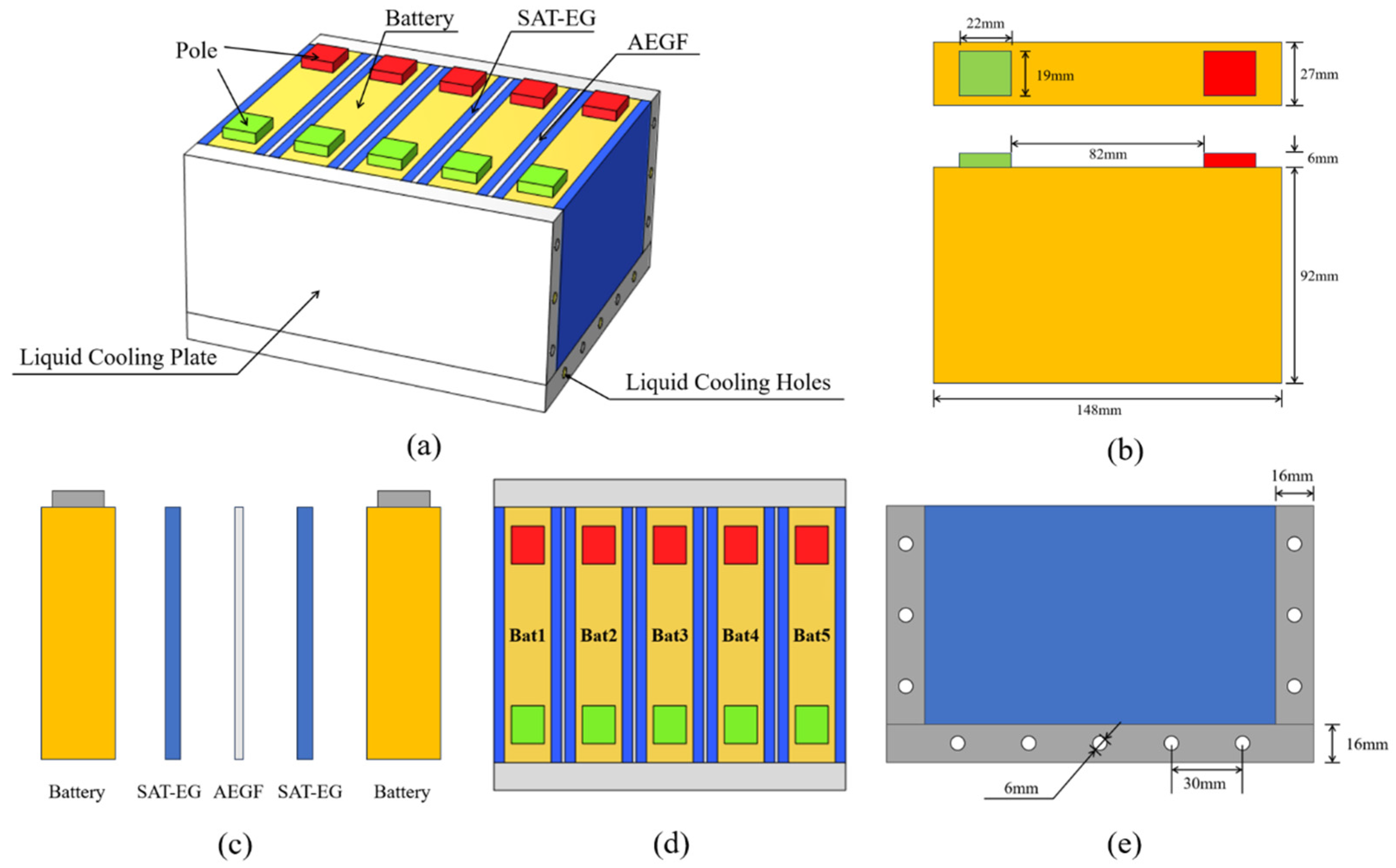
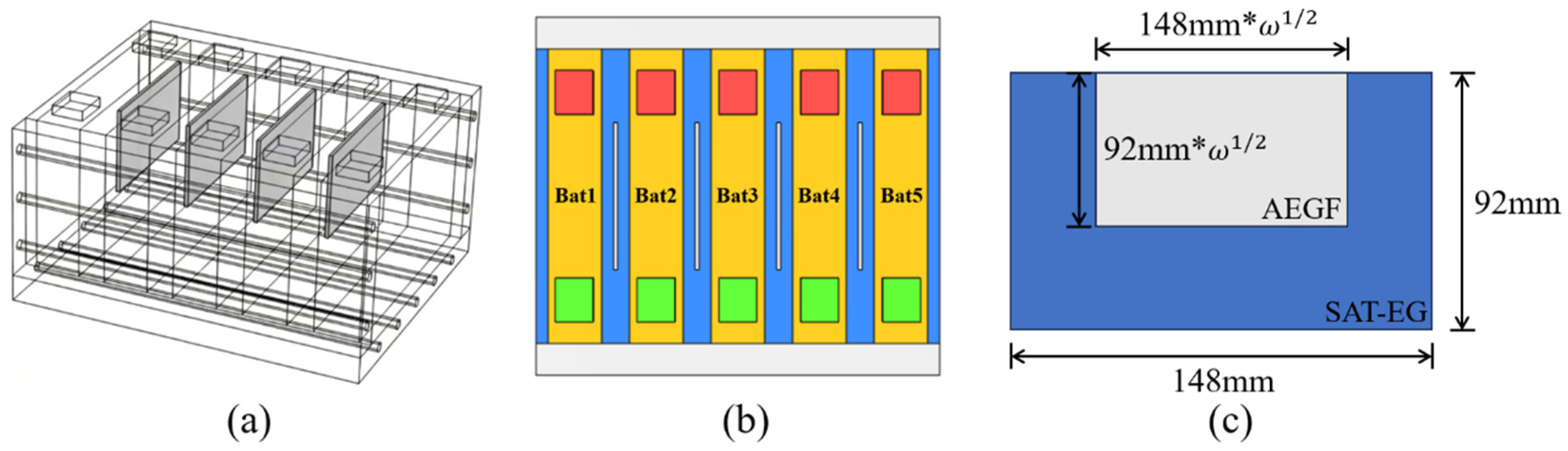
In this study, a battery module consisting of five batteries is established. A sandwich structure composed of SAT-EG and AEGF is arranged between two adjacent batteries, with its overall thickness consistent with the battery spacing, and liquid cooling plates are installed on the side and bottom of the battery module. The width, depth, and height of the battery are 148 mm, 27 mm, and 92 mm, respectively; the corresponding dimensions of the electrode are 22 mm, 19 mm, and 6 mm. Two types of sandwich structures are designed in this work. The first is an integral sandwich structure formed by full-size AEGF and SAT-EG, where the AEGF completely isolates the SAT-EG on both sides, and the thickness of AEGF is set as a variable. The second structure adopts partially arranged AEGF combined with SAT-EG. In this case, the thickness of the partial AEGF is fixed at 2 mm, and its aspect ratio is consistent with that of the battery, which is 148:92. The area ratio is defined as ω , representing the ratio of the reduced AEGF area to the area of fully covered AEGF. After determining the thickness and area of the AEGF in the above sandwich structure, the remaining space is filled with SAT-EG. Parallel liquid cooling pipes are arranged inside the liquid cooling plate, with a radius of 3 mm and a spacing of 30 mm between adjacent pipes. The detailed parameters of the first structure are presented in Figure 1.
Figure 1. Geometric model and parameters of the battery module: (a) battery module composition; (b) single battery dimensions; (c) sandwich structure; (d) battery numbering; (e) channel dimensions.
Common phase change materials used in battery module thermal management include paraffin-expanded graphite (PA-EG) composite phase change materials [34], but their overall latent heat is relatively low, whereas SAT-EG exhibits a higher comprehensive latent heat. In this study, nickel–cobalt–manganese prismatic lithium-ion batteries are adopted, and the composite phase change material selected is SAT-EG [35], in which the mass fraction of SAT is 80%, and that of EG is 20%. The type of aerogel felt is nano-AEGF [36], the coolant is water, and the flow direction of the coolant in the liquid cooling tubes is staggered flow. The parameters of lithium-ion batteries, PA-EG, SAT-EG, AEGF, and the liquid cooling system adopted in this study are listed in Table 1, Table 2, Table 3, Table 4 and Table 5.
Table 1. Material properties of battery.
Table 2. Material properties of PA-EG.
Table 3. Material properties of SAT-EG.
Table 4. Material properties of AEGF.
Table 5. Material properties of liquid cooling system.
Before establishing the simulation model, the lithium-ion battery is modeled under the following assumptions: (1) The battery material is homogeneous, with a constant density throughout the entire process; (2) convection and radiation heat transfer inside the battery are neglected due to the limited mobility of the electrolyte; (3) specific heat capacity and thermal conductivity are treated as constant values; (4) battery swelling is disregarded; (5) it is assumed that the battery and its variations are identical; (6) each battery in the module is modeled as a thermally independent individual battery.

2.2. Mathematical Model of Battery

2.2.1. Battery Thermal Runaway Heat Generation Model

In practical scenarios, due to varying abuse conditions, the heat generation of batteries exhibits significant differences, and the timing of intensified side reactions and the occurrence of internal short circuits also vary notably. Therefore, this paper simulates the triggering process of thermal runaway behavior in the battery modules under different heat generation conditions by setting an initial abnormal heat generation rate.
The heat generated during lithium-ion battery thermal runaway mainly originates from internal chemical reactions, and the chemical reaction rate d c r x n / d τ varies with temperature T . Before the initial temperature reaches T 1 = 99   ° C , the heat generated by side reactions can be neglected. When T 1 < T T 2 = 132.7   ° C , the temperature rise rate can be fitted by an empirical equation, and the internal side reactions inside the battery are intensified at this stage. Once the temperature exceeds T > T 2 , battery thermal runaway is triggered, accompanied by massive heat release. The empirical equation is expressed as follows [35]:
d c r x n d τ = 0 T T 1 M C p Δ H A T T Ref b 0 c r x n 1 ,   T 1 < T T 2 C 0 c r x n 1 ,   T > T 2
where M and C p represent the mass and specific heat capacity of the battery, respectively. Δ H = 582.9   k J is the total energy released by the cell during thermal runaway. A = 0.92   s 1 is the pre-exponential factor, whose physical meaning is the reaction rate during the side reaction heat generation stage ( T 1 < T T 2 ). In the slow self-heating stage before thermal runaway is triggered, a larger value of A leads to a faster initial reaction rate, a quicker temperature rise, and an easier trigger of thermal runaway. b = 28.5 is the reaction order, a dimensionless quantity that characterizes the sensitivity of the reaction rate to temperature during the side reaction heat generation stage. A larger value indicates greater temperature sensitivity of the reaction rate; a small temperature increase causes a sharp rise in the reaction rate, reflecting the strong nonlinearity and positive feedback self-acceleration characteristics of lithium-ion battery thermal runaway. The constant C = 12   s 1 denotes the constant reaction rate after thermal runaway is triggered. The value of C is much larger than that of the pre-exponential factor A , signifying the abrupt increase in reaction rate and instantaneous release of a large amount of heat upon thermal runaway initiation, which corresponds to the rapid temperature surge and deflagration phenomenon during lithium-ion battery thermal runaway [35].
During thermal runaway, the temperature rise rate of the battery, d T / d τ , can be determined by the following relationship:
Δ H d c r x n d τ = M C p d T d τ

2.2.2. Battery Heat Transfer Model

Part of the heat generated by the battery is absorbed by the battery itself, while the remainder is transferred to the surroundings through conduction, convection, and radiation. In engineering calculations, heat radiation and convection, which account for relatively small proportions, are typically neglected. Consequently, the primary mode of heat transfer in batteries is thermal conduction, a process governed by Fourier’s law. The governing equation for thermal conduction is as follows:
ρ C p T t = λ x 2 T x 2 + λ y 2 T y 2 + λ z 2 T z 2 + Q V
where ρ represents density (kg·m−3); C p denotes the specific heat capacity at constant pressure (J/(kg·K)); λ x , λ y , and λ z are the thermal conductivities (W/(m·K)) in the x-, y-, and z-axis directions, respectively; and Q V is the volumetric heat generation rate (W/m3). This equation quantifies anisotropic heat transfer through a spatial thermal conductivity tensor.

2.3. Mathematical Model of SAT Phase Change and Thermal Decomposition

When the temperature of the hydrated salt composite phase change material (CPCM) increases, it undergoes distinct heat storage stages. As the CPCM temperature rises from the initial temperature (25 °C) to the phase change temperature (58 °C), heat is absorbed by the material in the form of sensible heat. During the phase change process, a substantial amount of heat is stored in the CPCM as latent heat. After the phase change is complete, heat is once again absorbed in the form of sensible heat. When the temperature exceeds 106 °C, the CPCM undergoes chemical decomposition, during which it absorbs a significant amount of heat through chemical reactions. For the sensible and latent heat of the CPCM, the apparent heat capacity method is employed, expressed as:
ρ C P C M C p , e f f T t = · k C P C M T
where ρ C P C M , C p , e f f and k C P C M represent the density, effective specific heat capacity, and thermal conductivity of the CPCM, respectively. Among them, the temperature dependence of C p , e f f is given as follows:
C p , eff = C p , s T T s 1 β C p , s + β C p , l + L CPCM T l T s T s < T < T l C p , l T l T
where β represents the liquid fraction of the CPCM, and its temperature-dependent expression is given as follows:
β = 0 T T s T CPCM T s T l T s T s < T < T l 1 T l T
where C p , s and C p , l represent the specific heat capacities of the CPCM in its solid and liquid states, respectively. L C P C M denotes the phase change enthalpy of the CPCM, while T s and T l are the critical temperatures at which the CPCM is about to undergo phase change from solid and has completely transformed into liquid, respectively. T C P C M is the temperature of the CPCM.
During thermochemical heat storage, the heat absorbed per unit time can be calculated as the product of the reaction heat and the reaction rate, with the expression given as follows:
q ˙ = H d e c · r
where q ˙ ,   H d e c and r represent the reaction heat per unit time, the chemical reaction heat of the CPCM, and the reaction rate, respectively.
As the reaction progresses, the concentration of SAT ( C A ) gradually decreases, and r is calculated as the derivative of C A with respect to time, with the expression given as follows:
r = d C A d t = d C A 0 1 α d t = C A 0 d α d t = C A 0 d α d T d T d t = C A 0 β d α d T
where C A 0 represents the initial concentration of SAT, α denotes the extent of the chemical reaction, and β is the temperature rise rate of the CPCM. Among them, d α / d T can be calculated according to the Arrhenius equation as follows:
d α d T = A e x p E a R T G α
where A = 7.841 × 10 16   s 1 represents the pre-exponential factor, and E a = 1.4767 × 10 5   J / m o l denotes the activation energy [29].
In COMSOL Multiphysics (version 6.2), the first-stage heat absorption of SAT-EG is introduced via the equivalent heat capacity term, while the second-stage heat absorption is incorporated as a source term. In the simulation, SAT-EG is assumed to exhibit the following characteristics: (1) Each phase maintains constant physical properties; (2) the liquid phase is considered incompressible; (3) the material is homogeneous and possesses isotropic thermal conductivity. AEGF is assumed to demonstrate the following characteristics: (1) it maintains constant physical properties; (2) the material is homogeneous and has isotropic thermal conductivity.

2.4. Mathematical Model of Liquid Cooling

Convective heat transfer achieves thermal exchange through the flow of the coolant. The following assumptions are made regarding the heat transfer process of the liquid inside the cooling tube: (1) the liquid flow is steady and incompressible; (2) the liquid working medium (water) is a Newtonian fluid; (3) the thermophysical properties of the fluid are constant; (4) the effects of gravity, other body forces, thermal radiation, and the coolant inlet are neglected.
The mass, momentum, and energy equations are as follows:
ρ w t + · ρ w v = 0
t ρ w v + · ρ w v v = p + μ v
t ρ w C p , w T w + · ρ w C p , w v T w = k w T w
where ρ w represents the density of water, v is the velocity vector of water, while C p , w ,   k w and p denote the specific heat capacity, thermal conductivity, and static pressure of the cooling fluid, respectively.

2.5. Boundary and Initial Conditions

COMSOL Multiphysics is utilized to configure the boundary and interface conditions for the battery module. The boundary conditions at the interfaces between the battery and CPCM, battery and Al plate, CPCM and Al plate, as well as Al plate and cooling tube, are set as follows:
k b T b n b = k C P C M T C P C M n C P C M
k b T b n b = k A l T A l n A l
k C P C M T C P C M n C P C M = k A l T A l n A l
where n represents the outward normal direction on the outer surface of each component, and T / n denotes the temperature gradient of each component along the normal direction. k b , k C P C M and k A l are the thermal conductivities of the battery, CPCM, and Al plate, respectively. T b , T C P C M and T A l represent the temperatures of the battery, CPCM, and Al plate, respectively.
In a non-adiabatic environment, the primary consideration is the natural convective heat transfer process between the lithium-ion battery and the external environment. According to Newton’s law of cooling, this heat transfer process can be expressed as:
q = h T b s T a m b
where q is the heat flux density (W/m2), h is the convective heat transfer coefficient at the interface between the battery and the external environment (W/(m2·K)), T b s is the surface temperature of the battery (K), and T a m b is the ambient temperature (K).

2.6. Model Validation and Grid Independence Verification

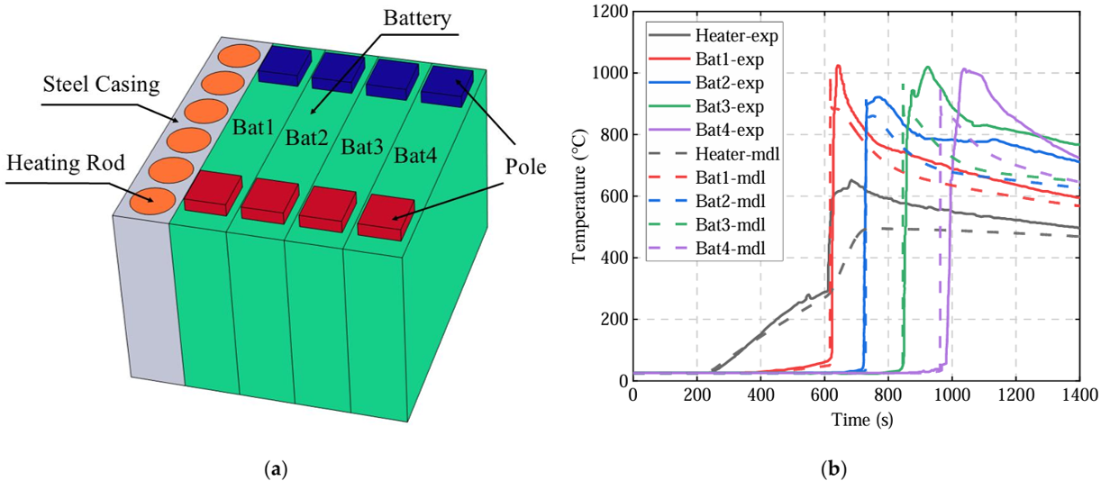
The model validation has been demonstrated in previous work [37] as shown in Figure 2. In previous work, the experimental conditions reported in Reference [35] were reproduced, and a thermal runaway propagation verification model was established as illustrated below to validate the accuracy of the mathematical model describing heat generation and heat transfer during battery thermal runaway. The heating plate has a total heating power of 1700 W and consists of six heating rods. Temperature measuring points were arranged on the heater surface and at the center of the four batteries, consistent with the placement of temperature sensors in the experiment. By comparing the simulation results of the five temperature measuring points with the experimental data, the comparison curves shown in the figure were obtained. In the experiment, the thermal runaway moments of the four batteries were 624 s, 724 s, 850 s, and 982 s, respectively. In the simulation, the corresponding thermal runaway moments were 617 s, 728 s, 845 s, and 962 s. The results indicate that the established model achieves an accuracy of over 95% in predicting the thermal runaway triggering time.
Figure 2. Validation of the lithium-ion battery TR model [37]: (a) geometric model; (b) comparison of simulation values and experimental values.
The verification of the two-stage latent heat mathematical model for SAT was conducted by establishing a corresponding simulation model based on the experimental conditions in Reference [29]. The results show that under the SAT-EG wrapped scheme, the temperature curve at point Tb is consistently lower than that at Ta, indicating that heat generated by the heating rod is absorbed by the latent heat of the SAT-EG layer during heat transfer. Meanwhile, the temperature curve of Tb exhibits two distinct plateau stages, which correspond to the latent heat release during the phase transition and decomposition reaction of the SAT-EG material, respectively. The relative average errors between the simulated and experimental values of Ta and Tb are 11% and 8%, respectively. The simulation results are highly consistent with the theoretical trends, which verifies the effectiveness and accuracy of the SAT-EG latent heat model.
After completing the geometric model construction and parameter setting, it is necessary to conduct mesh generation for the model. In this paper, free tetrahedral meshing is adopted. In the numerical simulation process, the mesh density directly affects the computational speed and accuracy. Relatively coarse meshing yields fast calculation but insufficient accuracy, whereas overly fine meshing prolongs the computation time. Therefore, selecting appropriate meshing can shorten the calculation time and save computational cost while ensuring accuracy.
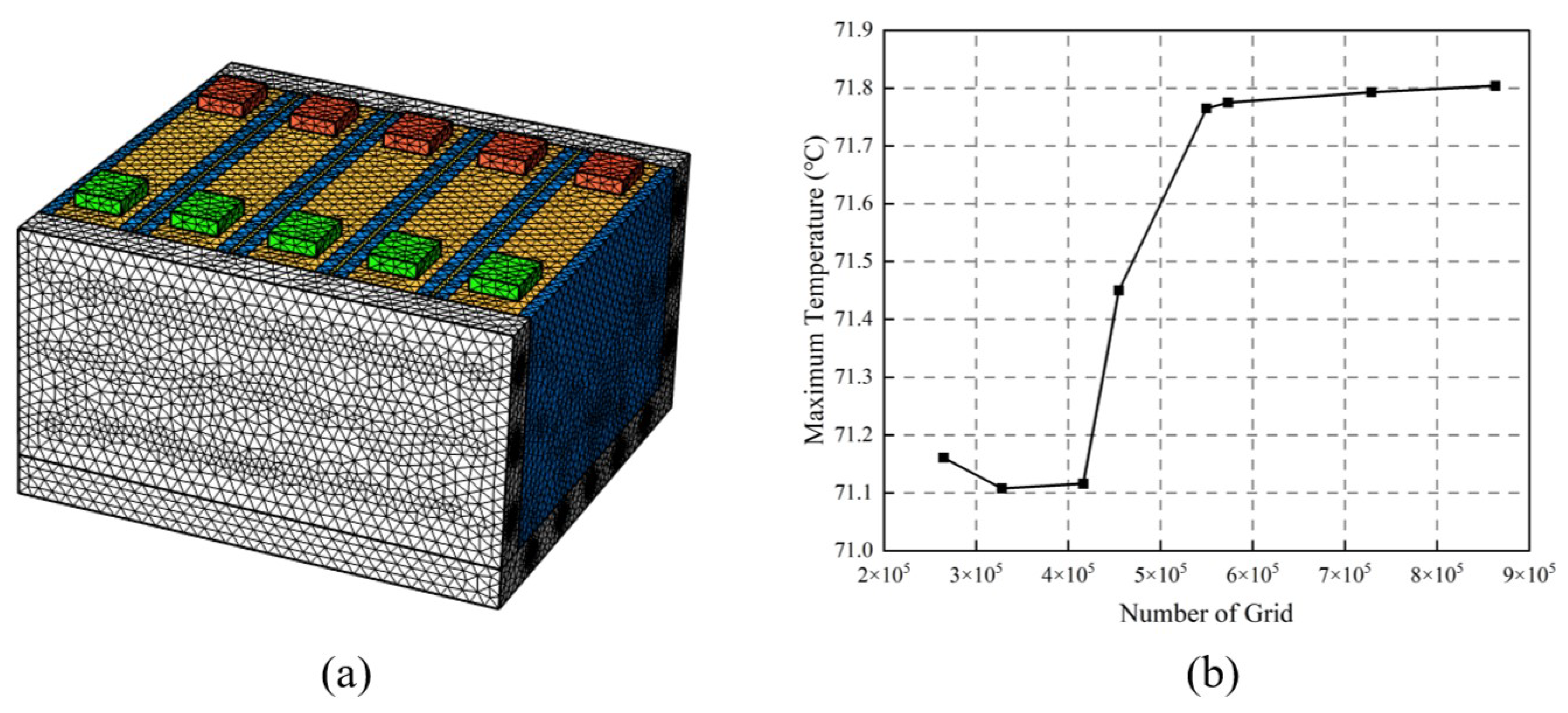
In this section, the battery spacing is set to 12 mm, with the SAT-EG thickness on both sides being 5 mm and the AEGF thickness being 2 mm. The initial heat generation rate of the abnormally heating battery is set to 200 W, and the simulation duration is 800 s. By adjusting the global element size and manually defining local mesh refinement, eight sets of tetrahedral meshes with different element counts are finally generated: 264,644, 327,914, 416,290, 454,790, 549,772, 573,288, 728,787, and 863,366. Figure 3a shows the schematic diagram of the mesh with 573,288 tetrahedral elements. After simulation, the maximum temperatures of the battery module under the eight different mesh schemes are shown in Figure 3b.
Figure 3. Model meshing (a) and grid independence verification (b).
In the figure, the abscissa represents the number of mesh elements, and the ordinate represents the maximum temperature of the battery module in ℃. The maximum temperature of the battery module is 71.161 °C at 264,644 mesh elements, 71.108 °C at 327,914 elements, 71.116 °C at 416,290 elements, 71.450 °C at 454,790 elements, and 71.765 °C at 549,772 elements.
It can be seen that when the number of meshes is below 549,772, the maximum temperature of the battery module is sensitive to the variation in mesh count, leading to low computational accuracy and large simulation errors. When the number of meshes is increased to 573,288, 728,787, and 863,366, the maximum temperatures of the battery module reach 71.775 °C, 71.793 °C, and 71.804 °C, respectively, and the results tend to be stable, indicating that further increasing the number of meshes has little effect on the calculation results. To avoid accidental errors, the mesh scheme with 573,288 elements is adopted for subsequent calculations.

3. Results and Discussion

3.1. Comparison of Protective Effects Between PA-EG and SAT-EG

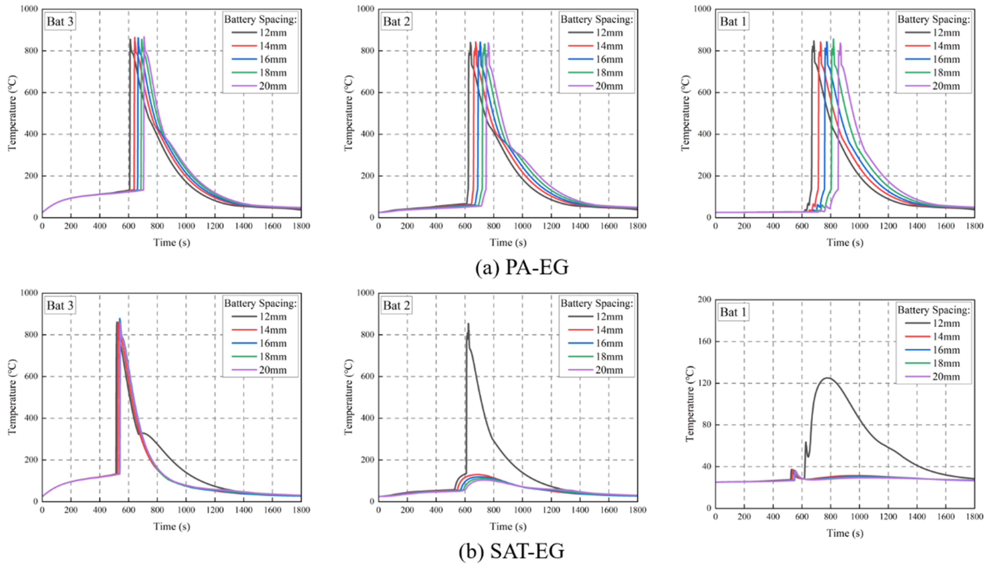
At high abnormal heat generation rates, battery modules face the risk of thermal runaway propagation leading to large-scale fires. Common phase change materials, such as paraffin-graphite (PA-EG) and sodium acetate trihydrate-expanded graphite (SAT-EG), are often used in battery module thermal management. In this paper, Bat3 is set as the initial abnormal heat-generating battery with an abnormal heat generation rate of 500 W, and the battery spacing ranges from 12 mm to 20 mm. This section investigates the differences in the protective effects of PA-EG and SAT-EG combined with liquid cooling on thermal runaway propagation in battery modules under the above conditions. The comparison of protective effects between PA-EG and SAT-EG at different battery spacings is shown in Figure 4.
Figure 4. Comparison of protective effects between PA-EG (a) and SAT-EG (b) at different battery spacings.
As can be seen from Table 6, when protected by PA-EG, even at a thickness of 20 mm, it still fails to block the thermal runaway propagation of Bat3. The generated heat spreads to Bat2, Bat4 and Bat1, Bat5. The maximum temperatures of the batteries adjacent to the thermal runaway battery all exceed T2, triggering large-scale thermal runaway. When protected by SAT-EG, at a thickness of 12 mm, thermal runaway propagates to Bat2 and Bat4 but not to Bat1 and Bat5. At this time, the maximum temperatures of Bat1 and Bat5 are below T2 but above T1. When the thickness of SAT-EG reaches 14 mm or more, thermal runaway is blocked. The maximum temperatures of Bat2 and Bat4 are below T2 but above T1, while the maximum temperatures of Bat1 and Bat5 are below 40 °C. When the thickness of SAT-EG is increased to 20 mm, the maximum temperatures of Bat2 and Bat4 remain above T1, accompanied by intense internal side reactions and a high risk of thermal runaway and fire. In addition, under the protection of SAT-EG and with a battery spacing of 14–20 mm, the thermal runaway trigger times of Bat3 are relatively close, all above 500 s, specifically 523 s, 535 s, 539 s and 555 s, respectively.
Table 6. Maximum temperatures of Bat1 and Bat2 at different battery spacings.
The above differences between the two protection conditions arise because SAT-EG possesses two-stage latent heat and delivers a higher overall latent heat capacity compared with PA-EG, while its thermal conductivity is lower than that of PA-EG. Therefore, at different battery spacings, the SAT-EG protection structure can block thermal runaway propagation once reaching a certain thickness, and the thermal runaway triggering time of Battery 3 remains relatively stable. In contrast, the PA-EG protection scheme still fails to prevent the thermal runaway propagation of Battery 3 even at relatively large battery spacing.

3.2. Effect of AEGF Thickness on Thermal Runaway Protection of Battery Modules

3.2.1. Effect of AEGF Thickness on the Temperature of Bat2

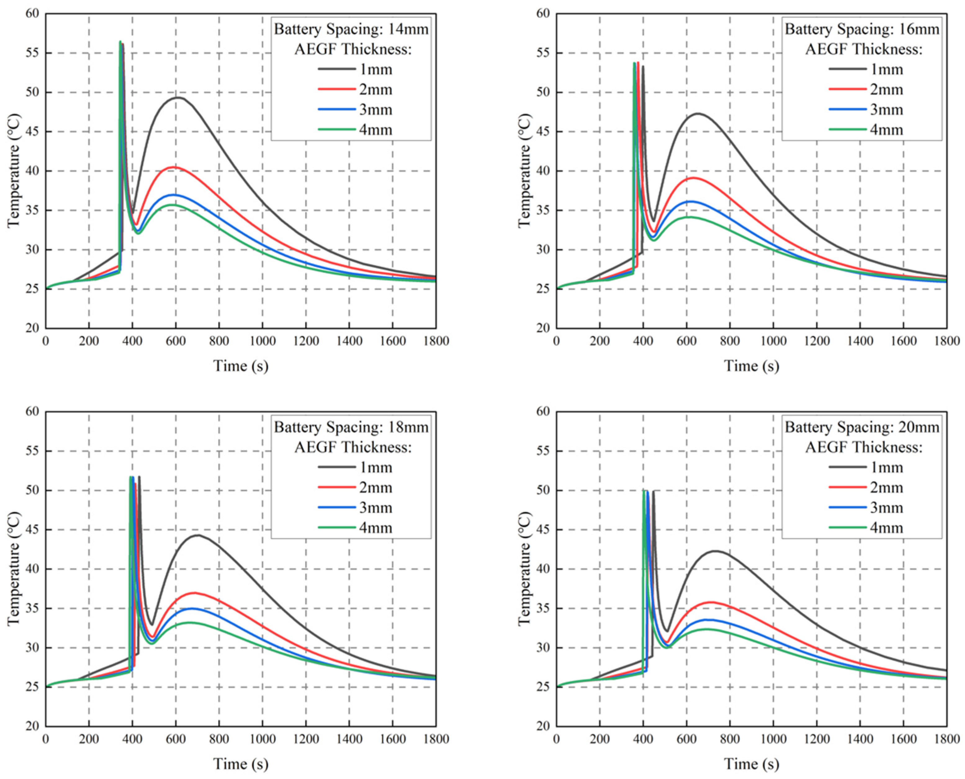
As can be seen from the previous section, it is difficult to control the maximum temperature of Bat2 in the battery module below T1 by using SAT-EG alone, and the side reactions inside the battery are relatively intense. To weaken the internal side reactions and reduce the risk of thermal runaway and fire, in this section, AEGF with low thermal conductivity is combined with SAT-EG to form a sandwich structure, whose geometric model is shown in Figure 1c. The protective effect of this structure on the thermal runaway of the battery module is investigated. AEGF with a thickness of 1–4 mm is selected in this section, and the discussion is carried out based on the thickness of the AEGF layer and the battery spacing.
Figure 5 shows the temperature–time curves of Bat2 at different AEGF thicknesses and various battery spacings. It can be seen from the figure that at the same battery spacing, the control effect of the sandwich structure on the maximum temperature of Bat2 gradually improves with the increase in AEGF thickness, while the downward trend of the maximum temperature of Bat2 gradually weakens. When the thickness of AEGF increases from 1 mm to 4 mm, the average decreases in the maximum temperature of Bat2 for each 1 mm increment are 7.72 °C, 2.68 °C, and 1.56 °C, respectively. Under this protection strategy, it is necessary to minimize the maximum temperature of Bat2 while taking the strength of AEGF into account. Therefore, it is appropriate to select AEGF with a thickness of 2 mm.
Figure 5. Temperature–time curves of Bat2 at different AEGF thicknesses and various battery spacings.
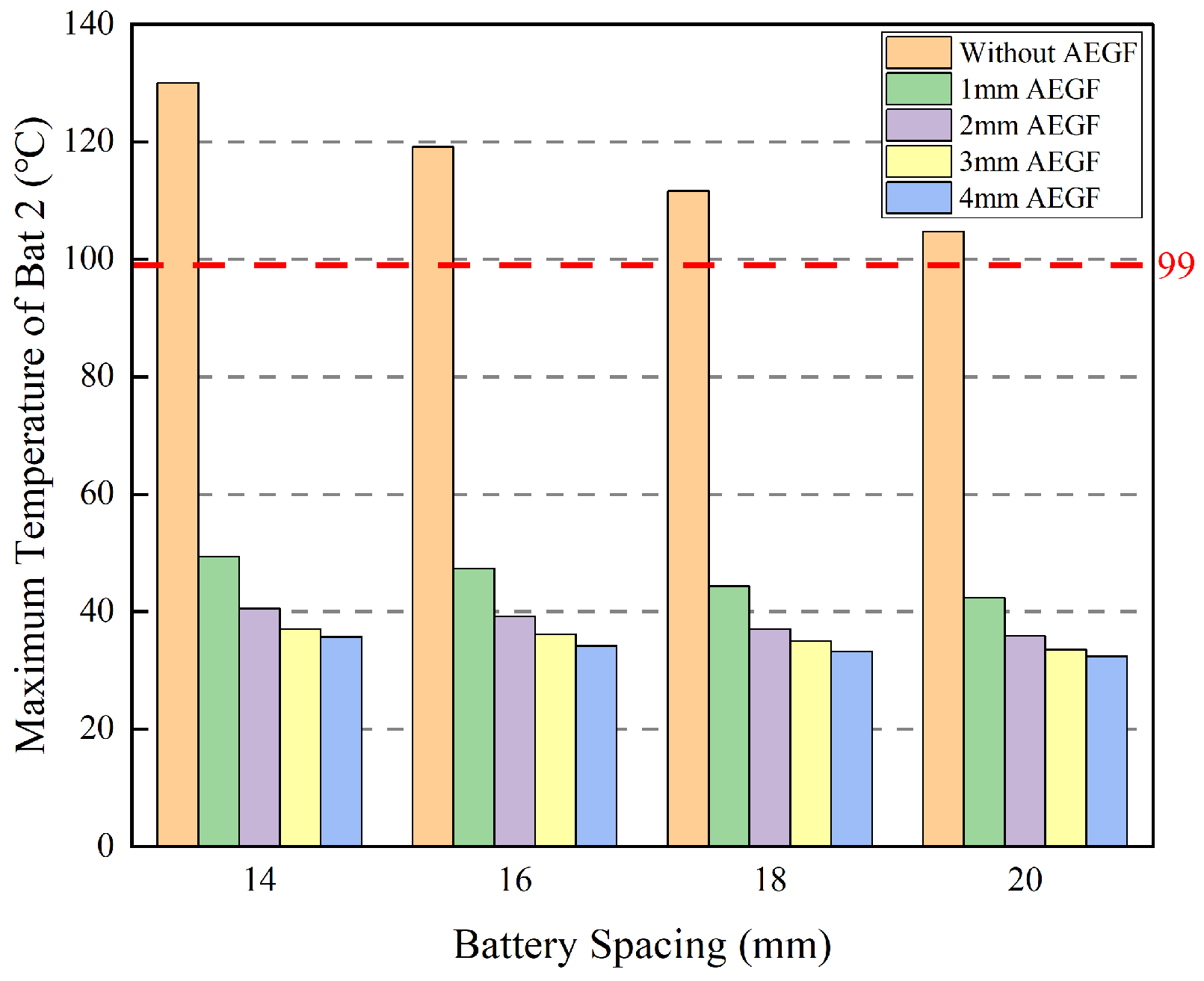
As shown in Figure 6, without the sandwich structure containing AEGF, the maximum temperature of Bat2 exceeds T1 under all four battery spacing conditions. After adopting this structure, its maximum temperature can be kept below T1 at different battery spacings and AEGF thicknesses, and it gradually decreases with the increase in AEGF thickness. It indicates that the structure presents a remarkable effect on suppressing the maximum temperature of Bat2.
Figure 6. Maximum temperature of Bat2 at different AEGF thicknesses and various battery spacings.
In the original structure, heat generated by thermal runaway propagates to adjacent batteries merely through SAT-EG. After the introduction of AEGF, its thermal conductivity is much lower than that of SAT-EG, which greatly blocks the massive heat generated by thermal runaway and prevents rapid heat transfer to adjacent batteries. The accumulated heat is eventually dissipated via the liquid cooling system and natural convection, maintaining a relatively low temperature of the batteries adjacent to the thermal runaway battery.
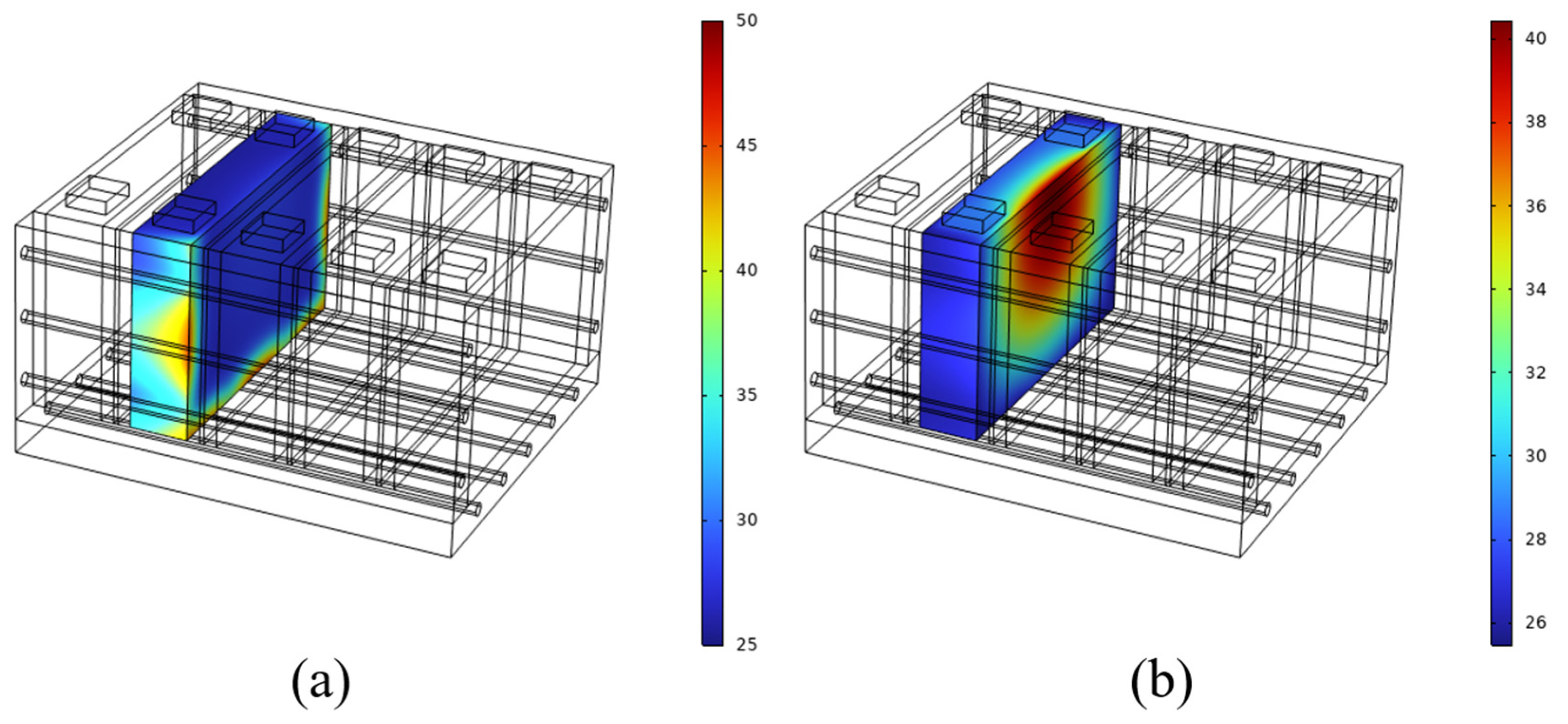
The temperature–time curves of Bat2 in Figure 4 mentioned above show two peaks. The reason is that the thermal conductivity of the liquid cooling plate is much higher than that of the sandwich structure composed of SAT-EG and AEGF. When thermal runaway occurs in Bat3, a large amount of heat generated is rapidly conducted through the liquid cooling plate to the side surface of Bat2, causing the temperature on the side to rise to a peak first. Subsequently, the liquid cooling system takes effect to remove this part of the heat, resulting in a rapid temperature drop. The heat is then transferred through the sandwich structure to the front surface of Bat2, eventually forming the second peak temperature. As shown in Figure 7 below, near the first peak, the three surfaces of Bat2 in contact with the liquid cooling plate exhibit relatively high temperatures, whereas near the second peak, the surface of Bat2 in contact with the phase change material shows a higher temperature. Since the heat causing the first peak is quickly removed by liquid cooling, this paper mainly focuses on the second peak temperature of Bat2.
Figure 7. Contour plots of the first (a) and second (b) peak temperatures of Bat2.

3.2.2. Effect of AEGF Thickness on Thermal Runaway Time of Bat3

After introducing the sandwich structure composed of AEGF and SAT-EG, the latent heat utilization rate of SAT-EG will change, which in turn alters the thermal runaway trigger time of the thermal runaway battery. Therefore, the influence of this structure on the thermal runaway trigger time of the thermal runaway battery should also be considered.
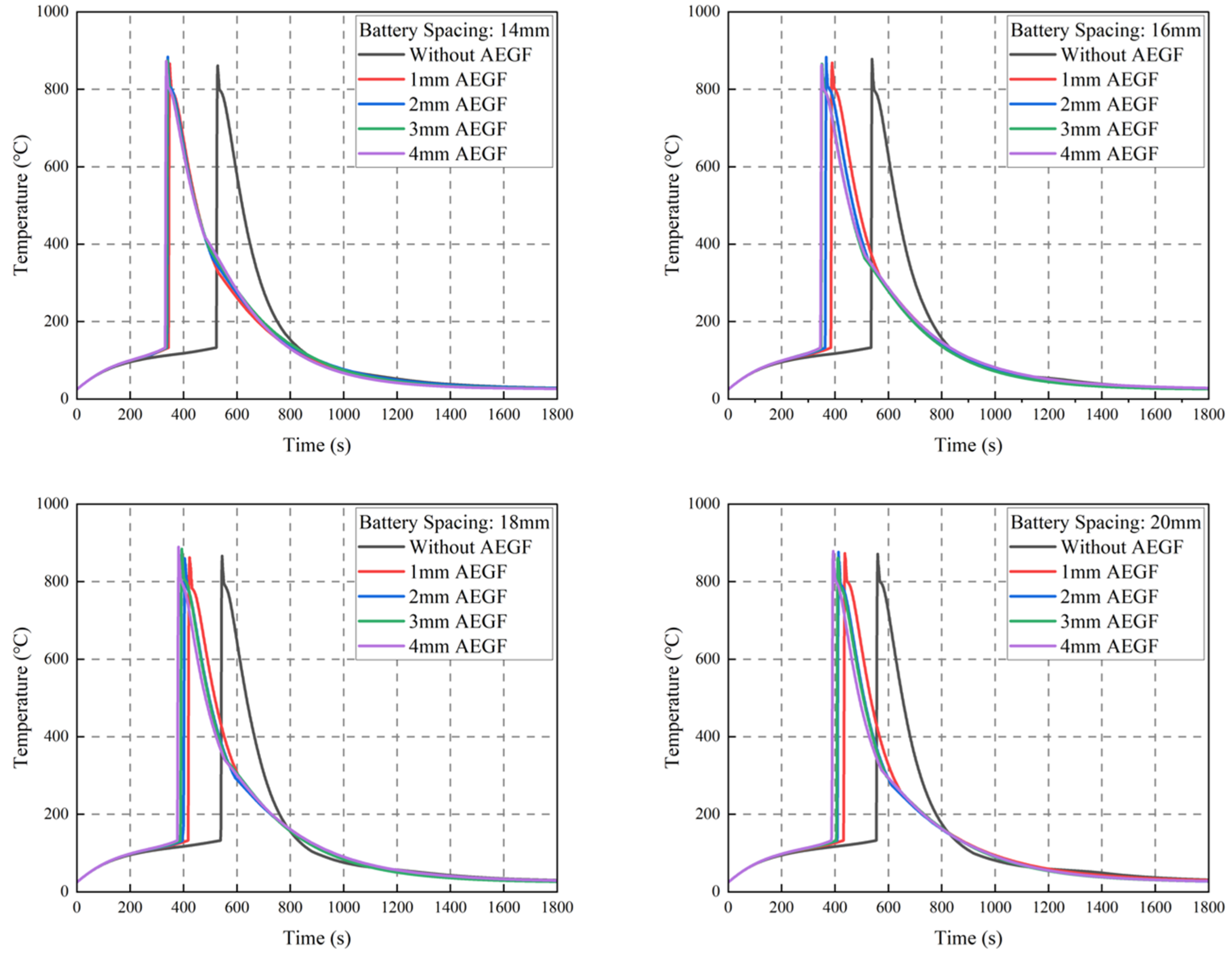
As shown in Figure 8, the thermal runaway trigger time of Bat3 is advanced after AEGF is added to form a sandwich structure. This is because AEGF possesses a low thermal conductivity, which confines the heat generated by thermal runaway to one side of the sandwich structure and prevents rapid heat transfer to the adjacent battery, thereby advancing the thermal runaway triggering time of Bat3. The thermal runaway times of Bat3 at different AEGF thicknesses and various battery spacings are presented in Table 7. At battery spacings ranging from 14 mm to 20 mm, the thermal runaway time of Bat3 is advanced by 180 s, 151 s, 122 s and 123 s, respectively, when the AEGF thickness is 1 mm; by 186 s, 172 s, 144 s and 147 s, respectively, at 2 mm; by 188 s, 188 s, 151 s and 150 s, respectively, at 3 mm; and by 192 s, 190 s, 163 s and 168 s, respectively, at 4 mm.
Figure 8. Temperature–time curves of Bat3 at different AEGF thicknesses and various battery spacings.
Table 7. Thermal runaway time of Bat3 at different AEGF thicknesses and various battery spacings.
At the same battery spacing, the thicker the AEGF in the sandwich structure, the thinner the corresponding SAT-EG layer and the less SAT-EG that contributes to latent heat absorption. Consequently, the thermal runaway trigger time of Bat3 is advanced as the AEGF thickness increases. Under the same AEGF thickness, a larger battery spacing results in a thicker SAT-EG layer within the sandwich structure and more SAT-EG available for latent heat release, so the thermal runaway trigger time of Bat3 is prolonged with increasing battery spacing.
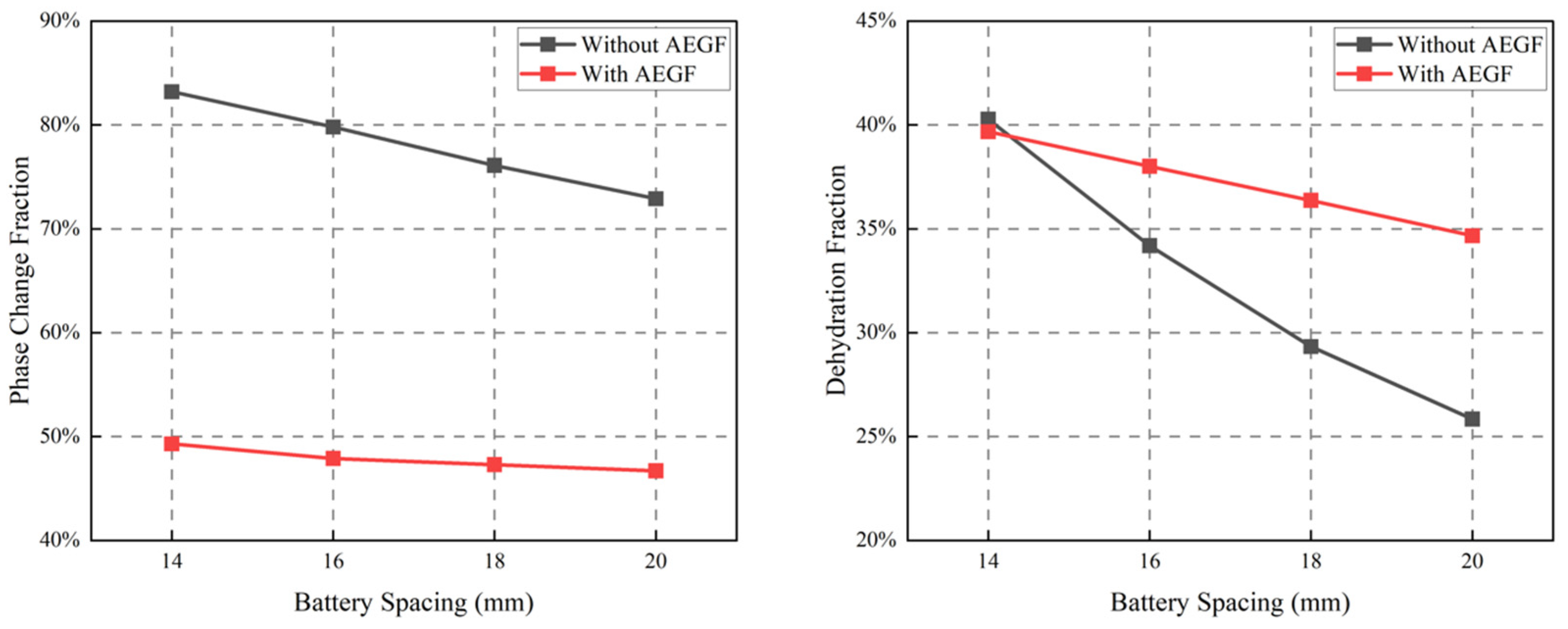
SAT-EG exhibits two-stage latent heat. Based on this characteristic, the phase change fraction and dehydration fraction of SAT-EG in the sandwich structures on both sides of the thermal runaway battery are calculated after thermal runaway occurs. Detailed data on the phase change fraction and dehydration fraction of SAT-EG on both sides of the thermal runaway battery at different battery spacings are shown in Figure 9 below.
Figure 9. Phase change fraction and dehydration fraction of SAT-EG on both sides of the thermal runaway battery at different battery spacings.
When only SAT-EG is used for protection, the phase change fraction of SAT-EG on both sides of the thermal runaway battery under the four battery spacings is 83.2%, 79.8%, 76.1% and 72.9%, respectively, and the dehydration fractions are 40.3%, 34.2%, 29.3% and 25.8%, respectively. After adding 2 mm thick AEGF to form a sandwich structure, the phase change fraction of SAT-EG on both sides of the thermal runaway battery under the four battery spacings is 49.3%, 47.9%, 47.3% and 46.7%, respectively, and the dehydration fractions are 39.7%, 38.0%, 36.4% and 34.7%, respectively.
It can be seen that the phase change fraction of SAT-EG on both sides of the thermal runaway battery under SAT-EG protection alone is much higher than that under the protection of the sandwich structure with 2 mm thick AEGF. The dehydration fractions of SAT-EG on both sides of the thermal runaway battery under the two schemes are close at a battery spacing of 14 mm. When the battery spacing is larger than 14 mm, the dehydration fraction under SAT-EG protection is lower than that under the sandwich structure protection.
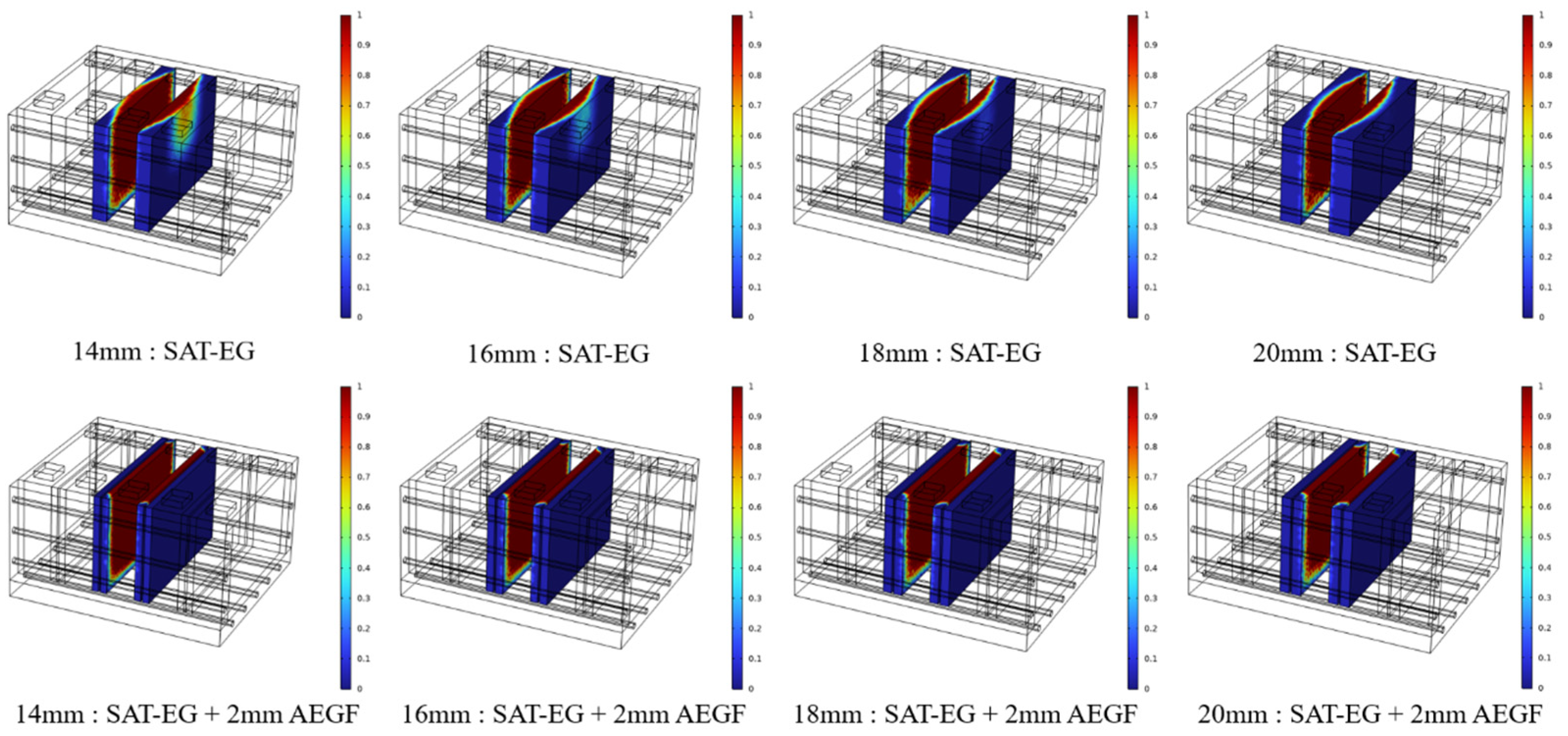
This indicates that after adding 2 mm thick AEGF since AEGF divides SAT-EG into two parts, the amount of SAT-EG that actually exerts the first-stage phase change effect is reduced. Only the SAT-EG closely attached to the thermal runaway battery can fully exert its latent heat effect, resulting in an increased dehydration fraction, while the latent heat effect of the SAT-EG on the other side is restricted, which advances the thermal runaway trigger time of the thermal runaway battery.
Figure 10 shows the contour plots of dehydration fraction of SAT-EG under two protection conditions at different battery spacings. This figure illustrates the distribution of the dehydration fraction of SAT-EG on both sides of the thermal runaway battery after the completion of heat release. When protected by SAT-EG alone, due to the liquid cooling effect on the side and bottom surfaces, the decomposition of SAT-EG mainly concentrates in the upper-central region, while the surrounding regions hardly decompose under the cooling effect. When protected by the sandwich structure, since AEGF divides SAT-EG into two regions and blocks heat transfer, a large amount of heat accumulates in the SAT-EG region adjacent to the thermal runaway battery, leading to nearly complete dehydration, whereas the SAT-EG on the other side hardly decomposes owing to the thermal barrier of AEGF.
Figure 10. Contour plots of dehydration fraction of SAT-EG under two protection conditions at different battery spacings.
Since SAT-EG releases latent heat via phase change in the first stage and chemical decomposition in the second stage, SAT-EG that undergoes only the first-stage phase change can recover and function repeatedly after the battery module cools down. In contrast, SAT-EG that undergoes second-stage chemical decomposition is irreversible and acts as a consumable during protection; the material must be replaced after thermal runaway.

3.3. Effect of AEGF Area on Thermal Runaway Protection of Battery Modules

3.3.1. Effect of AEGF Area on the Temperature of Bat2

As can be seen from the previous section, after AEGF is incorporated into SAT-EG to form a sandwich structure, the maximum temperature of Bat2 can be effectively controlled below T1. However, only one side of the SAT-EG in the structure can function fully, resulting in reduced utilization and insufficient latent heat release, which advances the thermal runaway trigger time of Bat3. To address this issue, this section adjusts the AEGF area ratio while keeping its thickness at 2 mm and ensuring the temperature of Bat2 remains below T1, so as to delay the thermal runaway trigger time of Bat3.
Since liquid cooling plates are installed on both sides and the bottom of the battery module, the heat generated by thermal runaway can be dissipated in a timely manner. Consequently, after thermal runaway occurs in the Bat3, the generated heat is mainly concentrated in the middle and upper regions of the battery module, as illustrated in Figure 7b. Based on this heat transfer characteristic, AEGF with different area ratios is combined with SAT-EG to form an alternative sandwich structure. In this structure, AEGF is arranged at the middle and upper positions, and the corresponding geometric model is shown in Figure 11. This design aims to fully utilize the latent heat of SAT-EG to suppress heat propagation after the thermal runaway of the Bat3, thereby controlling the temperature rise in the Bat2 and delaying the thermal runaway triggering time of the Bat3.
Figure 11. Geometric model of the battery module with partial area ratio AEGF combined with SAT-EG: (a) position of the AEGF in battery module; (b) battery module planform; (c) AEGF and SAT-EG dimensions.
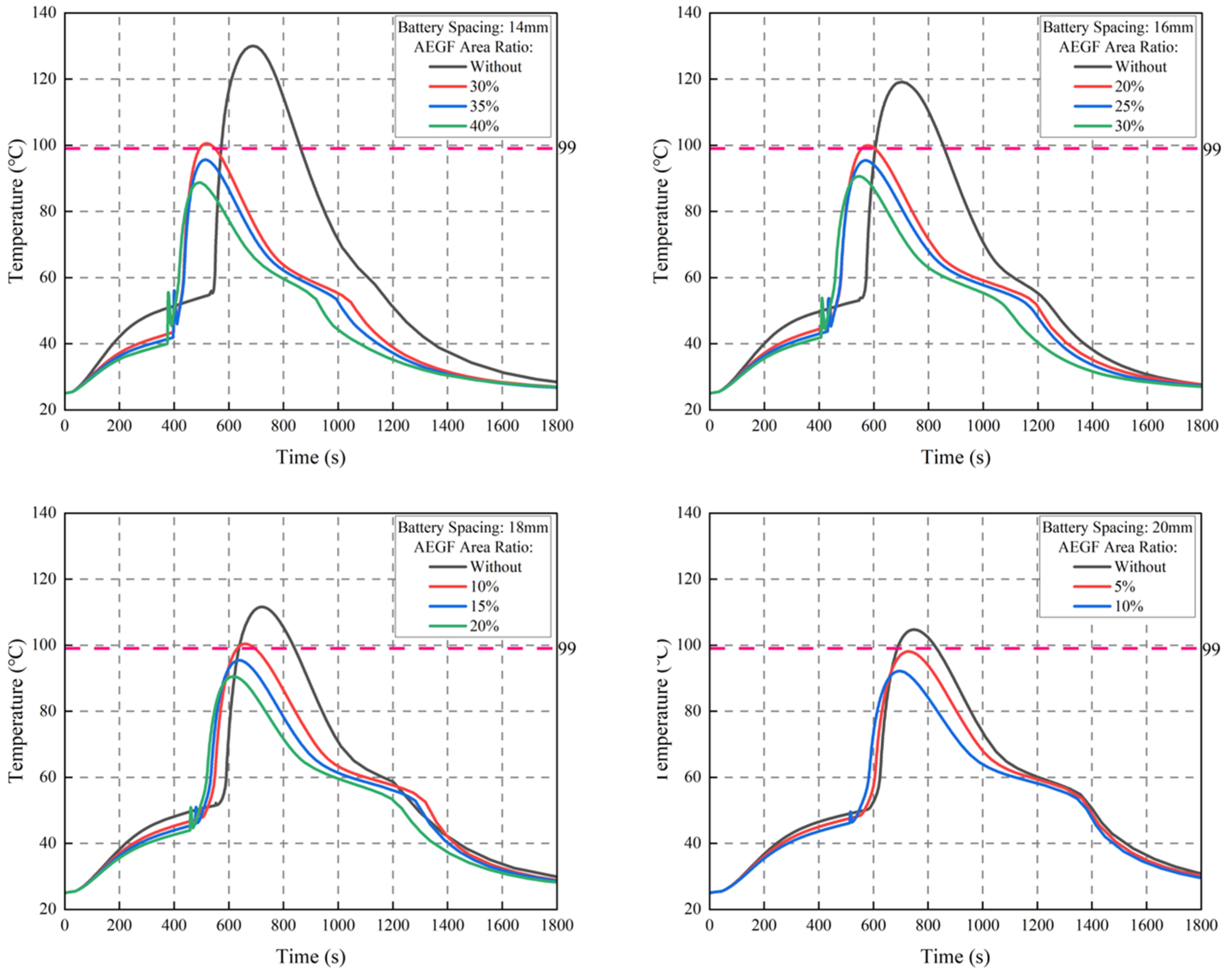
When the maximum temperature of Bat2 approaches T1 but remains below it, the corresponding area ratio of AEGF is regarded as the optimal area ratio, and the thermal runaway trigger time of Bat3 is the longest under this scheme. This section investigates the optimal area ratio of AEGF at different battery spacings, so as to control the maximum temperature of Bat2 and prolong the thermal runaway trigger time of Bat3.
As illustrated in Figure 12, adjusting the coverage area of AEGF can effectively keep the temperature of the Bat2 below T1. At the same battery spacing, increasing the AEGF area gradually enhances the capability of the sandwich structure to restrain thermal runaway propagation, which lowers the peak temperature of the Bat2 and, meanwhile, shortens the time required for its temperature to reach the maximum value. This is because an increase in AEGF area leads to a larger divided volume of SAT-EG, resulting in a relative reduction in the amount of SAT-EG that can fully exert its latent heat effect.
Figure 12. Temperature-time curves of Bat2 corresponding to AEGF with different area ratios under different battery spacings.
The optimal AEGF coverage area for maintaining the temperature of the Bat2 below T1 varies with different battery spacings. At battery spacings of 14–20 mm, the corresponding optimal area ratios are 35%, 25%, 15% and 5%, respectively, with the maximum temperatures of the Bat2 reaching 95.62 °C, 95.46 °C, 95.46 °C and 98.13 °C, respectively.

3.3.2. Effect of AEGF Area on Thermal Runaway Time of Bat3

As can be seen from the previous subsection, the optimal AEGF area ratios corresponding to the sandwich interlayer at battery spacings of 14–20 mm are 35%, 25%, 15% and 5%. This subsection investigates the variation in the thermal runaway trigger time of Bat3 under the optimal AEGF area ratio conditions.
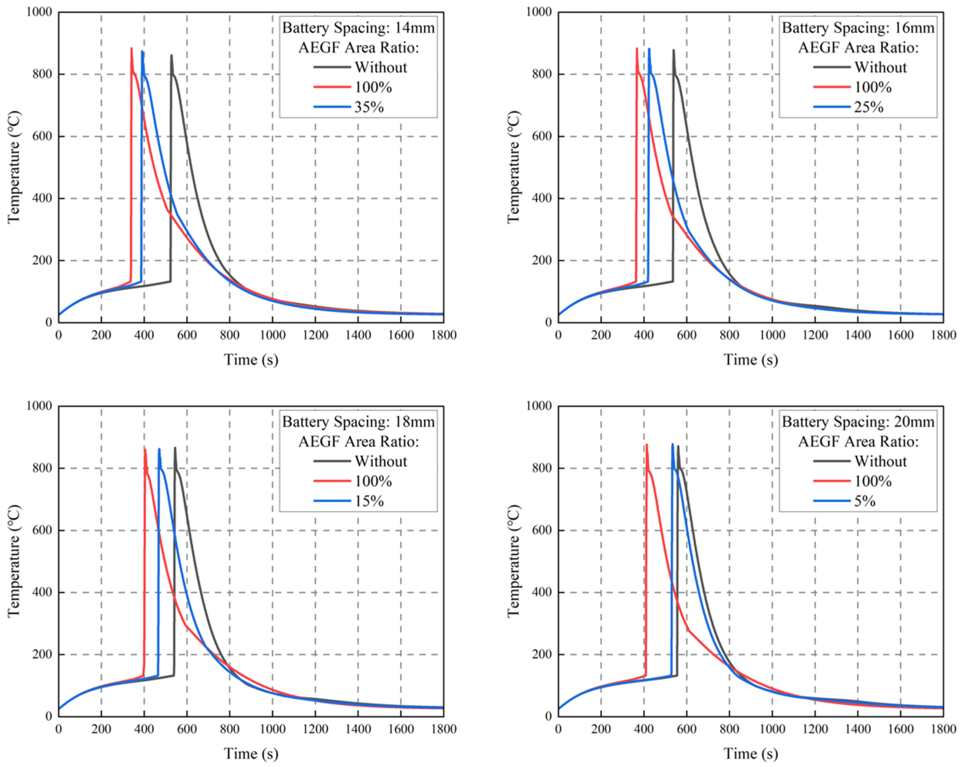
As can be seen from Figure 13, at the same battery spacing, the thermal runaway trigger time of Bat 3 corresponding to the AEGF with the optimal area ratio is effectively prolonged compared with the scheme using AEGF with 100% area ratio. Meanwhile, the larger the battery spacing, the more significant the prolongation effect of the thermal runaway trigger time. As shown in Table 8, at battery spacings of 14–20 mm, the thermal runaway trigger time of Bat3 is delayed by 50 s, 56 s, 70 s and 120 s, respectively.
Figure 13. Temperature–time curves of Bat3 at different AEGF area ratios and various battery spacings.
Table 8. Thermal runaway time of Bat3 at different AEGF area ratios and various battery spacings.
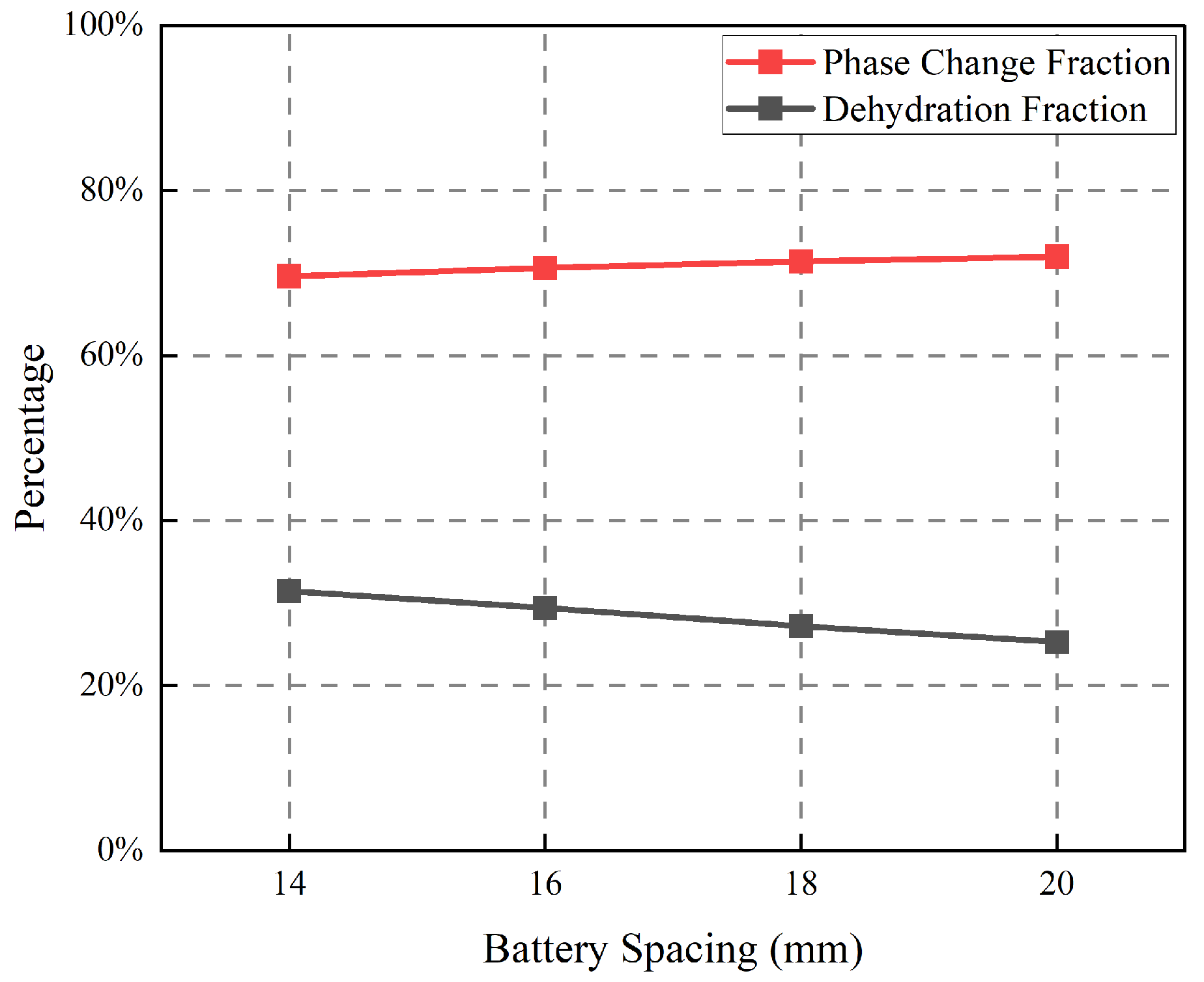
Figure 14 shows the phase change fraction and dehydration fraction of SAT-EG on both sides of the thermal runaway battery at the optimal AEGF area ratio under different battery spacings. The phase change fractions under the four battery spacings are 69.6%, 70.6%, 71.4% and 72.0%, respectively, and the dehydration fractions are 31.5%, 29.4%, 27.2% and 25.3%, respectively. Compared with the scheme using AEGF with 100% area ratio, the phase change fraction of SAT-EG is greatly improved under the four battery spacings, while the dehydration fraction is reduced. This indicates that after reducing the AEGF area ratio, the originally blocked SAT-EG can be connected, more SAT-EG exerts the first-stage phase change latent heat effect, and less SAT-EG undergoes the second-stage chemical decomposition. As a result, SAT-EG can utilize its latent heat more efficiently, and the overall utilization rate is improved, thus prolonging the thermal runaway trigger time of Bat3.
Figure 14. Phase change fraction and dehydration fraction of SAT-EG on both sides of the thermal runaway battery at the optimal AEGF area ratio under different battery spacings.
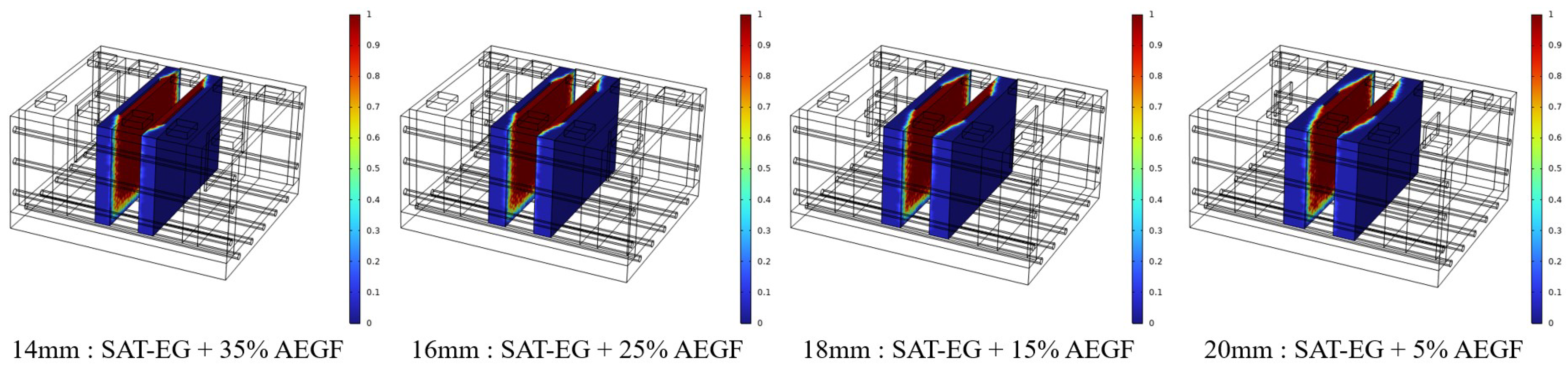
Figure 15 presents the contour plots of dehydration fraction of SAT-EG on both sides of the thermal runaway battery at the optimal AEGF area ratio under different battery spacings. Under this scheme, the distribution of the dehydration fraction of SAT-EG gradually approaches that of the scheme without AEGF as the battery spacing increases. This scheme avoids the drawback of the sandwich structure where only the SAT-EG adjacent to the thermal runaway battery can fully exert its latent heat and improves the overall latent heat utilization efficiency of SAT-EG. While controlling the maximum temperature of Bat2 below T1, it also effectively delays the thermal runaway trigger time of Bat3.
Figure 15. Contour plots of dehydration fraction of SAT-EG on both sides of the thermal runaway battery at the optimal AEGF area ratio under different battery spacings.

4. Conclusions

This study focuses on the problem of thermal runaway propagation in prismatic lithium-ion battery modules and proposes a collaborative protection strategy based on the integration of SAT-EG, AEGF, and liquid cooling systems. The main conclusions are as follows:
(1)
PA-EG is difficult to suppress the propagation of thermal runaway in battery modules. The heat generated by thermal runaway batteries is rapidly transferred to surrounding batteries, triggering large-scale thermal runaway. When the thickness of SAT-EG reaches 14 mm, it can suppress thermal runaway propagation, but the maximum temperature of adjacent batteries approaches T2. When the battery spacing reaches 20 mm, the maximum temperature of adjacent batteries is still higher than T1, accompanied by intense internal side reactions.
(2)
The composite structure of SAT-EG and AEGF can effectively block thermal runaway propagation and control the maximum temperature of adjacent batteries below T1. However, in the sandwich structure on both sides of the thermal runaway battery, the phase change fraction of SAT-EG decreases significantly, the dehydration fraction increases, and the thermal runaway trigger time of the thermal runaway battery is greatly advanced. This is because AEGF divides SAT-EG into two parts, and only the SAT-EG close to the thermal runaway battery can function, resulting in a decline in the overall utilization of SAT-EG.
(3)
On the premise that the maximum temperature of batteries adjacent to the thermal runaway battery does not exceed T1, reducing the AEGF area ratio can alter the heat transfer characteristics inside the battery module. The role of AEGF changes from complete thermal insulation to partial thermal insulation, thereby effectively improving the phase change fraction and overall utilization of SAT-EG, significantly delaying the thermal runaway trigger time of the thermal runaway battery, and gaining time for the detection and handling of thermal runaway.
In this study, numerical simulations were performed on thermal runaway propagation characteristics of prismatic lithium battery modules. To improve computational efficiency and reduce solving difficulty, the model was simplified, leading to deviations from actual complex operating conditions with the following limitations. Firstly, constant thermophysical parameters at room temperature were adopted, which weakened the strong nonlinear characteristics of thermal runaway. Secondly, only solid heat conduction was considered in modeling, while local thermal radiation under high-temperature conditions was neglected. Finally, the internal heterogeneous structures of batteries were not distinguished, failing to accurately reflect the detailed internal heat generation and heat transfer processes. In future research, model errors can be corrected by introducing temperature-dependent dynamic thermophysical parameters, coupling convective and radiative boundaries, and establishing refined heterogeneous battery models, so as to further enhance the authenticity and prediction accuracy of simulations.

Author Contributions

Conceptualisation, L.X. and T.Y.; methodology, L.T. and C.X.; software, H.X. and Q.X.; validation, M.L. and L.C.; formal analysis, H.Z. and J.X.; investigation, C.X. and H.X.; resources, L.X. and T.Y.; data curation, M.L. and L.C.; writing—original draft preparation, L.T. and C.X.; writing—review and editing, L.X. and T.Y.; visualization, L.T. and Q.X.; supervision, H.Z. and J.X.; project administration, L.X. and T.Y.; funding acquisition, Q.X. and H.Z. All authors have read and agreed to the published version of the manuscript.

Funding

This research is funded by the Joint Fund Project of Natural Science Foundation of Hubei Province of China (2025AFD087) and the National Natural Science Foundation of China (52476079).

Data Availability Statement

The original contributions presented in this study are included in the article. Further inquiries can be directed to the corresponding authors.

Conflicts of Interest

Liang Tong, Chengfu Xie, Hanwei Xu, Linzhi Xu, Qianqian Xin, Tianqi Yang, Hengyun Zhang, Jinsheng Xiao have no conflicts of interest. Min Liu and Lingyu Chen work for Research Institute of State Grid Zhejiang Electric Power Co., Ltd.

References

  1. Jia, Z.; Jin, K.; Mei, W.; Qin, P.; Sun, J.; Wang, Q. Advances and perspectives in fire safety of lithium-ion battery energy storage systems. eTransp 2025, 24, 100390. [Google Scholar] [CrossRef]
  2. Li, M.; Dong, C.; Yu, X.; Xiao, Q.; Jia, H. Multi-step ahead thermal warning network for energy storage system based on the core temperature detection. Sci. Rep. 2021, 11, 15332. [Google Scholar] [CrossRef]
  3. Bu, Y.; Wu, Y.; Li, X.; Pei, Y. Operational risk analysis of a containerized lithium-ion battery energy storage system based on STPA and fuzzy evaluation. Process Saf. Environ. Prot. 2023, 176, 627–640. [Google Scholar] [CrossRef]
  4. He, M.; Chartouni, D.; Landmann, D.; Colombi, S. Safety Aspects of Stationary Battery Energy Storage Systems. Batteries 2024, 10, 418. [Google Scholar] [CrossRef]
  5. Theodore, A.M. Structural, electrical, and electrochemical studies of the olivine LiMPO4 (M= Fe, Co, Cr, Mn, V) as cathode materials for lithium-ion rechargeable batteries based on the intercalation principle. Mater. Open Res. 2023, 2, 11. [Google Scholar] [CrossRef]
  6. Niu, H.; Zhang, N.; Lu, Y.; Zhang, Z.; Li, M.; Liu, J.; Song, W.; Zhao, Y.; Miao, Z. Strategies toward the development of high-energy-density lithium batteries. J. Energy Storage 2024, 88, 111666. [Google Scholar] [CrossRef]
  7. Sun, T.; Yan, Y.; Wang, X.; Rasool, G.; Zhang, K.; Li, T. A comprehensive study on heat transfer mechanism and thermal runaway suppression of the lithium-ion battery. Int. J. Heat Mass Transfer 2025, 245, 127027. [Google Scholar] [CrossRef]
  8. Zhou, Z.; Li, M.; Zhou, X.; Ju, X.; Yang, L. Investigating thermal runaway characteristics and trigger mechanism of the parallel lithium-ion battery. Appl. Energy 2023, 349, 121690. [Google Scholar] [CrossRef]
  9. Mao, T.; Xiao, Y.; Cheng, X.; Pan, Y.; Li, L.; Yang, J.; Zhang, H.; Yang, H.; Zhao, J. Effects and mechanisms of thickness-tunable aerogel thermal barriers on suppression of thermal runaway propagation in large-format prismatic lithium-ion batteries. Mater. Today Energy 2025, 53, 101996. [Google Scholar] [CrossRef]
  10. Yan, W.; Huang, W.; Yang, Y.; Wei, Z.; Zhen, H.; Lin, Y. Research on overcharge mitigations and thermal runaway risk of 18650 lithium-ion batteries. J. Energy Storage 2025, 120, 116372. [Google Scholar] [CrossRef]
  11. Xu, J.; Mei, W.; Zhao, C.; Liu, Y.; Zhang, L.; Wang, Q. Study on thermal runaway mechanism of 1000 mAh lithium-ion pouch cell during nail penetration. J. Therm. Anal. Calorim. 2021, 144, 273–284. [Google Scholar] [CrossRef]
  12. Ouyang, D.; Chung, Y.; Liu, J.; Bai, J.; Zhou, Y.; Chen, S.; Wang, Z.; Shu, C. Characteristics and mechanisms of as well as evaluation methods and countermeasures for thermal runaway propagation in lithium-ion batteries. Prog. Energy Combust. Sci. 2025, 108, 101209. [Google Scholar] [CrossRef]
  13. Liu, J.; Ma, Z.; Guo, Z.; Zhao, W.; Wang, S.; Zhao, H.; Ren, L. Experimental investigation on mechanical-electrochemical coupling properties of cylindrical lithium-ion batteries. Energy 2024, 293, 130536. [Google Scholar] [CrossRef]
  14. Chai, Z.; Li, J.; Liu, Z.; Liu, Z.; Jin, X. Experimental analysis and safety assessment of thermal runaway behavior in lithium iron phosphate batteries under mechanical abuse. Sci. Rep. 2024, 14, 8673. [Google Scholar] [CrossRef]
  15. Chai, Z.; Liu, Z.; Xue, Q.; Xiao, Y.; Tan, P.; Qiu, M.; Li, J. Efficient coupled mechanical-electrical-thermal modeling and safety assessment of lithium-ion battery under mechanical abuse. J. Energy Storage 2025, 114, 115917. [Google Scholar] [CrossRef]
  16. Xiao, Y.; Yang, F.; Gao, Z.; Liu, M.; Wang, J.; Kou, Z.; Lin, Y.; Li, Y.; Gao, L.; Chen, Y.; et al. Review of mechanical abuse related thermal runaway models of lithium-ion batteries at different scales. J. Energy Storage 2023, 64, 107145. [Google Scholar] [CrossRef]
  17. Gui, Q.; Jin, B.; Liu, P.; Yu, K.; Zhang, J.; Mao, L. Revealing the Hazard of Mild Electrical Abuse on the Safety Characteristics of NaNi1/3Fe1/3Mn1/3O2 Cathode Sodium-Ion Battery. Adv. Sci. 2025, 12, 2501649. [Google Scholar] [CrossRef] [PubMed]
  18. Xu, X.; Sun, X.; Zhao, L.; Li, R.; Tang, W. Research on thermal runaway characteristics of NCM lithium-ion battery under thermal-electrical coupling abuse. Ionics 2022, 28, 5449–5467. [Google Scholar] [CrossRef]
  19. Liu, S.; Guo, Q.; Zhang, J.; Huang, Z.; Han, D. Investigation on thermal runaway behaviors and gas generation dynamics of lithium-ion batteries induced by electrical abuse at low-pressure conditions. J. Energy Storage 2025, 125, 116855. [Google Scholar] [CrossRef]
  20. Feng, X.; Ouyang, M.; Liu, X.; Lu, L.; Xia, Y.; He, X. Thermal runaway mechanism of lithium-ion battery for electric vehicles: A review. Energy Storage Mater. 2018, 10, 246–267. [Google Scholar] [CrossRef]
  21. Wei, D.; Zhang, M.; Zhu, L.; Chen, H.; Huang, W.; Yao, J.; Yuan, Z.; Xu, C.; Feng, X. Study on thermal runaway behavior of Li-ion batteries using different abuse methods. Batteries 2022, 8, 201. [Google Scholar] [CrossRef]
  22. Kwak, E.; Kim, J.; Hong, S.; Oh, K. Detailed modeling investigation of thermal runaway pathways of a lithium iron phosphate battery. Int. J. Energy Res. 2022, 46, 1146–1167. [Google Scholar] [CrossRef]
  23. Su, L.; Yang, F.; Hu, W.; Chen, S.; Lyu, N. Thermal runaway gas generation of lithium iron phosphate batteries triggered by various abusive conditions. J. Energy Eng. 2024, 150, 04024017. [Google Scholar] [CrossRef]
  24. Abada, S.; Marlair, G.; Lecocq, A.; Petit, M.; Sauvant-Moynot, V.; Huet, F. Safety focused modeling of lithium-ion batteries: A review. J. Power Sources 2016, 306, 178–192. [Google Scholar] [CrossRef]
  25. Zhi, M.; Fan, R.; Zheng, L.; Yue, S.; Pan, Z.; Sun, Q.; Liu, Q. Experimental investigation on hydrated salt phase change material for lithium-ion battery thermal management and thermal runaway mitigation. Energy 2024, 307, 132685. [Google Scholar] [CrossRef]
  26. Liu, J.; Zhang, X.; Xi, Y.; Xu, S.; Zhang, Z. A comprehensive review of hybrid liquid and PCM cooling BTMS. J. Therm. Anal. Calorim. 2025, 150, 20539–20572. [Google Scholar] [CrossRef]
  27. Liu, H.; Wei, Z.; He, W.; Zhao, J. Thermal issues about Li-ion batteries and recent progress in battery thermal management systems: A review. Energy Convers. Manag. 2017, 150, 304–330. [Google Scholar] [CrossRef]
  28. Mohamed, S.; Al-Sulaiman, F.; Ibrahim, N.; Zahir, M.; Al-Ahmed, A.; Saidur, R.; Yılbas, B.; Sahin, A. A review on current status and challenges of inorganic phase change materials for thermal energy storage systems. Renew. Sustain. Energy Rev. 2017, 70, 1072–1089. [Google Scholar] [CrossRef]
  29. Cao, J.; Ling, Z.; Lin, S.; He, Y.; Fang, X.; Zhang, Z. Thermochemical heat storage system for preventing battery thermal runaway propagation using sodium acetate trihydrate/expanded graphite. Chem. Eng. J. 2022, 433, 133536. [Google Scholar] [CrossRef]
  30. Liu, Q.; Zhu, Q.; Zhu, W.; Yi, X. Influence of aerogel felt with different thickness on thermal runaway propagation of 18650 lithium-ion battery. J. Electrochem. 2022, 90, 087003. [Google Scholar] [CrossRef]
  31. Nasar, M.; Vieira, R.; Gross, L.; Kollmeyer, P.; Ahmed, R.; Habibi, S. Comparative Analysis of Active Liquid Cooling Strategies for High-Power Lithium-Ion Battery Modules. In Proceedings of the 2025 IEEE/AIAA Transportation Electrification Conference and Electric Aircraft Technologies Symposium (ITEC+EATS), Anaheim, CA, USA, 18–20 June 2025; pp. 1–6. [Google Scholar]
  32. Sen, S.; Mahdi, J.; Talebizadehsardari, P.; Rocca, A.; Cairns, A. Enhanced thermal management of lithium-ion pouch cells via hybrid approach of phase change material-liquid cooling. Int. Commun. Heat Mass Transfer 2025, 165, 108997. [Google Scholar] [CrossRef]
  33. Xiao, H.; E, J.; Tian, S.; Huang, Y.; Song, X. Effect of composite cooling strategy including phase change material and liquid cooling on the thermal safety performance of a lithium-ion battery pack under thermal runaway propagation. Energy 2024, 295, 131093. [Google Scholar] [CrossRef]
  34. Wilke, S.; Schweitzer, B.; Khateeb, S.; Al-Hallaj, S. Preventing thermal runaway propagation in lithium-ion battery packs using a phase change composite material: An experimental study. J. Power Sources 2017, 340, 51–59. [Google Scholar] [CrossRef]
  35. Jin, C.; Sun, Y.; Wang, H.; Zheng, Y.; Wang, S.; Rui, X.; Xu, C.; Feng, X.; Wang, H.; Ouyang, M. Heating power and heating energy effect on the thermal runaway propagation characteristics of lithium-ion battery module: Experiments and modeling. Appl. Energy 2022, 312, 11876. [Google Scholar] [CrossRef]
  36. Chen, M.; Zhu, M.; Zhao, L.; Chen, Y. Study on thermal runaway propagation inhibition of battery module by flame-retardant phase change material combined with aerogel felt. Appl. Energy 2024, 367, 123394. [Google Scholar] [CrossRef]
  37. Yang, T.; Xu, H.; Xie, C.; Xu, L.; Liu, M.; Chen, L.; Xin, Q.; Zeng, J.; Zhang, H.; Xiao, J. A Thermal Runaway Protection Strategy for Prismatic Lithium-Ion Battery Modules Based on Phase Change and Thermal Decomposition of Sodium Acetate Trihydrate. Batteries 2025, 11, 198. [Google Scholar] [CrossRef]
Disclaimer/Publisher’s Note: The statements, opinions and data contained in all publications are solely those of the individual author(s) and contributor(s) and not of MDPI and/or the editor(s). MDPI and/or the editor(s) disclaim responsibility for any injury to people or property resulting from any ideas, methods, instructions or products referred to in the content.

Article Metrics

Citations

Article Access Statistics

Multiple requests from the same IP address are counted as one view.