1. Introduction
Lithium-ion batteries have become the dominant energy storage technology in electric vehicles, portable electronics, and grid-scale energy storage systems due to their high energy density and long cycle life. However, thermal issues remain a critical bottleneck for safety and durability [
1]. Elevated temperature accelerates degradation, and non-uniform temperature distribution aggravates performance imbalance, while abusive thermal conditions may trigger thermal runaway accompanied by fire and explosion hazards [
2,
3,
4]. Therefore, battery thermal management systems (BTMSs) are essential for maintaining cells within a safe temperature window and improving thermal uniformity at both cell and pack levels [
5]. This work focuses on capsule geometry optimization and novel MicroPCM 28D formulations to investigate their combined effects on battery thermal management performance under forced convection conditions.
Among various BTMS strategies, air cooling is attractive due to its simplicity and low cost, but its heat removal capability can be insufficient under high heat flux conditions. As a complementary approach, phase change materials (PCMs) have been extensively explored because latent heat absorption during melting can effectively buffer temperature rise during transient heating [
6,
7]. PCM selection, thermal storage mechanisms, and practical implementation constraints have been widely reviewed, including fundamental PCM energy storage principles and broader PCM applications [
6], PCM-based thermal management in electronics and batteries [
7], and PCM families and selection guidelines for thermal storage [
8]. More recently, PCM-based BTMS research has advanced rapidly, and recent reviews summarize both progress and remaining challenges, such as limited thermal conductivity and regeneration issues under repeated cycling [
9].
A central limitation of most organic PCMs is their low intrinsic thermal conductivity, which restricts heat spreading and can delay heat extraction from the heat source. Microencapsulation and encapsulation technologies are frequently adopted to improve handling, mitigate leakage, and enable modular integration. A comprehensive review of solid–liquid PCMs and encapsulation technologies provides the key design considerations for encapsulated PCM systems [
10]. In parallel, recent microcapsule studies highlight the opportunity to integrate thermally conductive reinforcements into PCM microcapsules to improve effective heat transfer while retaining latent heat storage functionality [
11]. These encapsulation concepts motivate capsule-based PCM configurations in battery thermal management, where geometry and packaging can be deliberately engineered.
To further enhance heat transfer, nano-enhanced PCMs and composite PCMs have been widely studied. Reviews on thermal conductivity enhancement of PCMs summarize the roles of conductive fillers, percolation pathways, and processing strategies, while also emphasizing challenges such as dispersion stability and long-term reliability [
12]. Recent comprehensive reviews of nano-enhanced PCMs further consolidate the advances in nanoparticle-based enhancement for thermal energy storage applications and discuss limitations associated with agglomeration, sedimentation, and viscosity-driven processing constraints [
13]. A recent review focusing on nano-enhanced PCMs in thermal management systems reinforces that conductivity enhancement is often accompanied by practical issues in manufacturability and stability, which remain critical barriers for real-world deployment [
14]. Representative experimental work has demonstrated that graphene and carbon nanotubes can significantly improve the thermal performance of composite PCMs and indicate their potential for lithium-ion power battery applications [
15]. In addition, advanced fabrication strategies such as alternating positive and negative pressures during perfusion have been reported to enhance the thermal conductivity of graphene-based phase change composites, illustrating continued progress in composite PCM processing [
16].
Besides material-level enhancement, structural and hybrid system-level designs are widely adopted to amplify PCM effectiveness. Fin-enhanced PCM designs increase heat transfer area and provide conductive pathways, and a recent system using internal–external fin-enhanced PCM demonstrates improved thermal management for cylindrical lithium-ion batteries [
17]. Similarly, integrating PCM with metal foam and fins has been investigated via parametric studies using CFD and data-driven models, emphasizing the coupled effects of PCM properties, enhanced structures, and operating conditions [
18]. Hybrid configurations that combine PCM with active cooling approaches further increase heat removal capability. An optimized channel design in a hybrid PCM–liquid cooling system demonstrates enhanced thermal management performance, especially under higher heat loads where passive buffering alone may be insufficient [
19]. Another hybrid PCM–heat-pipe–thermoelectric system illustrates the potential of multi-physics coupling to achieve stronger temperature suppression under demanding operating conditions [
20]. Recent experimental studies also validate that PCM-based passive thermal management can effectively reduce peak temperature in practical configurations, while highlighting the importance of system architecture and operating environment for sustained performance [
21]. Moreover, numerical and experimental investigations of hybrid BTMSs for high-rate applications further underscore that airflow and system-level heat transfer pathways strongly influence achievable temperature reduction [
22].
Despite these advances, two gaps remain highly relevant for PCM capsule-based BTMS design. First, most prior studies emphasize either composite PCM development or structural enhancements such as fins and metal foams, while the role of capsule geometry, especially its interaction with airflow regimes from weak convection to strong forced convection, is less systematically quantified. Second, although conductive nano-additives are widely used, long-term dispersion stability and sedimentation resistance remain practical challenges that can directly affect repeatability and durability of thermal performance. Addressing these gaps requires an experimentally grounded comparison coupling material formulation, capsule geometry, and controlled airflow conditions within a unified evaluation framework.
In recent studies, various hybrid heat dissipation approaches for battery packs have been investigated, including the development and optimization of hybrid heat dissipation systems [
23], comprehensive analyses of thermal heat dissipation for lithium-ion battery packs [
24], hybrid thermal systems incorporating composite PCMs [
25], and innovative 3D-printed hybrid cooling systems for pouch cells [
26,
27]. Building upon these studies, the present work experimentally investigates composite PCM capsules with multiple geometries under controlled airflow conditions. By systematically comparing peak temperature, steady-state characteristics, and cooling dynamics across airflow regimes, this study aims to provide design-relevant insights for geometry-regulated convection enhancement and stable nano-enhanced PCM capsule integration in lithium-ion battery thermal management.
2. Materials and Methods
A microencapsulated phase change material, MicroPCM 28D (Microtek Laboratories, Inc., Dayton, OH, USA), composed of a n-octadecane core encapsulated within a melamine-formaldehyde shell, was employed as the primary latent heat storage component. The microencapsulated phase change material MicroPCM 28D was commercially purchased, while paraffin wax was commercially obtained from an online supplier. The nano carbon black additive was provided by NASA Glenn Research Center. Paraffin wax was used as the reference phase change material. Nanocarbon black was incorporated as a thermally conductive additive. Conventional paraffin and nano carbon black systems often suffer from severe particle sedimentation due to the low viscosity of molten paraffin, resulting in non-uniform thermal distribution after solidification. In contrast, the incorporation of MicroPCM 28D significantly increases the effective viscosity of the liquid composite without substantially reducing the overall latent heat storage capacity. Even in the molten state, the 28D-based composite exhibits a noticeably thicker consistency compared with molten paraffin wax.
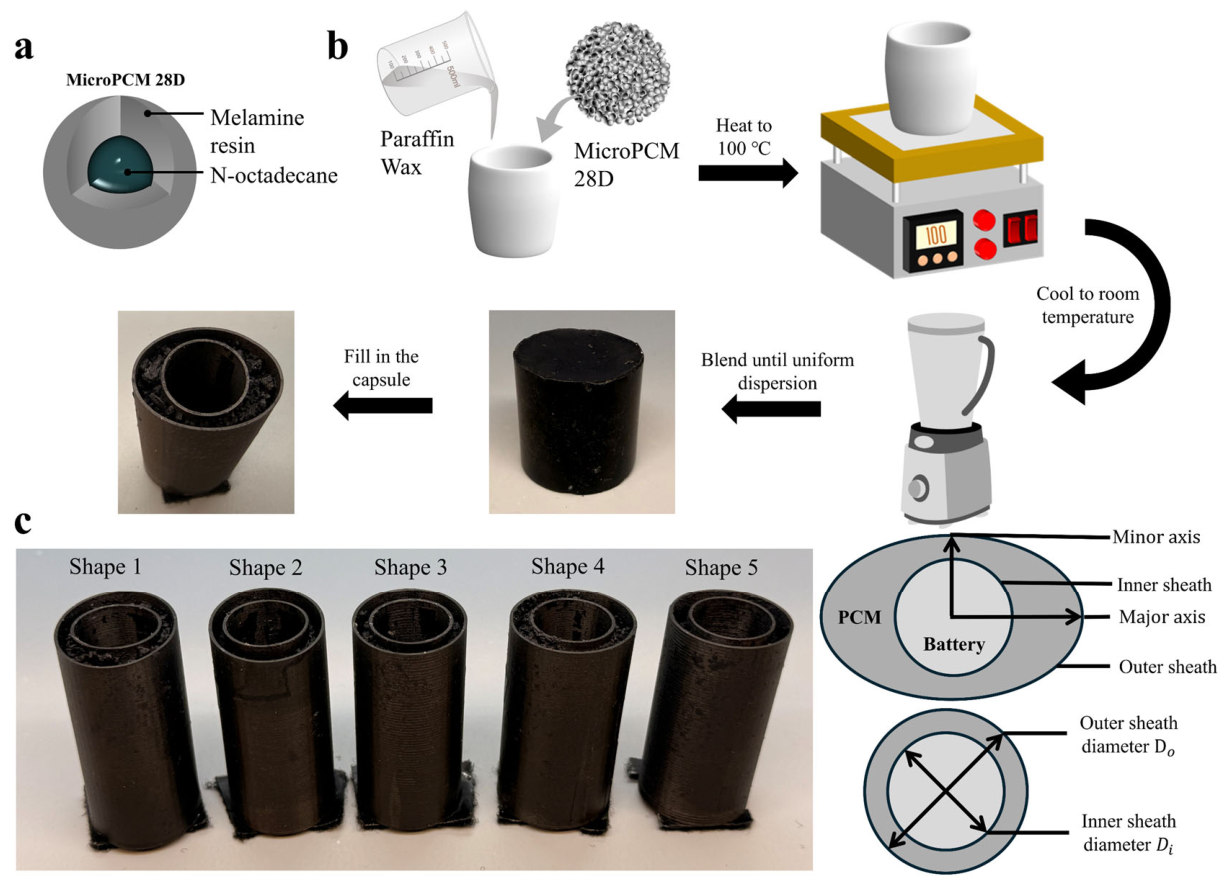
The MicroPCM 28D composite was prepared by mixing 40 wt% paraffin wax and 60 wt% MicroPCM 28D. The mixture was heated to 100 °C on a hot plate until complete melting was achieved, followed by continuous manual stirring using a glass rod to promote uniform dispersion and homogeneous liquefaction. Stirring was maintained for approximately 5–10 min until no visible phase separation or particle agglomeration was observed. Homogeneity was initially assessed based on visual inspection of uniform color and texture and further supported by consistent DSC phase-change behavior across repeated thermal cycles. The blending and cooling process is shown in
Figure 1b. After full melting, 2 wt% nano carbon black, relative to the total PCM mass of paraffin and 28D, was added and thoroughly mixed. Due to the high viscosity of the molten composite, direct casting into the capsule cavity was not feasible. After solidification, the composite was broken into small pieces and milled into micrometer-scale powder. The powder was then packed into the PCM storage region of the capsule. A post-filling thermal cycle was applied to remelt the composite inside the cavity, allowing the material to coalesce and eliminate internal voids. The smooth surface morphology of the solidified composite after cooling can be observed in
Figure 1b.
For comparison to a baseline material with no PCM, a reference material consisting of pure paraffin wax with 2 wt% nano carbon black was prepared via direct melt blending. Paraffin was heated to 100 °C, followed by the addition and stirring of nano carbon black until uniform dispersion was achieved. The molten composite was directly injected into the capsule cavity using a drop-casting method before solidification. All phase change materials were injected into the region between the inner and outer sheaths of the capsule, which was specifically designed as the PCM storage layer.
The five capsule geometries fabricated via 3D printing are shown in
Figure 1c. The capsules were manufactured using fused filament fabrication on a Markforged Mark 2 printer (Markforged Holding Corporation, Waltham, WA, USA). The printing filament was Onyx
®, a nylon-based composite reinforced with micro carbon fibers. Due to the relatively small thickness of the sheath compared with the PCM region, its contribution to thermal energy storage is limited. The integrated one-piece design reduced the risk of leakage during phase transition. Three oval geometries, labeled Shapes 1 to 3, and two circular geometries, labeled Shapes 4 and 5, were designed. All capsules maintained identical height and internal PCM volume, while geometric variations were introduced in the major and minor axes to modulate airflow interaction. The specific dimensions were listed in
Table 1. For each geometry, two capsules were prepared, one filled with the 28D composite and the other filled with the paraffin and carbon black composite.
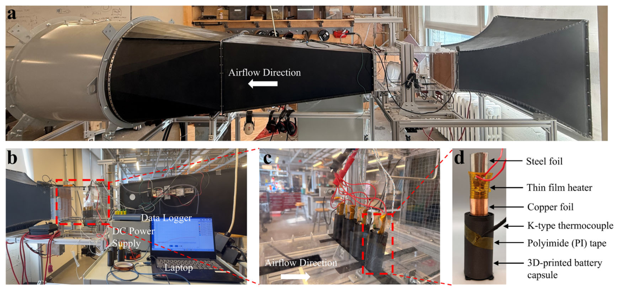
Thermal performance testing was conducted in a wind tunnel system, as illustrated in
Figure 2a. The airflow velocity was adjustable from 0 to 10 m/s with an accuracy of ±0.1 m/s. In practical battery cooling systems, lower airflow velocities in this range correspond to weak convection conditions such as natural convection or low-speed fan cooling, while higher airflow velocities represent strong forced-air cooling typically used in actively cooled battery modules. A honeycomb flow straightener was installed upstream of the test section to reduce turbulence intensity. The overall experimental configuration is shown in
Figure 2b. Four capsules were positioned inside the test chamber with a center-to-center spacing of 5.08 cm, as shown in
Figure 2c. During wind tunnel testing, all four capsules were simultaneously heated.
The heating assembly for a single capsule is presented in
Figure 2d. Heating was provided by a thin-film heater powered by a regulated DC supply at 9 V and 0.46 A, corresponding to a constant power input of 4.14 W per capsule. This heating level is comparable to the typical heat generation range of cylindrical lithium-ion cells under moderate-to-high discharge conditions and therefore represents realistic battery thermal management scenarios. The use of a thin-film heater also provides a spatially uniform heat source, enabling controlled comparison of geometry-dependent thermal performance independent of specific battery electrochemistry. A copper foil layer was placed between the thin-film heater and the inner sheath of the capsule to improve temperature uniformity. A steel foil layer was applied externally to ensure proper mechanical contact. K-type thermocouples were used to monitor temperature evolution. The inner-sheath thermocouple was positioned between the copper foil and the inner sheath to simulate battery core temperature. The outer-sheath thermocouple was attached to the external capsule surface using polyimide tape. All thermocouples were located at the mid-height of the capsule and positioned on the downstream side, where peak temperature is expected to occur. Temperature data were recorded using a data logger connected to a laptop for continuous acquisition.
3. Thermal Response Characteristics
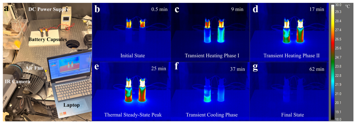
To understand the thermal regulation behavior of the proposed phase change composite, infrared thermography experiments were conducted under forced convection conditions. The experimental setup is illustrated in
Figure 3a, where two battery capsules were simultaneously tested under identical heating and airflow conditions. Shape 3 was selected as a representative case because its aspect ratio is close to unity while still maintaining an oval geometry, providing an intermediate configuration between elongated and circular shapes. One capsule was filled with the MicroPCM 28D composite material, while the other contained a baseline conventional wax-based composite with 2 wt% nano carbon black. The heating process was powered by a DC power supply, and the temperature evolution of the capsule surfaces was recorded by an infrared camera. Representative thermal images captured during the heating and cooling process are presented in
Figure 3b–g.
Figure 3b shows the initial state of the capsules before heating, where both samples remain near the ambient temperature of 20 °C. As heating begins, the temperature gradually increases and enters the first transient heating stage, as shown in
Figure 3c at 9 min. During this stage, the temperature rise is mainly governed by sensible heat storage in the composite materials. As heating continues, the capsules enter a second transient heating stage, shown in
Figure 3d at 17 min, where phase change gradually begins, and latent heat storage starts to influence the temperature evolution. The peak temperature state is observed in
Figure 3e at 25 min, corresponding to the thermal steady-state condition of the system, where the temperature variation becomes minimal. After the heating power is turned off, the capsules undergo a transient cooling stage as shown in
Figure 3f at 37 min, followed by the final state where the capsules return close to the ambient temperature at around 62 min, as illustrated in
Figure 3g. The full thermal cycle presented in
Figure 3 therefore provides a direct visualization of the transient heating, steady-state, and cooling processes that occur in the phase change thermal management system.
The thermophysical properties of the two composite materials used in the experiment are summarized in
Table 2. The MicroPCM 28D composite and the baseline wax composite exhibit similar densities (872 and 800 kg·m
−3, respectively). However, the thermal conductivity of the MicroPCM 28D composite increases from 0.2497 W·m
−1·K
−1 for the wax composite to 0.3775 W·m
−1·K
−1, corresponding to an enhancement of approximately 51%. Similarly, the thermal diffusivity increases from 0.1607 mm
2·s
−1 to 0.3742 mm
2·s
−1, representing an increase of about 133%. These enhanced thermal transport properties contribute to faster heat propagation inside the composite material and more efficient heat redistribution within the capsule. The latent heat of the MicroPCM 28D composite (140,000 J·kg
−1) remains comparable to that of the wax composite (173,400 J·kg
−1), indicating that the incorporation of MicroPCM 28D maintains significant phase change energy storage capability while improving thermal transport performance.
Another important difference between the two systems lies in their rheological behavior during melting. Previous studies have shown that mixtures containing approximately 60 wt% microencapsulated PCM particles can exhibit slurry-like or paste-like characteristics due to particle–particle interactions that form a spatial network structure [
22]. This network structure significantly increases the effective viscosity of the mixture and suppresses liquid flow during melting. In the present work, this property plays a critical role in stabilizing the dispersion of nano carbon black particles inside the composite material. This stability is important for long-term battery operation, as sedimentation could lead to non-uniform thermal conductivity and localized overheating. In contrast to conventional paraffin systems, where nano additives tend to sediment over time, the high-viscosity nature of the 28D composite effectively prevents particle sedimentation and ensures a uniform distribution of thermal conductivity enhancers throughout the material.
Based on the experimental observations in
Figure 3 and the thermophysical properties summarized in
Table 2, the thermal behavior of the capsule system can be described using a unified thermal response framework. During the initial heating stage, heat is primarily stored through sensible heat accumulation in the composite material. As the temperature approaches the phase change range of the PCM, latent heat storage becomes the dominant mechanism that buffers the temperature rise. Once the latent heat storage capacity is exhausted, the system reaches the thermal steady-state peak temperature. After the heating power is removed, the stored thermal energy is gradually released during the cooling stage through both convective heat transfer and phase change solidification. This thermal response system provides the basis for the quantitative comparison of capsule geometries and airflow conditions presented in the following section.
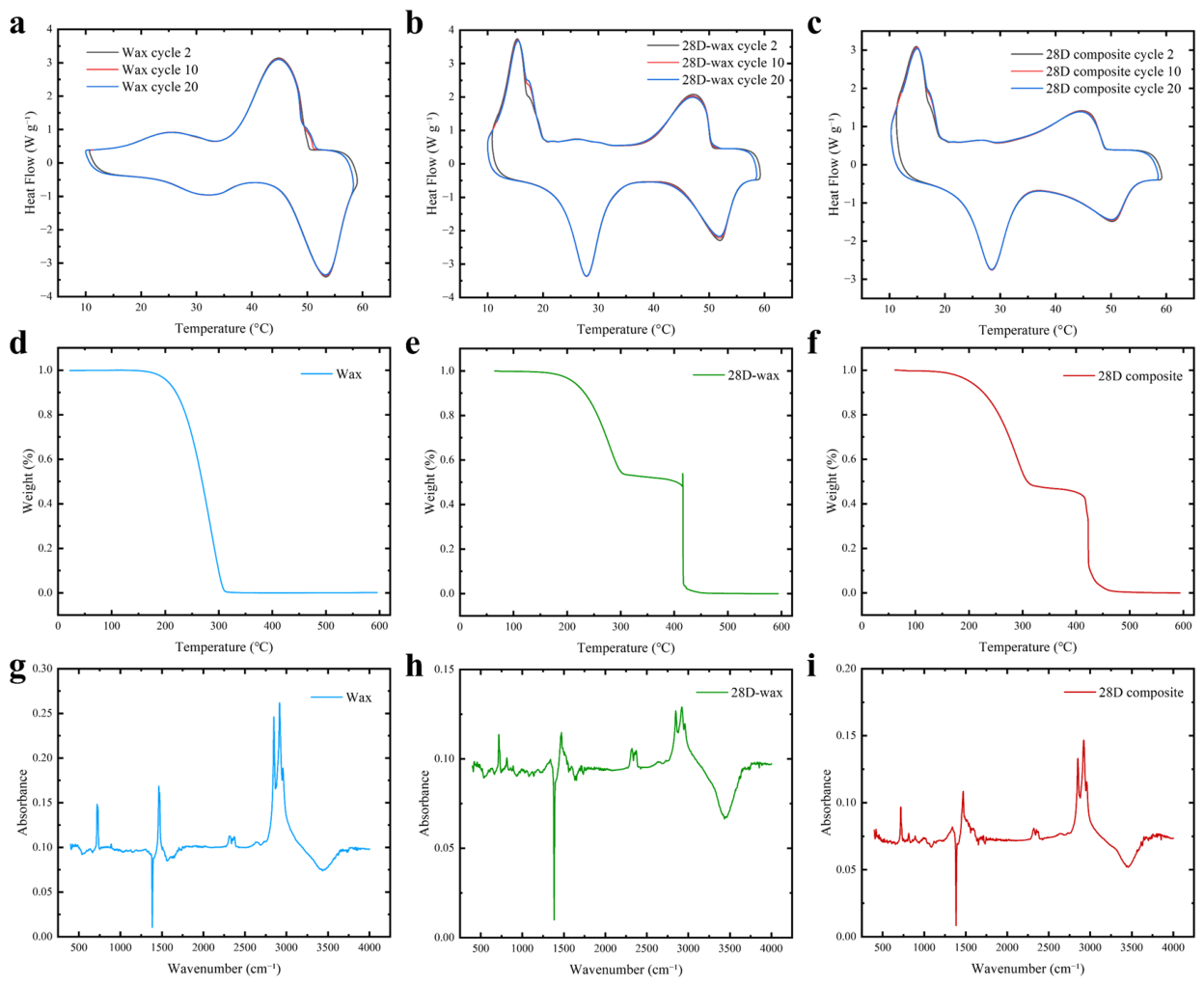
To further verify the phase change behavior and thermal stability of the PCM systems used in this study, differential scanning calorimetry (DSC) and thermogravimetric analysis (TGA) measurements were conducted, as shown in
Figure 4. Three materials were characterized, including paraffin wax, a 28D-wax mixture (60 wt% MicroPCM 28D and 40 wt% paraffin), and the 28D composite containing an additional 2 wt% nano carbon black. For DSC measurements, repeated heating–cooling cycles were performed between 10 °C and 60 °C to evaluate phase change temperature, latent heat, and thermal cycling stability. The DSC curve of paraffin wax (
Figure 4a) exhibits a single phase change peak centered around 45 °C with a melting enthalpy of approximately 185 J g
−1. The nearly overlapping curves for cycles 2, 10, and 20 indicate stable phase change behavior during repeated thermal cycling.
The DSC curves of the 28D-wax mixture and 28D composite are shown in
Figure 4b,c, respectively. Two distinct phase transition peaks are observed for both materials. The low-temperature peak near 28 °C corresponds to the MicroPCM 28D component, consistent with the manufacturer-reported melting temperature, while the higher-temperature peak corresponds to the paraffin wax phase transition. The total melting enthalpy of the 28D-wax mixture is approximately 195–200 J g
−1, indicating that the addition of MicroPCM 28D maintains comparable latent heat storage capacity. After introducing 2 wt% nano carbon black, the melting enthalpy slightly decreases to approximately 175–180 J g
−1, while the phase change temperature remains nearly unchanged. The consistent peak positions and overlapping curves across repeated cycles demonstrate that the composite materials maintain stable phase change behavior and good thermal cycling stability.
The TGA curves of the three materials are presented in
Figure 4d–f. Paraffin wax exhibits single-step thermal decomposition, whereas the 28D-based materials undergo multi-stage degradation due to the presence of microencapsulated PCM and additives. The 28D composite retains a small residual mass after decomposition, which is attributed to the nano carbon black content. These results indicate that the composite PCM systems maintain good thermal stability within the operating temperature range of battery thermal management applications.
For the 28D-wax mixture and the 28D composite (
Figure 4h,i), the major absorption peaks associated with paraffin remain unchanged, indicating that the fundamental chemical structure of the PCM matrix is preserved after mixing. No new characteristic peaks are observed after incorporating MicroPCM 28D and nano carbon black, suggesting that the composite formation is dominated by physical blending rather than chemical reactions. Minor variations in peak intensity are attributed to the presence of microencapsulated PCM particles and nano carbon additives. These results confirm the chemical compatibility of the composite components and support the thermal stability observed in DSC and TGA measurements.
4. Quantitative Performance Comparison
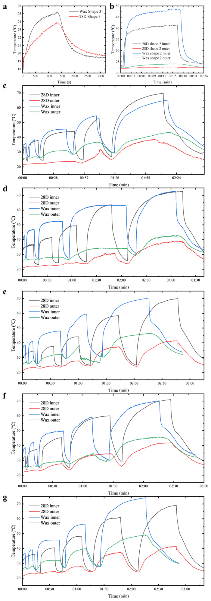
Figure 5 presents the transient temperature evolution of the battery capsules under different airflow conditions and capsule geometries.
Figure 5a shows the infrared temperature evolution measured on the front surface of the capsule for Shape 3, which provides a representative comparison between the two PCM systems. The temperature rise of the 28D composite capsule is lower than that of the wax capsule, indicating a stronger thermal buffering effect during the heating stage.
Figure 5b further compares the inside and outside temperatures of the capsule for Shape 2 under an airflow speed of 5 m·s
−1. The results show that the inside temperature of the capsule is consistently higher than the outside temperature due to the internal heat source. Compared with the wax composite, the 28D composite exhibits a lower inside temperature and a more gradual temperature rise, indicating improved internal heat distribution and enhanced phase change buffering.
Figure 5c–g present the complete transient temperature responses of the five capsule geometries under all airflow conditions. Each subfigure corresponds to a specific capsule shape, where
Figure 4c shows Shape 1,
Figure 4d shows Shape 2,
Figure 4e shows Shape 3,
Figure 4f shows Shape 4, and
Figure 4g shows Shape 5. For each geometry, five distinct temperature peaks can be observed in the inside temperature curves. From left to right, the peaks correspond to airflow speeds of 10, 5, 3, 1, and 0 m·s
−1, respectively. Each airflow condition was tested independently, and the capsule was allowed to cool down to ambient temperature before the next heating cycle was initiated.
Since the experiments for the 28D composite and the wax composite were conducted under slightly different ambient temperatures, a baseline correction was applied to the wax data before comparison. The experiments for the 28D composite were conducted during the daytime with an ambient temperature of approximately 25 °C, while the wax experiments were performed at night with an ambient temperature of approximately 21 °C. To compensate for this difference, the wax temperature data were corrected using
where
and
represent the ambient temperatures during the two experimental sessions. This correction aligns the temperature baselines of the two datasets without altering the temperature evolution trends.
To facilitate comparison between corresponding airflow conditions, minor temporal alignment was also performed. For each airflow segment
, the peak temperature time was identified using the inside thermocouple temperature:
A small portion of the steady-state plateau region near the peak of the 28D curve was adjusted to align the peak positions under identical airflow conditions. This adjustment slightly modifies the duration of the steady-state plateau but does not affect the peak temperature values or the overall heating and cooling trends. Therefore, the comparison of peak temperature and transient thermal behavior remains valid.
The airflow around the capsules corresponds to external crossflow over non-axisymmetric geometries. In this context, the characteristic length is defined as the representative length scale in the direction normal to the incoming airflow. For circular capsules, this length corresponds to the diameter, while for oval capsules, it is approximated by the minor axis, which represents the projected frontal dimension exposed to the airflow. This definition is adopted to provide a consistent geometric basis for comparing different capsule shapes. Accordingly, the present study focuses on experimentally observed trends in convection intensity rather than predictive heat transfer modeling.
Under these convection-dominated conditions, the advantage of the 28D composite becomes more evident. The MicroPCM 28D particles provide distributed latent heat storage throughout the composite, while the uniformly dispersed nano carbon black enhances internal thermal transport. As a result, heat generated inside the capsule can be more effectively redistributed toward the capsule surface, where it can be removed by the external airflow. This effect explains why the temperature reduction of the 28D composite becomes more pronounced at higher airflow speeds.
The capsule geometry also influences the thermal performance under forced convection. The oval capsules (Shapes 1–3) were designed with the major axis aligned with the incoming airflow. Under this configuration, the oval cross sections are more streamlined than circular ones and can delay flow separation and reduce the size of the downstream wake region. Because the thermocouples were positioned on the downstream side of the capsule, the local temperature response is strongly influenced by the wake development behind the capsule. A smaller wake region generally enhances the convective heat transfer on the backside surface. This trend is also related to the capsule aspect ratio, where elongated geometries with higher aspect ratios tend to produce smaller wake regions and improve heat removal, resulting in lower peak temperatures.
The oval shapes can be characterized by the aspect ratio defined as the ratio between the major and minor axes. The aspect ratios are approximately 1.272, 1.180, and 1.094 for Shapes 1, 2, and 3, respectively, gradually approaching the circular case. Because the minor axes of the oval capsules are close to the diameters of the circular capsules, the frontal blockage differences are relatively small. Therefore, geometry dependent thermal behavior is mainly associated with differences in flow separation and wake behavior rather than large variations in flow conditions.
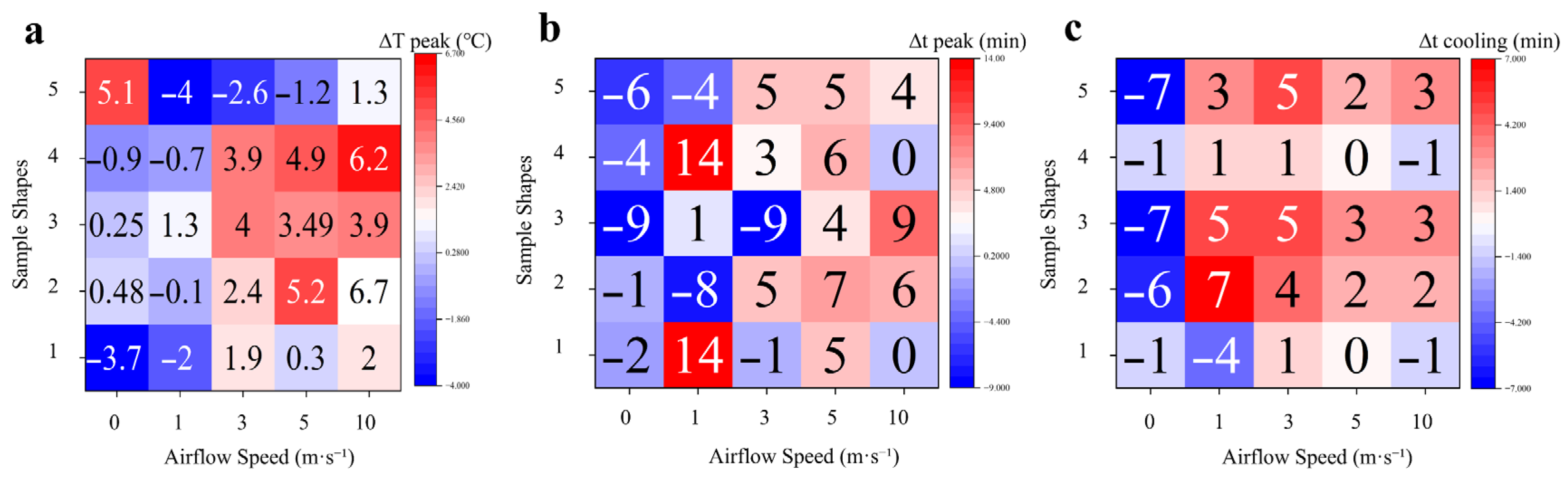
To quantitatively compare the thermal performance of the two PCM systems, three evaluation metrics were defined based on the temperature curves. The peak temperature difference is defined as
where
is the maximum temperature measured for the wax composite capsule, and
is the maximum temperature measured for the 28D composite capsule. A positive value of
indicates that the 28D composite achieves a lower peak temperature than the wax composite.
The delay in reaching the peak temperature is defined as
where
and
represent the times required for the 28D composite and wax composite capsules to reach their respective peak temperatures. A positive value of
indicates that the 28D composite maintains the phase change buffering process for a longer duration before reaching the steady state peak temperature.
The difference in cooling duration is defined as
where
and
represent the times required for the 28D composite and wax composite capsules to cool down to near the ambient temperature after the heating power is turned off. Therefore, the positive value of
indicates that the 28D composite releases heat more slowly during the cooling stage.
The quantitative comparison across all capsule geometries and airflow conditions is summarized in
Figure 6. Overall, the 28D composite shows lower peak temperatures, delayed peak occurrence, and longer cooling durations compared with conventional wax, particularly under strong forced convection.
Figure 6a shows the peak temperature differences between the two PCM systems. Positive values dominate at higher airflow speeds, indicating that the 28D composite generally achieves lower peak temperatures under strong forced convection.
Figure 6b presents the delay in reaching the peak temperature, which is mostly positive across different geometries and airflow conditions. This result suggests that the MicroPCM-based composite can extend the effective thermal buffering period.
Figure 6c compares the cooling durations, where positive values indicate slower heat release for the 28D composite. The longer cooling duration reflects the enhanced latent heat storage capability of the MicroPCM 28D particles as well as the higher viscosity of the composite matrix.
In addition to improving short term thermal buffering, the MicroPCM 28D suspension also enhances the long-term stability of the composite system. The high viscosity of the 28D composite prevents nano carbon black particles from sedimentation during repeated heating and cooling cycles. In contrast, nano additives in conventional paraffin systems are more susceptible to long-term sedimentation, which can gradually degrade the uniformity of thermal conductivity within the capsule. As a result, the 28D composite is expected to maintain more stable thermal performance over extended operating periods.
5. Conclusions
This study investigated the thermal regulation performance of MicroPCM-based composite capsules for battery thermal management under different airflow conditions and capsule geometries. A sedimentation-stable composite consisting of 60 wt% MicroPCM 28D, 40 wt% paraffin wax, and an additional 2 wt% nano carbon black was developed and compared with a conventional wax-based composite system. Five capsule geometries were fabricated using fused filament fabrication 3D printing with Onyx material, including three oval shapes and two circular shapes, to examine the influence of geometry on convective heat dissipation.
Infrared thermography and wind tunnel experiments were conducted to characterize the transient thermal behavior of the capsules. The results show that the thermal response of the capsule system can be divided into three stages: sensible heating, phase change buffering, and cooling after power removal. The MicroPCM-based composite exhibited improved internal heat redistribution and stronger phase change buffering compared with the wax composite. Under low airflow conditions (0–1 m·s−1), the heat transfer process was dominated by conduction, and the temperature difference between the two composite systems was relatively small. As the airflow increased to 3–10 m·s−1, forced convection became the dominant heat transfer mechanism, and the advantage of the 28D composite became increasingly evident.
Quantitative performance analysis based on peak temperature difference, peak delay time, and cooling duration demonstrates that the MicroPCM 28D composite generally achieves lower peak temperatures and longer thermal buffering durations under moderate and strong convection conditions. The results also show that capsule geometry influences the thermal performance through its interaction with external airflow. Oval capsules with the major axis aligned with the incoming flow modify the flow separation and wake development near the downstream surface, which improves convective heat dissipation compared with circular geometries.
In addition to improved thermal regulation performance, the MicroPCM-based composite also provides enhanced long-term material stability. The high viscosity of the MicroPCM 28D suspension suppresses the sedimentation of nano carbon black particles during repeated melting and solidification cycles, ensuring a more uniform thermal conductivity distribution within the composite. This property addresses one of the major limitations of conventional paraffin-based nanocomposites.
Overall, the results demonstrate that the combination of MicroPCM-based composite materials and geometry-regulated capsule design provides an effective strategy for improving passive thermal management of battery systems. The findings provide useful design guidelines for future phase change thermal management structures in battery modules and other energy storage applications.