1. Introduction
1.1. Motivation
Microgrids (MGs) are experiencing a big development in the traditional electricity system [
1]. MCs are a solution only for a limited area [
2]. MGs integrate different green energies, energy storage systems (ESSs), and loads [
3,
4,
5,
6]. All types of renewable energy, like photovoltaics (PV), biomass, hydro, tidal, and wind turbines, are used for the production of clean electrical energy. These energy sources can be connected to an MG through the use of different power converters and inverters [
7,
8,
9]. They can respond to the peak demand for energy. MCs can be connected to a grid, islanded, or hybrid system. The connected-to-grid system is connected to the main grid and can also exchange power as needed. In an islanded area, MCs function separately from the main grid, applying renewable energy and storage systems and distributing power locally [
10].
An MG is hard to control due to its use of different sources, ESSs, and different load types, such as direct current (DC) or alternating current (AC). To ensure the regulation of MGs, a controller requirement should be added. The electronic power-based converters and inverters make the MGs more flexible in their control [
11]. Energy management system (EMS) use in MGs is of interest in order to facilitate energy storage systems. EMSs enable the implementation of ESS devices if there is a need for power and respond to the need for energy using ESS excesses of energy [
12]. The existing methodologies used in EMSs of MGs are based on linear and non-linear programming methodologies. They employ centralized controller systems and linear or non-linear programming techniques, where heuristics and meta-heuristics are largely used in the EMSs of MGs [
13].
For validation, resilient control, and function in power systems under extreme meteorological variations, the control strategy becomes a self-healing smart distribution system [
14,
15,
16]. As one of the most popular control and energy distribution methodologies, a multi-agent system (MAS) is implemented to ensure the good control of energy between different devices [
17,
18]. MASs are represented with different agents and a monitor system, where the interconnection is ensured by undirected or directed contributions [
19,
20].
1.2. Literature Review
Studies performed on MAS applications have been carried out across wide areas and in different management systems, such as the plans for distributed generators and static/mobile ESSs [
21], descriptor systems to ensure a strong leader-following output consensus [
22], the distributed management of MGs implemented in JADE [
23], the energy management and optimization of MG clusters [
24], the controlled charging of a large population of electric vehicles [
25], etc.
Fuzzy logic systems (FLSs) have been widely implemented to distribute energy for MASs [
26]. FLSs are already used in different applications, such as in the energy management of batteries and supercapacitors for PV storage in order to eliminate the peak current [
27], in robust stability analysis and systematic design [
28], in the decentralized voltage control of power systems with a proposition of a smart self-healing method [
29,
30,
31], etc.
1.3. Contribution and Paper Organization
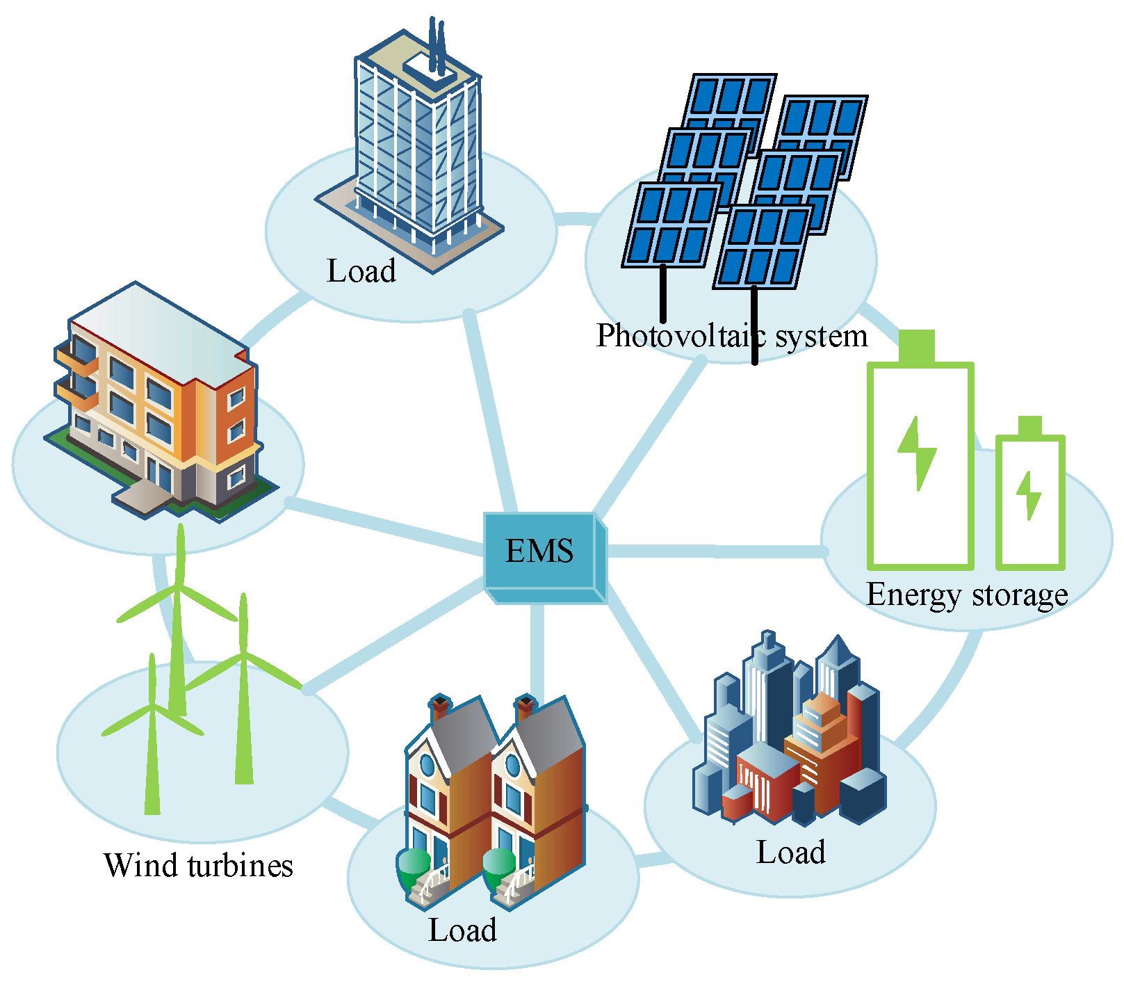
This paper presents an MG that uses PV and wind as principal energy sources. The global presentation of this MG is given in
Figure 1. The ESS is powered by batteries. In order to do no damage to the batteries, they are designed in three packs. Supercapacitors (SCs) are used in order to reduce the power fluctuations caused by meteorological changes in solar irradiation and temperature on the PV power system and the influence of wind speed on the wind energy power system.
The control system and the distribution of energy of the whole system are based on the MAS using FLS control. This distribution of energy between packs reduces the stress on batteries. To not damage any of the batteries together by the charge and discharge cycles, one pack of batteries can usually be used. When this pack of batteries is fully discharged and there is a need for energy, it can be taken from another pack of batteries. The same analysis applies to the charge: when batteries of the first pack are fully charged and there is an excess of energy, it can be stored in another pack of batteries.
The rest of this paper is organized under the following headings.
Section 2 presents the system description.
Section 3 is reserved for the multi-agent system for voltage regulation. Simulation results and validations are given in
Section 4.
Section 5 presents a conclusion to this study.
2. System Description
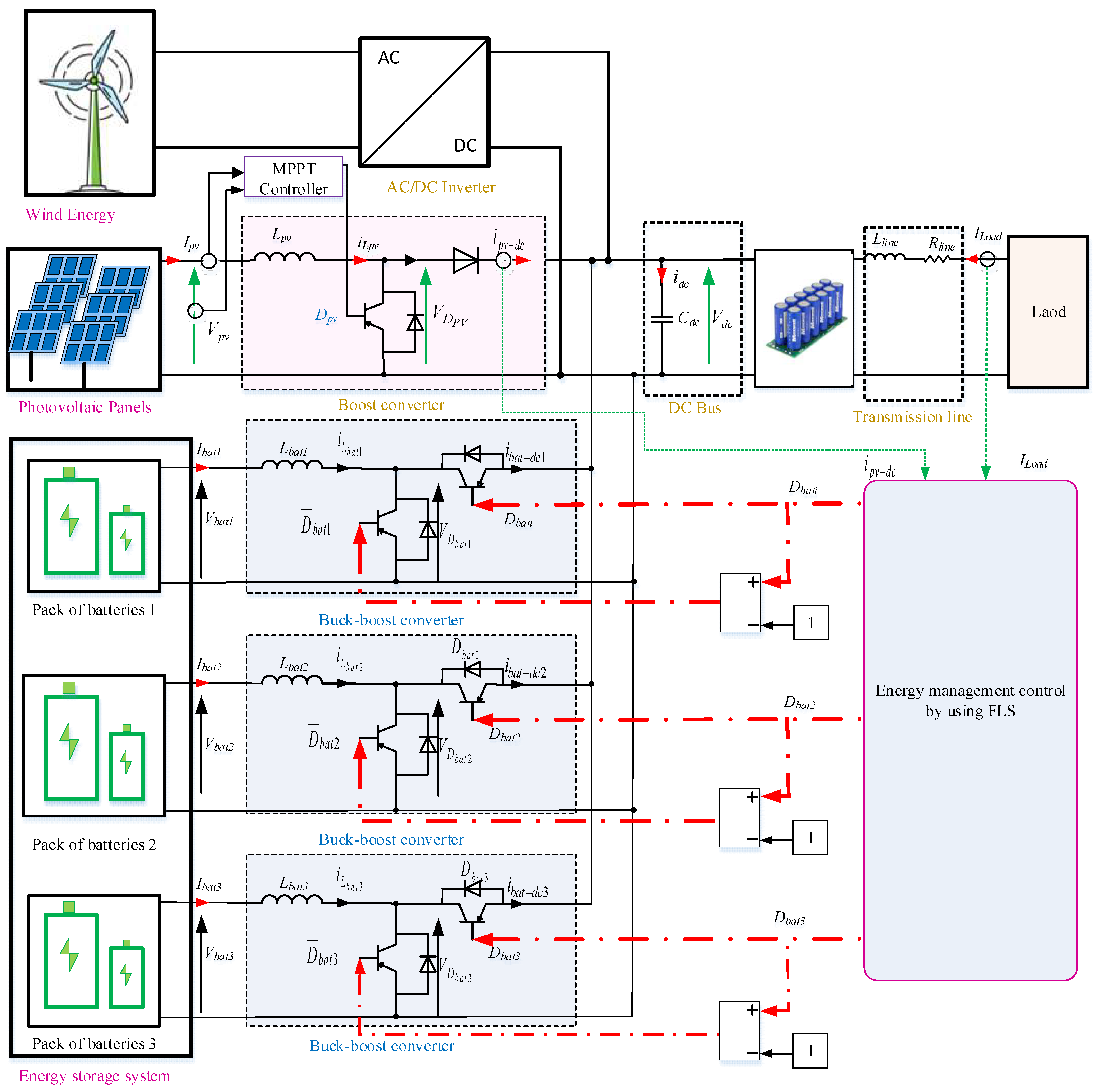
The used configuration is the semi-active topology, given in
Figure 2. The proposed system presented is a renewable energy system composed of PV panels and wind energy as the principal hybrid energy sources. The energy storage is powered by batteries. The objective of the use of batteries is to meet the fluctuations of solar irradiation and wind changes. The storage system is divided into three packs of batteries. The distribution of energy between packs reduces the stress on batteries. To avoid damaging any of the batteries together by the charge and discharge cycles, one pack of batteries can usually be used. When this pack of batteries is fully discharged and there is a need for energy, it can be taken from another pack of batteries. The same analysis applies to the charge: when batteries of the first pack are fully charged and there is an excess of energy, it can be stored in another pack of batteries.
The proposed configuration for this study implements different buck–boost converters in parallel with batteries. SCs are implemented in parallel to the loads and sources (PV and wind). In this case, SCs are considered to be low-pass filters. The main advantages of this configuration are that it uses converters just for batteries, and there is no need for converters for SCs.
SCs are used in parallel to the load, PV, wind, and batteries in order to reduce the power fluctuations. These fluctuations are caused by the change in the load demand, the influence of the change in the solar irradiation and temperature on the PV system, and the influence of the wind speed on the wind energy system. Also, the implementation of four converters causes a lot of fluctuation. The main objective of the choice of SCs is that they be characterized by a high power density. SCs reply so quickly to energy needs and absorb excesses of energy. That makes it the most adaptive device for power smoothing.
SCs are also characterized by a long lifespan, and they can work in different temperatures.
The ESS is divided into three packs of batteries. The distribution of energy is shown in
Figure 3. The DC bus voltage is 400 V. In order to avoid perturbations in the DC bus voltage, where the output voltage of all devices should be 400 V, the load power is 50 kW. SCs are implemented for power smoothing; for this, the maximum power is limited to 50 kW. The PV and wind systems are chosen to be 50 kW and 1.5 M, respectively. The power of the storage system is chosen to be 2.1 MW and is divided into three packs of batteries. Each battery pack is powered by 700 kW. The objective of this distribution of energy between packs is to reduce the stress on the batteries. To avoid damaging any of the batteries together by the charge and discharge cycles, one pack of batteries can usually be used. When this pack of batteries is fully discharged and there is a need for energy, it can be taken from another pack of batteries. The same analysis applies to the charge: when the first pack of batteries is fully charged and there is an excess of energy, it can be stored in another pack of batteries. The control system is proposed by an MAS, where the distribution of energy between different devices is facilitated by FLS.
3. MAS for Voltage Regulation
3.1. Presentation of MAS
The regulation and analysis methodology are proposed using MAS control. This proposed method will stabilize the bus voltage at 400 V by giving an intelligent distribution of energy between different devices.
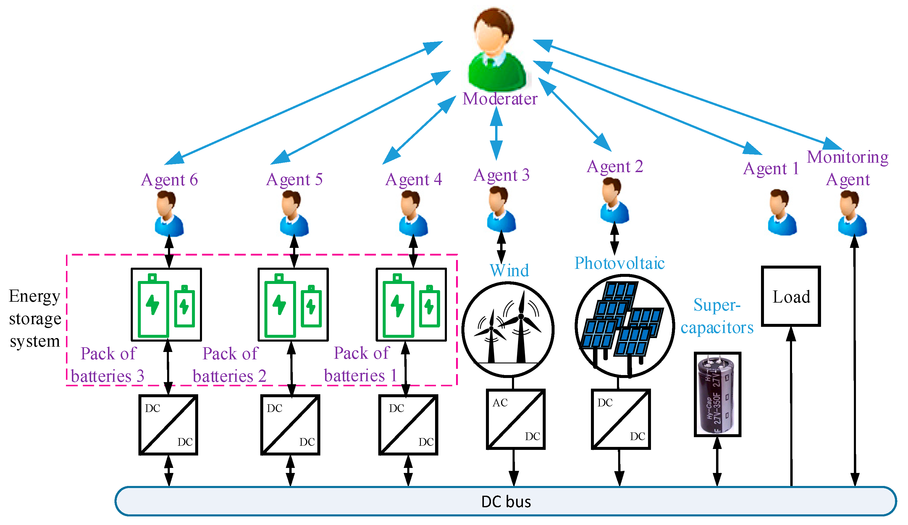
Figure 4 shows the basic structure of the MAS platform.
There are three types of agents: agents, monitoring agents, and the moderator.
There are six agents: battery 1, battery 2, battery 3, the wind system, the PV system, and the load.
Monitoring agents represent the DC bus. These are the principal agents that give information about the whole system.
The moderator coordinates the regulation and control of the system. It is given by an FLS that controls the system depending on the state of different devices and the need for energy.
These agents’ moderator can transmit warnings to the monitoring agents if voltage disturbances occur and can request voltage compensation to stabilize the Vdc. The main objective of the moderator is to minimize the leakage power.
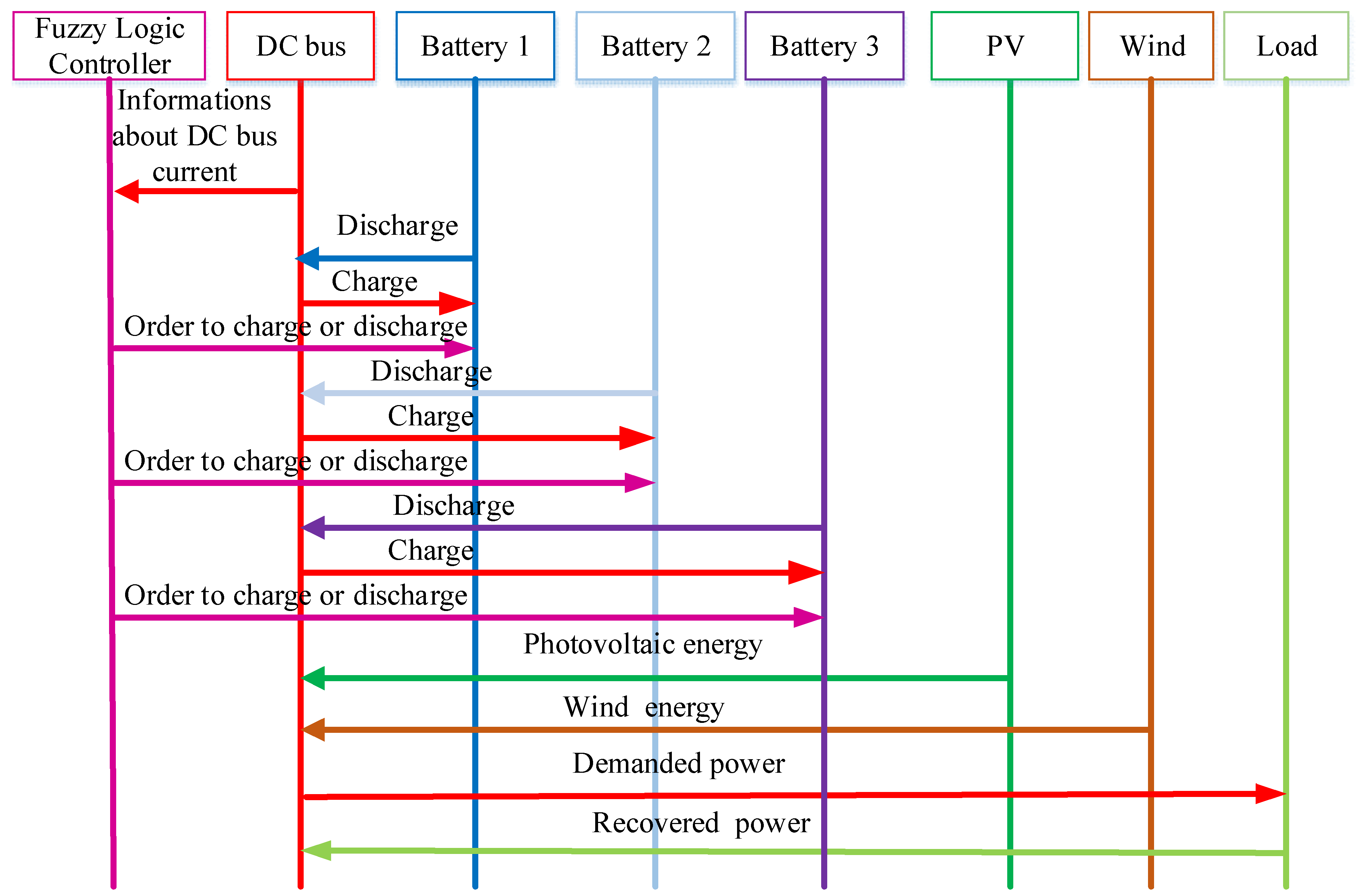
Figure 5 presents the communication between the different agents. The DC bus receives energy from PV panels, the wind system, and the load. The three packs of batteries receive energy from the DC bus for storage and give energy to the DC bus where there is a need for energy. SCs charge from the DC bus and discharge into the DC bus in order to smooth the power. The FLS plays the role of the controller by giving orders to different buck–boost converters to charge or discharge the batteries. The FLS takes information from the DC bus in order to make decisions.
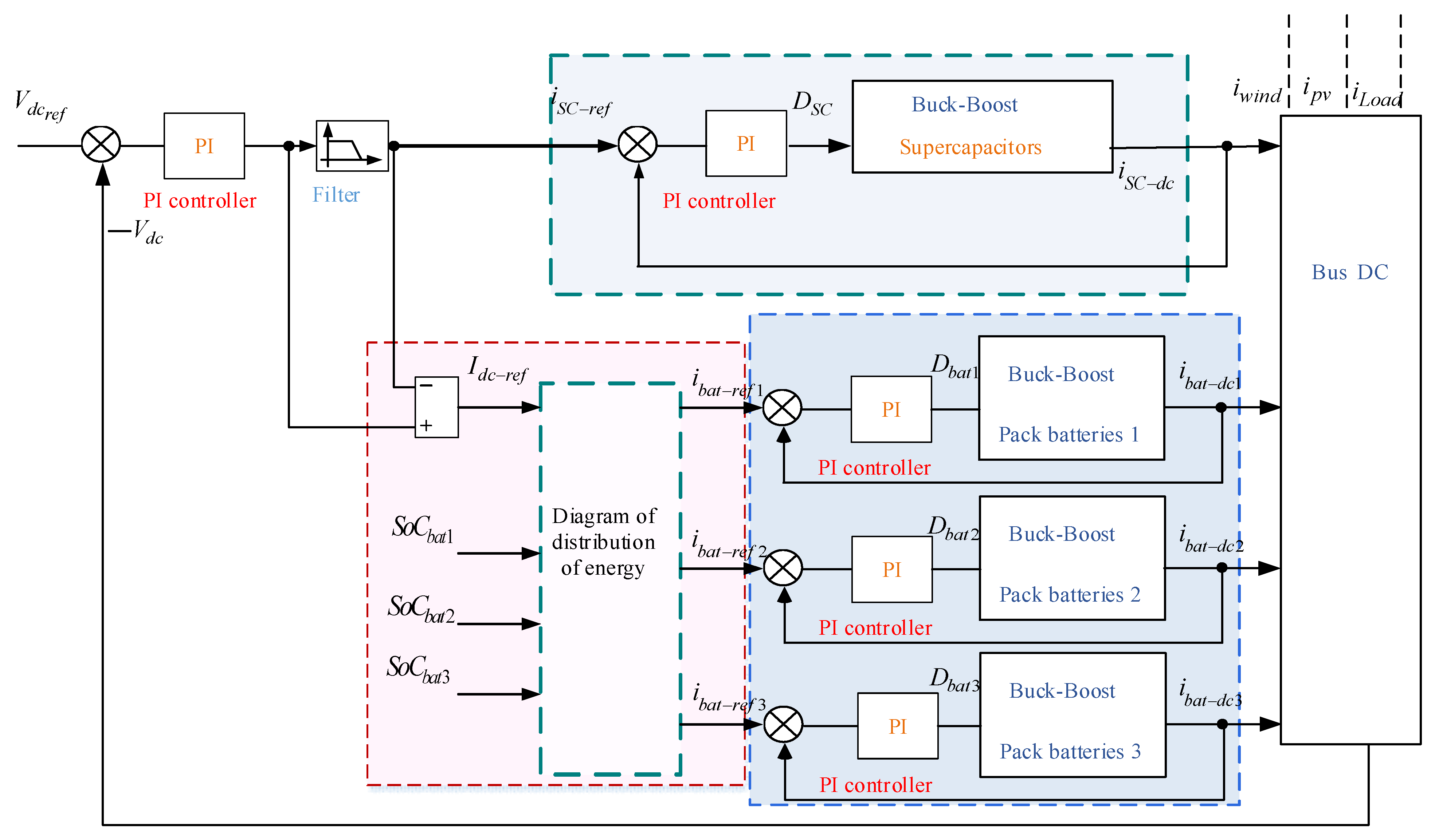
3.2. DC Bus Control
The control of the DC bus voltage is represented in
Figure 6. The voltage is fixed at 400 V. This strategy is represented with proportional–integral (PI) controllers. A PI controller is implemented to calculate the DC bus current. It is filtered using a low-pass filter, where its output is the SC’s reference current. The difference between the DC bus current and the reference current of SCs is the reference current of the three packs of batteries.
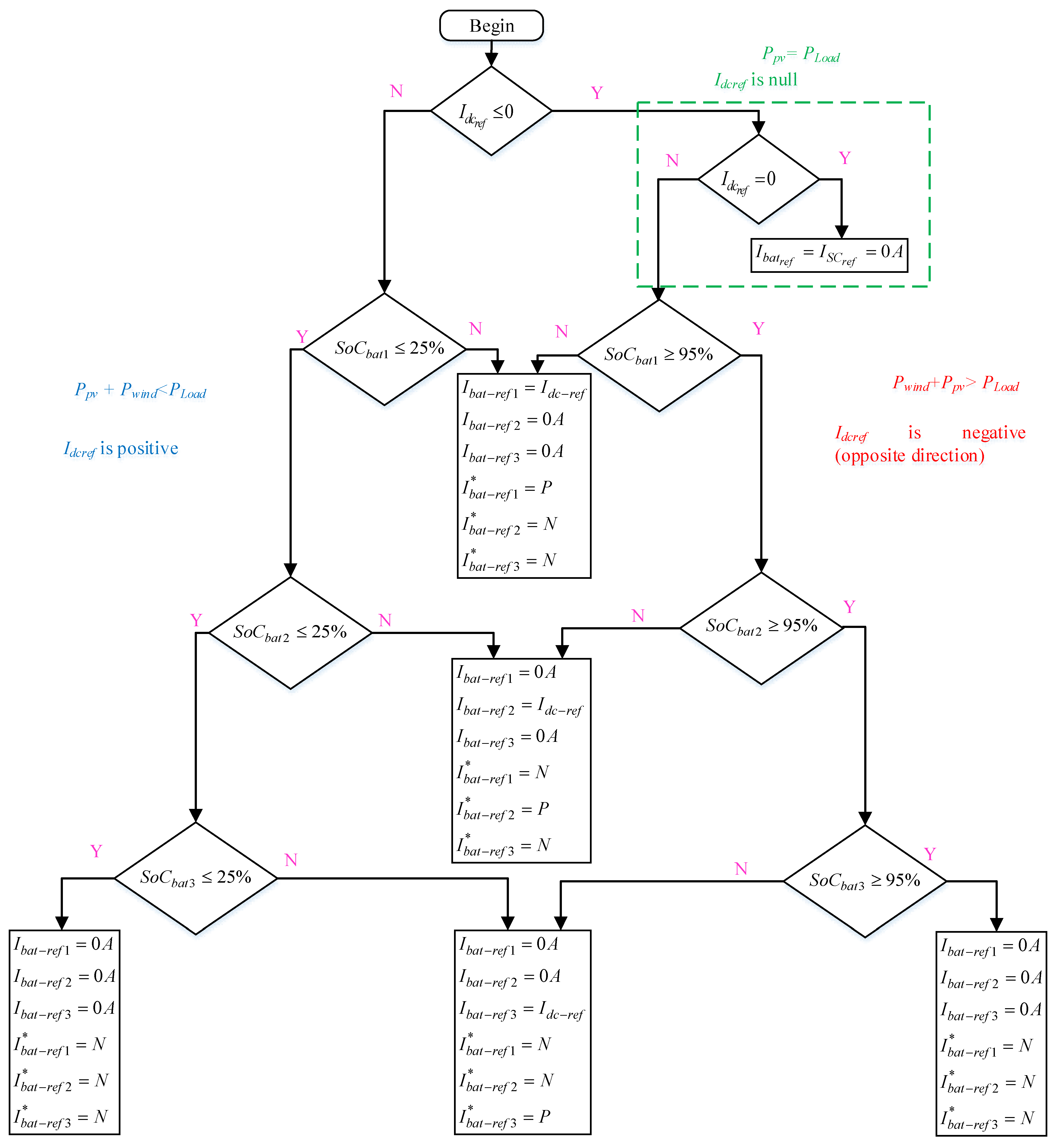
An energy management strategy (EMS) is implemented to provide the reference current of the three packs of batteries. This EMS is based on the flowchart given in
Figure 7.
The inputs of the EMS are the reference current of the DC bus (
Vdcref) and the state of charge of the batteries of the first pack (
SoCbat1), the second pack (
SoCbat2), and the third pack (
SoCbat3). The outputs of the EMS are the reference current of the first pack of batteries
ibat-ref1, the second pack
ibat-ref2, and the third pack
ibat-ref3. The following equation describes the behavior of the DC bus:
The EMS is based on the outputs of the three switches, where is the control of the first switch, is the control of the second switch, and is the control of the third switch. The analysis of the EMS is presented as follows:
If Idc-ref is negative , and then and .
If Idc-ref is negative , and then and
If Idc-ref is negative and then and
If Idc-ref is negative and then , and
If Idc-ref is positive , and then and
If Idc-ref is positive , and then and
If Idc-ref is positive and then and
If Idc-ref is positive and then and
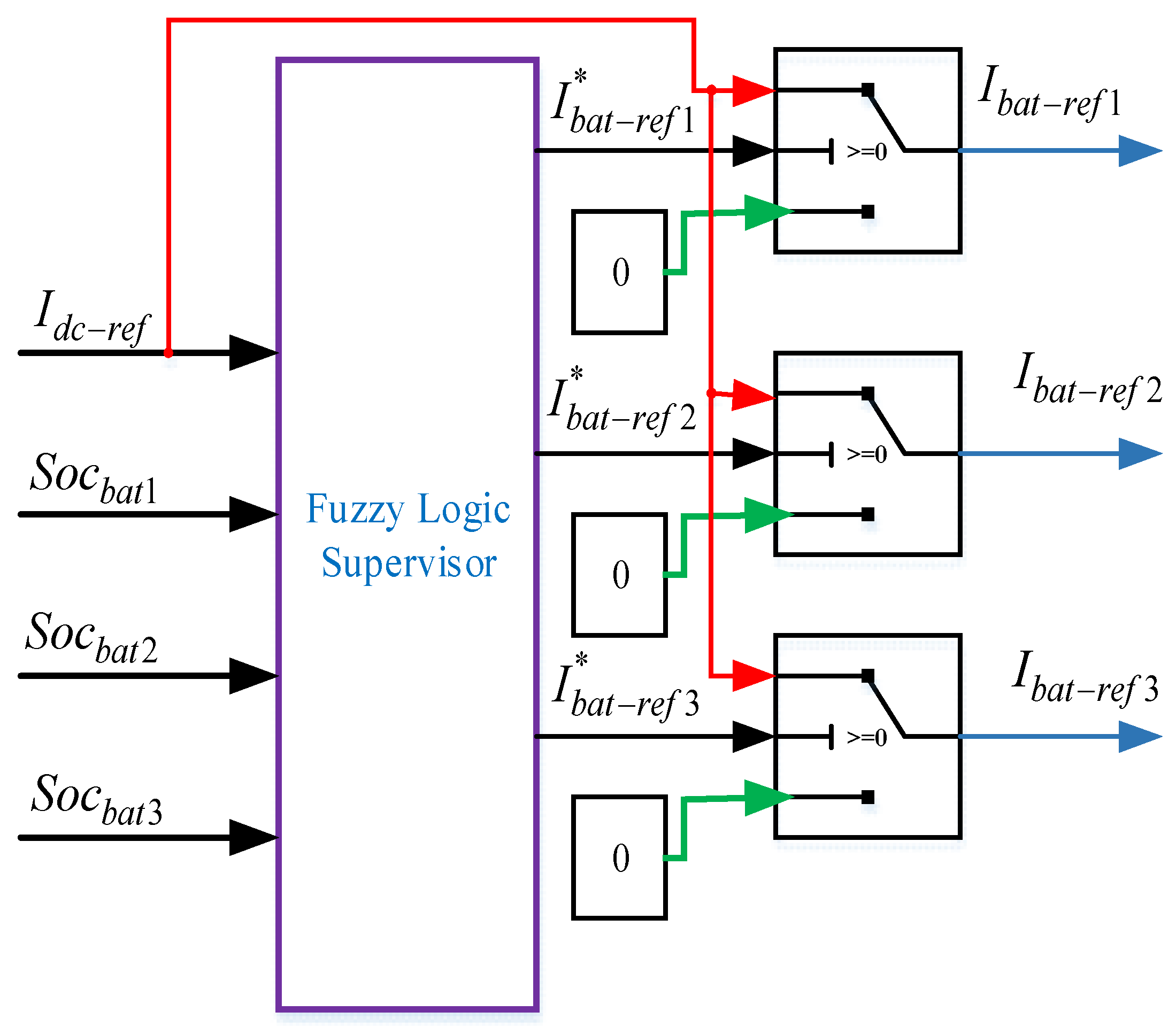
3.3. FLS Management System
The main objective of the use of FLS in this system is to control the overall system according to the excess of or the need for energy and the SoC of batteries. The reference currents of different batteries are represented according to the principle shown in
Figure 8.
This system is composed of three switches that choose between 0 and . The inputs of the FLS are the reference current of the DC bus and the SoCs of batteries 1, 2, and 3: , , and , respectively. The outputs are the control of the three switches , , and . The outputs of the three switches are the DC bus currents of the first pack of batteries Ibat-dc1, the second pack of batteries Ibat-dc2, and the third pack of batteries Ibat-dc3.
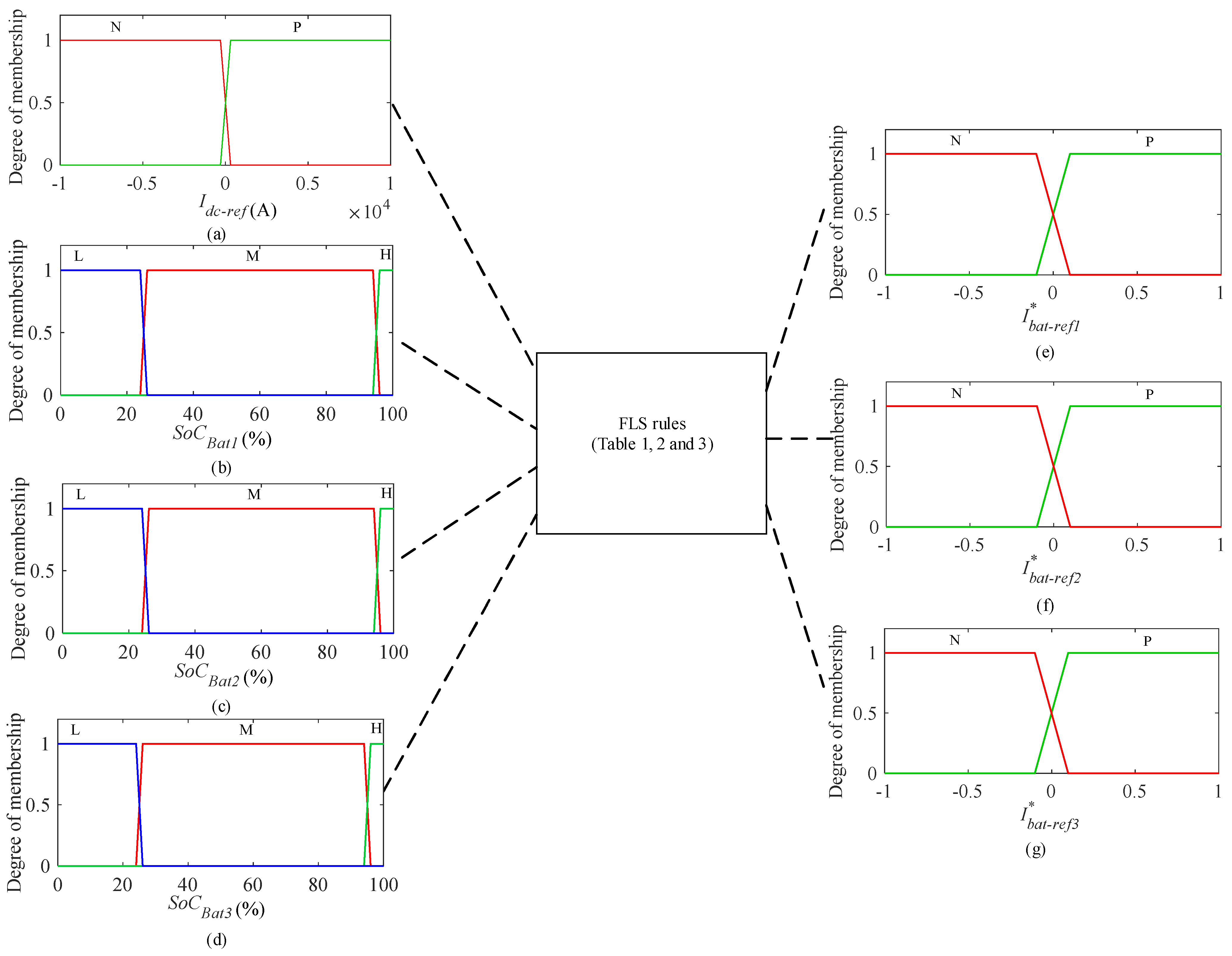
The aim of this study is to find the membership functions that relate the inputs to the outputs.
Figure 9 represents the inputs and outputs memberships, reactively.
The membership function of the reference current of the DC bus is presented between −1000 A and 1000 A. It is shown in
Figure 9a. This current is represented with two levels: N represents negative current, and P represents positive current. Also, N represents the need for charge, and P represents the discharge of the batteries.
The SoCs of batteries are represented between 0% and 100%. These SoCs are represented by three levels:
- -
L represents the low level (between 0% and 25%).
- -
M represents the medium level (between 25% and 95%).
- -
H represents the high level (between 95% and 100%).
The output membership functions are shown in
Figure 9, which represent the command of the three switches. N represents negative, and P represents positive. The output membership functions are estimated between −1 and 1. For −1, it can choose
, and for 1, it can choose 0.
The FLS rules used for the distribution of energy for battery packs are given by the analysis of the input and output systems. These rules are divided into 54 parts. The laws depend on the control strategy.
The control rules that associate the fuzzy input with the output are divided into three tables, which are the following:
Table 1 represents the fuzzy logic rules used between
,
,
, and
, to command switch 1 by
.
The command of switch 2
is represented in
Table 2, which is used between
,
,
, and
.
Table 3 represents the fuzzy logic rules used between
,
,
, and
to command switch 3 by
.
4. Simulation Results and Validation
Two simulation tests are proposed to prove the performance of the presented EMS, control system, and the effectiveness of the use of SCs in MGs. These simulation results are built with the MATLAB/Simulink environment. The two tests are proposed with the same parameter values, and these are given in
Table 4.
These parameters are chosen in order to verify the switch from pack battery 1 to pack battery 2, and this was carried out for 60 s. The first simulation test is proposed without SCs, and the second is proposed with SCs.
The two simulation tests have been represented with the same variation in PV, load, and wind current. The PV current is 200 A, the wind current is between 800 A and 2900 A, and the load current is between 700 A and 500 A.
4.1. Simulation Results of a Hybrid MG Without SCs
The first simulation test is represented without SCs. The proposed load current, PV current, and wind current are given in
Figure 10a. The currents of the first and second packs of batteries are represented in
Figure 10b and c, respectively. The SoCs of the first and second packs of batteries are given in
Figure 10d and e, respectively. When the SoC of the batteries of the first pack is 25%, they stop discharging, and the batteries of the second pack fulfill the need for current. The DC bus voltage is shown in
Figure 11f; it represents fluctuation in every change in wind, PV, and load current.
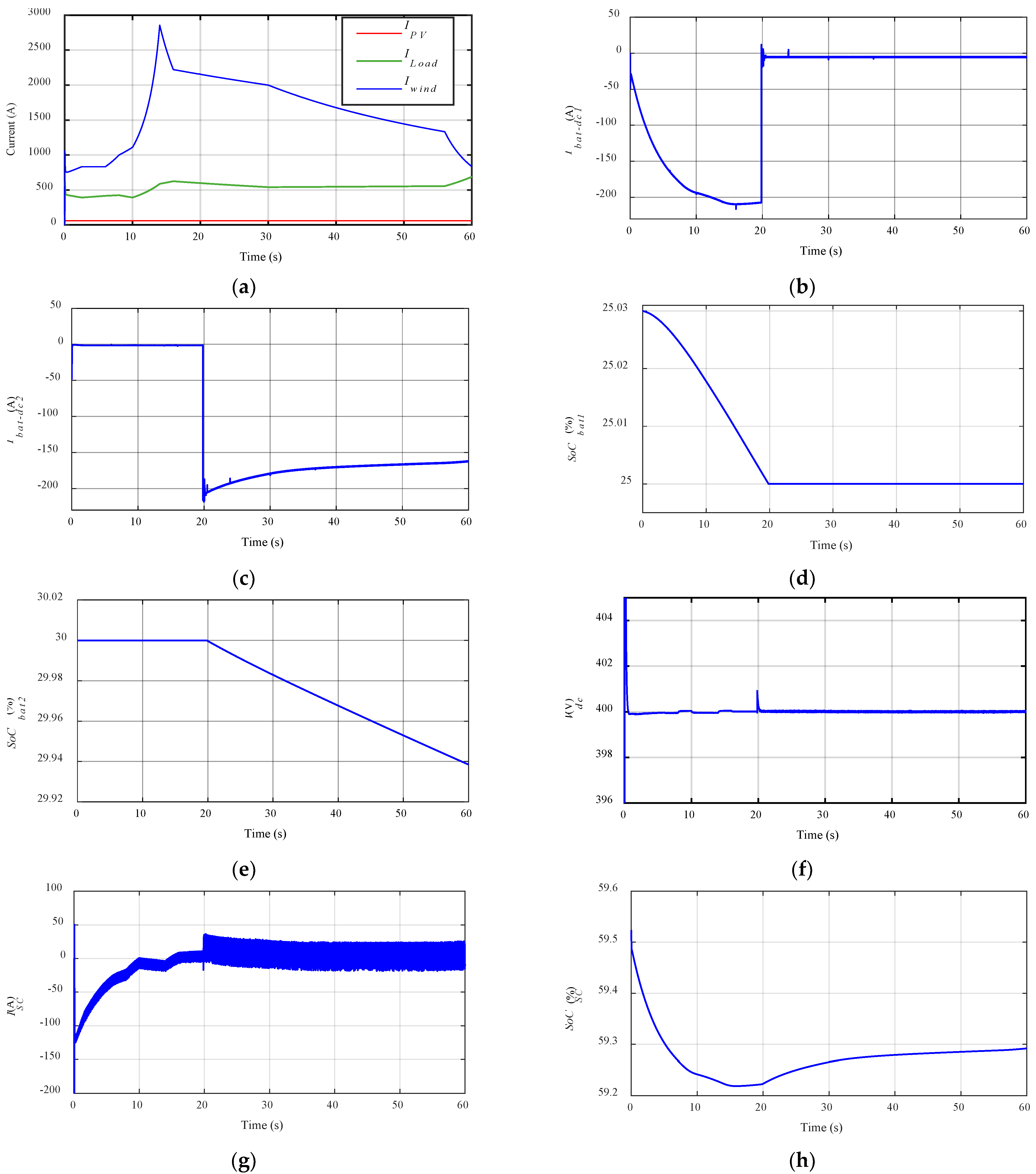
4.2. Simulation Results of a Hybrid MG with SCs
The second simulation test is proposed with the implementation of SCs in parallel to the loads and sources. The objective of the use of SCs is to reduce the power fluctuations. The proposed load current, PV current, and wind current are given in
Figure 11a. The currents of the batteries of the first and second packs are presented in
Figure 11b,c, respectively. The SoCs of the batteries of the first and second packs are presented in
Figure 11d,e, respectively. When the SoCs of the batteries of the first pack are 25%, they stop discharging, and the batteries of the second pack fulfill the need for current. The DC bus voltage is shown in
Figure 11f; it represents fluctuations in every change in wind, PV, and load current. The SC current is given in
Figure 11g, which represents fluctuations. The SoC of SCs is given in
Figure 11h, which represents a high discharge at the start.
4.3. Syntheses
The proposed simulation tests prove the performance of the presented EMS and control system and the effectiveness of the use of SCs in an MG. The use of an MAS based on a fuzzy logic controller gives good results in the distribution of energy between devices. It demonstrates that the proposed EMS can respond to load variation. An MAS offers several advantages for MG control and management. These include improved flexibility, scalability, and reliability compared to traditional centralized control systems. MASs permit distributed decision-making, enabling agents to adapt to varying conditions and optimize their performance in real time. The disadvantage of MASs is their complexity in development and implementation, where control can be difficult and which require the careful design of agent behaviors, communication protocols, and control strategies.
These tests prove that the proposed model and EMS give good results. When the SoC of the batteries of the first pack is 25%, they stop discharging, and the second pack of batteries starts discharging. The use of SCs for power smoothing gives good results. However, it makes the Vdc constant at 400 V without any fluctuations. The effect of the change in the PV, batteries, and load current on battery packs 1 and 2 is reduced using SCs in parallel with the loads and different sources.
5. Conclusions
The EMS for an MG based on PV and wind systems as its main energy sources was presented in this paper. The energy storage is powered by batteries, which are divided into three packs in order to prevent damage to all batteries at the same time. Power smoothing is ensured by the introduction of SCs in parallel to the loads and sources. The use of SCs reduces the power fluctuations caused by the changes in solar irradiation and temperature on the PV system and the influence of the wind speed on the wind energy system. The EMS of the whole system is implemented using an MAS. The distribution and the control of the proposed MG are ensured by FLS. This EMS distributes energy between the sources and the three batteries according to their SoC. Two simulation results are used to prove the efficiency of the proposed energy management. These simulation tests are proposed with and without SCs. These tests prove that the proposed control strategy gives good results and that the use of SCs reduces power fluctuations. Future work will focus on an AC microgrid protection based on an MAS that requires real-time performance, real-world testing, cybersecurity threat mitigation, and cost reduction.
Author Contributions
Conceptualization, Z.C.; methodology, Z.C.; software, Z.C.; validation, Z.C. and M.O.; formal analysis, S.H.L.; writing—original draft preparation, Z.C.; writing—review and editing, D.C.; visualization, Z.C.; supervision, S.H.L.; project administration, S.H.L. All authors have read and agreed to the published version of the manuscript.
Funding
This work was supported by the Basic Science Research Program through the National Research Foundation of Korea (NRF) and funded by the Ministry of Education (2022R1C1C1005975).
Data Availability Statement
The original contributions presented in this study are included in the article. Further inquiries can be directed to the corresponding author.
Conflicts of Interest
The authors declare no conflict of interest.
References
- Marquez, J.J.; Zafra-Cabeza, A.; Bordons, C.; Ridao, M.A. A fault detection and reconfiguration approach for MPC-based energy management in an experimental microgrid. Control Eng. Pract. 2021, 107, 104695. [Google Scholar] [CrossRef]
- Shahzad, S.; Abbasi, A.A.; Ali, H.; Iqbal, M.; Munir, R.; Kilic, H. Possibilities, Challenges, and Future Opportunities of Microgrids: A Review. Sustainability 2023, 15, 6366. [Google Scholar] [CrossRef]
- López-Prado, J.L.; Vélez, J.I.; Garcia-Llinás, G.A. Reliability Evaluation in Distribution Networks with Microgrids: Review and Classification of the Literature. Energies 2020, 23, 6189. [Google Scholar] [CrossRef]
- Rebollal, D.; Carpintero-Rentería, M.; Santos-Martín, D.; Chinchilla, M. Microgrid and Distributed Energy Resources Standards and Guidelines Review: Grid Connection and Operation Technical Requirements. Energies 2021, 14, 523. [Google Scholar] [CrossRef]
- Guo, F.; Wen, C.; Mao, J.; Song, Y.D. Distributed Secondary Voltage and Frequency Restoration Control of Droop-Controlled Inverter-Based Microgrids. IEEE Trans. Ind. Electron. 2014, 62, 4355–4364. [Google Scholar] [CrossRef]
- Blaabjerg, F.; Teodorescu, R.; Liserre, M.; Timbus, A.V. Overview of control and grid synchronization for distributed power generation systems. IEEE Trans. Ind. Electron. 2006, 53, 1398–1405. [Google Scholar] [CrossRef]
- Shafiee, Q.; Stefanovic, C.; Dragicevic, T.; Popovski, P.; Vasquez, J.C.; Guerrero, J.M. Robust networked control scheme for distributed secondary control of islanded microgrids. IEEE Trans. Ind. Electron. 2014, 61, 5363–5374. [Google Scholar] [CrossRef]
- Yu, W.; Wen, G.; Yu, X.; Wu, Z.; Lu, J. Bridging the gap between complex networks and smart grids. J. Control Decis. 2014, 1, 102–114. [Google Scholar] [CrossRef]
- Olivares, D.E.; Mehrizi-Sani, A.; Etemadi, A.H.; Canizares, C.A.; Iravani, R.; Kazerani, M.; Hajimiragha, A.H.; Gomis-Bellmunt, O.; Saeedifard, M.; Palma-Behnke, R.; et al. Trends in microgrid control. IEEE Trans. Smart Grid 2014, 5, 1905–1919. [Google Scholar] [CrossRef]
- Cabrane, Z.; Ouassaid, M.; Maaroufi, M. Performance enhancement of Solar Vehicle by integration of supercapacitors in the energy storage system. In Proceedings of the IEEE International Renewable and Sustainable Energy Conference (IRSEC), Marrakech, Morocco, 14 November 2016; pp. 62–67. [Google Scholar]
- Fan, B.; Peng, J.; Duan, J.; Yang, Q.; Liu, W. Distributed Control of Multiple-Bus Microgrid With Paralleled Distributed Generators. IEEE/CAA J. Autom. Sin. 2019, 6, 676–684. [Google Scholar] [CrossRef]
- Wang, Z.; Chen, B.; Wang, J.; Chen, C. Networked microgrids for self-healing power systems. IEEE Trans. Smart Grid 2016, 7, 310–319. [Google Scholar] [CrossRef]
- Eiymaya, S.E.; Altin, N. Review of Energy Management Systems in Microgrids. Appl. Sci. 2024, 14, 1249. [Google Scholar] [CrossRef]
- Huang, Y.; Wang, W.; Hou, B. A hybrid algorithm for mixed integer nonlinear programming in residential energy management. J. Clean. Prod. 2019, 226, 940–948. [Google Scholar] [CrossRef]
- Prabawa, P.; Choi, D. Multi-Agent Framework for Service Restoration in Distribution Systems with Distributed Generators and Static/Mobile Energy Storage Systems. IEEE Access 2020, 8, 51736–51752. [Google Scholar] [CrossRef]
- Dong, R.; Liu, S.; Liang, G.; An, X.; Xu, Y. Output Control Method of Microgrid VSI Control Network Based on Dynamic Matrix Control Algorithm. IEEE Access 2019, 7, 158459–158480. [Google Scholar] [CrossRef]
- Du, W.; Yang, G.; Pan, C.; Xi, P. A Heterogeneous Multi-Agent System Model with Navigational Feedback for Load Demand Management of a Zonal Medium Voltage DC Shipboard Power System. IEEE Access 2019, 7, 148073–148083. [Google Scholar] [CrossRef]
- Mcarthur, S.D.J.; Davidson, E.M.; Catterson, V.M.; Dimeas, A.L.; Hatziargyriou, N.D.; Ponci, F.; Funabashi, T. Multi-agent systems for power engineering applications—Part I: Concepts, approaches, and technical challenges. IEEE Trans. Power Syst. 2007, 22, 1743–1752. [Google Scholar] [CrossRef]
- Ren, C.; Shi, Z.; Du, T. Distributed Observer-Based Leader-Following Consensus Control for Second-Order Stochastic Multi-Agent Systems. IEEE Access 2018, 6, 20077–20084. [Google Scholar] [CrossRef]
- Hernandez-Martinez, E.G.; Foyo-Valdes, S.A.; Puga-Velazquez, E.S.; Meda-Campaæa, J.A. Hybrid architecture for coordination of AGVs in FMS. Int. J. Adv. Robot. Syst. 2014, 11, 41. [Google Scholar] [CrossRef]
- Li, W.; Li, Y.; Chen, C.; Tan, Y.; Cao, Y.; Zhang, M.; Peng, Y.; Chen, S. A Full Decentralized Multi-Agent Service Restoration for Distribution Network With DGs. IEEE Trans. Smart Grid 2020, 11, 1100–1111. [Google Scholar] [CrossRef]
- Shariati, A.; Tavakoli, M. A Descriptor Approach to Robust Leader-Following Output Consensus of Uncertain Multi-Agent System With Delay. IEEE Trans. Autom. Control 2016, 62, 5210–5317. [Google Scholar] [CrossRef]
- Eddy, Y.F.; Gooi, H.B.; Chen, S.X. Multi-Agent System for Distributed Management of Microgrids. IEEE Trans. Power Syst. 2015, 30, 24–34. [Google Scholar] [CrossRef]
- Dong, X.; Li, X.; Cheng, S. Energy Management Optimization of Microgrid Cluster Based on Multi-Agent System and Hierarchical Stackelberg Game Theory. IEEE Access 2020, 8, 206183–206197. [Google Scholar] [CrossRef]
- Shin, M.; Choi, D.H.; Kim, J. Cooperative Management for PV/ESS-Enabled Electric Vehicle Charging Stations: A Multiagent Deep Reinforcement Learning Approach. IEEE Trans. Ind. Inform. 2020, 16, 3493–3503. [Google Scholar] [CrossRef]
- Karfopoulos, E.L.; Hatziargyriou, D.N. A Multi-Agent System for Controlled Charging of a Large Population of Electric Vehicles. IEEE Trans. Power Syst. 2013, 28, 1196–1204. [Google Scholar] [CrossRef]
- Manickavasagam, K. Intelligent Energy Control Center for Distributed Generators Using Multi-Agent System. IEEE Trans. Power Syst. 2015, 30, 2442–2449. [Google Scholar] [CrossRef]
- Cabrane, Z.; Ouassaid, M.; Maaroufi, M. Performance analysis of supercapacitor integration in photovoltaic energy storage system. In Proceedings of the 2015 3rd International Renewable and Sustainable Energy Conference (IRSEC), Marrakech, Morocco, 10–13 December 2015; pp. 1–6. [Google Scholar]
- Kumbasar, T. Robust Stability Analysis and Systematic Design of Single-Input Interval Type-2 Fuzzy Logic Controllers. IEEE Trans. Fuzzy Syst. 2016, 24, 675–694. [Google Scholar] [CrossRef]
- Ren, C.E.; Chen, L.; Chen, C.L.P. Adaptive Fuzzy Leader-Following Consensus Control for Stochastic Multi-Agent Systems with Heterogeneous Nonlinear Dynamics. IEEE Trans. Fuzzy Syst. 2016, 25, 181–190. [Google Scholar] [CrossRef]
- Cabrane, Z.; Ouassaid, M.; Maaroufi, M. Management and control of the integration of supercapacitor in photovoltaic energy storage. In Proceedings of the IEEE International Conference on Green Energy Conversion Systems (GECS), Hammamet, Tunisia, 23–25 March 2017; pp. 1–6. [Google Scholar]
Figure 1.
Presentation of an MG based on green energies.
Figure 1.
Presentation of an MG based on green energies.
Figure 2.
Presentation of the proposed MG.
Figure 2.
Presentation of the proposed MG.
Figure 3.
Distribution of power between different devices.
Figure 3.
Distribution of power between different devices.
Figure 4.
Schematic diagram of the proposed MG system.
Figure 4.
Schematic diagram of the proposed MG system.
Figure 5.
Schematic diagram of the proposed MG system.
Figure 5.
Schematic diagram of the proposed MG system.
Figure 6.
Control of the DC bus.
Figure 6.
Control of the DC bus.
Figure 7.
Flowchart of the DC bus control.
Figure 7.
Flowchart of the DC bus control.
Figure 8.
Diagram expanding the distribution of energy.
Figure 8.
Diagram expanding the distribution of energy.
Figure 9.
Diagram of inputs and outputs of FLS. (a) , (b) , (c) , (d) , (e) control of switch 1, (f) control of switch 2, (g) control of switch 3.
Figure 9.
Diagram of inputs and outputs of FLS. (a) , (b) , (c) , (d) , (e) control of switch 1, (f) control of switch 2, (g) control of switch 3.
Figure 10.
Simulation results of MG without SCs. (a) PV, wind, and load current. (b) Battery current of the first pack. (c) Battery current of the second pack. (d) SoCs of the batteries of the first pack. (e) SoCs of the batteries of the second pack. (f) DC bus voltage.
Figure 10.
Simulation results of MG without SCs. (a) PV, wind, and load current. (b) Battery current of the first pack. (c) Battery current of the second pack. (d) SoCs of the batteries of the first pack. (e) SoCs of the batteries of the second pack. (f) DC bus voltage.
Figure 11.
Simulation results of MG with SCs. (a) PV, wind, and load current. (b) Battery current of the first pack. (c) Battery current of the second pack. (d) SoC of the batteries of the first pack. (e) SoC of the batteries of the second pack. (f) DC bus voltage. (g) SC current. (h) SoC of SCs.
Figure 11.
Simulation results of MG with SCs. (a) PV, wind, and load current. (b) Battery current of the first pack. (c) Battery current of the second pack. (d) SoC of the batteries of the first pack. (e) SoC of the batteries of the second pack. (f) DC bus voltage. (g) SC current. (h) SoC of SCs.
Table 1.
rules.
Table 1.
rules.
| | |
| L | M | H |
| | |
| L | M | H | L | M | H | L | M | H |
| | | | | | | | |
| L | M | H | L | M | H | L | M | H | L | M | H | L | M | H | L | M | H | L | M | H | L | M | H | L | M | H |
| N | 1 | 1 | 1 | 1 | 1 | 1 | 1 | 1 | 1 | 1 | 1 | 1 | 1 | 1 | 1 | 1 | 1 | 1 | 0 | 0 | 0 | 0 | 0 | 0 | 0 | 0 | 0 |
| P | 0 | 0 | 0 | 0 | 0 | 0 | 0 | 0 | 0 | 1 | 1 | 1 | 1 | 1 | 1 | 1 | 1 | 1 | 1 | 1 | 1 | 1 | 1 | 1 | 1 | 1 | 1 |
Table 2.
rules.
Table 2.
rules.
| | |
| L | M | H |
| | |
| L | M | H | L | M | H | L | M | H |
| | | | | | | | |
| L | M | H | L | M | H | L | M | H | L | M | H | L | M | H | L | M | H | L | M | H | L | M | H | L | M | H |
| N | 1 | 1 | 1 | 1 | 1 | 1 | 0 | 0 | 0 | 1 | 1 | 1 | 1 | 1 | 1 | 0 | 0 | 0 | 1 | 1 | 1 | 1 | 1 | 1 | 0 | 0 | 0 |
| P | 0 | 0 | 0 | 1 | 1 | 1 | 1 | 1 | 1 | 0 | 0 | 0 | 1 | 1 | 1 | 1 | 1 | 1 | 0 | 0 | 0 | 1 | 1 | 1 | 1 | 1 | 1 |
Table 3.
rules.
Table 3.
rules.
| | |
| L | M | H |
| | |
| L | M | H | L | M | H | L | M | H |
| | | | | | | | |
| L | M | H | L | M | H | L | M | H | L | M | H | L | M | H | L | M | H | L | M | H | L | M | H | L | M | H |
| N | 1 | 1 | 0 | 1 | 1 | 0 | 1 | 1 | 0 | 1 | 1 | 0 | 1 | 1 | 0 | 1 | 1 | 0 | 1 | 1 | 0 | 1 | 1 | 0 | 1 | 1 | 0 |
| P | 0 | 1 | 1 | 0 | 1 | 1 | 0 | 1 | 1 | 0 | 1 | 1 | 0 | 1 | 1 | 0 | 1 | 1 | 0 | 1 | 1 | 0 | 1 | 1 | 0 | 1 | 1 |
Table 4.
Simulation parameter values.
Table 4.
Simulation parameter values.
| Parameters | Value |
|---|
| Temperature | 25 °C |
| Variation in the wind current | Between 500 A and 2900 A with some peak currents |
| Variation in the load current | Between 200 A and 100 A |
| Variation in the solar current | Between 400 A and 750 A |
| Initial SoC of batteries for the first pack | = 25.03% |
| Initial SoC of batteries for the second pack | = 30% |
| Initial SoC of SCs | = 59.5% |
| Disclaimer/Publisher’s Note: The statements, opinions and data contained in all publications are solely those of the individual author(s) and contributor(s) and not of MDPI and/or the editor(s). MDPI and/or the editor(s) disclaim responsibility for any injury to people or property resulting from any ideas, methods, instructions or products referred to in the content. |
© 2025 by the authors. Licensee MDPI, Basel, Switzerland. This article is an open access article distributed under the terms and conditions of the Creative Commons Attribution (CC BY) license (https://creativecommons.org/licenses/by/4.0/).


