Article

Comprehensive Experimental Investigation of Operational Parameter Sensitivity in Proton Exchange Membrane Fuel Cell Performance

1
Key Laboratory of Advanced Manufacture Technology for Automobile Parts, Ministry of Education, Chongqing University of Technology, Chongqing 400054, China
2
China Merchants Testing Vehicle Technology Research Institute Co., Ltd., Chongqing 400039, China
*
Author to whom correspondence should be addressed.
Batteries 2025, 11(7), 278; https://doi.org/10.3390/batteries11070278
Submission received: 2 July 2025 / Revised: 14 July 2025 / Accepted: 15 July 2025 / Published: 21 July 2025

Abstract

In this study, the sensitivity of operating parameters such as the hydrogen and air excess coefficient, cathode inlet pressure, intake relative humidity, and coolant inlet temperature and their effects on the performance of single proton exchange membrane fuel cells (PEMFCs) are experimentally assessed. The results revealed that the fuel cell node voltage increases as the hydrogen and air excess coefficient increases, and the impact of the hydrogen and air excess coefficient on the fuel cell node voltage gradually increases as the current density increases. However, a higher hydrogen and air excess coefficient is not always better. The node voltage increases as the intake pressure increases. However, it is not that a higher intake pressure is always better, but rather that there is an optimal intake pressure value to achieve the best overall performance of the fuel cell. The node voltage increases as the coolant inlet temperature increases at most fuel cell current densities. However, the optimum fuel cell operating inlet temperature is not necessarily higher, as the coolant inlet temperature may have a strong coupling relationship with other operating conditions that will also affect the fuel cell performance. The fuel cell operating inlet temperature may have a strong coupling relationship with the intake relative humidity, and both of these parameters must be well-matched to achieve better fuel cell performance.

1. Introduction

Internal combustion engine (ICE) vehicles, while long dominant in transportation, face growing criticism due to their environmental impact and inefficiency [1]. They emit substantial CO2, NOx, and particulate matter, worsening climate change and air pollution [2]. With relatively low thermal efficiency and heavy dependence on finite fossil fuels, ICE vehicles present both ecological and energy sustainability challenges [3]. Amid growing global emphasis on environmental sustainability, new energy vehicles have emerged as a pivotal direction in automotive industry evolution [4,5]. Within this landscape, proton exchange membrane fuel cells (PEMFCs) stand out as a particularly promising solution, offering superior energy efficiency, minimal emissions, and excellent dynamic response characteristics [6,7]. Nevertheless, PEMFC performance demonstrates complex dependencies on multiple operational and environmental parameters, necessitating comprehensive sensitivity studies to elucidate critical efficiency and durability determinants [8]. The system’s operational effectiveness is governed by an interconnected set of variables including reactant purity, thermodynamic operating conditions, electrocatalyst composition, membrane properties, gas diffusion layer architecture, ambient environmental factors, and precision engineering parameters [9,10]. Fuel cell (FC) performance is influenced by numerous factors [11]. However, intrinsic material properties such as proton exchange membrane characteristics, catalyst composition, and gas diffusion layer configuration remain fixed after manufacturing and cannot be improved through operational adjustments [12,13]. Meriem Fikry et al. [14] demonstrated 60–70% efficiency variation from operational tuning (excess coefficient was 1.5 to 2.5, temperature was 60 to 80 °C), while doubling Pt loading resulted in less than a 15% efficiency change. Xia et al. [15] showed membrane thickness (25 to 50 μm) contributed less than 10% to efficiency loss, while relative humidity control (50 to 100%) accounted for 25%. Consequently, optimizing operating conditions emerges as the primary approach for performance improvement, making comprehensive sensitivity analysis of these controllable parameters fundamentally important for FC efficiency enhancement.
Existing research has extensively investigated the sensitivity of FC operating parameters through various modeling approaches. Jiang et al. [16] developed a non-isothermal, two-phase one-dimensional PEMFC model to evaluate twenty-two uncertain parameters spanning geometric, physical, and electrochemical properties, subsequently categorizing them into high, moderate, and low sensitivity groups. However, the parameter interactions and experimental validation limits its practical applicability to real PEMFC systems. Similarly, Jin et al. [17] created a three-dimensional multicomponent fluid simulation model to analyze parameter sensitivity and identify optimal parameter combinations across different current densities. In another significant study, Carcadea et al. [18] established a comprehensive three-dimensional, multi-phase non-isothermal PEMFC model and specifically examined porous layer parameters, revealing that reduced gas diffusion layer thickness decreases transport resistance for both gaseous and liquid phases, thereby enhancing overall FC performance. Yu et al. [19] simulated hydrogen ejectors’ effects on PEMFC performance and water management. The results showed that ejectors improve performance (especially at lower voltages) and reduce flooding across flow field designs. Optimal humidity (anode 60%, cathode 20%) enhances performance, with operating pressure being the most influential and cathode humidity the least impactful per sensitivity analysis. However, this study focused on simulation results and potentially overlooked real-world complexities like dynamic operating conditions, material degradation, and manufacturing variations in ejector-integrated PEMFC systems. Liao et al. [20] conducted a comprehensive sensitivity analysis to evaluate various factors affecting FC performance, revealing that temperature exerts the most significant influence on power output and stoichiometry ranking was the second most impactful parameter. However, their analysis likely overlooked critical influences on real-world FC performance. In a related study focusing on high-temperature PEMFCs, Sezgin et al. [21] developed a sophisticated mathematical model to analyze concentration distributions, current density profiles, and polarization characteristics through a systematic sensitivity analysis. Furthermore, Soomro et al. [22] developed a 3D CFD model of a PEMFC using literature-derived parameters (temperature, pressure, humidity, etc.). Their results showed that cell performance improves with optimized temperature/pressure but degrades at higher temperatures (28% lower current density at 353 K vs. 323 K). Fully humidified gas increases current density by 10%, while a 19% higher reference current density yields similar performance gains. While the 3D model demonstrates temperature and pressure effects, it relies on literature-based parameters without experimental validation, potentially overlooking real-world material variations, dynamic operating conditions, and long-term degradation impacts on performance. From the above research, it should be noted that current research in this field predominantly relies on numerical simulation approaches for sensitivity investigations, highlighting a potential gap in experimental validation studies.
In order to explore the influence of operating conditions such as pressure, temperature, flow rate, and humidity on FC performance, many scholars have carried out relevant experimental research. Notably, Zhu et al. [23] demonstrated through combined experimental and simulation approaches that critical operating parameters including stoichiometric ratio and heating temperature significantly influence FC performance uniformity. Their research revealed that enhanced oxygen distribution uniformity leads to improved output stability, while increased oxygen content directly boosts PEMFC stack performance. Similarly, Kang et al. [24] discovered that a moderate reduction in operating temperature effectively improves membrane hydration, consequently enhancing overall FC performance. Furthermore, their findings indicated that elevated liquid water content within optimal ranges increases membrane current density, and that higher intake pressure accelerates internal gas transfer rates. These observations were corroborated by Ko et al. [25], whose experimental studies confirmed that increased cathode pressure not only enhances air–water permeability but also effectively mitigates concentration polarization effects. Wang et al. [26] demonstrated that increased humidity effectively reduces ohmic, activation, and concentration losses, thereby enhancing overall FC efficiency. Interestingly, Yuan et al. [27] obtained contrasting results regarding humidity effects, showing superior performance at lower cathode relative humidity levels. Complementing these findings, Kahveci et al. [28] established a positive correlation between intake pressure and output performance, while Huang et al. [29] specifically observed that increasing the fuel excess coefficient significantly boosts performance in low-current-density regions. Xie et al. [30] examined how back pressure and humidity affect PEMFC performance. Polarization curves and EIS assess performance and losses, while segmented cell measurements reveal current distribution. Optimal conditions include 0.3 bar back pressure (boosts performance but reduces stability) and 70% humidity (enhances homogeneity). Atak et al. [31] analyzed PEMFC thermodynamic performance via energy/exergy methods. Their results showed that higher temperatures (303–363 K) boost power density and exergy efficiency (+13.17% at 1 A/cm2), reducing exergy destruction. Current density increases raise entropy generation. Pressure variation (3–12 atm) minimally affects exergy efficiency (~54%). Findings highlight temperature’s dominant role over pressure in optimizing PEMFC performance while quantifying irreversibility through entropy/exergy metrics. Further advancing this research, Hao et al. [32] developed a comprehensive simulation model validated through stack testing, identifying 353 K as the optimal temperature for maximizing liquid water content. These collective findings underscore the critical influence of operational parameters, specifically temperature, pressure, humidity, and reactant concentration, on both the efficiency and durability of PEMFC systems [33]. Consequently, precise parameter control emerges as essential not only for performance optimization but also for preventing irreversible membrane degradation in practical applications [34]. Unlike most existing studies, which are primarily based on modeling, this paper presents a systematic experimental study of the operational parameters on the cell voltage at different current densities. This study systematically investigates the sensitivity characteristics of a single PEMFC unit, with particular focus on how the intake excess coefficient, intake pressure, coolant temperature, intake relative humidity, and other critical factors influence overall performance. Through rigorous analysis of parameter-induced voltage variations and their underlying mechanisms, the findings provide valuable insights for optimizing vehicular proton exchange membrane fuel cell systems. The research identifies key gaps in understanding multi-parameter interactions and operational optimization.

2. Test Setup

2.1. Test Fuel Cell and Platform

This study investigates the environmental sensitivity of FC performance through systematic parameter testing, including stack pressure, humidity, and air stoichiometric ratio variations. This study primarily focuses on parameter sensitivity experiments conducted at the single-cell level of an automotive fuel cell stack. As is well established, a fuel cell stack comprises multiple interconnected single cells. Investigating the influence of key control parameters on single-cell performance offers valuable insights for optimizing the operational control and performance enhancement of the full stack. Additionally, single-cell experiments significantly reduce experimental costs compared to stack-level testing, making them a practical and efficient approach for preliminary research. The single-cell testing approach offers significant advantages in terms of fuel efficiency, operational safety, and experimental time savings compared to full-stack evaluations. Figure 1 presents the experimental setup of the single FC test system, while Table 1 and Table 2 detail the specifications of the tested cell and test bench instrumentation, respectively.

2.2. Test Setup

Parameter sensitivity analysis of FCs plays an important role in performance optimization [35]. The influence of different parameters on the performance of FCs can be understood through sensitivity analysis to determine which parameters are the key factors and which parameters have less influence on the performance. This will help to optimize the key parameters and improve the performance of FCs in the future. According to the characteristics of the output performance, there are 12 operating points related to single-cell current density that were selected in this study, as shown in Table 3. The operating parameters of the single FC mainly included the excess coefficient of hydrogen and air along with cathode intake pressure, cathode relative humidity, and coolant inlet temperature, as shown in Figure 2. Given the minimum mass flow limit of the single FC test bench, the excess coefficient for the initial operating conditions remained relatively high, with hydrogen and air set above 1.8 and 1.5, respectively. When the current density reached 0 A/cm2, the excess coefficient became infinite, so the gas volume for 0 A/cm2 matched that of 0.1 A/cm2, as seen in Figure 2a. In the experiment, due to the inability to accurately measure the working temperature of the PEM, the coolant temperature was measured instead to represent the working temperature of the PEM. The target inlet temperature of the coolant increased alongside the current density, as depicted in Figure 2b, while the temperature difference between the inlet and outlet coolant was maintained at 5 °C. Both the hydrogen and air inlet relative humidity settings were fixed at 80%, as shown in Figure 2c. The inlet pressure settings for hydrogen and air in the single FC are shown in Figure 2d; the hydrogen side pressure slightly exceeded the air side pressure to facilitate proton transmission. The pressure difference between hydrogen and air must not surpass 50 kPa [36,37] since excessive pressure differences risk rupturing the proton exchange membrane and damaging the FC [38]. Additional relevant settings and specifications followed China’s National Standard GB/T 28817-2022, titled Single-cell test methods for polymer electrolyte fuel cell (PEFC) [39].
The three polarization losses of the FC are related to the current density. At the low-current-density stage, the activation polarization is the main influencing factor. At the medium current density, the ohmic polarization is the main influencing factor [40,41]. At high current density, the main influencing factor becomes concentration polarization. According to the requirements of the national standard, the FC node voltage value should be stable between ±5 mV for at least 5 min, and the voltage value at each current density point should be recorded. Under the operating conditions of the relevant parameters in Figure 2, the polarization curve and peak power of the single cell are shown in Figure 3a. It can be seen that the open circuit voltage of the single cell is 0.97 V. When the current density is 2.0 A/cm2, the voltage is 0.61 V, and the maximum power is 333 W. In addition, when the current density changes from 0 A/cm2 to 0.1 A/cm2, the voltage drops very quickly, and when the current density changes from 0.4 A/cm2 to 2.0 A/cm2, the voltage decreases at roughly the same rate at which the current density increases, which is mainly caused by the influence of ohmic polarization.
Figure 3a shows the FC’s performance characteristics with three distinct polarization mechanisms that vary by current density. Specifically, activation polarization affects low-current operation, ohmic polarization dominates medium ranges, and concentration polarization becomes significant at higher currents [40,41]. The national standard requires stable voltage measurements within ±5 mV for at least 5 min at each current density point. The polarization curve shows an open circuit voltage of 0.97 V that declines to 0.61 V at 2.0 A/cm2, while achieving a peak power output of 333 W. Initially, the voltage drops sharply between 0 and 0.1 A/cm2, then decreases more linearly from 0.4 to 2.0 A/cm2, with this steady reduction rate matching the current density increase primarily due to ohmic polarization effects. The curve characteristics clearly reveal transitions between different loss mechanisms, where the steep initial voltage drop indicates activation polarization limitations and the linear mid-range section demonstrates ohmic resistance dominance. Furthermore, the final curvature suggests emerging concentration polarization effects at higher current densities, with the 333 W peak power representing the optimal operating point before significant efficiency losses occur. Meanwhile, the stable voltage measurement protocol consistently ensures accurate performance evaluation across all operating conditions. In order to quantitatively analyze the losses at different current densities, the fitting curve and formula for the voltage variation characteristic of the single battery with respect to the current can be seen in Figure 3b.

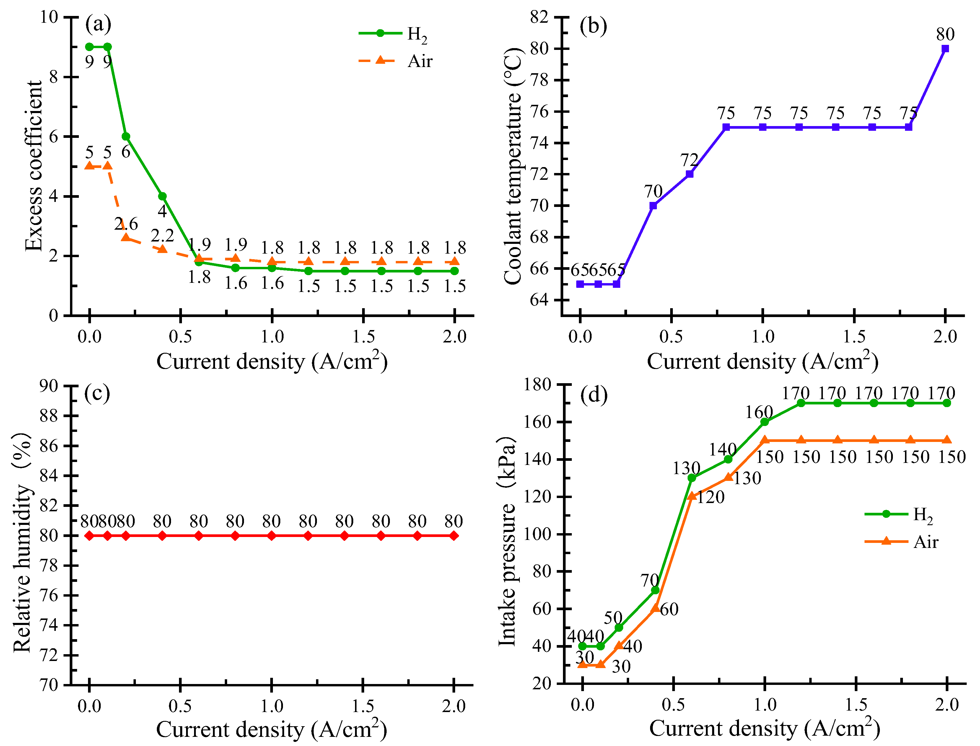
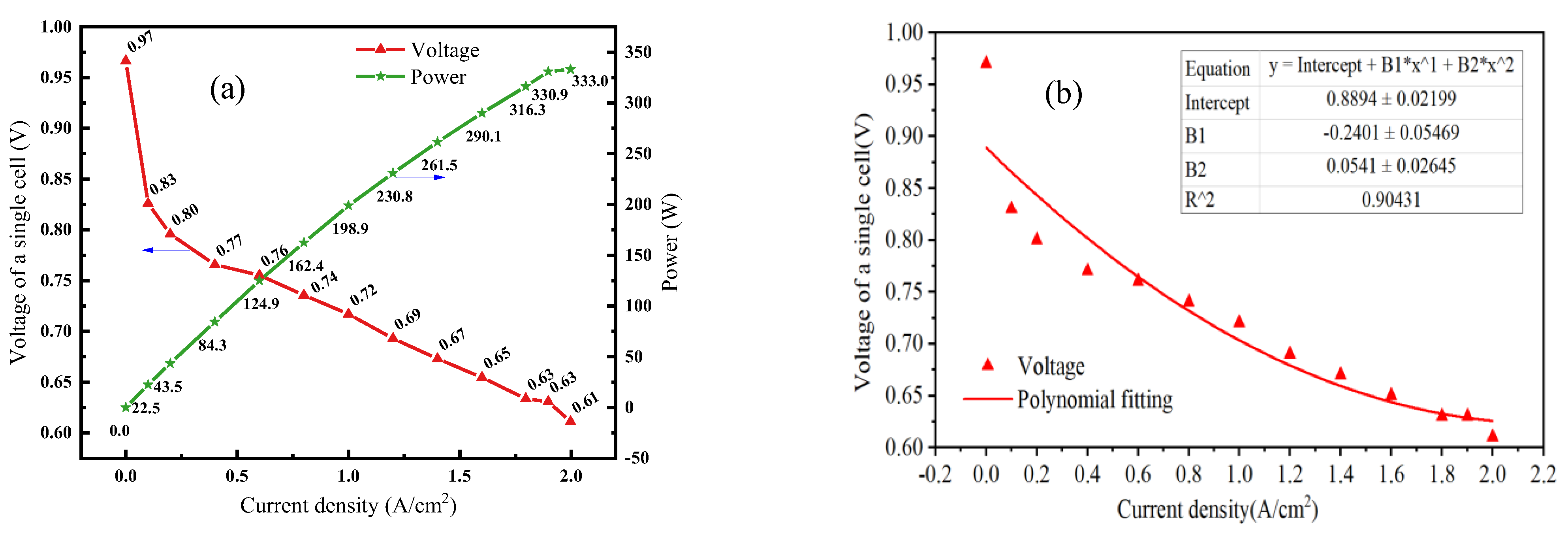
3. Results and Analysis

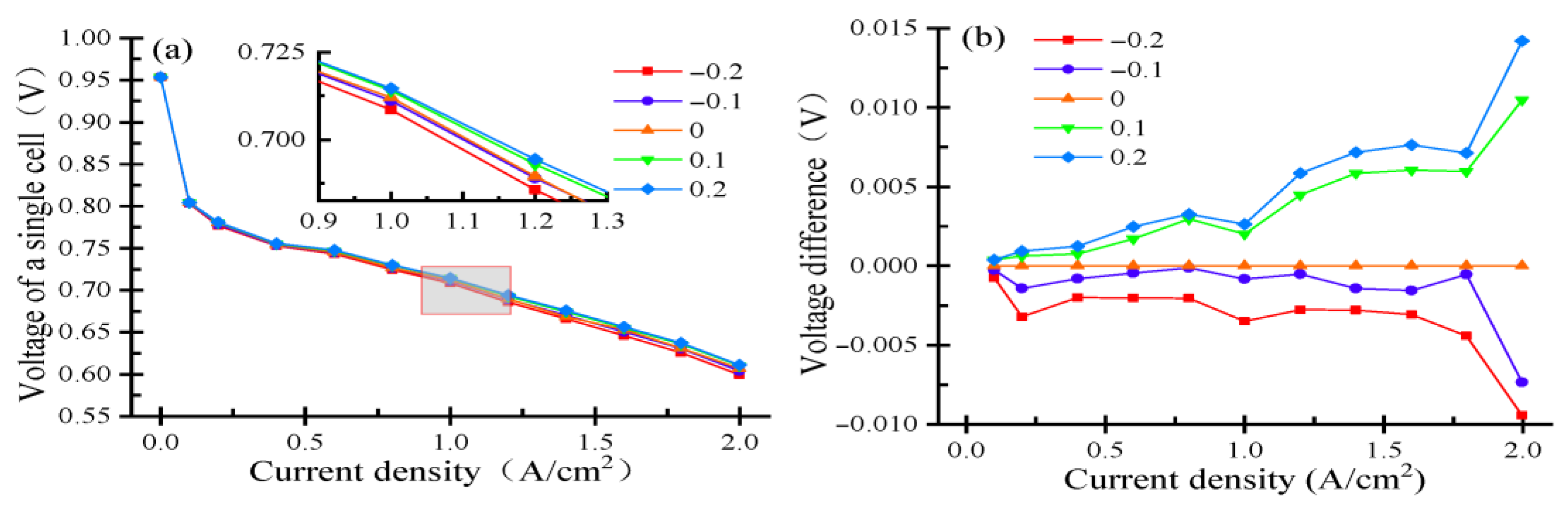
3.1. Excess Coefficient Sensitivity Analysis

The excess coefficient in FC systems represents the ratio between the actual reactant supply (hydrogen/oxygen) and the stoichiometrically required amount for the electrochemical reactions [42]. This parameter significantly influences the reaction kinetics, where an optimal value enhances current-density-efficiency characteristics while improving system dynamics [43]. The observed trend that increasing the hydrogen excess ratio (λ_H2) initially improves cell voltage but eventually leads to diminishing returns can be attributed to competing physicochemical mechanisms. At moderate λ_H2 levels, enhanced hydrogen mass transport reduces concentration polarization and promotes uniform current distribution, thereby boosting performance. However, excessive λ_H2 introduces trade-offs: (1) elevated gas flow may impede anode water removal, causing local flooding and mass transport losses; (2) reactant dilution at the catalyst layer can weaken proton activity; and (3) higher parasitic loads from auxiliary systems (e.g., recirculation pumps) indirectly reduce efficiency. The inflection point in Figure 2a reflects an optimal λ_H2 balancing these factors, consistent with PEMFC stoichiometry studies. Note that the influence of λ_air on the output voltage indeed involves a trade-off between mass transport benefits and potential limitations at high values. While increased λ_air enhances oxygen supply and reduces cathode concentration polarization, excessively high λ_air can lead to (1) significant pressure drops across the flow field due to higher gas velocities, increasing parasitic power consumption for air compression; (2) uneven gas distribution and local oxygen starvation in diffusion layers, particularly under high-current-density operation; and (3) accelerated membrane drying if flow rates exceed the humidification capacity. These effects collectively explain the plateau/decline in voltage at high λ_air values. Properly tuned excess coefficients enable both voltage stabilization and rapid power output adjustment during load variations, contributing to overall system responsiveness [44].
Figure 4 illustrates the impact of the hydrogen and air excess coefficients on FC node voltage. The study examines incremental adjustments of 0.1 and 0.2 above the baseline coefficients, along with equivalent reductions of 0.1 and 0.2 from standard operating conditions. Figure 4a presents the comparative cell voltage across various current densities and excess coefficients, while Figure 4b displays the corresponding voltage differences calculated by subtracting values from the baseline operating condition. Due to the infinite excess coefficient at zero current density, voltage measurements under excess coefficient variations were not conducted for this condition. Figure 4a demonstrates a clear positive correlation between excess coefficient values and FC node voltage. Furthermore, the magnitude of this voltage enhancement shows progressive amplification with rising current density. The data reveals a current-density-dependent relationship between the excess coefficient and voltage enhancement. At 0.1 A/cm2 current density, each 0.1 increment in the excess coefficient yields an approximate 0.3 mV voltage increase, whereas at 2.0 A/cm2, the same coefficient change produces a more substantial 10 mV gain. These results demonstrate two key trends: first, elevating the excess coefficient consistently improves node voltage, and second, this enhancement effect becomes progressively more pronounced with increasing current density. However, excessively high excess coefficients do not necessarily yield additional benefits. This is mainly determined by the relationship between the excess coefficient in the fuel cell Butler–Volmer equation and its performance [45]. In practical FC systems, hydrogen is typically supplied from high-pressure tanks through pressure-reducing valves, while air delivery relies on compressors. Increasing the excess ratio inevitably elevates compressor power consumption, which constitutes the primary energy demand in the auxiliary system [46]. Based on the relationship graph of the current and excess air coefficient shown in Figure 2a, it can be observed that for the tested FC in this study, when the excess air coefficient exceeds 2.6, it will no longer improve the voltage output. The literature [47] confirms this operational limit, demonstrating that single-cell voltage plateaus when the excess coefficient exceeds 2.5, with no further performance improvement observed despite increased energy expenditure.

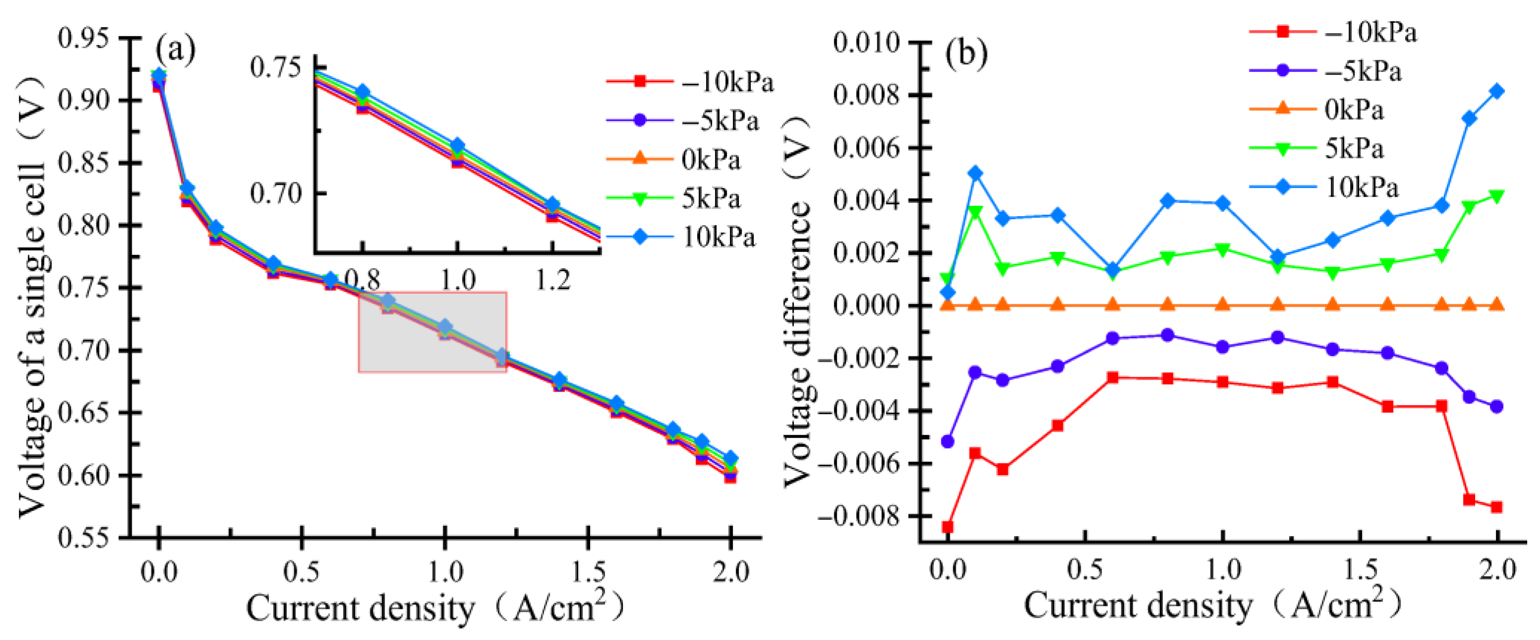
3.2. Intake Pressure Sensitivity Analysis

Intake pressure serves as a critical operational parameter in FC systems, significantly influencing performance metrics, energy conversion efficiency, and system reliability [48,49]. As shown in Figure 2d, our experimental data demonstrate good performance at moderate pressure ranges (150–170 kPa for air), which aligns well with current industrial practices where most commercial PEMFC systems operate within 150–200 kPa absolute pressure. This range represents a careful balance between performance enhancement and system limitations. At first, higher pressures would require more robust and expensive balance-of-plant components, particularly air compressors that already account for 10–15% of system parasitic losses. In addition, the mechanical integrity of stack components (bipolar plates, membranes, and seals) becomes challenging beyond 250 kPa. Furthermore, safety regulations in automotive applications typically limit operating pressures to <250 kPa absolute. Specific examples from commercial systems include the Toyota Mirai (operating at ~150 kPa) and Ballard HD modules (~180 kPa) with reference to relevant industry standards (SAE J2719 and IEC 62282-2). From a reaction kinetics perspective, elevated inlet pressure increases the reactant gas concentration in the electrochemical reaction zone, which directly enhances the hydrogen–oxygen reaction rate [50]. This pressure elevation concomitantly improves current output characteristics and overall system efficiency. Equally important, maintaining proper stack inlet pressure ensures adequate gas flow velocity, preventing detrimental water accumulation and gas stagnation during the conversion process [51,52]. System design considerations must therefore incorporate both dynamic pressure regulation capabilities and structural tolerance for pressure variations, enabling maintenance of optimal operating pressures across diverse working conditions [53].
Figure 5 demonstrates the effects of hydrogen and air intake pressure variations on FC node voltage. The experiment examines pressure adjustments of ±5 kPa and ±10 kPa relative to baseline operating conditions. Comparative voltage measurements across different current densities and pressure levels are presented in Figure 5a, while Figure 5b illustrates the corresponding node voltage differences calculated by subtracting values obtained under standard operating pressures. The experimental results reveal a positive correlation between intake pressure and node voltage across operational conditions. Analysis shows that a 5 kPa pressure increase typically yields an approximate 2 mV node voltage enhancement at most current densities. Notably, this pressure sensitivity intensifies under high-current-density conditions (2 A/cm2), where the same 5 kPa increment produces a more substantial 4 mV node voltage improvement. The observed phenomenon can be attributed to the fundamental relationship between intake pressure and key electrochemical processes in FCs. Elevated intake pressure directly impacts both the limiting current density and concentration polarization characteristics. Specifically, increasing the intake pressure enhances reactant transport to the catalytic layer by improving gas diffusion rates and expanding the effective reaction area at the three-phase boundary. This pressure-dependent effect promotes more efficient reactant–catalyst interactions, thereby accelerating electrochemical reaction kinetics and ultimately improving overall FC performance [54,55]. However, as intake pressure continues to rise beyond certain thresholds, diminishing returns become evident due to delayed concentration polarization responses. This phenomenon manifests as progressively smaller performance improvements, ultimately establishing an operational plateau. Consequently, maximum FC performance is achieved not through unlimited pressure increases, but rather by identifying and maintaining an optimal pressure range that balances reaction kinetics with system limitations by maximizing specific power or efficiency through an optimization method, such as the non-dominated sorting genetic algorithm II, the pareto archived evolution strategy, etc. Due to the limitations of the experimental conditions, there is still a lack of research on the influential characteristics of operating parameters for the important components of fuel cells, such as membrane strength limits or the risks of degradation during long-term operation under elevated pressure. In future research, we will strengthen the study and exploration in this area.

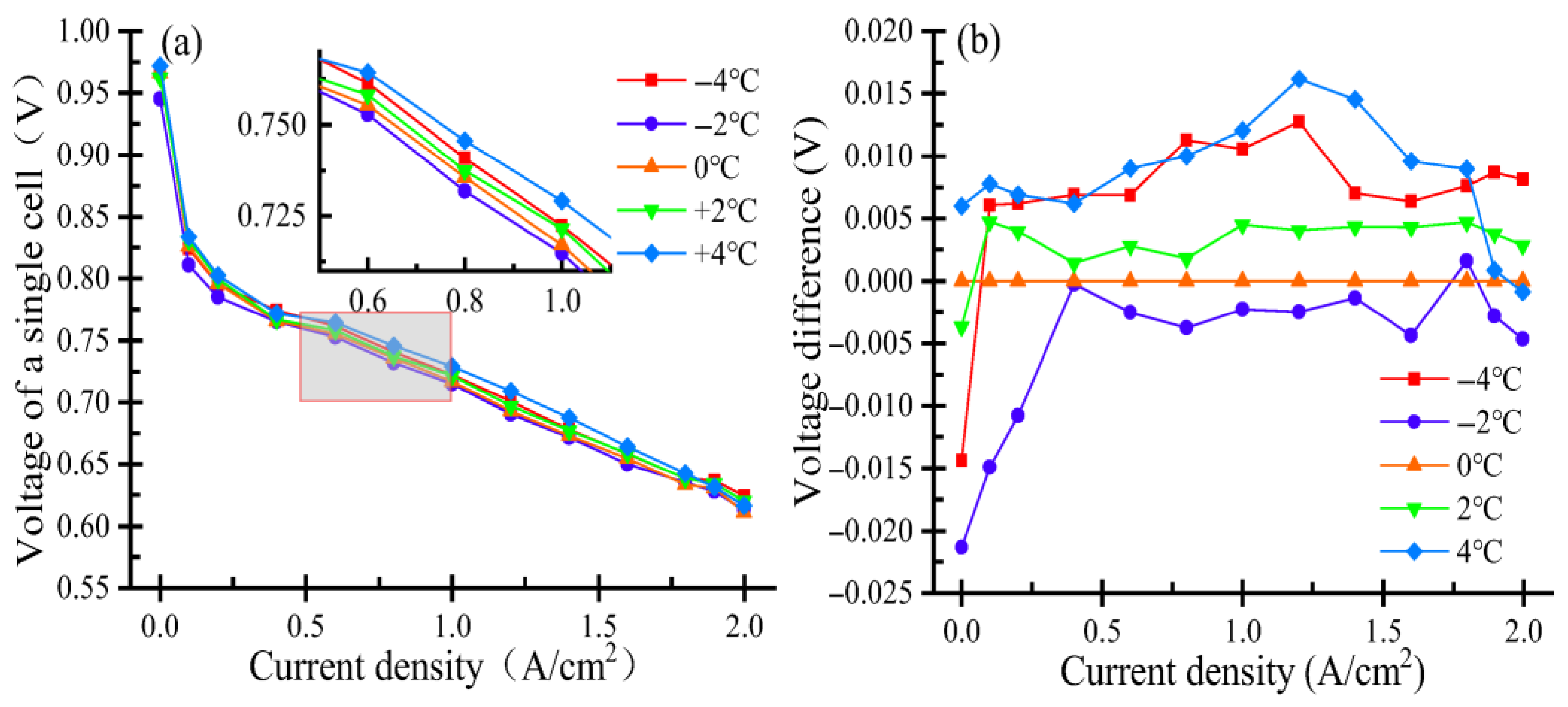
3.3. Coolant Temperature Sensitivity Analysis

PEMFCs operate as electrochemical conversion devices that transform hydrogen and oxygen into electrical energy while producing water and thermal energy as byproducts [56]. The generated heat originates from multiple sources: irreversible reaction heat from electrochemical processes, latent heat from water phase changes, ohmic heating due to ionic resistance, and thermodynamic entropy changes [57,58]. This thermal output elevates the system’s operating temperature, which critically influences the proton exchange membrane’s functional characteristics [59]. Temperature variations directly modulate the membrane’s proton conductivity while simultaneously affecting the water retention capacity in both the membrane and electrode layers. These hydration levels subsequently determine the cell’s overall impedance characteristics and power output capabilities [60]. Elevated operating temperatures in PEMFCs induce membrane dehydration, leading to reduced proton conductivity and consequent performance degradation, while extreme cases may cause irreversible membrane damage [61]. Conversely, insufficient operating temperatures prevent optimal catalyst activation, similarly compromising cell performance [62,63]. Experimental determination of precise FC temperatures presents technical challenges, although the coolant inlet temperature serves as a reliable proxy for thermal monitoring. The coolant system’s primary role involves maintaining the stack within its optimal temperature range, thereby ensuring both operational efficiency and system stability.
Figure 6 demonstrates the impact of coolant inlet temperature variations on FC node voltage performance. The experimental study examines temperature difference adjustments of ±2 °C and ±4 °C relative to baseline operating conditions. Comparative node voltage measurements across different current densities and temperature levels are presented in Figure 6a, while Figure 6b displays the derived node voltage differences calculated by subtracting values obtained under reference temperature conditions. The experimental results reveal a temperature-dependent voltage relationship across operating conditions. At moderate current densities, node voltage demonstrates a positive correlation with coolant inlet temperature. However, this trend reverses under high-current-density operation, where reduced coolant temperatures yield higher voltage outputs. Most notably, the voltage difference shows particularly strong temperature sensitivity at low current densities, as evidenced in Figure 6b. These findings suggest that optimal FC performance does not require excessively high operating temperatures. The coolant temperature exhibits strong coupling effects with other operational parameters, collectively influencing system performance [64]. Consequently, indiscriminate temperature elevation alone proves insufficient for performance enhancement, as the thermal effects are interdependent with multiple operating conditions.

3.4. Intake Relative Humidity Sensitivity Analysis

Water management represents a critical factor governing FC performance, as it directly impacts membrane conductivity and system stability. While proper hydration enhances proton transport efficiency, excessive water accumulation leads to gas diffusion channel flooding, thereby impeding reactant transport [65,66]. Consequently, precise control of inlet humidity constitutes an essential operational parameter for maintaining optimal FC performance and preventing water-related degradation mechanisms [67,68]. Figure 7 demonstrates the effects of intake relative humidity variations on FC node voltage, examining adjustments of ±10% and ±20% relative to the baseline 80% humidity condition (as established in Figure 2c). The experimental results compare single-cell voltage performance across different current densities and humidity levels in Figure 7a, while Figure 7b presents the derived node voltage differences calculated relative to the reference operating humidity. The experimental results demonstrate optimal voltage performance at most current densities when maintaining the baseline 80% relative humidity, indicating effective initial humidity control in the FC system. This is similar to the relationship proposed by S. Srinivasan et al. [69] regarding the performance of proton exchange membrane fuel cells and relative humidity. Notably, 60% relative humidity also yields generally high node voltage outputs, with peak performance observed specifically at 0.2 A/cm2 and 0.6 A/cm2 current densities. Conversely, saturated 100% humidity conditions produce the lowest node voltage outputs across all tested ranges, with the most significant performance deviation (approximately 30 mV) occurring at 1.4 A/cm2 when comparing 100% and 80% humidity conditions, as detailed in Figure 7b. This phenomenon can be attributed to the exponential dependence of saturated vapor pressure on temperature. Under high-temperature, low-humidity conditions, FCs are particularly susceptible to membrane dehydration, which significantly compromises proton conductivity [70]. Conversely, low-temperature, high-humidity operation frequently leads to cathode flooding, severely impeding reactant gas diffusion [71]. These observations align with the characteristic curve shown in Figure 6b, demonstrating the strong coupled relationship between FC operating temperature and intake relative humidity in determining overall system performance.

4. Conclusions

In this study, the sensitivity of operating parameters such as the hydrogen and air excess coefficient, inlet pressure, intake relative humidity, and coolant temperature and their effects on the performance of single PEMFCs are experimentally assessed. Specific conclusions are as follows.
(1) The FC node voltage exhibits a positive correlation with the excess coefficient, with this effect becoming more pronounced at elevated current densities. At 0.1 A/cm2 current density, each 0.1 increment in the excess coefficient yields an approximate 0.3 mV voltage increase, whereas at 2.0 A/cm2, the same coefficient change produces a more substantial 10 mV gain. However, excessively high excess coefficients prove detrimental, as they disproportionately increase compressor power consumption—the primary energy expenditure in the FC auxiliary system.
(2) The FC node voltage demonstrates a pressure-dependent enhancement, showing a characteristic 2 mV gain per 5 kPa pressure increase across typical operating ranges. Notably, this sensitivity doubles to 4 mV/5 kPa under high-current-density conditions (2 A/cm2). System optimization requires identification of an optimal intake pressure that balances performance gains with operational constraints.
(3) The FC voltage rises with coolant temperature at moderate currents but shows an inverse relationship at high current densities above 2 A/cm2, while exhibiting greatest thermal sensitivity at low currents. System optimization requires carefully balanced temperature regulation rather than maximum heating since excessive temperatures can degrade performance rather than improve it.
(4) The best results were obtained for 80% intake relative humidity. The FC performance depends critically on the coupled relationship between operating temperature and intake humidity, requiring precise coordination of these parameters for optimal system efficiency.
Through a comprehensive experimental study on the sensitivity of operating parameters of PEMFCs, this study elucidated the influence patterns of each operating parameter on the performance of the fuel cells, and has thus pointed out the direction for future research on parameter optimization to enhance the performance of fuel cells and related studies. While providing valuable insights into single-variable effects, the research identifies key gaps in understanding multi-parameter interactions and operational optimization. We acknowledge that our initial analysis did not sufficiently address the complex feedback mechanisms between operating parameters. We merely conducted a simple analysis of how a certain parameter change affects other parameters based on previous research and some theories. In future research, we will further delve into the influence of feedback between parameters by establishing an accurate simulation analysis model. We will incorporate a mechanistic or design of experiments (DOE) approach to more rigorously quantify and validate parameter interactions. First of all, we will establish an accurate performance simulation analysis model for this fuel cell stack using GT suite 2022 software. In this simulation model, a DOE approach will be utilized to analyze the influence laws of the interaction between two parameters for hydrogen pressure, air pressure, air relative humidity, and coolant temperature on the output voltage of the fuel cell stack. After that, based on the DOE research results, the relative sensitivity diagrams for each parameter’s effects on the output voltage can be obtained. At last, we will also optimize the parameters related to the performance of fuel cells.

Author Contributions

Conceptualization, L.S.; methodology, Z.Y.; software, S.W.; validation, R.F.; formal analysis, J.G.; investigation, Z.H.; resources, L.S.; data curation, X.S.; writing—original draft preparation, Z.H.; writing—review and editing, R.F.; visualization, J.Y.; supervision, L.S.; project administration, R.F.; funding acquisition, R.F. All authors have read and agreed to the published version of the manuscript.

Funding

This research was funded by the Natural Science Foundation of Chongqing, China (grant Nos. CSTB2023NSCQ-LZX0065 and CSTB2024NSCQ-MSX0389), the National Natural Science Foundation of China (grant No. 52407237), the Science and Technology Research Program of Chongqing Municipal Education Commission (grant Nos. KJQN202201150 and KJQN202401129), the Graduate Student Innovation Program of Chongqing University of Technology (grant No. gzljd2024202) and the Graduate Student Innovation Program of Chongqing (grant No. CYS25714).

Data Availability Statement

The data presented in this study will be available upon request to the corresponding author.

Conflicts of Interest

Author Laihua Shi was employed by the China Merchants Testing Vehicle Technology Research Institute Co., Ltd. The remaining authors declare that the research was conducted in the absence of any commercial or financial relationships that could be construed as a potential conflict of interest.

References

  1. Jia, D.; Qiao, J.; Liu, J.; Fu, J.; Wang, R.; Li, Y.; Duan, X. Experiment and simulation analysis of the effects of different asynchronous variable intake valve phase differences on the in-cylinder flow, combustion and performance characteristics of high compression ratio turbocharged enhanced Miller cycle engine. Energy 2025, 320, 134988. [Google Scholar] [CrossRef]
  2. Wan, S.; Zhou, F.; Fu, J.; Yu, J.; Liu, J.; Abdellatief, T.M.; Duan, X. Effects of hydrogen addition and exhaust gas recirculation on thermodynamics and emissions of ultra-high compression ratio spark ignition engine fueled with liquid methane. Energy 2024, 306, 132451. [Google Scholar] [CrossRef]
  3. Xu, L.; Liu, J.; Duan, X.; Liu, H.; Abdellatief, T.M. Effects of rebreathing exhaust gas strategy on performance behaviors of the hydrogen enriched natural gas spark ignition. Int. J. Hydrogen Energy 2025, 145, 359–370. [Google Scholar] [CrossRef]
  4. Zhang, Y.; Zhang, F.; Song, X.; Chen, R.; Chen, Z.; Duan, X.; Xia, Y. Optimization of multiple alkaline water electrolyzers coupled with solar photovoltaic power for green hydrogen production on a large scale. Int. J. Hydrogen Energy 2025, 136, 511–532. [Google Scholar] [CrossRef]
  5. Feng, R.; Hua, Z.; Yu, J.; Zhao, Z.; Dan, Y.; Zhai, H.; Shu, X. A comparative investigation on the energy flow of pure battery electric vehicle under different driving conditions. Appl. Therm. Eng. 2025, 269, 126035. [Google Scholar] [CrossRef]
  6. Guo, R.; Chen, D.; Li, Y.; Wu, W.; Hu, S.; Xu, X. Anode nitrogen concentration estimation based on voltage variation characteristics for proton exchange membrane fuel cell stacks. Energies 2023, 16, 2111. [Google Scholar] [CrossRef]
  7. Feng, R.; Yu, J.; Zhao, Z.; Hua, Z.; He, J.; Shu, X. Performance and energy consumption evaluation of fuel cell hybrid heavy-duty truck based on energy flow and thermal management characteristics experiment under different driving conditions. Energy Convers. Management. 2024, 321, 119084. [Google Scholar] [CrossRef]
  8. Ji, X.F.; Wang, X.B.; Li, Y.; Guo, J.Q.; Yang, Z.; Hao, D. Sensitivity analysis of operating parameters on a 65 kW proton exchange membrane fuel cell stack performances. Energy Rep. 2022, 8, 521–527. [Google Scholar] [CrossRef]
  9. Liu, Y.; Tu, Z.K.; Chan, S.H. Water management and performance enhancement in a proton exchange membrane fuel cell system using optimized gas recirculation devices. Energy 2023, 279, 128029. [Google Scholar] [CrossRef]
  10. Rasheed, R.K.A.; Liao, Q.; Zhang, C.Z.; Chan, S.H. A review on modelling of high temperature proton exchange membrane fuel cells (HT-PEMFCs). Int. J. Hydrogen Energy 2017, 42, 3142–3165. [Google Scholar] [CrossRef]
  11. Jiao, J.R.; Chen, F.X. Humidity estimation of vehicle proton exchange membrane fuel cell under variable operating temperature based on adaptive sliding mode observation. Appl. Energy 2022, 313, 118779. [Google Scholar] [CrossRef]
  12. Huang, Z.P.; Jian, Q.F. Cooling efficiency optimization on air-cooling PEMFC stack with thin vapor chambers. Appl. Therm. Eng. 2022, 217, 119238. [Google Scholar] [CrossRef]
  13. Rahimi-Esbo, M.; Rahgoshay, S.M.; Hassani, M.M.; Firouzjaei, K.D. Novel design and numerical evaluating of a cooling flow field in PEMFC with metallic bipolar plates. Int. J. Hydrogen Energy 2020. [Google Scholar] [CrossRef]
  14. Fikry, M.; Khavlyuk, P.; Herranz, J.; Eychmüller, A.; Schmidt, T.J. Effect of Low and Sub-Freezing Temperature on the PEFC Performance of Unsupported Pt-Ni Aerogel Cathode Catalyst Layers. In Proceedings of the 2022 ECS-The Electrochemical Society, San Francisco, CA, USA, 22–26 May 2022; Volume 1, p. 1461. [Google Scholar] [CrossRef]
  15. Xia, L.; Ni, M.; Xu, Q.; Xu, H.; Zheng, K. Optimization of catalyst layer thickness for achieving high performance and low cost of high temperature proton exchange membrane fuel cell. Appl. Energy 2021, 294, 117012. [Google Scholar] [CrossRef]
  16. Jiang, Y.; Yang, Z.R.; Jiao, K.; Du, Q. Sensitivity analysis of uncertain parameters based on an improved proton exchange membrane fuel cell analytical model. Energy Convers. Manag. 2018, 164, 639–654. [Google Scholar] [CrossRef]
  17. Jin, L.; Wang, X.J.; Zhu, J.W.; Wang, C.F.; Zhou, T.T.; Zhang, X.W. Sensitivity analysis of proton exchange membrane fuel cell performance to operating parameters and its applicability assessment under different conditions. Energy Convers. Manag. 2021, 228, 13727. [Google Scholar] [CrossRef]
  18. Carcadea, E.; Varlam, M.; Ismail, M.; Ingham, D.B.; Marinoiu, A.; Raceanu, M.; Jianu, C.; Patularu, L.; Ion-Ebrasu, D. PEM fuel cell performance improvement through numerical optimization of the parameters of the porous layers. Int. J. Hydrogen Energy 2020, 45, 7968–7980. [Google Scholar] [CrossRef]
  19. Yu, Z.; Liu, F.; Li, C. Numerical study on effects of hydrogen ejector on PEMFC performances. Energy 2023, 285, 129481. [Google Scholar] [CrossRef]
  20. Liao, X.R.; Photong, C.; Su, J.B. Sensitivity analysis and optimization of operating conditions of proton exchange membrane fuel cell. J. Appl. Electrochem. 2024, 54, 2505–2518. [Google Scholar] [CrossRef]
  21. Sezgin, B.; Caglayan, D.G.; Devrim, Y.; Steenberg, T.; Eroglu, I. Modeling and sensitivity analysis of high temperature PEM fuel cells by using Comsol Multiphysics. Int. J. Hydrogen Energy 2016, 41, 10001–10009. [Google Scholar] [CrossRef]
  22. Soomro, I.; Memon, F.; Mughal, W.; Khan, M.A.; Ali, W.; Liu, Y.; Choi, K.H.; Thebo, K.H. Influence of Operating and Electrochemical Parameters on PEMFC Performance: A Simulation Study. Membranes 2023, 13, 259. [Google Scholar] [CrossRef] [PubMed]
  23. Zhu, X.N.; Su, L.; Wang, X.; Chen, R.; Ji, S.; Ma, Y.; Lin, W.; Jian, Z.; Wei, Z. Effects of operating conditions on the performance uniformity of the proton-exchange membrane fuel cell stack. Energy Convers. Manag. 2023, 281, 116856. [Google Scholar] [CrossRef]
  24. Kang, S.; Min, K.; Mueller, F.; Brouwer, J. Configuration effects of air, fuel, and coolant inlets on the performance of a proton exchange membrane fuel cell for automotive applications. Int. J. Hydrogen Energy 2009, 34, 6749–6764. [Google Scholar] [CrossRef]
  25. Ko, D.G.; Doh, S.; Park, H.S.; Kim, M.H. Investigation of the effect of operating pressure on the performance of proton exchange membrane fuel cell: In the aspect of water distribution. Renew. Energy 2018, 115, 896–907. [Google Scholar] [CrossRef]
  26. Wang, J.; Wang, B.; Tongsh, C.; Miao, T.; Cheng, P.; Wang, Z.; Du, Q.; Jiao, K. Combining proton and anion exchange membrane fuel cells for enhancing the overall performance and self-humidification. Chem. Eng. J. 2022, 428, 131969. [Google Scholar] [CrossRef]
  27. Yuan, W.; Tang, Y.; Pan, M.; Li, Z.; Tang, B. Model prediction of effects of operating parameters on proton exchange membrane fuel cell performance. Renew. Energy 2010, 35, 656–666. [Google Scholar] [CrossRef]
  28. Kahveci, E.E.; Taymaz, I. Assessment of single-serpentine PEM fuel cell model developed by computational fluid dynamics. Fuel 2018, 217, 51–58. [Google Scholar] [CrossRef]
  29. Huang, Z.Y.; Shen, J.; Chan, S.H.; Tu, Z.K. Transient response of performance in a proton exchange membrane fuel cell under dynamic loading. Energy Convers. Manag. 2020, 226, 113492. [Google Scholar] [CrossRef]
  30. Xie, N.; Wei, W.; Ba, J.; Yang, T. Operation parameters study on the performance of PEMFC based orthogonal test method. Case Stud. Therm. Eng. 2024, 61, 105035. [Google Scholar] [CrossRef]
  31. Atak, N.; Dogan, B.; Yesilyurt, M. Investigation of the performance parameters for a PEMFC by thermodynamic analyses: Effects of operating temperature and pressure. Energy 2023, 282, 128907. [Google Scholar] [CrossRef]
  32. Hao, H.M.; Mo, R.J.; Kang, S.Y.; Wu, Z.F. Effects of temperature, inlet gas pressure and humidity on PEM water contents and current density distribution. Results Eng. 2023, 20, 101411. [Google Scholar] [CrossRef]
  33. Xu, J.-H.; Yan, H.-Z.; Ding, Q.; Zhu, K.-Q.; Yang, Y.-R.; Wang, Y.-L.; Huang, T.-M.; Chen, X.; Wan, Z.-M.; Wang, X.-D. Sparrow search algorithm applied to temperature control in PEM fuel cell systems. Int. J. Hydrogen Energy 2022, 47, 39973–39986. [Google Scholar] [CrossRef]
  34. Gao, J.W.; Li, M.; Hu, Y.F.; Chen, H.; Ma, Y. Challenges and developments of automotive fuel cell hybrid power system and control. Sci. China Inf. Sci. 2019, 62, 51201. [Google Scholar] [CrossRef]
  35. Liu, X.; Chen, J.; Jin, L.; Liu, S.B. Sensitivity analysis of current distribution to critical operating parameters for polymer electrolyte membrane fuel cells. J. Power Sources 2023, 573, 233068. [Google Scholar] [CrossRef]
  36. Zhang, B.; Chen, F.X.; Jiao, J.R.; Pei, F.L.; Zhang, W.D. Fuel cell parameter analysis and constraint optimization based on Nelder-Mead simplex algorithm considering performance degradation. Int. J. Hydrogen Energy 2024, 69, 1548–1564. [Google Scholar] [CrossRef]
  37. Albarbar, A.; Alrweq, M. Proton Exchange Membrane Fuel Cells: Design, Modelling and Performance Assessment Techniques; Springer: Berlin/Heidelberg, Germany, 2018. [Google Scholar] [CrossRef]
  38. Li, Y.K.; Zhao, X.Q.; Tao, S.Y.; Li, Q.; Chen, W.R. Experimental study on anode and cathode pressure difference control and effects in a proton exchange membrane fuel cell system. Energy Technol. 2015, 3, 946–954. [Google Scholar] [CrossRef]
  39. GB/T 28817-2022; Single Cell Test Methods for Polymer Electrolyte Fuel Cell (PEFC). China Standardization Administration: Beijing, China, 2022.
  40. Yuan, W.W.; Ou, K.; Kim, Y.B. Thermal management for an air coolant system of a proton exchange membrane fuel cell using heat distribution optimization. Appl. Therm. Eng. 2020, 167, 114715. [Google Scholar] [CrossRef]
  41. Nöst, M.; Doppler, C.; Klell, M.; Trattner, A. Thermal Management of PEM Fuel Cells in Electric Vehicles. In Springer Briefs in Applied Sciences and Technology; Springer: Berlin/Heidelberg, Germany, 2018. [Google Scholar] [CrossRef]
  42. Yin, P.; Chen, J.; He, H. Control of oxygen excess ratio for a PEMFC air supply system by intelligent PID methods. Sustainability 2023, 15, 8500. [Google Scholar] [CrossRef]
  43. Zhou, K.; Liu, Z.; Zhang, X.; Liu, H.; Meng, N.; Bai, H.; Huang, J.; Qi, M.; Song, X.; Yan, X. Effect of the high oxygen excess ratio design on the performance of air-cooling polymer electrolyte membrane fuel cells for unmanned aerial vehicles. J. Power Sources 2023, 571, 23308. [Google Scholar] [CrossRef]
  44. Zhang, C.L.; Li, H. Fixed-time observation and predefined performance regulation for oxygen excess ratio of vehicular fuel cells under input saturation. Int. J. Hydrogen Energy 2024, 69, 1022–1035. [Google Scholar] [CrossRef]
  45. Li, X.; Tan, H.; Ni, Z.; Wang, Y.; Li, C.; Han, K. Select sensitivity parameters for proton exchange membrane fuel cell model: An identification method from analytical Butler-Volmer equation. J. Power Sources 2024, 608, 234330. [Google Scholar] [CrossRef]
  46. Hu, D.H.; Liu, J.; Yi, F.Y.; Yang, Q.Q.; Zhou, J.M. Enhancing heat dissipation to improve efficiency of Two-Stage electric air compressor for fuel cell vehicle. Energy Convers. Manag. 2022, 251, 115007. [Google Scholar] [CrossRef]
  47. Qin, J.Y.; Mao, Z.Q.; Xu, J.M.; Xie, Z.G. A Study on the Characteristics of a Fuel Cell Engine with Different Excess Air Ratio. Automot. Eng. 2004, 15, 379–381. [Google Scholar] [CrossRef]
  48. Liao, P.Y.; Yang, D.J.; Ming, P.W.; Hu, K.F.; Su, G.Q.; Chen, S.Q.; Pan, M.; Li, Z. Investigation of water management for residential PEM fuel cells under ultra-low inlet pressure. Chem. Eng. J. 2024, 493, 152369. [Google Scholar] [CrossRef]
  49. d’Adamo, A.; Martoccia, L.; Berni, F.; Breda, S. An analytical methodology to maximize the fuel cells system efficiency using optimal cathodic pressure and flow rate. Int. J. Hydrogen Energy 2024, 87, 159–170. [Google Scholar] [CrossRef]
  50. Chen, H.C.; Liu, Z.; Ye, X.C.; Yi, L.; Xu, S.C.; Zhang, T. Air flow and pressure optimization for air supply in proton exchange membrane fuel cell system. Energy 2022, 238, 121949. [Google Scholar] [CrossRef]
  51. Baz, F.B.; Elzohary, R.M.; Osman, S.; Marzouk, S.A.; Ahmed, M. A review of water management methods in proton exchange membrane fuel cells. Energy Convers. Manag. 2024, 302, 118150. [Google Scholar] [CrossRef]
  52. Chen, H.C.; Liu, Y.H.; Deng, C.H.; Chen, J.R. Research on improving dynamic response ability of 30 kW real fuel cell system based on operating parameter optimization. Int. J. Hydrogen Energy 2023, 48, 1075–1089. [Google Scholar] [CrossRef]
  53. Chen, B.; Cai, Y.H.; Yu, Y.; Wang, J.; Tu, Z.K.; Chan, S.H. Gas purging effect on the degradation characteristic of a proton exchange membrane fuel cell with dead-ended mode operation, I.I. Under different operation pressures. Energy 2017, 131, 50–57. [Google Scholar] [CrossRef]
  54. Ahmadi, N.; Dadvand, A.; Rezazadeh, S.; Mirzaee, I. Analysis of the operating pressure and GDL geometrical configuration effect on PEM fuel cell performance. J. Braz. Soc. Mech. Sci. Eng. 2016, 38, 2311–2325. [Google Scholar] [CrossRef]
  55. Xia, Y.Z.; Hu, Y.W.; Hu, G.L.; Lei, H.W.; Lu, J.Z.; Wang, Z.C.; Wang, Q. Numerical analysis on the effects of manifold design on flow uniformity in a large proton exchange membrane fuel cell stack. Int. J. Hydrogen Energy 2023, 48, 5643–5655. [Google Scholar] [CrossRef]
  56. Afshari, E.; Ziaei-Rad, M.; Dehkordi, M.M. Numerical investigation on a novel zigzag-shaped flow channel design for cooling plates of PEM fuel cells. J. Energy Inst. 2017, 90, 752–763. [Google Scholar] [CrossRef]
  57. Mohamed, H.S.B.; Mohamed, A.A.A.; Tao, Q.; Li, J.; Shi, J.P.; Wang, Y.P. Liquid cooling techniques in proton exchange membrane fuel cell stacks: A detailed survey. Alex. Eng. J. 2020, 59, 635–655. [Google Scholar] [CrossRef]
  58. Tang, X.W.; Zhang, Y.J.; Xu, S.H. Temperature sensitivity characteristics of PEM fuel cell and output performance improvement based on optimal active temperature control. Int. J. Heat Mass Transf. 2023, 206, 123966. [Google Scholar] [CrossRef]
  59. Peighambardoust, S.J.; Rowshanzamir, S.; Amjadi, M. Review of the proton exchange membranes for fuel cell applications. Int. J. Hydrogen Energy 2010, 35, 9349–9384. [Google Scholar] [CrossRef]
  60. Wang, L.; Husar, A.; Zhou, T.H.; Liu, H.T. A parametric study of PEM fuel cell performances. Int. J. Hydrogen Energy 2003, 28, 1263–1272. [Google Scholar] [CrossRef]
  61. Hirpara, V.; Patel, V.; Zhang, Y.Z.; Anderson, R.; Zhu, N.; Zhang, L.F. Investigating the effect of operating temperature on dynamic behavior of droplets for proton exchange membrane fuel cells. Int. J. Hydrogen Energy 2020, 45, 14145–14155. [Google Scholar] [CrossRef]
  62. Zhang, B.; Lin, F.; Zhang, C.Z.; Liao, R.Y.; Wang, Y.X. Design and implementation of model predictive control for an open-cathode fuel cell thermal management system. Renew. Energy 2020, 154, 1014–1024. [Google Scholar] [CrossRef]
  63. Wei, L.; Dafalla, A.M.; Jiang, F.M. Effects of reactants/coolant non-uniform inflow on the cold start performance of PEMFC stack. Int. J. Hydrogen Energy 2020, 45, 13469–13482. [Google Scholar] [CrossRef]
  64. Lee, H.; Han, C.; Park, T. Experimental investigation of charge transfer coefficient and exchange current density in standard fuel cell model for polymer electrolyte membrane fuel cells. Korean J. Chem. Eng. 2020, 37, 577–582. [Google Scholar] [CrossRef]
  65. Qiu, C.X.; Su, J.B.; Shi, L. Exploration of proton exchange membrane fuel cell performance under dynamic humidification conditions. J. Indian Chem. Soc. 2024, 101, 101236. [Google Scholar] [CrossRef]
  66. Latha, K.; Vidhya, S.; Umamaheswari, B.; Rajalakshmi, N.; Dhathathreyan, K.S. Tuning of PEM fuel cell model parameters for prediction of steady state and dynamic performance under various operating conditions. Int. J. Hydrogen Energy 2013, 38, 2370–2386. [Google Scholar] [CrossRef]
  67. Xiong, Z.; Yuan, Y.P.; Tong, L.; Li, X.; Shen, B.Y. Dynamic performance analysis of proton exchange membrane fuel cell in marine applications. Energy 2024, 310, 133218. [Google Scholar] [CrossRef]
  68. Xue, Q.; Shan, Z.H.; Wang, J. Humidity impact on polarization dynamics in polymer electrolyte membrane fuel cells through distribution of relaxation times analysis. J. Power Sources 2024, 609, 234655. [Google Scholar] [CrossRef]
  69. Yang, C.; Costamagna, P.; Srinivasan, S.; Benziger, J.; Bocarsly, A.B. Approaches and technical challenges to high temperature operation of proton exchange membrane fuel cells. J. Power Sources 2001, 103, 1–9. [Google Scholar] [CrossRef]
  70. Ou, K.; Yuan, W.W.; Choi, M.; Yang, S.; Kim, Y. Performance increase for an open-cathode PEM fuel cell with humidity and temperature control. Int. J. Hydrogen Energy 2017, 42, 29852–29862. [Google Scholar] [CrossRef]
  71. Schopen, O.; Narayan, S.; Beckmann, M.; Najmi, A.; Esch, T.; Shabani, B. An EIS approach to quantify the effects of inlet air relative humidity on the performance of proton exchange membrane fuel cells: A pathway to developing a novel fault diagnostic method. Int. J. Hydrogen Energy 2024, 58, 1302–1315. [Google Scholar] [CrossRef]
Figure 1. Test single cell (left) and test bench (right).
Batteries 11 00278 g001
Figure 2. Single-cell operating conditions: (a) excess coefficient, (b) coolant temperature, (c) relative humidity, (d) intake pressure.
Batteries 11 00278 g002
Figure 3. Single-cell performance: (a) polarization curve and power, (b) the fitting curve and formula for the voltage variation characteristic.
Batteries 11 00278 g003
Figure 4. The influence of the excess coefficient on the FC node voltage: (a) voltage, (b) voltage difference.
Batteries 11 00278 g004
Figure 5. The influence of pressure on the FC node voltage: (a) voltage, (b) voltage difference.
Batteries 11 00278 g005
Figure 6. The influence of temperature on the FC node voltage: (a) voltage, (b) voltage difference.
Batteries 11 00278 g006
Figure 7. Effect of humidity on FC node voltage: (a) voltage, (b) voltage difference.
Batteries 11 00278 g007
Table 1. Parameters of a single cell.
Single Cell ParameterCompositionValue
Electrochemical reactions area-279.4 cm2
AnodePt/C catalyst10 μm
ElectrolytePerfluorosulfonic acid15 μm
CathodePt alloy catalyst20 μm
Microporous layerCarbon/PTFE mixture coated38 μm
Number of cells-1
Type of cooling-Liquid cooling
Bipolar plateMetal2 mm
Table 2. Single-cell test-bench-related parameters.
Bench ParameterUnitValue
Power test rangeW50–500
Voltage test rangeV0–40
Working temperature of PEM°CRoom temperature to 90 °C
Humidity control range%RH10–100
Anode flow rangeSLPM0.12–12
Cathode flow rangeSLPM0.5–50
Temperature difference control range°C1–10
Type of cooling Deionized water
Table 3. Single-cell test operating points.
Operating Points123456789101112
Current density (A/cm2)00.10.20.40.60.811.21.41.61.82
Disclaimer/Publisher’s Note: The statements, opinions and data contained in all publications are solely those of the individual author(s) and contributor(s) and not of MDPI and/or the editor(s). MDPI and/or the editor(s) disclaim responsibility for any injury to people or property resulting from any ideas, methods, instructions or products referred to in the content.

