Abstract
Motivated by recent developments in the field of multilevel quantum batteries, we present the model of a quantum device for energy storage with anharmonic level spacing, based on a superconducting circuit in the transmon regime. It is charged via the sequential interaction with a collection of identical and independent ancillary two-level systems. By means of a numerical analysis, we show that, in case these ancillas are coherent, this kind of quantum battery can achieve remarkable performances in terms of the control of the stored energy and its extraction in regimes of parameters within reach in nowadays quantum circuits.
1. Introduction
In recent decades, the possibility to control the puzzling features of quantum mechanics and exploit them to realize devices that are able to outperform their classical counterparts has opened the way to the development of several promising quantum technologies [1,2], among which quantum batteries (QBs) have recently emerged as a hot topic [3,4]. Indeed, since the seminal paper by Alicki and Fannes [5], numerous proposals appeared with the aim of realizing miniaturized devices taking advantage of genuine non-classical features to improve energy storage, charging power and work extraction. A large part of these ideas is based on collections of two-level systems (TLSs) directly coupled among them [6,7,8,9,10,11,12,13] or via photons trapped into a resonant cavity [14,15,16,17,18,19,20,21,22,23].
Quite recently, experimental investigations of QBs realized using superconducting circuits in the transmon regime [24,25] have been reported [26,27]. This has triggered new studies devoted to exploiting the multilevel structure of quantum systems as a way to achieve a greater and more efficient energy storage [28]. Among multilevel quantum systems, the harmonic oscillator plays a leading role due to its universality. It is therefore natural that, also in the QB literature, proposals for implementable multilevel devices based on quantum harmonic oscillators, experimentally realized for example by employing quantum LC circuits [29], have been considered [30,31].
A particularly insightful way to describe the charging of these harmonic oscillator QBs is based on the so-called collisional models [32,33,34,35,36,37,38]. Originally introduced as a way to treat quantum dissipative systems [34,39], they are based on the decomposition of the dissipative environment into a collection of elementary building blocks, usually indicated as ancillas, which interact sequentially with the quantum system of interest. In general, the irreversible interaction with the environment is non-Markovian and typically leads to thermalization and energy losses from the system [32,33,34,39,40,41]. However, the same collisional models can also be used as an active way to charge a QB via the proper control of the quantum state of the ancillas and of the duration of their interaction with the QB [42,43,44,45].
Particularly interesting in this direction is the case where the QB is a resonant cavity [46,47,48,49]. This configuration is reminiscent of the micromaser experiments carried out by S. Haroche and coworkers, where quantum states of radiation were engineered and characterized via a controlled flow of Rydberg atoms [50]. For properly fine-tuned values of the parameters, this charging protocol leads to a very stable energy storage due to the emergence of trapping chambers [51]. Here, after a given number of collisions with the ancillas, the QB reaches a configuration where the energy cannot be further reduced or increased and remains stably stored. As emerges from these works, the key advantage presented by collisional charging with respect to more conventional charging protocols for QBs, is that they allow the transfer of a greater amount of energy to the battery. Indeed, each charger intervening in the charging process can contribute to the building of a highly excited state of the battery, a goal which is not often achievable through the coupling with a single charger.
In view of possible implementations in solid-state platforms, it is relevant to investigate the same collisional charging protocol in state-of-the-art quantum circuits such as the transmons [24,52]. Here, the multilevel spectrum is characterized by anharmonicity, which is the essential ingredient to properly realize effective two-level systems, playing the role of qubits for quantum computing [25,53]. In this direction, the present paper aims at characterizing the charging and energy extraction efficiency of a transmon QB charged by means of a collisional approach. Through numerical analysis, we will show that the charging realized by means of independent and coherent ancillas leads to a (slightly damped) oscillating behavior as a function of the number of collisions, whose functional dependence on the battery–ancilla coupling and coherence within the ancillas can be characterized through best fits. For short enough duration of the collisions, the energy stored in the QB remains stably within the cosine potential well induced by the Josephson energy of the transmon [54], and in correspondence with the first maxima of the oscillations, it can be almost completely extracted as useful work. Here, both the period of the oscillations and the damping depends on circuit–ancilla coupling and, quite unexpectedly, on the coherence of the ancillas and not on their energy. For longer interaction durations, despite the greater amount of stored energy, the system shows beats and instabilities, which progressively lead to a reduction in the efficiency of energy extraction. When the charging is realized by means of incoherent ancillas, the stored energy shows a completely different behavior as a function of the number of collisions: the oscillations disappear, and the value of the stored energy depends on the coupling and on the energy initially trapped in the ancillas. In addition, the efficiency of the energy extraction only approaches .
The article is organized as follows: In Section 2, we describe the model for a transmon QB. The relevant parameters characterizing the device, the details of the considered collisional charging protocol and the relevant figures of merit are also discussed. Section 3 reports the results achieved by numerically studying the transmon QB in the presence of repeated interactions with coherent and incoherent ancillas, for different values of the circuit–ancilla coupling, initial state of the ancillas (assumed identical) and the times of collision. Considerations about the actual experimental feasibility are also reported here. In Section 4, we comment on the results and draw some conclusions. For completeness, Appendix A and Appendix B are devoted to the discussion of the experimentally very challenging regime of short times of collision and the effects of the reduction in ancillary coherences, respectively.
2. Model
2.1. Quantum Battery
As a model for a multilevel QB, we consider a superconducting circuit in the transmon regime (see scheme in Figure 1). It is realized using a SQUID [55,56] shunted with a large capacitance and connected to a gate potential via a further capacitance [24].
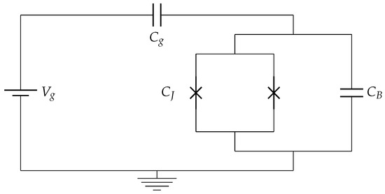
Figure 1.
A scheme of a transmon circuit. It is composed of a SQUID (realized by two Josephson junctions in parallel) with an intrinsic capacitance . is a large external capacitance connected in parallel with the SQUID, while indicates the gate capacitance and the gate voltage.
The Hamiltonian associated with this circuit can be written as (from now on, we will assume ) [24,29,54]
where is the number operator of Cooper pairs transferred between the two superconducting islands forming the SQUID, and is its conjugate variable, representing the superconducting phase difference across the SQUID. Together, they satisfy the commutation relation . The parameter , which represents the charging energy of the circuit, is given by , with e representing the electron charge and . On the other hand, is the Josephson energy associated with the tunneling of Cooper pairs [24]. The parameter is an offset controlled by changing the gate potential , and its role will be clarified later.
Since the cosine potential well in Equation (1) is finite, shows a discrete set of anharmonic bound levels within the well and a continuum of energy levels outside of it [57]. For the generic values of the parameters, the Schrödinger equation for can be solved, working in the basis of eigenstates of , in terms of Mathieu’s special functions [24]. This results in a set of anharmonic energy levels (with ) depending on [24,25].
The so-called transmon regime [24,25] is achieved when , a condition obtained in practice by using a large shunting capacitance to strongly reduce the charging energy of the circuit.
Figure 2 shows the behavior of the energy eigenvalues as a function of and for different values of . In the regime , the energy levels are strongly dependent on , so that the role of the gate voltage is to tune this parameter to the optimal working point of the circuit, which, however, is still sensitive to gate fluctuations [24,54]. Remarkably, we observe that, by approaching the transmon regime (see Figure 2a–d), the dependence on of the low-energy levels progressively disappears, making the circuit almost immune to charge fluctuations.
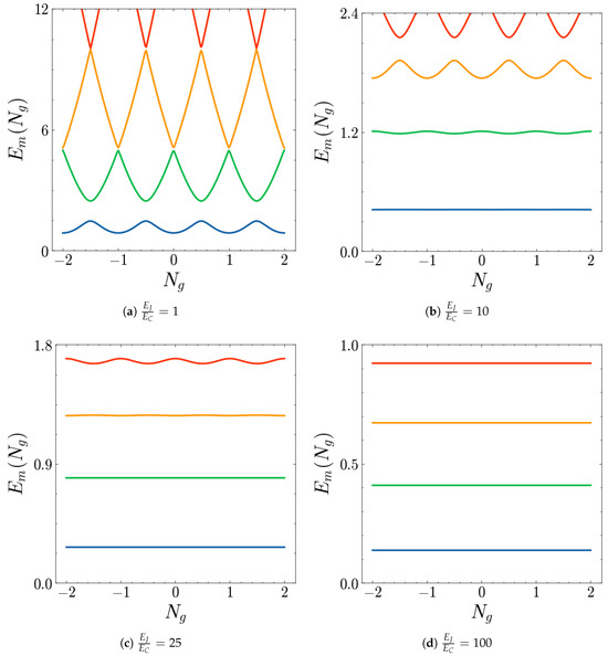
Figure 2.
Plot of the energy levels of the Hamiltonian in Equation (1) (in units of ) for (blue), 1 (green), 2 (orange), 3 (red) as functions of for different values of the ratio .
Indeed, deep in the transmon regime, can be approximated as a Duffing oscillator [57,58,59,60] by Taylor expanding the cosine potential, obtaining
The justification of this expansion is that, if , the height of the well is much greater than the kinetic part of Equation (1), so that the system remains near , the minimum of the well. The effectiveness of this expansion clearly emerges by writing and in terms of the ladder operators and of a quantum harmonic oscillator, namely
where is the Josephson plasma frequency of the transmon. These relations guarantee that the canonical commutation relation between and is satisfied if .
By writing the resulting Hamiltonian in units of the plasma frequency, one obtains
This helps identifying, as a perturbative parameter, the ratio , so that Equation (5) can be treated perturbatively to lowest order in . Such an approach leads to the following gate-independent expression for the low-energy levels in units of [24]
As shown in Figure 3, the relation derived above is a good approximation for the transmon energy levels within the well (blue curves), whereas fluctuations with respect to become relevant only outside of it.
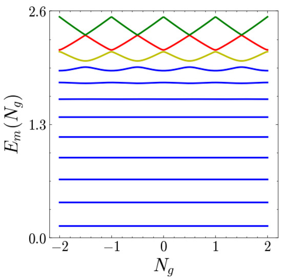
Figure 3.
Plot of the energy levels of the Hamiltonian in Equation (1) (in units of ) as functions of for . The states shown are both the trapped states (represented with blue curves) and the states outside the potential well (yellow), (red) and (green).
In the regime considered above, it is possible to estimate the relative anharmonicity of the spectrum, defined as
where . Making use of Equation (6), one obtains
which, since in the transmon limit , reduces to
which is the same result obtained for the perturbative parameter in the transmon regime. The same ratio appearing in Equation (9) determines, at least approximately, the number of bound states in the cosine well of the transmon, as given by [57]
These features are the main reasons behind our choice of the transmon superconducting circuit as the QB: by increasing , the number of bound energy levels increases, leading to a multilevel structure that is both anharmonic and charge-insensitive.
2.2. Charging Protocol
The QB is charged through the sequential interaction with a collection of TLSs, a process that fits in the framework of collisional models [34]. According to this, we will then refer to the individual collisional units both as ancillas and chargers, whereas we will indicate the single QB–charger interaction as a “collision”. From now on, we will denote by the QB density matrix after n steps of QB–charger interaction, namely, , with representing the duration of each interaction. We also define as the set of initial density matrices that describe the chargers.
The general dynamics of a system undergoing many collisions can be quite involved. In fact, interactions and correlations among the ancillas may lead to memory effects, so that the density matrix of the system after n collisions depends, in general, on all the previous steps of the sequence of interactions. Since, in a collisional charging process, ancillas are quantum systems that need to be properly engineered, this work has been carried out assuming the possibility of controlling them in such a way that they are non-interacting and initially uncorrelated (see Section 3.3 for further details). These conditions, together with the assumption of chargers that individually interact with the QB, guarantee Markovian dynamics [34], which means that the state of the system after the n-th interaction depends only on the state of the n-th charger and on the state of the QB at the end of the previous step ().
For simplicity, we also assumed a homogeneous collision model, with identical chargers (each charger prepared in the same quantum state) interacting with the QB through a formally identical coupling Hamiltonian and an identical interaction duration .
In order to properly describe the collisional dynamics, one can start with the interaction between the system and a single charger. The Hamiltonian encoding the interaction between the transmon and the n-th charger consists of three terms
where and represent the free Hamiltonian of the QB, given by Equation (1), and the free Hamiltonian of the n-th TLS charger, of the form
respectively, with representing the conventional Pauli matrix along the z direction and the level spacing of the qubit. Its eigenstates will be denoted by .
As for the coupling between the QB and the n-th charger, the following time-dependent interaction Hamiltonian is considered
where and . Thus, the coupling between the battery and the n-th charger is turned on at (the first collision is labeled with ) and switched off at , so that the duration of each interaction is always . The coupling strength g is the same for each step considered, as required by the homogeneity assumption. As we will see when discussing the experimental feasibility of our battery, such kinds of interaction Hamiltonians can be realized by capacitively coupling two superconducting circuits in the transmon regime [25], with one playing the role of the ancilla characterized by a greater anharmonicity in such a way as to be properly described as a TLS.
The entire work has been carried out neglecting thermal effects due to the cryogenic working temperatures of the superconducting circuits forming the transmon battery, which usually are of the order of mK [61].
We assume that the first collision occurs at , when the battery is prepared in its ground state and each ancilla is prepared in a given superposition of ground () and excited state (), namely,
in order to capture effects due to quantum coherences. In fact, as pointed out in [44], the presence of quantum coherences in the collisional charging of a harmonic quantum battery can lead to noteworthy advantages in storage performances. The aim of our analysis is to investigate the possibility of taking advantage of these quantum coherences also in the presence of anharmonicity. Here, the real parameter c has been introduced to distinguish between a perfectly coherent charging protocol () and an incoherent one . At fixed c, the parameter q can be used to control both the coherences of the charger and its populations.
The charging protocol then proceeds through a sequence of N collisions, the n-th of which goes as follows:
- At time , the QB is coupled with the n-th TLS charger, so that the resulting composite system undergoes a unitary evolution described by the Hamiltonian ;
- At time , the coupling is switched off;
- This procedure is iteratively repeated by coupling the QB with subsequent chargers until one obtains the desired value of a relevant figure of merit (see below).
Starting from the following initial state for the whole system (QB + N chargers)
which satisfies the requirement of initially uncorrelated ancillas, the Markovian time evolution of the QB density matrix can be obtained as [34]
where we have defined the quantum map
with denoting the unitary evolution operator for the QB+n-th charger composite system. The role of this map in the dynamics of the system is to connect the QB density matrix at two subsequent steps. As is usually conducted, for the sake of simplicity, in the context of collision models, our calculations will be performed in the interaction picture. Since an analytical expression for the quantum map is out of reach for our model, we have employed a numerical approach based on the QuTip toolbox [62] to solve the stepwise evolution of . Within each system–ancilla interaction, the time evolution of has been determined numerically solving the von Neumann equation of the system–ancilla global density matrix and subsequently tracing over the ancillary degrees of freedom.
2.3. Figures of Merit
The first figure of merit needed to characterize the performances of the QB is the energy stored as a function of time (here the number of collisions), defined as [14,63]
The extraction of such energy occurs via unitary operations acting on the battery [64,65]. Such operations lead to a maximum amount of extracted energy , leaving the battery in a passive (empty) state [66]. The maximum energy that can be extracted via unitary operations is called ergotropy and is defined as [67]
Here, represents a generic unitary discharging operation, which is applied to the QB once the energy has been stored in it, in order to extract it as useful work. Notice that, denoting with d the dimensionality of the battery Hilbert’s space, in the second term, a minimization in the space of the unitary operations acting on the d-dimensional quantum system is carried out.
Given the following spectral decompositions of the battery Hamiltonian and state
the ergotropy can be evaluated without carrying out explicitly the minimization as [67]
It is then useful to characterize the extraction process through the energy extraction efficiency of the QB, defined as [28,30,68]
This, together with the stored energy, is a key figure of merit, which allows one to identify the optimal working conditions for the transmon QB: the higher , the more available the stored energy actually is as useful work.
3. Results
In this section, we show the numerical results obtained via the QuTip toolbox [62] concerning the collisional charging of a superconducting QB in the transmon regime. We will analyze the stored energy and the efficiency as functions of the collisional step n in different regimes of the parameters.
Since, as stated above, the transmon QB bound states are insensitive to the value of , we can safely set for all the following discussions without the loss of generality. Moreover, the gap of each charger will be assumed to be in resonance with the first energetic gap of the transmon spectrum, namely, . A perfect fine-tuning of is not needed, since slight deviations from this condition did not lead to major deviations from the results we are going to show. We expect, however, that a consistent reduction in the gap could cause disruptive effects, since it would bring the ancillas far from the resonance with the bound spectrum gaps of the transmon.
Recalling Equation (14), two different situations will be considered:
- (i)
- A coherent charging protocol, where and , as discussed in Section 3.1;
- (ii)
- An incoherent charging protocol, where , as discussed in Section 3.2.
Both analyses will focus on coupling values in the regime , which fits the regime usually indicated as strong coupling, where the coupling is greater with respect to the system loss rates [69].
Concerning the interaction duration of each collision, considering, as a reference time scale, the inverse of the plasma frequency of the superconducting circuit , we focused mainly on sequences of interactions with . The regime with would require manipulations of the ancillary circuits faster than the scale , whose typical values are of the order of a few nanoseconds (see Section 3.3 for more details). Given the technical difficulty in manipulating superconducting circuits at such short time scales, the regime appears less appealing in view of experimental realizations. Additional considerations about this regime are reported in Appendix A, whereas the intermediate regimes of ancillary coherences will be discussed in Appendix B.
3.1. Coherent Charging
When , the off-diagonal entries of are non-zero, provided that ; they are maximal at and symmetric with respect to this value in the same interval. This means that, by comparing two charging protocols with q and , we are making a comparison between situations where the chargers have the same coherences and exchanged populations.
3.1.1. Collision Time
For this regime, the results are summarized in Figure 4, which show the stored energy as a function of n and q for two different values of the coupling g.
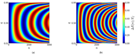
Figure 4.
Density plots of the stored energy (in units of ) as a function of the number of collisions n and of the parameter q for (a) , (b) . The other parameters are , and .
For each of these, if q is fixed, the QB oscillates between the ground state and a charged state where the energy approaches , namely, the top of the cosine potential well. This guarantees that, provided one is able to stop the charging process at the right time, the QB can be driven from its ground state to the top of the potential well.
The stored energy is symmetric with respect to the axis, so that there is no difference between the two charging protocols characterized by ancillary parameters and satisfying . This means that charging protocols with the same quantum coherences at the level of the chargers show the same evolution of the stored energy, regardless of their different populations (and energies). Thus, at least for what concerns values of g in the lowest part of the coupling interval considered, the quantum coherences of the chargers seem to be ultimately responsible for the QB dynamics.
Other interesting features emerging from Figure 4 concern the frequency of the energy oscillations. The more noticeable fact is that the frequency is higher at higher coupling. It is also symmetric with respect to , where it reaches its maximum value, decreasing as q moves toward or . These last points can be seen more easily in Figure 5a and Figure 6a, showing, for the values of the coupling introduced above, the stored energy as a function of n for three different values of q.
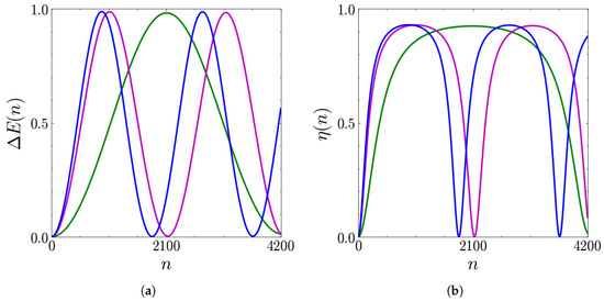
Figure 5.
Stored energy (in units of ) (a) and extraction efficiency (b) as functions of the number of collisions n for (green line), (purple line), (blue line). The other parameters are , , and .
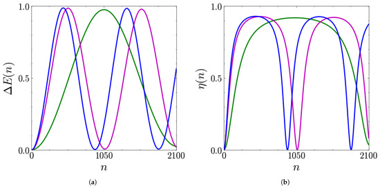
Figure 6.
Stored energy (in units of ) (a) and extraction efficiency (b) as functions of the number of collisions n for (green line), (purple line), (blue line). The other parameters are , , and .
Clearly, Figure 6a shows the same number of oscillations as Figure 5a, but within a halved period (doubled frequency). In addition, these figures show that the frequency decreases dramatically for , being maximal at .
Taking into account all these facts, and given the form of the coherent terms in the density matrix of the ancillas, a reasonable ansatz for the frequency seems to be
with being a proper scale factor. We will further investigate this assumption in Section 3.1.2.
Thus, by increasing the coupling, the frequency increases so that the charging is faster and is characterized by a higher power. This feature recalls the behavior of harmonic systems such as the Dicke QBs, where a greater QB–charger coupling leads to a faster charging [14,70,71].
Once the behavior of the stored energy has been discussed, the problem of efficient energy extraction can be addressed. To this end, the results for the energy extraction efficiency are shown in Figure 5b and Figure 6b for the two considered values of the coupling.
The oscillations performed by the efficiency reach a maximum value of in correspondence with the energy maxima. We also notice that this quantity is flatter around its maxima than . This is of great relevance since it guarantees that a significant fraction of the stored energy can be extracted as useful work even without stopping the charging at its exact maximum.
Therefore, in this regime, the battery is able to store a large amount of energy (of the order of ):
- (i)
- In a short time, , with representing the number of collisions needed to reach the first maximum, which is as little as 400–1000, corresponding to a charging duration of μs (see Section 3.3 for more details);
- (ii)
- With a very large extraction efficiency, reaching peaks with .
An aspect that still needs to be investigated is how stable the discussed properties are with respect to variations in the coupling. The results are shown for both the fastest and slowest charging cases considered before, namely, (see Figure 7) and (see Figure 8). Focusing, in particular, on the stored energy, it is clear for both (see Figure 7a) and (see Figure 8a) that increasing the coupling leads to faster oscillations (shorter period).
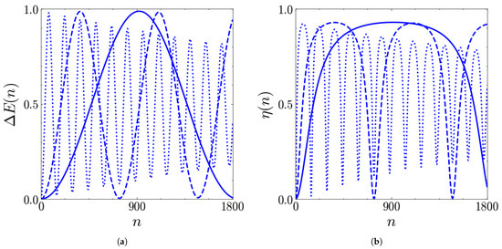
Figure 7.
Stored energy (in units of ) (a) and extraction efficiency (b) as functions of the number of collisions n for (solid), (dashed), (dotted). The other parameters are , , and .
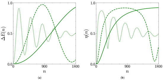
Figure 8.
Stored energy (a) and extraction efficiency (b) as functions of the number of collisions n for (solid), (dashed), (dotted). The other parameters are , , and .
Moreover, one can note the emergence of a damping effect at high couplings (dotted lines), which is stronger for (low coherences of the ancillas), if compared with (high coherences of the ancillas), suggesting that the quantum coherences protect the battery from this damping.
All considered, two scenarios arise: if one has a great control on the device, higher couplings can be useful to obtain a charged QB in short times (small number of collisions) avoiding the significant decrease of the stored energy; if, on the other hand, this fast control is not technically achievable, it could be convenient to work at weaker couplings where the effects of the damping become relevant only after a huge amount of collisions (see Figure 5a and Figure 6a). The convenience of slower oscillations (weaker couplings) at long times is supported by the efficiency of the energy extraction, as shown in Figure 7b and Figure 8b. Here, in fact, the stronger coupling exhibits the same efficiency as the weaker one only for a few collisions, being characterized by a faster decay.
3.1.2. Frequency and Damping of the Stored Energy Oscillations
The aim of this section is to characterize the behavior of the stored energy in a more detailed way. In the absence of an analytical expression for the dynamics of the transmon under collisional charging, its behavior, as a function of , can be phenomenologically estimated from the damped oscillations shown so far, leading to the expression
with denoting the frequency of its oscillations and the damping coefficient. The results for these parameters, as functions of g and q, have been obtained by fitting the stored energy curves with Equation (25) for many different values of q and g.
Starting from the frequency, we prove the ansatz in Equation (24), focusing, in particular, on the first oscillations, where we can neglect the damping. These oscillations are also the most relevant ones in view of applications where fast charging is important. The results for are shown in Figure 9.
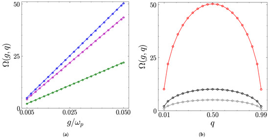
Figure 9.
(a) Frequency (in units of the scale ) as a function of for different values of q: 0.05 (green), 0.25 (purple) and 0.5 (blue). (b) (in units of the scale ) as a function of q for different values of : 0.005 (grey), 0.01 (black) and 0.05 (red). The circles represent the numerical values obtained from the stored energy curves, and the solid lines represent the fit function. The other parameters are , and .
As shown in Figure 9a, the frequency grows linearly with the coupling , regardless of the value of q, which only determines the slope. Furthermore, as first noticed in the previous section, at a given coupling, the frequency is maximal when . This can be seen in Figure 9b, where we considered the frequency as a function of q for different values of . As expected from the density plot of the stored energy, is symmetric with respect to the axis. Fitting its values with the ansatz
we find that the best values of the above parameters are , and , so that the q-dependent term in Equation (26) is the same factor appearing in the coherences of the chargers. Thus, the results shown above for the frequency provide further evidence that the quantum coherences of the chargers are directly responsible for the oscillatory behavior of the collisional charging.
Focusing now on the damping coefficient, the results are shown in Figure 10. As hinted in Section 3.1.1, the damping effects become more relevant at higher couplings. It is also symmetric with respect to , where it reaches its minimal value for all the couplings considered. This is in agreement with the previous discussion and represents a very relevant feature: maintaining maximum quantum coherences at the level of the chargers protects the stored energy oscillations from the damping. Fitting its values with the ansatz
we find that for each of the curves in Figure 10a. In terms of the other parameters, their values show a residual slight dependence on the coupling, which is summarized in Table 1 for the curves shown in Figure 10b.
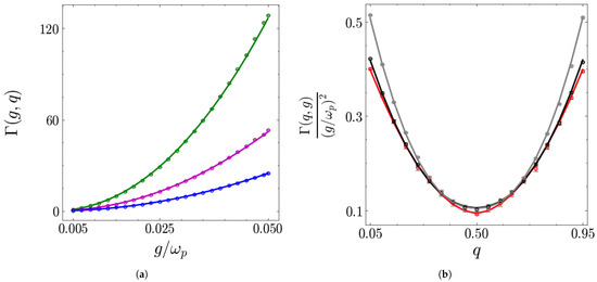
Figure 10.
(a) in units of the scale as a function of for different values of q: 0.05 (green), 0.25 (purple) and 0.5 (blue). (b) in units of the scale as a function of q for different values of : 0.005 (grey), 0.01 (black) and 0.05 (red). The circles represent the numerical values obtained from the stored energy curves, and the solid lines represent the fit function. The other parameters are , and .

Table 1.
Values of the fit parameters for for the three coupling values shown in Figure 10b.
3.1.3. Different Durations of the Interaction
After having considered the consequences of increasing the coupling, let us now turn to what happens when varying the duration of each collision. As anticipated, we will focus on increasing the duration (see Appendix A for further details). We will discuss the fastest charging case, namely, , since analogous results are found also for the other values of q.
We start by varying while keeping in the lowest part of the interval considered. The results for the energy storage and extraction are shown in Figure 11. Oscillations like the ones pointed out for are still present for the intermediate duration considered (). This is of great relevance since it shows that a perfect fine-tuning is not needed to store energy in the battery. Furthermore, we see that for this larger value of the interaction time, the oscillations are a little faster.
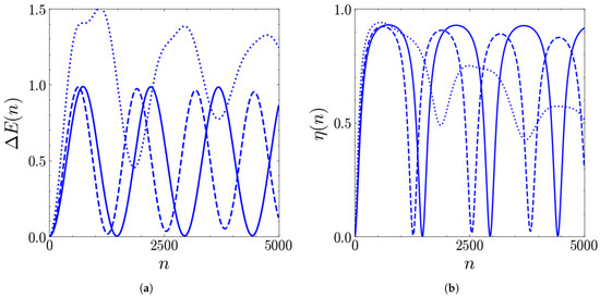
Figure 11.
Stored energy (in units of ) (a) and extraction efficiency (b) of the QB as functions of the number of collisions n for different values of (solid line), (dashed line), (dotted line). The other parameters are , , and .
However, by further increasing the duration, one observes a different behavior both at the level of the stored energy (Figure 11a) and energy extraction efficiency (Figure 11b). In fact, focusing in particular on the former, the periodic and weakly damped oscillations are lost, replaced by irregular beats that exceed the maximum amount of energy that can be stored in the well. This behavior is due to the fact that the non-bound states of the transmon QB are relevantly populated, and it becomes even more irregular when increasing the coupling. This is reported in Figure 12, which also shows that the symmetry of the stored energy with respect to is lost in this regime. This is a signature of the fact that, in this regime, the coherences of the ancillas are not the only factor responsible for the charging dynamics.
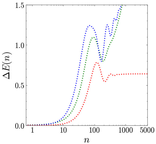
Figure 12.
Stored energy (in units of ) as a function of the number of collisions n for different values of q: (green line), (blue line) and (red line). The other parameters are , , and .
The rapidly increasing stored energy in this long-duration regime can be useful if one is interested in storing as much energy as possible. However, oscillations like the ones obtained for smaller durations guarantee long-term repeatability, which can be useful to maintain control over the system and its stability.
Within this section, we have used the parameter q to control both coherences and populations. Deviations from the maximally coherent situation at fixed q can be examined by reducing the c parameter below . This takes into account the possibility of decoherence at the level of the ancillas waiting for the interaction with the QB. Appendix B is devoted to a discussion of this case.
3.2. Incoherent Charging
In this section, we compare the coherent and incoherent charging protocols. In the incoherent case (), the chargers can only contribute via their populations, controlled by the parameter q, which goes from (ground state) to (excited state).
3.2.1. Collision Time
According to the analysis carried out in Section 3.1, it clearly emerges that the charging dynamics crucially depend on the coherences of the chargers. Therefore, by turning them off, we expect the stored energy to be negligible with respect to the coherent case. In fact, this is the case. Moreover, we needed to move toward greater values of the coupling in order to obtain an incoherent stored energy comparable to the coherent one. The numerical results reported in Figure 13 show the density plot of the stored energy as a function of both n and q for two representative values of the coupling.
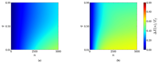
Figure 13.
Density plots of the stored energy (units of ) as a function of the number of collisions n and of the ancillary parameter q for (a) , (b) . The other parameters are , and .
First of all, we notice that the oscillating behavior of disappears. However, the greater coupling allows for the storage of a significant amount of energy, which, at long times, becomes comparable with the coherent case stored energy and which is no longer invariant under . As expected in this case, the charging performances are better near , namely, for (almost) full chargers.
The loss of the symmetry in the incoherent case can also be visualized in Figure 14a, where the coherent charging protocols with and (which lead to the same in the coherent case due to the symmetry) are compared with the respective incoherent protocols.
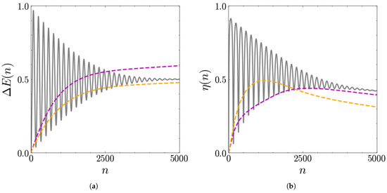
Figure 14.
Stored energy (in units of ) (a) and extraction efficiency (b) as functions of the number of collisions n. Comparison between the coherent protocol for and (solid grey line) with the corresponding incoherent ones: dashed purple for ; dashed orange for . The other parameters are , , .
Figure 14 highlights other remarkable differences:
- At short times, the energy stored in the coherent case is greater than that of the incoherent case;
- At long times, the coherent oscillations are damped until reaching a value which is comparable with the stored energy of the incoherent case and, in some cases, even lower.
Figure 14b shows the corresponding results for the extraction efficiency. In the incoherent case, it barely reaches . Thus, provided that we are able to stop the evolution at short times, the coherent charging protocol proves to be convenient also for higher values of the coupling.
Let us now turn to a more detailed study of the stored energy of the incoherent protocol. Given previous results, we assume it to be of the form
with representing the inverse of the charging time of the battery and the asymptotic value reached after the stored energy flattens. The numerical values for these parameters have been obtained by fitting the stored energy curves with Equation (28) for different values of g and q. The results for the fit procedures are shown in Figure 15.
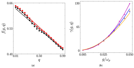
Figure 15.
(a) in units of as a function of q for different values of : (grey), (black), (red). (b) in units of the scale as a function of for different values of q: 0.5 (blue), 0.25 (purple) and 0.75 (orange). The circles represent the numerical values obtained from the stored energy curves, and the solid lines represent the fit function. The other parameters are , and .
Figure 15a shows that the asymptotic value reached by the stored energy at long times is almost insensitive to coupling variations, whereas it decreases roughly linearly. However, even if , a considerable amount of energy is stored. This suggests the assumption
By fitting the numerical values obtained for the stored energy fit, one obtains and . The origin of b, namely, the value of the energy asymptotically stored in the battery when , can be traced back to the energetic contribution needed to switch on and off each QB–charger coupling [42,68]. This splits into two parts: one is gained by the ancillas, whereas the other is transferred directly to the QB. Such switching contributions arise whenever the battery and interaction Hamiltonians do not commute with each other [63], as happens in the present case.
In contrast, Figure 15b shows a completely different behavior for , which represents the inverse of the charging time scale of the incoherent protocol: it strongly increases with , whereas it is almost insensitive to variations of q. Assuming consistently that
the optimal values for the parameter to fit the numerical data obtained is , whereas is a scale of the order of with a slight dependence on q, which, however, is negligible with respect to the dependence on g.
This is in agreement with what was anticipated at the beginning of this section: the incoherent protocol at weaker couplings is characterized by a small , which corresponds to a large charging time, so that one needs a huge number of collisions to store a significant amount of energy into the QB.
3.2.2. Different Durations of the Interactions
Furthermore, in the incoherent case, variations in the duration can affect the dependence of the stored energy on the number of collisions. This clearly emerges from Figure 16, where we compare incoherent charging protocols with different values of .
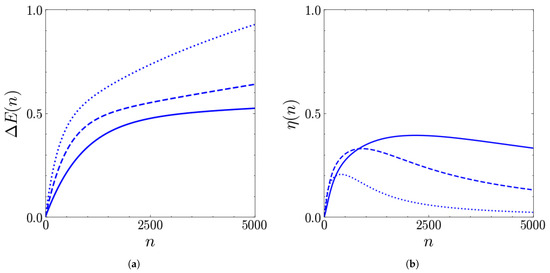
Figure 16.
Stored energy (in units of ) (a) and extraction efficiency (b) of the QB as functions of the number of collisions n for different values of (solid), (dashed), (dotted). The other parameters are , , and .
The interesting feature is that, for , the stored energy increases without stabilizing at a given value. Similarly to the coherent case, the behavior at higher can be interesting in view of maximizing the stored energy. However, in the incoherent case, increasing the duration has a negative effect on the extraction efficiency . Considering, for example, , we see that, even if the stored energy after 5000 collisions is almost doubled with respect to , has strongly reduced, so that there is no convenience in moving toward such high values of the collision time.
3.3. Experimental Feasibility
We conclude this section by addressing the features that real superconducting platforms must possess to implement the QB described in this work.
As stated above, the anharmonic multilevel QB can be realized through the superconducting circuit in Figure 1. In particular, the transmon regime guarantees an anharmonic and charge-insensitive multilevel structure that is suitable for our purposes. The interval usually identified as optimal for the transmon circuits is [24]. Here, we considered , a value that perfectly fits these bounds.
Assuming this and requiring to reach the typical operational frequency for a transmon GHz, [24,29,72] forces to be of the order of MHz. Considering again Figure 1, it is straightforward to show that, if the shunting capacitance is large enough, one has [24]
since . This implies that the required order of magnitude of is achieved by assuming pF. This value fits the typical range of capacitances used for superconducting circuits, which, due to their typical size, is often in the fF to low pF range [29,53].
In terms of one single ancillary qubit, it can be realized through a transmon circuit with a greater anharmonicity , so that, by initializing it as a superposition of its ground and first excited state, one can neglect its multilevel structure and describe it as an effective TLS realized addressing the two lower energetic states. In order to increase its anharmonicity, one could choose values of near the lower bound of the transmon range, namely, , a condition such that .
The capacitive coupling between two transmon circuits can be realized through the circuit represented in Figure 17 and further controlled in time, implementing quantum couplers [73,74,75]. By doing so, the coupling Hamiltonian takes the form [25]
with
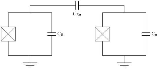
Figure 17.
Scheme of two capacitively coupled transmon circuits. and represent the shunting capacitance of the transmon QB and the transmon ancilla, respectively, whereas is the capacitance employed to couple them. The SQUID of each transmon has been denoted with the crossed boxes.
Within the TLS assumption for the ancillary transmon circuit, we can project in the basis , where and represent the ground and first excited states of the ancilla, respectively, obtaining
Direct numerical calculations of these coefficients show that the diagonal terms are negligible when compared with off-diagonal terms, so that one can safely assume
Thus, the resulting ratio between the coupling and the plasma frequency takes the form
Assuming , one obtains
Considering that , in order to work in the coupling regime explored in Section 3.1.1, one needs . Assuming pF, the required coupling capacitance reaches values of fF, which again fit the typical range for the capacitance of superconducting circuits mentioned above.
With the parameters discussed above, the duration is of the order of a few nanoseconds. This value fits the standard manipulation times for superconducting circuits like transmons [24].
The realization of the sequential interaction between the transmon QB and a set of uncorrelated and non-interacting ancillary transmons can be implemented in two ways. The first and more direct one is to realize many identical ancillary transmons, to keep them isolated from each other, and to independently and sequentially couple them with the transmon battery in a configuration analogous to very highly coordinated quantum computers.
A problem that may arise in this case is the survival of quantum coherences on a set of qubits large enough to obtain a significant energy storage (400–1000 collisions, as previously seen). Indeed, the global charging time of the battery can be estimated at most as μs, corresponding to 1000 interactions of the order of nanoseconds. This time scale competes with the decoherence and dephasing times and of transmon circuits, which represent the time scales over which quantum coherences are suppressed by the system environment interaction and quantum phases are randomized. However, the usual parameters for transmon circuits lead to [24], so that the coherence of transmon ancillas can be maintained for more than one oscillation period without relevant losses.
The main problem of this direct approach is the possibility of realizing such a great number of qubits and keeping them isolated from each other. For this reason, one could be interested in exploring the possibility of realizing only a small number of ancillary qubits, each of which could be re-initialized to the same initial state after the interaction with the QB, in order to be reused after the battery has interacted with all of the ancillas. This would be even better in terms of the maintenance of ancillary quantum coherences, since they would only need to survive for a shorter time . In principle, this scheme could be brought to an extreme, considering only one ancilla (). This option, however, is not optimal since, during the time needed for the re-initialization, the charging stops. The realization of multiple ancillary qubits would guarantee continuous charging, while the used ancillas are progressively re-initialized.
Such a reuse protocol for ancillary qubits has been proposed very recently in [76] in a different quantum computing platform based on neutral atoms. The technical challenge would, therefore, be represented by the adaptation of this re-initialization process to the superconducting case.
4. Conclusions
In this work, we have characterized the charging and energy extraction efficiency of a quantum battery based on a superconducting quantum circuit in the transmon regime [52]. Through numerical analysis, we have shown that the charging realized by means of the sequential interaction of the quantum battery with independent and coherent ancillas leads to a (slightly damped) oscillating behavior as a function of the number of collisions. The functional dependence of the energy stored in the device on the battery–ancilla coupling and the coherence within the ancillas has been reconstructed through best fits. For a short enough duration of the collisions, this energy remains stably confined within the cosine potential well given by the Josephson energy of the transmon, and in correspondence with the first maxima of the oscillations, the energy stored in the device can be almost completely extracted as useful work. For longer times of interaction, the stored energy is greater but less stable. Moreover, it cannot be completely extracted. When the charging is realized by means of incoherent ancillas, the oscillations disappear, and the asymptotic value of the stored energy reached after a great number of collisions depends on the coupling and on the energy initially trapped in each ancilla.
The major differences between these two regimes could be understood starting from mean field considerations about the effective Hamiltonian experienced by the transmon. Indeed, if one considers the effective contribution coming from an averaging of the Hamiltonian over the ancillary state at the beginning of each collision, it is non-zero only in the presence of coherences (). Thus, in the absence of quantum coherence, higher-order moments must intervene to enhance the energy transfer to the battery, resulting in slower dynamics. A deeper understanding could be provided by recalling the results already discussed in the literature [44] for a harmonic oscillator quantum battery charged through a collisional charging scheme. Here, the discrete dynamics of the incoherent charging have been mapped into a classical discrete-time random walk, with the interference effects of quantum coherences leading to a quantum random walk, which is ultimately responsible for the speed-up of the battery charging.
The proposed scheme for a transmon quantum battery combines the possibility of reaching a high level of control over the energy storage with a great extraction efficiency. Moreover, its working point is in a regime of parameters within reach in current superconducting circuits. According to this, the present work can contribute to providing a robust theoretical background for future experimental implementations of quantum batteries in state-of-the-art solid-state platforms.
Author Contributions
Conceptualization, F.C. and D.F.; formal analysis, N.M.; writing—original draft preparation, N.M.; writing—review and editing, F.C.; supervision, D.F. All authors have read and agreed to the published version of the manuscript.
Funding
D.F. and N.M. acknowledge the contribution of the European Union-NextGenerationEU through the “Quantum Busses for Coherent Energy Transfer” (QUBERT) project in the framework of the Curiosity-Driven 2021 initiative of the University of Genova. F.C. and D.F. acknowledge the contribution of the European Union-NextGenerationEU through the “Solid State Quantum Batteries: Characterization and Optimization” (SoS-QuBa) project (Prot. 2022XK5CPX) in the framework of the PRIN 2022 initiative of the Italian Ministry of University (MUR) for the National Research Program (PNR). This project has been funded within the program “PNRR Missione 4-Componente 2-Investimento 1.1 Fondo per il Programma Nazionale di Ricerca e Progetti di Rilevante Interesse Nazionale (PRIN)”.
Data Availability Statement
The reported data have been obtained by an in-house-developed QuTip code. It will be provided upon reasonable request.
Acknowledgments
The authors would like to thank G. Benenti and M. Sassetti for their useful discussions. We also thank anonymous reviewers for their useful comments and suggestions.
Conflicts of Interest
The authors declare no conflicts of interest.
Abbreviations
The following abbreviations are used in this manuscript:
| QB | Quantum battery |
| TLS | Two-level system |
Appendix A. τ < τp
Appendix A.1. Coherent Charging
The results obtained by reducing the interaction duration below are shown in Figure A1 for the coherent case and for .
The oscillating dynamics of the QB, for both storage and extraction, become slower if the duration is decreased. Thus, in view of experimental implementations, there is no advantage in reaching the regime : it is challenging at the technical level and worsens the QB charging performance in terms of charging time, since a greater amount of collisions is needed to reach the top of the well.
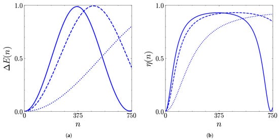
Figure A1.
Stored energy (in units of ) (a) and extraction efficiency (b) as functions of the number of collisions n for (solid), (dashed), (dotted). The other parameters are , , , .
Appendix A.2. Incoherent Charging
In terms of the incoherent case, the results obtained for are shown in Figure A2. As in the coherent case, the charging is slower at smaller values of . One interesting fact is that the long-time value of efficiency for is higher than the corresponding value for . Since the long-term stored energy is comparable, one could consider, despite the technical challenges, slightly reducing the duration of the collisions to enhance the extraction performances.
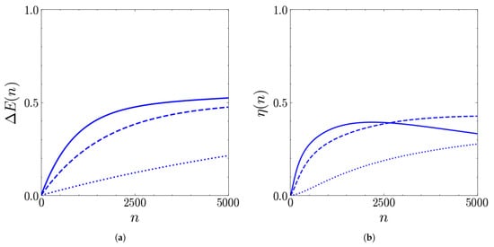
Figure A2.
Stored energy (in units of ) (a) and extraction efficiency (b) as functions of the number of collisions n for (solid), (dashed), (dotted). The other parameters are , , , .
Appendix B. Considerations About Intermediate of c
The results obtained for the case are shown in Figure A3 for . As expected, small deviations from the condition cause a slight reduction in the frequency of stored energy oscillations, without disruptive effects on their maxima and the extraction efficiency. Analogous results are found for the other values of q already analyzed.
This is of great relevance since it implies that one can afford to lose a fraction of ancillary quantum coherences, for example, due to decoherence phenomena, without compromising the battery functioning.
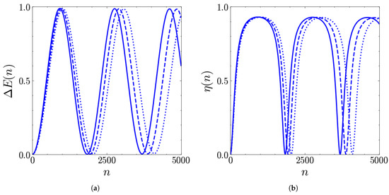
Figure A3.
Stored energy (in units of ) (a) and extraction efficiency (b) as functions of the number of collisions n for (solid), (dashed), (dotted). The other parameters are , , , .
References
- Koch, C.P.; Boscain, U.; Calarco, T.; Dirr, G.; Filipp, S.; Glaser, S.J.; Kosloff, R.; Montangero, S.; Schulte-Herbrüggen, T.; Sugny, D.; et al. Quantum optimal control in quantum technologies. Strategic report on current status, visions and goals for research in Europe. EPJ Quantum Technol. 2022, 9, 19. [Google Scholar] [CrossRef]
- Ezratty, O. Understanding Quantum Technologies 2024. arXiv 2024. [Google Scholar] [CrossRef]
- Quach, J.; Cerullo, G.; Virgili, T. Quantum batteries: The future of energy storage? Joule 2023, 7, 2195–2200. [Google Scholar] [CrossRef]
- Campaioli, F.; Gherardini, S.; Quach, J.Q.; Polini, M.; Andolina, G.M. Colloquium: Quantum batteries. Rev. Mod. Phys. 2024, 96, 031001. [Google Scholar] [CrossRef]
- Alicki, R.; Fannes, M. Entanglement boost for extractable work from ensembles of quantum batteries. Phys. Rev. E 2013, 87, 042123. [Google Scholar] [CrossRef]
- Le, T.P.; Levinsen, J.; Modi, K.; Parish, M.M.; Pollock, F.A. Spin-chain model of a many-body quantum battery. Phys. Rev. A 2018, 97, 022106. [Google Scholar] [CrossRef]
- Rossini, D.; Andolina, G.M.; Polini, M. Many-body localized quantum batteries. Phys. Rev. B 2019, 100, 115142. [Google Scholar] [CrossRef]
- Rossini, D.; Andolina, G.M.; Rosa, D.; Carrega, M.; Polini, M. Quantum Advantage in the Charging Process of Sachdev-Ye-Kitaev Batteries. Phys. Rev. Lett. 2020, 125, 236402. [Google Scholar] [CrossRef]
- Grazi, R.; Sacco Shaikh, D.; Sassetti, M.; Traverso Ziani, N.; Ferraro, D. Controlling Energy Storage Crossing Quantum Phase Transitions in an Integrable Spin Quantum Battery. Phys. Rev. Lett. 2024, 133, 197001. [Google Scholar] [CrossRef]
- Catalano, A.; Giampaolo, S.; Morsch, O.; Giovannetti, V.; Franchini, F. Frustrating Quantum Batteries. PRX Quantum 2024, 5, 030319. [Google Scholar] [CrossRef]
- Porta, S.; Cavaliere, F.; Sassetti, M.; Traverso Ziani, N. Topological classification of dynamical quantum phase transitions in the xy chain. Sci. Rep. 2020, 10, 12766. [Google Scholar] [CrossRef] [PubMed]
- Grazi, R.; Cavaliere, F.; Sassetti, M.; Ferraro, D.; Traverso Ziani, N. Charging free fermion quantum batteries. Chaos Solitons Fractals 2025, 196, 116383. [Google Scholar] [CrossRef]
- Lu, Z.G.; Tian, G.; Lü, X.Y.; Shang, C. Topological Quantum Batteries. Phys. Rev. Lett. 2025, 134, 180401. [Google Scholar] [CrossRef] [PubMed]
- Ferraro, D.; Campisi, M.; Andolina, G.M.; Pellegrini, V.; Polini, M. High-Power Collective Charging of a Solid-State Quantum Battery. Phys. Rev. Lett. 2018, 120, 117702. [Google Scholar] [CrossRef]
- Eckhardt, C.J.; Passetti, G.; Othman, M.; Karrasch, C.; Cavaliere, F.; Sentef, M.A.; Kennes, D.M. Quantum Floquet engineering with an exactly solvable tight-binding chain in a cavity. Commun. Phys. 2022, 5, 122. [Google Scholar] [CrossRef]
- Quach, J.Q.; McGhee, K.E.; Ganzer, L.; Rouse, D.M.; Lovett, B.W.; Gauger, E.M.; Keeling, J.; Cerullo, G.; Lidzey, D.G.; Virgili, T. Superabsorption in an organic microcavity: Toward a quantum battery. Sci. Adv. 2022, 8, eabk3160. [Google Scholar] [CrossRef]
- Carrasco, J.; Maze, J.R.; Hermann-Avigliano, C.; Barra, F. Collective enhancement in dissipative quantum batteries. Phys. Rev. E 2022, 105, 064119. [Google Scholar] [CrossRef]
- Dou, F.Q.; Lu, Y.Q.; Wang, Y.J.; Sun, J.A. Extended Dicke quantum battery with interatomic interactions and driving field. Phys. Rev. B 2022, 105, 115405. [Google Scholar] [CrossRef]
- Gemme, G.; Andolina, G.M.; Pellegrino, F.M.D.; Sassetti, M.; Ferraro, D. Off-Resonant Dicke Quantum Battery: Charging by Virtual Photons. Batteries 2023, 9, 197. [Google Scholar] [CrossRef]
- Wang, L.; Liu, S.Q.; Wu, F.l.; Fan, H.; Liu, S.Y. Deep strong charging in a multiphoton anisotropic Dicke quantum battery. Phys. Rev. A 2024, 110, 042419. [Google Scholar] [CrossRef]
- Yang, D.L.; Yang, F.M.; Dou, F.Q. Three-level Dicke quantum battery. Phys. Rev. B 2024, 109, 235432. [Google Scholar] [CrossRef]
- Erdman, P.A.; Andolina, G.M.; Giovannetti, V.; Noé, F. Reinforcement Learning Optimization of the Charging of a Dicke Quantum Battery. Phys. Rev. Lett. 2024, 133, 243602. [Google Scholar] [CrossRef] [PubMed]
- Hymas, K.; Muir, J.B.; Tibben, D.; van Embden, J.; Hirai, T.; Dunn, C.J.; Gómez, D.E.; Hutchison, J.A.; Smith, T.A.; Quach, J.Q. Experimental demonstration of a scalable room-temperature quantum battery. arXiv 2025. [Google Scholar] [CrossRef]
- Koch, J.; Yu, T.M.; Gambetta, J.; Houck, A.A.; Schuster, D.I.; Majer, J.; Blais, A.; Devoret, M.H.; Girvin, S.M.; Schoelkopf, R.J. Charge-insensitive qubit design derived from the Cooper pair box. Phys. Rev. A 2007, 76, 042319. [Google Scholar] [CrossRef]
- Krantz, P.; Kjaergaard, M.; Yan, F.; Orlando, T.P.; Gustavsson, S.; Oliver, W.D. A quantum engineer’s guide to superconducting qubits. App. Phys. Rev. 2019, 6, 021318. [Google Scholar] [CrossRef]
- Hu, C.K.; Qiu, J.; Souza, P.J.P.; Yuan, J.; Zhou, Y.; Zhang, L.; Chu, J.; Pan, X.; Hu, L.; Li, J.; et al. Optimal charging of a superconducting quantum battery. Quantum Sci. Technol. 2022, 7, 045018. [Google Scholar] [CrossRef]
- Gemme, G.; Grossi, M.; Vallecorsa, S.; Sassetti, M.; Ferraro, D. Qutrit quantum battery: Comparing different charging protocols. Phys. Rev. Res. 2024, 6, 023091. [Google Scholar] [CrossRef]
- Cavaliere, F.; Gemme, G.; Benenti, G.; Ferraro, D.; Sassetti, M. Dynamical blockade of a reservoir for optimal performances of a quantum battery. Commun. Phys. 2025, 8, 76. [Google Scholar] [CrossRef]
- Blais, A.; Grimsmo, A.L.; Girvin, S.M.; Wallraff, A. Circuit quantum electrodynamics. Rev. Mod. Phys. 2021, 93, 025005. [Google Scholar] [CrossRef]
- Hovhannisyan, K.V.; Barra, F.; Imparato, A. Charging assisted by thermalization. Phys. Rev. Res. 2020, 2, 033413. [Google Scholar] [CrossRef]
- Rodríguez, R.R.; Ahmadi, B.; Mazurek, P.; Barzanjeh, S.; Alicki, R.; Horodecki, P. Catalysis in charging quantum batteries. Phys. Rev. A 2023, 107, 042419. [Google Scholar] [CrossRef]
- Benenti, G.; Palma, G.M. Reversible and irreversible dynamics of a qubit interacting with a small environment. Phys. Rev. A 2007, 75, 052110. [Google Scholar] [CrossRef]
- Ziman, M.; Bužek, V. All (qubit) decoherences: Complete characterization and physical implementation. Phys. Rev. A 2005, 72, 022110. [Google Scholar] [CrossRef]
- Ciccarello, F.; Lorenzo, S.; Giovannetti, V.; Palma, G.M. Quantum collision models: Open system dynamics from repeated interactions. Phys. Rep. 2022, 954, 1–70. [Google Scholar] [CrossRef]
- Cusumano, S. Quantum Collision Models: A Beginner Guide. Entropy 2022, 24, 1258. [Google Scholar] [CrossRef] [PubMed]
- Campbell, S.; Vacchini, B. Collision models in open system dynamics: A versatile tool for deeper insights? Europhys. Lett. 2021, 133, 60001. [Google Scholar] [CrossRef]
- Strasberg, P.; Schaller, G.; Brandes, T.; Esposito, M. Quantum and Information Thermodynamics: A Unifying Framework Based on Repeated Interactions. Phys. Rev. X 2017, 7, 021003. [Google Scholar] [CrossRef]
- Shaghaghi, V.; Palma, G.M.; Benenti, G. Extracting work from random collisions: A model of a quantum heat engine. Phys. Rev. E 2022, 105, 034101. [Google Scholar] [CrossRef]
- Breuer, H.P.; Petruccione, F. The Theory of Open Quantum Systems; Oxford University: Oxford, UK, 2006. [Google Scholar] [CrossRef]
- Weiss, U. Quantum Dissipative Systems, 4th ed.; World Scientific: Singapore, 2012. [Google Scholar] [CrossRef]
- Morrone, D.; Rossi, M.A.C.; Smirne, A.; Genoni, M.G. Charging a quantum battery in a non-Markovian environment: A collisional model approach. Quantum Sci. Technol. 2023, 8, 035007. [Google Scholar] [CrossRef]
- Barra, F. Dissipative Charging of a Quantum Battery. Phys. Rev. Lett. 2019, 122, 210601. [Google Scholar] [CrossRef]
- Carrega, M.; Crescente, A.; Ferraro, D.; Sassetti, M. Dissipative dynamics of an open quantum battery. New J. Phys. 2020, 22, 083085. [Google Scholar] [CrossRef]
- Seah, S.; Perarnau-Llobet, M.; Haack, G.; Brunner, N.; Nimmrichter, S. Quantum Speed-Up in Collisional Battery Charging. Phys. Rev. Lett. 2021, 127, 100601. [Google Scholar] [CrossRef]
- Landi, G.T. Battery Charging in Collision Models with Bayesian Risk Strategies. Entropy 2021, 23, 1627. [Google Scholar] [CrossRef] [PubMed]
- Shaghaghi, V.; Singh, V.; Benenti, G.; Rosa, D. Micromasers as quantum batteries. Quantum Sci. Technol. 2022, 7, 04LT01. [Google Scholar] [CrossRef]
- Salvia, R.; Perarnau-Llobet, M.; Haack, G.; Brunner, N.; Nimmrichter, S. Quantum advantage in charging cavity and spin batteries by repeated interactions. Phys. Rev. Res. 2023, 5, 013155. [Google Scholar] [CrossRef]
- Shaghaghi, V.; Singh, V.; Carrega, M.; Rosa, D.; Benenti, G. Lossy Micromaser Battery: Almost Pure States in the Jaynes–Cummings Regime. Entropy 2023, 25, 430. [Google Scholar] [CrossRef]
- Rodríguez, C.; Rosa, D.; Olle, J. Artificial intelligence discovery of a charging protocol in a micromaser quantum battery. Phys. Rev. A 2023, 108, 042618. [Google Scholar] [CrossRef]
- Haroche, S. Nobel Lecture: Controlling photons in a box and exploring the quantum to classical boundary. Rev. Mod. Phys. 2013, 85, 1083–1102. [Google Scholar] [CrossRef]
- Slosser, J.J.; Meystre, P.; Braunstein, S.L. Harmonic oscillator driven by a quantum current. Phys. Rev. Lett. 1989, 63, 934–937. [Google Scholar] [CrossRef]
- Dou, F.Q.; Yang, F.M. Superconducting transmon qubit-resonator quantum battery. Phys. Rev. A 2023, 107, 023725. [Google Scholar] [CrossRef]
- Roth, T.E.; Ma, R.; Chew, W.C. The Transmon Qubit for Electromagnetics Engineers: An introduction. IEEE Antennas Propag. Mag. 2023, 65, 8–20. [Google Scholar] [CrossRef]
- Devoret, M.H.; Wallraff, A.; Martinis, J.M. Superconducting Qubits: A Short Review. arXiv 2004. [Google Scholar] [CrossRef]
- Jaklevic, R.C.; Lambe, J.; Silver, A.H.; Mercereau, J.E. Quantum Interference Effects in Josephson Tunneling. Phys. Rev. Lett. 1964, 12, 159–160. [Google Scholar] [CrossRef]
- SQUIDs: Theory and Applications. In Physics and Applications of the Josephson Effect; John Wiley & Sons, Ltd.: Hoboken, NJ, USA, 1982; Chapter 13; pp. 383–445. [CrossRef]
- Pietikäinen, I.; Tuorila, J.; Golubev, D.S.; Paraoanu, G.S. Photon blockade and the quantum-to-classical transition in the driven-dissipative Josephson pendulum coupled to a resonator. Phys. Rev. A 2019, 99, 063828. [Google Scholar] [CrossRef]
- Peano, V.; Thorwart, M. Dynamics of the quantum Duffing oscillator in the driving induced bistable regime. Chem. Phys. 2006, 322, 135–143. [Google Scholar] [CrossRef][Green Version]
- Serban, I.; Wilhelm, F.K. Dynamical Tunneling in Macroscopic Systems. Phys. Rev. Lett. 2007, 99, 137001. [Google Scholar] [CrossRef] [PubMed]
- Vierheilig, C.; Grifoni, M. The dissipative quantum Duffing oscillator: A comparison of Floquet-based approaches. Chem. Phys. 2010, 375, 216–226. [Google Scholar] [CrossRef]
- Buluta, I.; Ashhab, S.; Nori, F. Natural and artificial atoms for quantum computation. Rep. Prog. Phys. 2011, 74, 104401. [Google Scholar] [CrossRef]
- Johansson, J.; Nation, P.; Nori, F. QuTiP: An open-source Python framework for the dynamics of open quantum systems. Comput. Phys. Commun. 2012, 183, 1760–1772. [Google Scholar] [CrossRef]
- Andolina, G.M.; Farina, D.; Mari, A.; Pellegrini, V.; Giovannetti, V.; Polini, M. Charger-mediated energy transfer in exactly solvable models for quantum batteries. Phys. Rev. B 2018, 98, 205423. [Google Scholar] [CrossRef]
- Binder, F.C.; Vinjanampathy, S.; Modi, K.; Goold, J. Quantacell: Powerful charging of quantum batteries. New J. Phys. 2015, 17, 075015. [Google Scholar] [CrossRef]
- Bhattacharjee, S.; Dutta, A. Quantum thermal machines and batteries. Eur. Phys. J. B 2021, 94, 239. [Google Scholar] [CrossRef]
- Pusz, W.; Woronowicz, S. Passive states and KMS states for general quantum systems. Commun. Math. Phys. 1978, 58, 273–290. [Google Scholar] [CrossRef]
- Allahverdyan, A.E.; Balian, R.; Nieuwenhuizen, T.M. Maximal work extraction from finite quantum systems. Europhys. Lett. 2004, 67, 565. [Google Scholar] [CrossRef]
- Barra, F.; Hovhannisyan, K.V.; Imparato, A. Quantum batteries at the verge of a phase transition. New J. Phys. 2022, 24, 015003. [Google Scholar] [CrossRef]
- Frisk Kockum, A.; Miranowicz, A.; De Liberato, S.; Savasta, S.; Nori, F. Ultrastrong coupling between light and matter. Nat. Rev. Phys. 2019, 1, 19–40. [Google Scholar] [CrossRef]
- Crescente, A.; Carrega, M.; Sassetti, M.; Ferraro, D. Ultrafast charging in a two-photon Dicke quantum battery. Phys. Rev. B 2020, 102, 245407. [Google Scholar] [CrossRef]
- Crescente, A.; Ferraro, D.; Sassetti, M. Boosting energy transfer between quantum devices through spectrum engineering in the dissipative ultrastrong coupling regime. Phys. Rev. Res. 2024, 6, 023092. [Google Scholar] [CrossRef]
- Kockum, A.F.; Nori, F. Quantum Bits with Josephson Junctions. In Fundamentals and Frontiers of the Josephson Effect; Tafuri, F., Ed.; Springer International Publishing: Cham, Switzerland, 2019; pp. 703–741. [Google Scholar] [CrossRef]
- Sete, E.A.; Chen, A.Q.; Manenti, R.; Kulshreshtha, S.; Poletto, S. Floating Tunable Coupler for Scalable Quantum Computing Architectures. Phys. Rev. Appl. 2021, 15, 064063. [Google Scholar] [CrossRef]
- Campbell, D.L.; Kamal, A.; Ranzani, L.; Senatore, M.; LaHaye, M.D. Modular Tunable Coupler for Superconducting Circuits. Phys. Rev. Appl. 2023, 19, 064043. [Google Scholar] [CrossRef]
- Heunisch, L.; Eichler, C.; Hartmann, M.J. Tunable coupler to fully decouple and maximally localize superconducting qubits. Phys. Rev. Appl. 2023, 20, 064037. [Google Scholar] [CrossRef]
- Muniz, J.A.; Crow, D.; Kim, H.; Kindem, J.M.; Cairncross, W.B.; Ryou, A.; Bohdanowicz, T.C.; Chen, C.A.; Ji, Y.; Jones, A.M.W.; et al. Repeated ancilla reuse for logical computation on a neutral atom quantum computer. arXiv 2025. [Google Scholar] [CrossRef]
Disclaimer/Publisher’s Note: The statements, opinions and data contained in all publications are solely those of the individual author(s) and contributor(s) and not of MDPI and/or the editor(s). MDPI and/or the editor(s) disclaim responsibility for any injury to people or property resulting from any ideas, methods, instructions or products referred to in the content. |
© 2025 by the authors. Licensee MDPI, Basel, Switzerland. This article is an open access article distributed under the terms and conditions of the Creative Commons Attribution (CC BY) license (https://creativecommons.org/licenses/by/4.0/).