1. Introduction
The global need for sustainable and efficient energy storage systems has grown significantly in recent years due to the rapid integration of renewable energy sources and the electrification of various sectors, including transportation and grid-level storage. Among the wide range of energy storage technologies, lithium-ion batteries (LIBs) have become the market leader, thanks to their high energy density, well-established technology, and extensive applications. However, the reliance on flammable organic electrolytes and the limited availability of lithium resources presents substantial challenges, including safety risks and concerns about resource sustainability [
1,
2]. These issues have driven intensified research into alternative energy storage solutions that are not only safer but also cost-effective and environmentally friendly.
Aqueous zinc-ion batteries (AZIBs) have emerged as a strong candidate, benefiting from the advantages of zinc metal as an anode material. Zinc offers several benefits, including high theoretical capacity (820 mAh g
−1), low redox potential (−0.76 V vs. SHE), and abundant natural reserves [
3,
4,
5]. Additionally, the use of aqueous electrolytes in ZIBs addresses the safety challenges of LIBs, removing the risks of fire and explosion while also reducing production costs [
6,
7]. Despite these advantages, the commercialization of ZIBs is hindered by critical challenges mainly associated with the zinc metal anode. The zinc anode is highly vulnerable to dendrite growth, hydrogen evolution reactions (HER), and surface corrosion during repeated charge–discharge cycles, resulting in early battery failure and decreased energy efficiency [
8,
9].
To overcome these obstacles, researchers have proposed various strategies, including optimizing electrolytes [
10,
11], designing advanced host structures [
12,
13,
14,
15], and modifying the surface of zinc electrodes [
16,
17,
18]. Among these approaches, applying surface coatings has proven to be a highly effective and versatile solution. Coating the zinc metal surface with protective layers can isolate the anode from direct interaction with the aqueous electrolyte, suppress dendrite formation, and minimize undesirable side reactions [
16,
17,
18]. Carbon-based coatings have attracted considerable interest due to their excellent electrical conductivity, chemical stability, and adjustable properties [
19,
20,
21]. Furthermore, carbon materials are readily available and can be engineered to preserve the mechanical and electrochemical stability of the Zn anode [
22].
Diamond-like carbon (DLC) coatings, known for their unique combination of high mechanical hardness, chemical inertness, and tunable electrical conductivity, have demonstrated significant success in stabilizing reactive metal anodes such as lithium by mitigating dendrite formation and suppressing parasitic interfacial reactions [
23,
24,
25]. Inspired by these advances in non-aqueous systems, recent studies have begun to explore the potential of DLC coatings in AZIBs, where similar interfacial challenges such as hydrogen evolution, Zn corrosion, and dendritic growth remain critical barriers to practical implementation [
26,
27]. The dense and conformal nature of DLC enables it to act as a robust interlayer that can isolate the Zn surface from direct contact with the aqueous electrolyte, thus mitigating electrochemical side reactions and minimizing gas evolution. [
26] Also, the tunable ratio of sp
2/sp
3-hybridized carbon bonds allows the DLC layer to retain moderate electronic conductivity while simultaneously guiding uniform Zn
2+ flux and deposition [
25,
28]. While carbonaceous coatings have been preliminarily applied to Zn anodes, the application of amorphous DLC coatings, designed for high impermeability and potentially improved mechanical properties, remains largely unexplored in AZIBs [
26,
27,
28]. This approach represents a promising strategy for achieving a multifunctional interfacial layer that physically shields the Zn surface, electrochemically regulates nucleation, and chemically withstands aqueous corrosion. Therefore, the application of DLC coatings to Zn anodes represents a novel and rational extension of a proven interfacial engineering strategy, with the potential to unlock long-term cycling stability and safety in high-performance aqueous Zn-based energy storage systems. While these materials show promise for improving performance, challenges remain. For example, thick coatings often increase interfacial resistance and reduce the energy density of the battery [
29]. In contrast, ultrathin carbon coatings have demonstrated outstanding performance by enhancing surface wettability, facilitating charge transfer, and maintaining uniform zinc deposition [
19,
20]. However, despite their potential, research on ultrathin DLC coatings for zinc anodes remains relatively limited, and a more detailed understanding of their impact on electrochemical performance is needed.
In this study, we investigated the effect of DLC-coated Zn anodes on the electrochemical performances of AZIBs. The DLC coating on Zn anodes significantly suppresses dendrite growth, thereby enhancing the cyclic stability of AZIBs. Through systematic analysis, we demonstrate that the DLC-coated zinc anode achieves an impressive cycling life of over 160 h, far exceeding the performance of bare zinc anodes. Also, a full-cell configuration using a (NH4)2V6O16·1.5H2O (AVNF) cathode confirms the practical applicability of this approach, achieving superior capacity retention over 900 cycles. This work provides a detailed understanding of the role of ultrathin DLC coatings in stabilizing Zn anodes for aqueous ZIBs.
2. Experimental Procedure
All chemical reagents, including vanadium pentoxide (V2O5, 99%) and ammonium persulfate ((NH4)2S2O8, 98%), were purchased from Sigma-Aldrich (St. Louis, MO, USA). Deionized (DI) water (18.2 MΩ·cm, Milli-Q Plus system, Millipore, France) was used as the solvent for the synthesis of an ammonium vanadate nanofiber (AVNF) intercalated with NH4+ and H2O as a cathode material. A yellow dispersion was prepared by dissolving 0.4 g of vanadium pentoxide (V2O5, 2.2 mmol) and 0.2 g of ammonium persulfate (APS, 0.88 mmol) in 100 mL of DI water. A sonicator (20 kHz, 500 W) equipped with a titanium tip was immersed into the dispersion to a depth of 1.5 cm, and the mixture was sonicated for 30 min. After the ultrasonic reaction, the color of the solution changed from yellow to dark red. The AVNF was then separated through filtration and washed with ethanol and DI water. The resulting AVNF was dried in a vacuum oven at 60 °C for 12 h.
The DLC coating on the Zn anode was applied using a pulse-enhanced chemical vapor deposition (PECVD) system manufactured by iVEX. The chamber dimensions were 1000 mm in diameter and 1000 mm in height. The system was equipped with two 850 mm linear ion guns to ensure uniform coating of the substrate. The Zn anode was mounted on a jig capable of 10-axis rotation to achieve consistent coverage during deposition. Before the coating process, the chamber was evacuated to a base pressure of less than 5.0 × 10⁻⁵ Torr to minimize contamination. The coating process comprised two sequential steps. First, the Zn anode was subjected to argon plasma cleaning. High-purity argon gas (99.999%) was introduced at a flow rate of 60 sccm. The ion guns were operated at a current of 0.35 A and a voltage of 1800 V, while a pulsed DC bias of −100 V at a frequency of 150 kHz was applied to the substrate. The cleaning process lasted for 20 min to remove surface impurities and enhance adhesion of the DLC layer. Following the cleaning step, the DLC coating was applied using methane gas (CH4) with a purity of 97.0%, introduced at a flow rate of 70 sccm. The ion guns were set to a current of 0.4 A and a voltage of 1800 V, with the substrate bias maintained at −100 V using a pulsed DC frequency of 150 kHz. The coating was performed for different durations to achieve varying film thicknesses. Specifically, DLC1, DLC2, and DLC3 refer to samples coated for 1 min, 2 min, and 3 min, respectively.
The morphological characteristics and energy-dispersive spectroscopy (EDS) profiles of the synthesized AVNF and DLC-coated Zn were analyzed using a scanning electron microscope (SEM, Jeol, JSM-7610F PLUS, Tokyo, Japan). The crystal structure of the samples was determined via X-ray diffraction (XRD, Malvern Panalytical, Almelo, The Netherlands) using an Empyrean diffractometer. Also, the chemical nature and surface morphology of the DLC-coated Zn was analyzed using Raman spectroscopy (Raman, WEVE Co., Ltd., Seongnam-si, Gyeonggi-do, Republic of Korea) and Atomic Force Microscopy (AFM, Veeco, Nanoman, Plainview, NY, USA).
The cathode was prepared by mixing AVNF, carbon black (Super P, TIMCAL, Bodio, Switzerland), and polyvinylidene difluoride (PVDF, average MW ~534,000, Sigma-Aldrich, St. Louis, MO, USA) in a mass ratio of 7:2:1. The powders were dispersed in N-methylpyrrolidone (NMP, Sigma-Aldrich, St. Louis, MO, USA) and homogenized using a planetary centrifugal mixer (AR-100, Thinky Corporation, Tokyo, Japan) to form a uniform slurry. This slurry was coated onto a 10 μm thick SUS304 stainless-steel foil (Wellcos, Seoul, Republic of Korea) with a loading mass in the range of 1.0–1.2 mg. The aqueous electrolyte was prepared by dissolving 3 M zinc trifluoromethanesulfonate (Zn(OTf)2, Alfa Aesar, 98%, Ward Hill, MA, USA) in deionized water. A volume of 100 μL of the electrolyte was used for each cell. The AVNF//Zn and AVNF//DLC-coated Zn cells were assembled in CR2032 coin cell configurations using a glass fiber filter (GF/A, Whatman, Cytiva, Marlborough, MA, USA) as the separator.
All electrochemical measurements were conducted at room temperature (25 °C). The coin cells were tested using a battery cycler (WBCS 3000 L; WonATech, Seoul, Republic of Korea). Electrochemical impedance spectroscopy (EIS) was performed over a frequency range of 1 MHz to 0.1 Hz with an amplitude of 5 mV, using a potentiostat/galvanostat (PGSTAT302N, AUTOLAB, Utrecht, The Netherlands). The cells were cycled in a voltage range of 0.2–1.8 V, and their cycling performance was evaluated at a current density of 2 A g−1.
3. Results and Discussion
The XRD pattern of the AVNF through pre-intercalation of NH
4+ ions into V
2O
5 is presented in
Figure 1a. Compared to the XRD pattern of V
2O
5 corresponding to the orthorhombic structure of the Pmmm space group (JCPDS No. 72-0433) in our previous report, the XRD pattern of AVNF is well in agreement with a monoclinic structure of (NH
4)
2V
6O
16·1.5H
2O, which is in good agreement with JCPDS No. 51-0376. [
17]. The 2
θ positions of 10.8°, 14.4°, 17.4°, 21.5°, 22.3°, 25.8°, 27.0°, 28.0°, and 30.6° correspond to the (002), (200), (20−2), (004), (30−1), (110), (204), (112), and (006) planes, respectively. The morphology significantly changes to a nanofiber-like shape, as shown in
Figure 1b. The growth mechanism of AVNF fibers can be attributed to the olation and oxolation reactions of the precursors, facilitated by internal proton transfer within vanadium species six-coordinated by water molecules. [
17] At the optimal pH, the olation reaction in the solution proceeds at a faster rate than the oxolation reaction. This kinetic preference directs the growth of the precursors predominantly through olation, resulting in the fibrous morphology of AVNF [
30]. Also, EDS analysis shows a homogeneous distribution of elements including vanadium, oxygen, and nitrogen throughout the structure, as shown in
Figure 1c,d.
The thickness of the DLC coating can play an important role in determining the performance of zinc anodes in AZIB applications. An optimal DLC coating thickness can significantly enhance the lifespan, stability, and charge–discharge efficiency of the AZIB by maintaining consistent electrode performance. As shown in
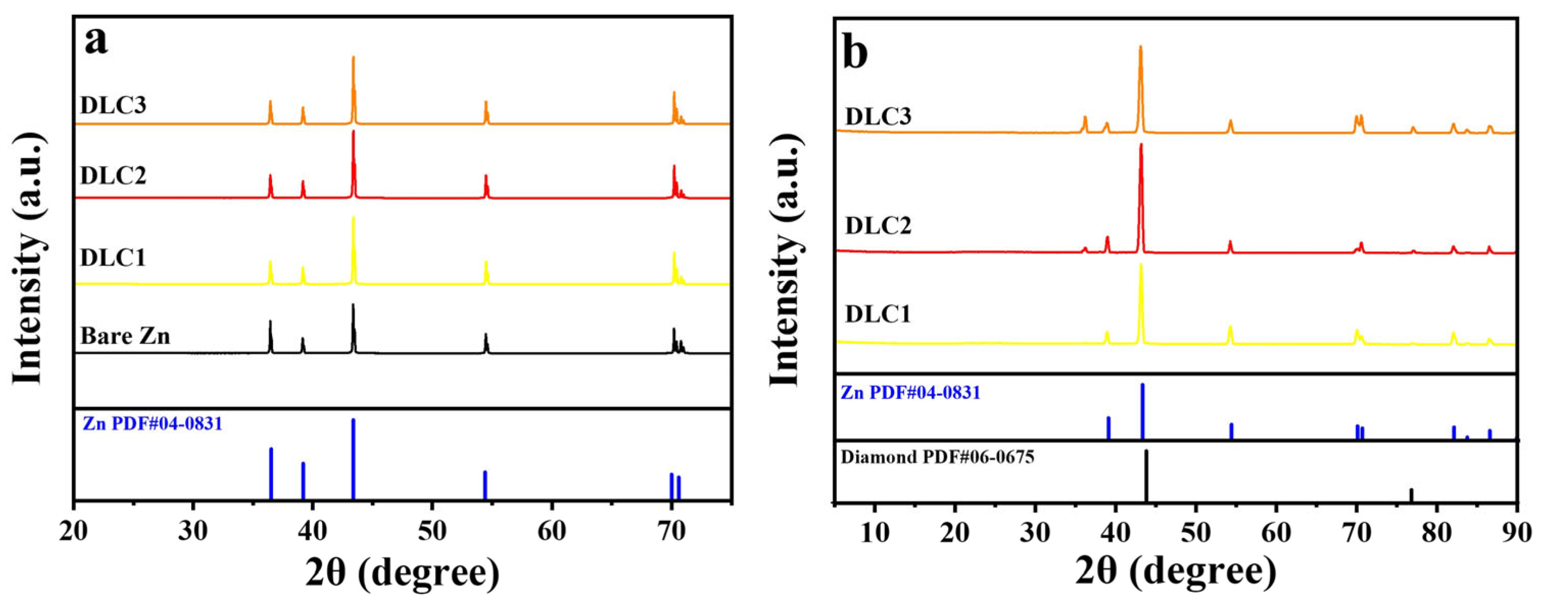
Figure 2, the thickness of the DLC1, DLC2, and DLC3 is approximately 10, 20, and 30 nm, respectively. To investigate the structure of the DLC on the zinc anode, materials analyses using XRD and GIXRD were performed. XRD patterns of bare zinc and DLC-coated zinc anodes are shown in
Figure 3a. All samples exhibited peak intensities at (002), (100), (101), (102), (103), and (110) planes, confirming the crystalline nature of the zinc anode (JCPDS: 36-1451). In order to further investigate the structure of the DLC coating layer, GIXRD was performed and analyzed as shown in
Figure 3b, which shows two peaks at around 44.05° and 75.25° corresponding to the (111) and (220) plane of diamond (JCPDS: 06-0675). Also, the peak with weak intensities located at 36° could be identified as a peak for carbon.
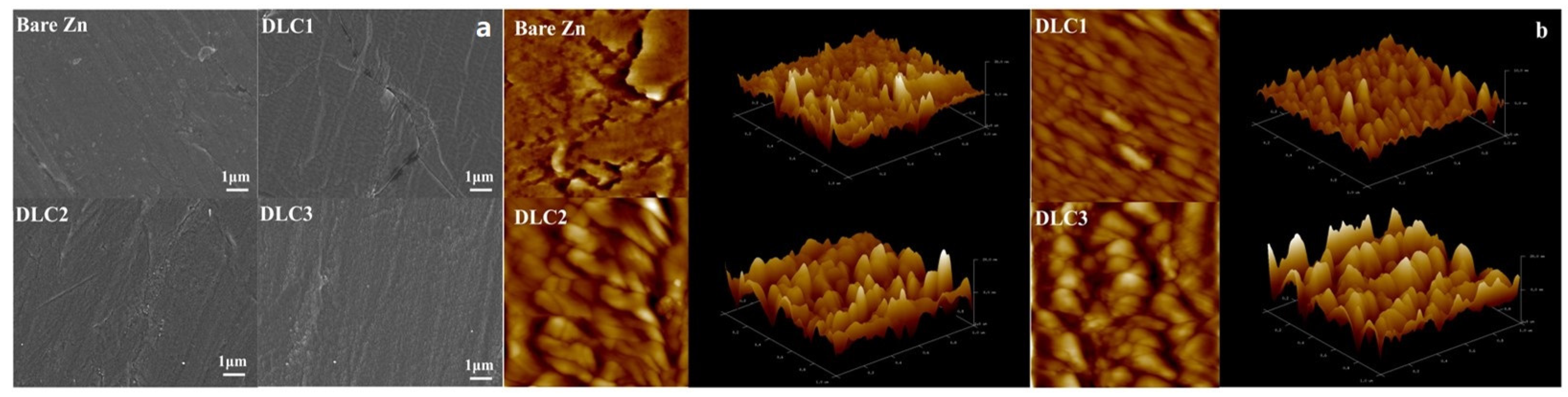
Figure 4 shows the surface morphology of the bare Zn and DLC-coated Zn electrodes. As shown in
Figure 4a, the SEM images reveal that the surface of the bare zinc anode exhibits smooth and uniform morphology. Following the deposition of DLC coatings, the overall surface morphology of the DLC-coated samples appears similar to that of bare zinc, indicating that the DLC films covered the zinc anode without introducing significant surface irregularities. As shown in
Figure 4b, bare Zn exhibits a relatively rough and irregular surface, with R
a and R
q values of 4.03 nm and 5.81 nm, respectively. Upon coating with DLC, the surface becomes smoother, particularly for DLC1, which presents the lowest roughness values (R
a = 2.74 nm, R
q = 3.66 nm), indicating an effective reduction in nanoscale protrusions. However, further increases in DLC thickness led to a gradual rise in roughness, possibly due to increased internal stress or nanoscale agglomeration during film deposition. Roughness parameters (R
a and R
q) are summarized in
Table 1.
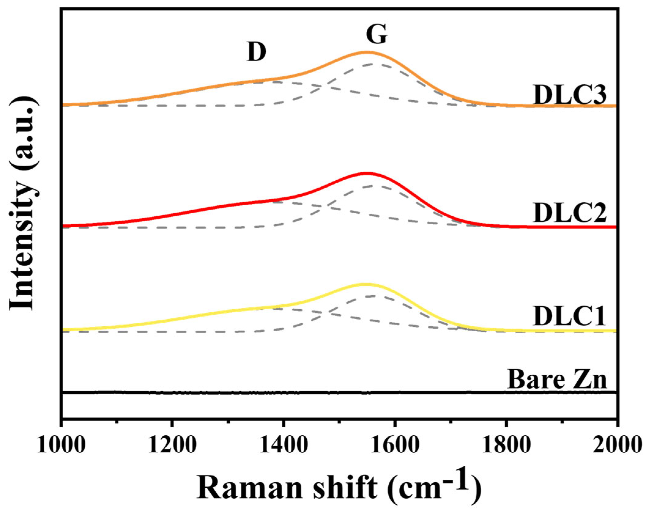
Raman spectroscopy was conducted to further characterize the structural features of the DLC coatings, and the results are presented in
Figure 5. No significant peaks were observed in the bare zinc anode in the Raman spectra, indicating the absence of carbon-based materials on its surface. In contrast, DLC-coated zinc samples exhibited two prominent peaks, the D-band (~1350 cm
−1) and the G-band (~1580 cm
−1), which provide valuable insights into the structural characteristics of the DLC films. The D-band is associated with the disorder in the carbon structure and arises from the sp
2 carbon atoms in disordered graphite and amorphous carbon regions, which is typical for amorphous carbon materials like DLC [
31]. On the other hand, the G-band corresponds to the stretching vibrations of sp
2 carbon–carbon bonds in graphitic domains, indicating the presence of sp
2-hybridized carbon atoms within the DLC films. The coexistence of the D-band and G-band in the DLC coatings reflects the hybrid nature of DLC, which contains both sp
2 (graphitic) and sp
3 (diamond-like) carbon phases. The relative intensities of the D-band (I
D) and G-band (I
G), expressed as the I
D/I
G ratio, provide critical information about the structural composition of the DLC coatings. A higher I
D/I
G ratio indicates a greater degree of disorder within the carbon structure, suggesting a higher fraction of sp
2-bonded carbon [
32]. Conversely, a lower I
D/I
G ratio suggests a more graphitic or ordered structure with a balanced sp
2/sp
3 ratio. As shown in
Table 2, the intensity ratio (I
D/I
G) decreased progressively from 0.761 for DLC1 to 0.738 for DLC2 and 0.731 for DLC3, suggesting a reduction in structural disorder and an increase in sp
3-hybridized carbon content as the coating thickness increased.
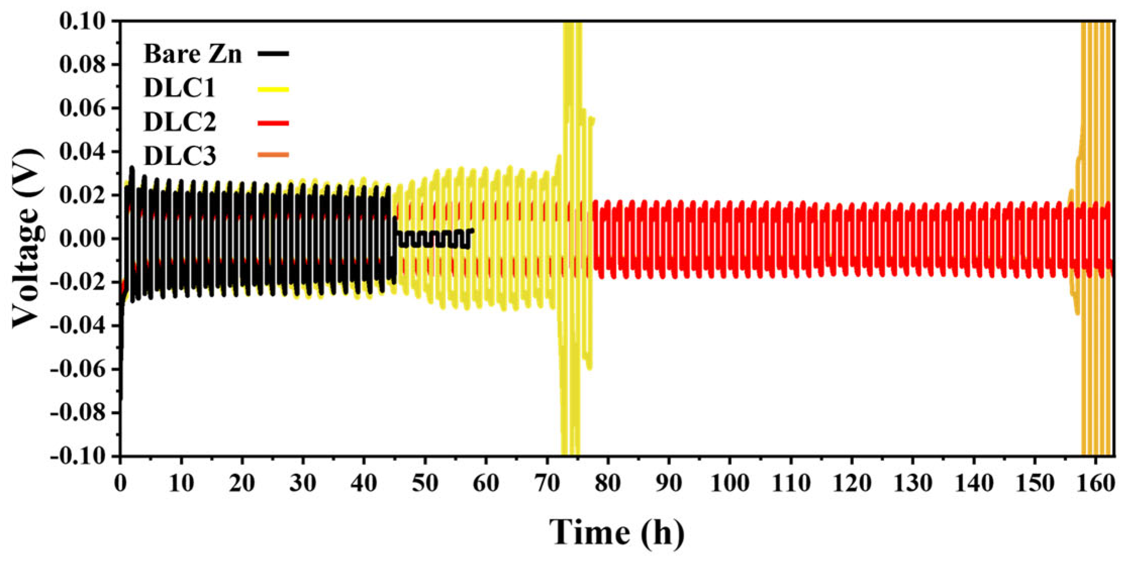
The symmetrical cell using DLC2 demonstrates the most stable and prolonged cycling performance over 160 h, as shown in
Figure 6. Also, EIS was conducted to evaluate the interfacial resistance of bare zinc and DLC-coated zinc anodes. The Nyquist plots of the samples are clearly presented in
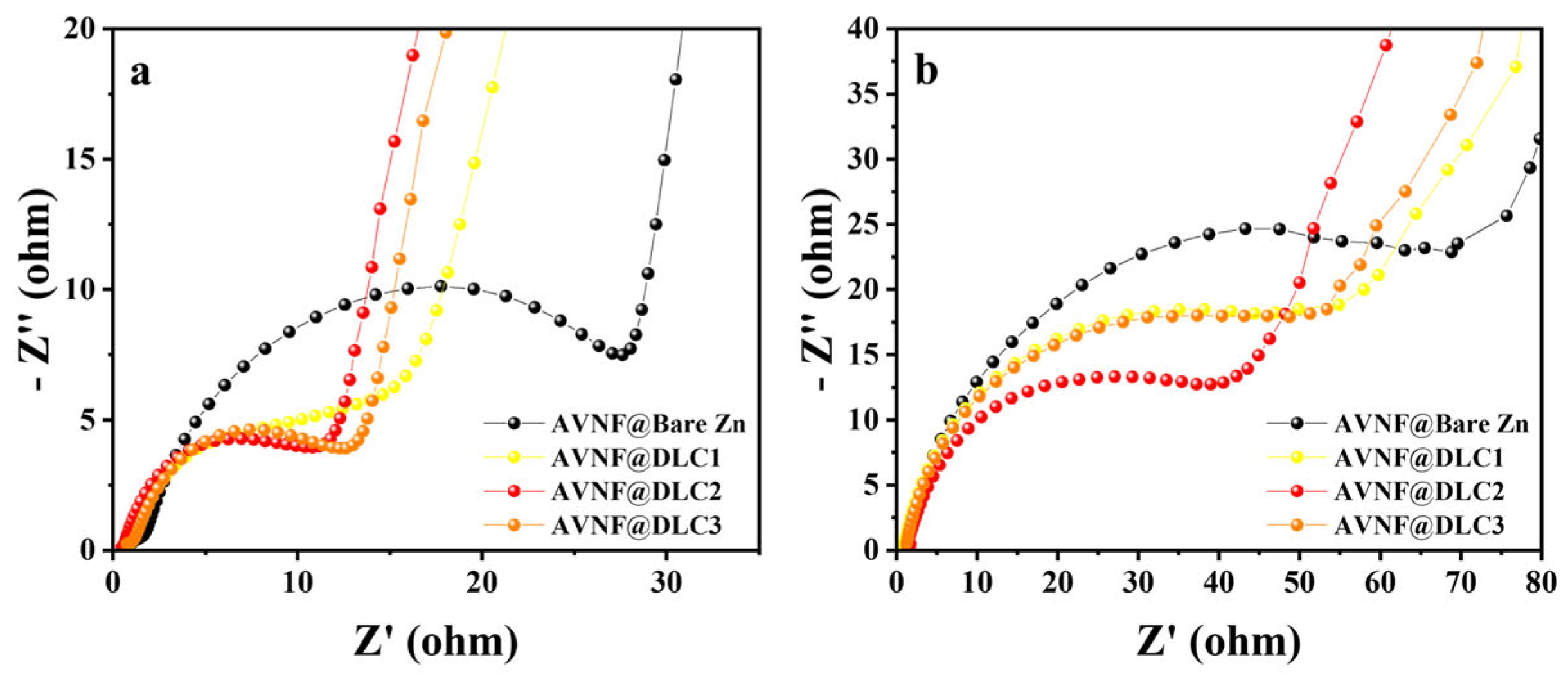
Figure 7. The Nyquist plot for the bare zinc anode shows a large semicircle in the high-to-medium frequency range, indicating substantial interfacial resistance. This high resistance is likely caused by the irregular zinc surface and the formation of passivation layers or dendrites during electrochemical cycling, which impede charge transfer at the interface [
33]. In contrast, the DLC-coated zinc anodes display smaller semicircles, reflecting reduced interfacial resistance. Among the DLC-coated samples, the degree of resistance reduction varies depending on the thickness of the coating. DLC2 exhibits the smallest semicircle, indicating the lowest interfacial resistance, followed by DLC3 and then DLC1. This trend highlights the critical role of DLC coating thickness in optimizing interfacial properties. A thinner coating, as in DLC1, may not provide sufficient coverage to suppress zinc surface irregularities, while a thicker coating, as in DLC3, could introduce additional electronic resistance. DLC2 appears to achieve an optimal balance, resulting in the most efficient charge transfer.
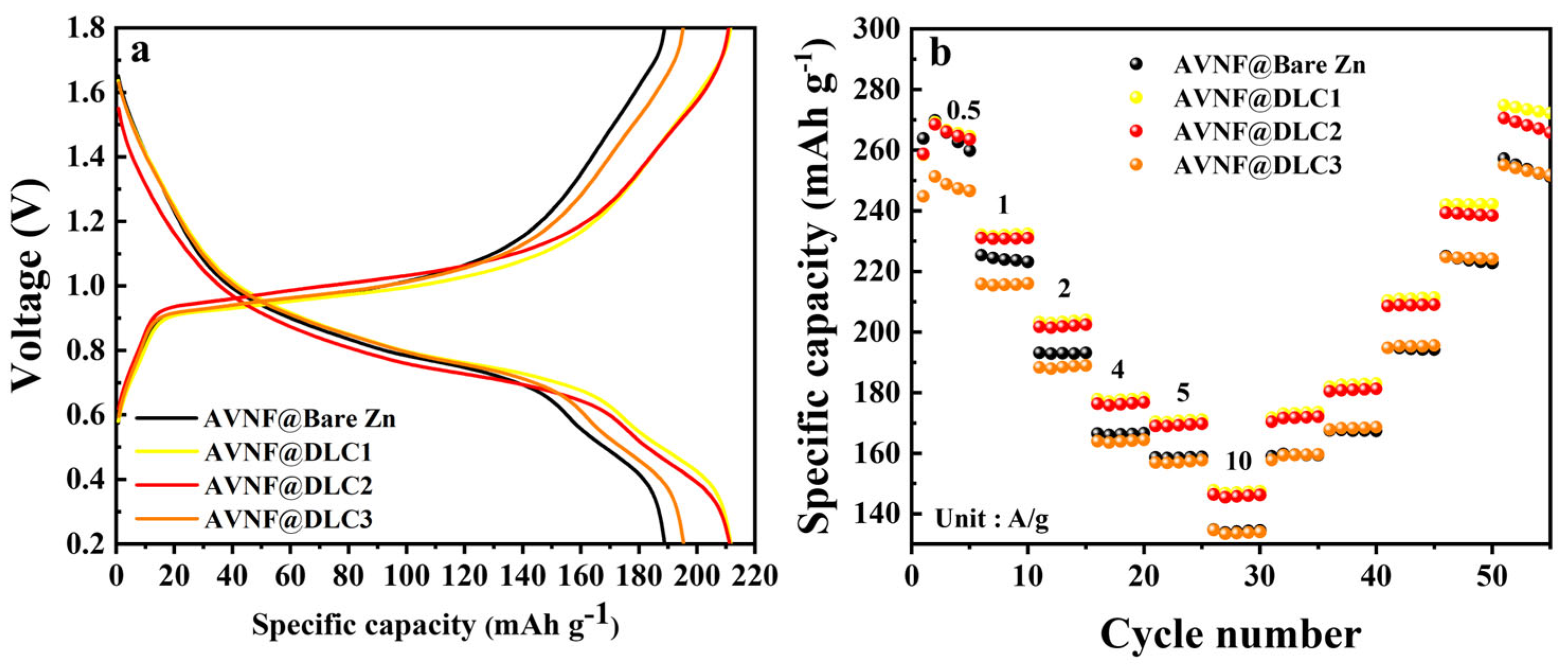
The cycling performance of the aqueous zinc battery was significantly influenced by the thickness of the DLC coating on the zinc anode. As shown in
Figure 8, when the coating thickness increased from DLC1 to DLC2, the cycle stability improved, indicating that the DLC layer effectively enhanced the durability of the electrode. However, when the DLC thickness increased further from DLC2 to DLC3, the cycling performance deteriorated. This decline can be explained by the excessive thickness of the DLC layer hindering ion transport between the electrolyte and the zinc anode, leading to increased internal resistance, confirmed by EIS analysis in
Figure 7. The gravimetric charge–discharge and rate capability of the full cell with DLC-coated Zn anode and AVNF are also documented in
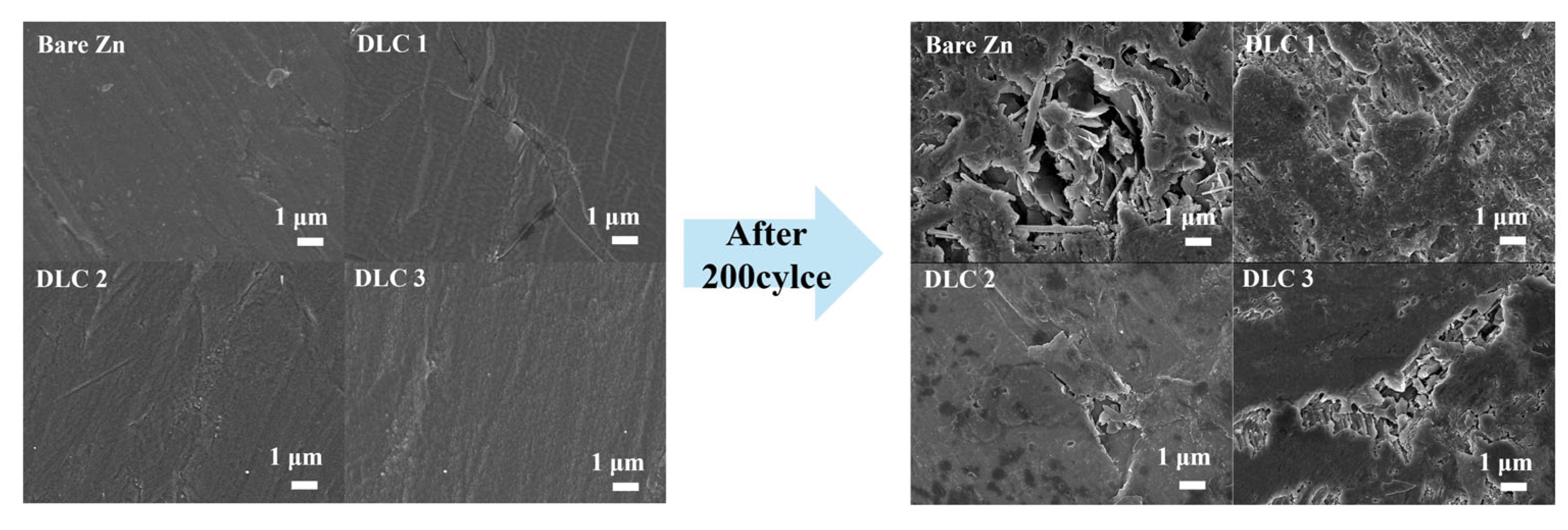
Figure 9. This result was also confirmed by the surface morphology of the DLC-coated Zn anodes and comparatively lower internal resistance after the cycling test in
Figure 10 and
Figure 7b, respectively, which indicates the improved interfacial stability and suppressed dendrite formation, ultimately leading to enhanced electrochemical performance of the full cell.
Combined with the results of Raman analysis in
Figure 5, DLC2 indicates an optimal balance between structural order and sp
3-rich cross-linked domains but also delivered the most stable electrochemical performance in both symmetrical-cell and full-cell configurations. While DLC1 showed the lowest surface roughness and DLC3 presented the highest sp
3 content, the superior cycling stability and interfacial reversibility observed in DLC2 suggest that neither extremely smooth surfaces nor maximized structural ordering alone can ensure optimal anode protection. Instead, the synergistic combination of sufficient film density, moderate surface texture, and balanced carbon hybridization in DLC2 enables uniform Zn deposition, suppresses parasitic reactions, and maintains interfacial integrity during extended cycling. This result highlights the importance of fine-tuning both the thickness and structural characteristics of protective layers to achieve AZIBs with high electrochemical performance. Also, this result suggests that surface roughness alone is not the decisive factor in determining interfacial stability. Rather, the improved performance of DLC2 can be attributed to its balanced structural and electrochemical characteristics. The intermediate thickness of DLC2 can provide sufficient physical shielding to prevent direct contact between the Zn anode and electrolyte. In addition to that, it inhibits hydrogen evolution, while maintaining adequate ionic accessibility for uniform Zn
2+ deposition. In contrast, the thinner DLC layer, although smooth, may be too fragile or permeable to maintain long-term interfacial integrity under repeated cycling conditions [
16]. These results collectively demonstrate that optimal interfacial engineering of Zn anodes such as DLC coating on Zn anodes significantly enhances both mechanical robustness and ionic transport compatibility. Consequently, the proposed strategy yields superior electrochemical performance, with lower voltage hysteresis and extended cycling stability, compared to previously reported approaches, documented in
Table 3 [
7,
17,
34].


