Article

Binder-Free Fe-N-C-O Bifunctional Electrocatalyst in Nickel Foam for Aqueous Zinc–Air Batteries

Instituto de Cerámica y Vidrio, Consejo Superior de Investigaciones Científicas (CSIC), Kelsen 5, 28049 Madrid, Spain
*
Authors to whom correspondence should be addressed.
Batteries 2025, 11(4), 159; https://doi.org/10.3390/batteries11040159
Submission received: 12 March 2025 / Revised: 3 April 2025 / Accepted: 11 April 2025 / Published: 17 April 2025

Abstract

:
The development of efficient, sustainable, and cost-effective catalysts is crucial for energy storage technologies, such as zinc–air batteries (ZABs). These batteries require bifunctional catalysts capable of efficiently and selectively catalyzing oxygen redox reactions. However, the high cost and low selectivity of conventional catalysts hinder the large-scale integration of ZABs into the electric grid. This study presents binder-free Fe-based bifunctional electrocatalysts synthesized via a sol–gel method, followed by thermal treatment under ammonia flow. Supported on nickel foam, the catalyst exhibits enhanced activity for both the oxygen reduction reaction (ORR) and oxygen evolution reaction (OER), essential for ZAB operation. This work addresses two critical challenges in the development of ZABs: first, the replacement of costly cobalt or platinum-group-metal (PGM)-based catalysts with an efficient alternative; second, the achievement of prolonged battery performance under real conditions without passivation. Structural analysis confirms the integration of iron nitrides, oxides, and carbon, resulting in high conductivity and catalytic stability without relying on precious or cobalt-based metals. Electrochemical tests reveal that the catalyst calcined at 800 °C delivers superior performance, achieving a four-electron ORR mechanism and prolonged operational life compared to its 900 °C counterpart. Both catalysts outperform conventional Pt/C-RuO2 systems in stability and selective bifunctionality, offering a more sustainable and cost-effective alternative. The innovative combination of nitrogen, carbon, and iron compounds overcomes limitations associated with traditional materials, paving the way for scalable, high-performance applications in renewable energy storage. This work underscores the potential of transition metal-based catalysts in advancing the commercial viability of ZABs.

1. Introduction

Developing efficient, cost-effective, and sustainable electrochemical energy storage systems is a topic of special interest due to the high cost of conventional catalysts, economically and environmentally, the low energy density of Li-ion batteries, and the acceleration of the incorporation of weather-dependent energy sources into the electrical grid [1,2]. Metal–air batteries, especially Zn–air secondary batteries (ZABs), have been presented as a promising alternative to conventional Li-ion batteries. ZABs present three times the energy densities of Li-ion batteries, allowing safe aqueous electrolytes and avoiding using highly flammable electrolytes and electrodes that can accelerate combustion by thermal decomposition, such as LiCoO2 [3]. However, the lack of viable air electrodes with improved kinetics for both the oxygen evolution reaction (OER) and oxygen reduction reaction (ORR) remains the main limiting factor for the implementation of ZABs as a viable substitute for conventional batteries [4]. In addition, the lack of a stable counter-electrode limits the operational life of the ZAB, reducing the operational use of these electrodes to only a primary ZAB [2]. The economic cost and scarcity of PGM and Co-based catalysts capable of performing the role of air electrodes remain drawbacks that need to be resolved. This situation marks the need to develop efficient commercial catalysts with a prolonged life cycle for air electrodes [5].
Therefore, research groups have pursued the search for low-content or PGM-free air electrodes. Various techniques for obtaining metal-based catalysts have been proposed in the last few decades [6]. Doping a small quantity of noble metals on the surface of carbonous materials has proven an efficient method to achieve a bifunctional catalyst. However, this method requires costly PGM and strategic materials and generally requires carbonous support material, which tends to form dendrites and other passivation structures [7]. The resulting catalysts are prone to limited operational life of this catalyst and structural problems [8]. Another alternative is the use of Co-based materials due to the extensive catalytic properties of this metal. Co-based catalysts tend to be used within metal-organic frameworks (MOFs) to improve the structural stability and electrical conductivity, facilitate the incorporation of complementary catalysts, and improve the activity of this catalyst [9]. These compounds allow Co-based, non-noble metal catalyst production with selective catalytic performance for ORR and OER and improved operational life of the catalyst [10], but Co-based compounds still tend towards long-term degradation of the compounds of the air electrode, a considerable cost, and present undesired secondary reactions, like the hydrogen evolution reaction (HER), which can promote the degradation of the electrochemical system [11].
An alternative of special interest is the use of inexpensive transition-metal-based catalysts (M-N-C) with catalytic activity for both ORR and OER; these catalysts are usually oriented for use in aqueous alkaline electrolytes due to their improved catalytic activity and stability in this medium [12]. Transition metal oxides and hydroxides exhibit promising electrocatalytic properties that allow the substitution of the PGM, such as Pt for the ORR and RuO2 for the OER, or Co catalysts [13]. However, transition metal oxides and hydroxides have poor electrical conductivity, requiring complementary compounds or a conductive substrate, commonly graphite or carbon nanotubes [14]. Another alternative is using a minimized particle size catalyst, increasing the active surface area. The reduction in the catalytic particle size implies that previously insulated metallic particles can participate in redox reactions, improving the catalytic properties of the transition metal oxides [15]. Some transition metals of special interest as catalysts for ZAB are Co [11], Fe [16], Mn [17], and Ti [18]. While Fe oxide catalysts have been reported, they are deployed in association with Co oxides to provide significant electrocatalytic properties. These catalysts are commonly supported on a carbon-based high-conductivity substrate, maintaining the shortcomings of using carbon-based substrates and the problems of using strategic materials, like Co [19].
In the present work, Fe-based bifunctional catalysts have been synthesized by the sol–gel method from iron chloride, urea, and surfactants, and analyzed as bifunctional catalysts supported on Ni foam without binders for air electrodes in an aqueous ZAB. The electrochemical analysis has shown an improved operational life while remaining structural and electrochemically stable. The combination of N, C, and O into the catalyst structure allows excellent electrochemical performance.

2. Materials and Methods

2.1. Sol–Gel Synthesis

The Fe-based solution was synthesized using the sol–gel method with surfactants and urea, as illustrated in Figure 1. The solutions were prepared by a two-stage process, requiring the preparation of two separate solutions simultaneously. Solution (a) was obtained by adding FeCl3·6H2O (Merck, Darmstadt, Germany, 97%) to a closed flask under a nitrogen (N2) atmosphere. Anhydrous methanol (Aldrich, St. Gallen, Switzerland, 99.8%) was then added, and the mixture was stirred until the metal salt was completely dissolved, which took about 5 min. Once the solution was clear and free of precipitates, urea (Aldrich, St. Gallen, Switzerland, 99.5–100.5%) was added, and the mixture was kept under constant stirring for 3 h. Solution (b) was prepared by mixing Resol, a phenolic resin surfactant previously synthesized in-house [20], with Triton X-100 (Aldrich, St. Gallen, Switzerland, 98%), a commercial surfactant, and tetrahydrofuran, THF (Merck, Darmstadt, Germany, 99.9%). This mixture was stirred for 3 h under a nitrogen (N2) atmosphere. After both solutions were prepared, they were mixed and stirred together for 12 h.
The molar ratios of the compounds used for the synthesis are 1 FeCl3-6H2O/37 methanol/8 urea/61 THF/0.23 Triton X-100. Due to Resol’s variable and undetermined molecular weight, a 1:1 mass ratio between Resol and Triton X-100 was selected. The resulting solution was dried for 12 h in a stove, with the gas exhaust at 40 °C, producing a gel.
This gel was used to (1) obtain the catalyst supported on Ni foam, which was required to perform the electrochemical analysis of the catalyst; and (2) obtain the catalyst powder, which was used for the structural analysis and electrochemical characterization in rotating disk electrode (RDE) tests. Catalysts supported on Ni foam were obtained by pressing the gel produced, after drying at 40 °C, into an 18 mm diameter circular Ni foam (Recemat BV, Dodewaard, Netherlands) without using binders and additional electrically conductive additives.

2.2. Thermal Treatments

As shown in Figure 1, two thermal treatments were used to assess the impact of the calcination process on the properties of the catalyst in both the catalyst supported in Ni foam and the catalyst powder. The first one consisted of a treatment at 220 °C in an autoclave for 6 h to improve reactivity and urea conversion [21,22]. Subsequently, the gel underwent a calcination process at either 800 °C or 900 °C for 2 h in a tubular oven with an NH3 flow of 0.5 L/min to incorporate N into the catalyst structure.

2.3. Structural and Electrochemical Characterization

Elemental analysis was performed to measure the incorporation of N and C in the synthesized catalyst using a LECO CHNS-932 (LECO Instrumentos S.L., Tres Cantos, Spain). Thermogravimetric analysis (TGA) and differential thermal analysis (DTA) were performed using a Thermobalance TGA Q500 (TA Instruments, Cerdanyola del Valles, Spain) instrument between 25 °C and 600 °C in air, using the gel after drying at 40 °C. Morphological analysis was performed using a field emission scanning electron microscope (FE-SEM) Hitachi S-4700 (Hitachi High-Tech Europe, Krefeld, Germany), operated at 20 kV. A Quanta Chrome model Monosorb instrument, (Quanta System, Milan, Italy) (Madrid, Spain) was used to measure the surface area of the powder catalyst after calcination at 800 °C and 900 °C via N2 adsorption/desorption utilizing the Brunauer–Emmett–Teller (BET) method. Before analysis, the powder catalyst underwent a 2 h degassing process in an Ar flow at 150 °C. Crystalline phase composition analysis of the catalyst was carried out using a Bruker D8 Advance instrument (Bruker, Madrid, Spain) with CoKα radiation (λ = 0.1787897 nm), and the resulting spectra were interpreted using the software DIFRACT.EVA 6.3. Fourier transform infrared (FT-IR) analysis was conducted on a powder catalyst utilizing a Perkin Elmer Spectrum 100 (Perkinelmer, Tres Cantos, Spain) spectrometer equipped with the PIKE GladiATR accessory. Raman analysis was performed using a WITec/ALPHA 300AR (Oxford Instruments Group, Abingdon, UK) instrument with a 0.3 mW power laser. The catalysts’ surface structures and chemistry properties were analyzed via an X-ray photoelectron spectroscopy (XPS) using a FlexPS-ARPES-E K-Alpha X-ray system (SPECSGroup, Barcelona, Spain).
A multichannel Potentiostat (VMP3, Biologic) (BioLogic Science Instruments, Madrid, Spain) was used to evaluate the catalysts’ electrochemical properties. An RDE 3-A (Als) rotating disk electrode was used to measure the number of electrons involved in the ORR and also to evaluate OER performance. A carbon rod electrode was used as a counter electrode (CE), while a Hg/HgO electrode was used as reference electrode (RE). For the working electrode, 4 aliquots of 2 μL of catalytic ink were deposited onto a carbon 5 mm diameter RDE. The ink was obtained by mixing 5 mg of the catalyst with 30 μL of 5 wt% Nafion solution (Sigma-Aldrich, St. Gallen, Switzerland) and 1 mL of isopropanol (Merck, Darmstadt, Germany, 99%) after ultrasonication for 45 min. A 1 M KOH aqueous solution was used as the electrolyte, which was consistently supplied throughout the electrochemical analyses with a constant flow of 50 SCCM of O2. To determine the electron transfer number (n) per oxygen molecule in the ORR process, LSV polarization curves with different rotation speeds (400–2200 rpm) were measured. The correlation between the disk current and the kinetic current density was obtained from the Koutecký–Levich equation, where j is the measured current density, jk is the kinetic current, and jd is the limiting diffusion current:
1/j = 1/jk + 1/jd
The limiting diffusion current was obtained from the following equation:
Jd = 0.62nFACoDo2/3ν−1/6ω1/2 = 1/2
where jk, jd, Do, ν, F, Co, and n correspond to the kinetic current, diffusion current, diffusion coefficient of oxygen in KOH, KOH solution viscosity, Faraday constant (96,500 C), KOH bulk concentration, and the number of electrons transferred in the process, respectively. B is the slope of the Koutecký–Levich plot, and ω is the rotational speed. The slope of the Koutecký–Levich plot current density (J−1) as a function of the inverse square root (1/ω1/2) of rotational speed at different potentials gives B, from which the number of electrons transferred in the ORR process (n) can be determined. The resulting number of electrons was adjusted to 2 or 4 electrons [23].
Two different setups were employed to evaluate the battery performance of the catalyst at room temperature: a membrane-less three-electrode beaker cell and a two-electrode cell with a commercial alkaline membrane AHA (Astom, Ujitawara, Japan) between the anode compartment and air electrode, as depicted in Figure 2.
For the three-electrode setup, the working electrode (WE), or air electrode, consisted of an 18 mm diameter Ni foam with the Fe-based catalyst supported. The counter electrode (CE) was prepared by applying 2000 kp of pressure to Zn powder (Aldrich) until a cylindrical Zn pellet with a radius of 0.9 cm and a thickness of 0.3 cm was obtained, while a commercial Hg/HgO electrode served as the reference electrode (RE). A 1 M KOH solution was used as the aqueous electrolyte. In this system, the 3 electrodes (WE, CE, and RE) were in direct contact with the electrolyte without a membrane between the electrodes. Oxygen was supplied to the aqueous electrolyte at a constant flow of 50 sccm.
In the two-electrode cell, the CE was submerged in the electrolyte, also functioning as the RE. The WE was composed of the Ni foam supporting the Fe-based catalyst. The WE was kept in direct contact with the membrane, which acted as a separator between the electrodes, preventing the Zn ions from transiting to the air electrode. Mesoporous C paper was attached to the outmost face of the Ni foam to reduce electrolyte leakage outside the cell.
Cyclic voltammetry (CV) measurements were conducted using the three-electrode cell within the voltage range of −0.3 to 0.8 V vs. Hg/HgO and a scan rate of 50 mV/min. Galvanostatic charge–discharge tests were performed with a current intensity of 1 mA over the voltage range of −0.3 to 1.1 V vs. Hg/HgO. Equivalent potentials were used for the two-electrode cell that uses the Zn metal pellet as reference. As a reference for the catalytic properties of the synthesized catalyst, conventional Pt/C (40%) and Pt/C (20%)–RuO2 working electrodes were analyzed as a benchmark of the catalyst’s performance.

3. Results and Discussion

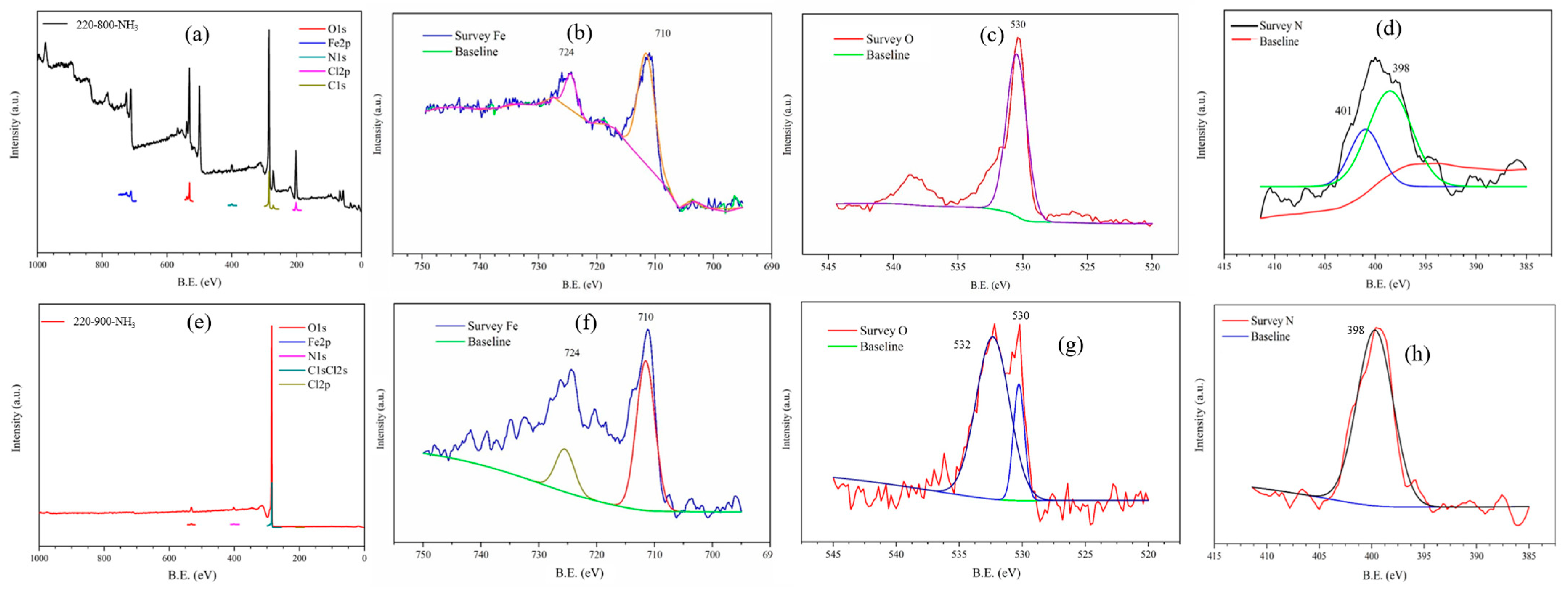
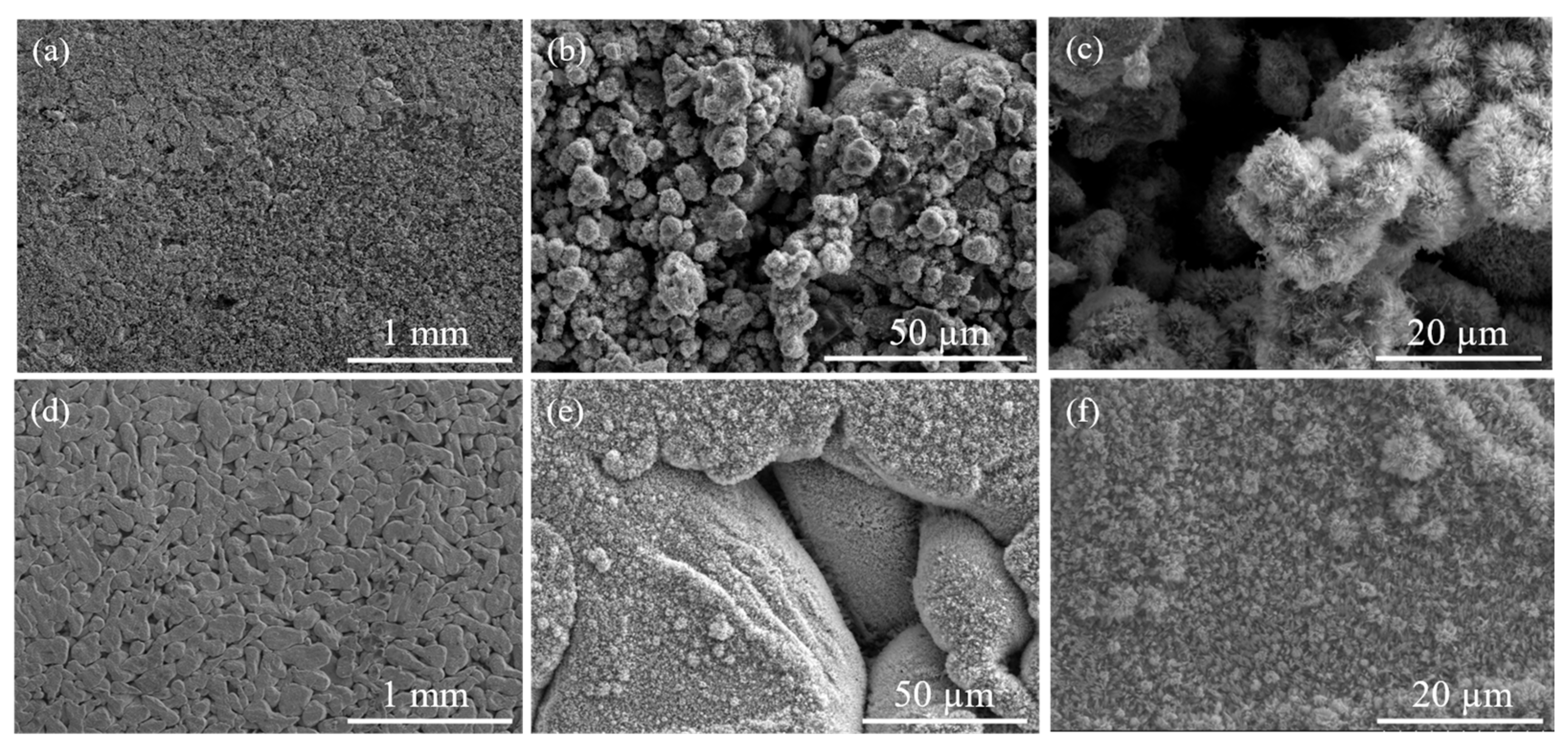
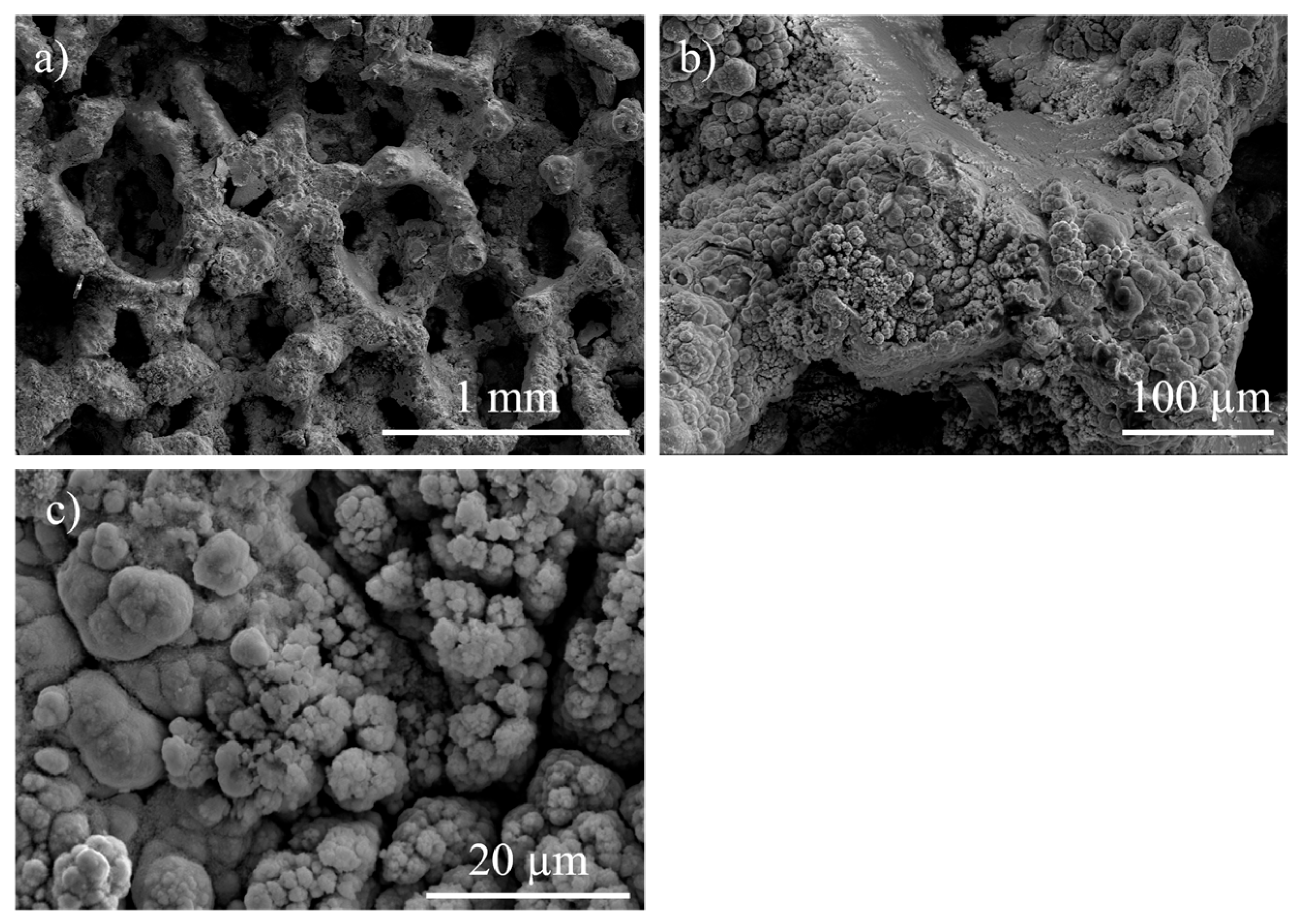
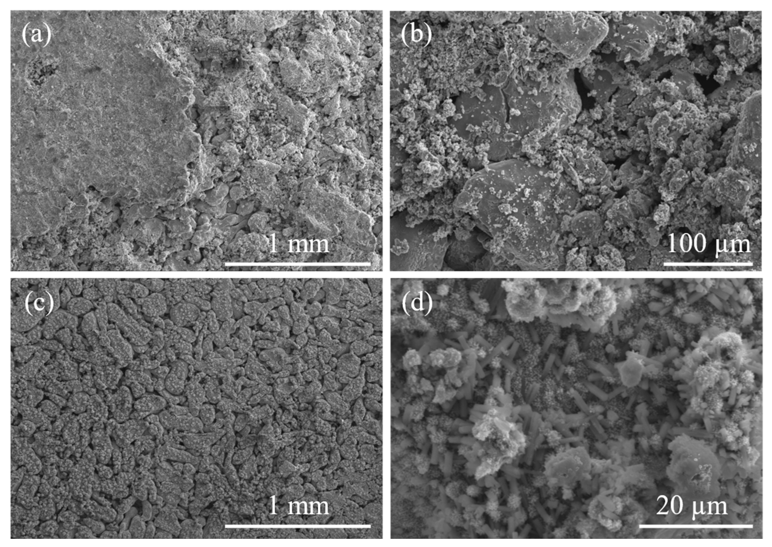
3.1. Structural and Chemical Results

All the samples were named according to the gel drying and calcination temperatures, so the catalyst gel dried at 220 °C and calcinated at 800 °C has been denominated 220–800. After gel drying and calcination, all the catalysts exhibited a uniformly dark black appearance, with no other significant coloration observed.
Table 1 shows the surface area and weight percentages of the N and C of the catalyst after calcination. This analysis proves that the initial gel drying at 220 °C and calcination at 800 and 900 °C allowed the incorporation of N and C into the catalyst structure. These results show a significant amount of carbon in both samples because the high-temperature thermal treatment was performed in NH3 flow. Powder catalysts 220–800 and 220–900 present similar surface area results of 90.7 and 92.4 m2/g, respectively. The gel solution dried at 40 °C was analyzed by thermogravimetry analysis (TGA) and differential thermal analysis (DTA) in air, as shown in Figure 3.
The curves were analyzed by dividing them into four distinct regions based on the temperature-dependent evolution of weight loss. Region I, from room temperature to 150 °C, exhibits a total weight loss of 10.1% of the initial weight, attributed to the desorption of adsorbed water and residual solvents from the sol–gel synthesis process. Several endothermic peaks are associated with these processes. Region II, ranging from 150 °C to 265 °C, features an endothermic peak at 240 °C. This peak corresponds to the decomposition of molten urea, resulting in the generation of NH3 and HNCO, with a subsequent weight loss of 30.5% [24]. Region III, from 265 to 515 °C, encompasses four exothermic peaks. The first peak, observed at 300 °C, indicates an exothermic reaction in the gas phase between the released HNCO and water vapor, along with other solvents, resulting in the generation of NH3 and CO2 [25]. The subsequent peaks at 350, 450, and 505 °C are attributed to the removal of surfactants Triton X-100 and Resol, respectively, contributing to a total weight loss of 90%. Finally, no significant weight loss is observed in Region IV beyond 515 °C.
Figure 4 presents the SEM images of the air electrode after calcination at 800 °C (Figure 4a,b) and 900 °C (Figure 4c,d). Figure 4a,c shows that after calcination, the catalysts remain in contact with the Ni foam and partially cover the internal porosity, leaving interconnected void space to allow the penetration of the liquid electrolyte. Figure 4b,d confirms that the catalyst has coated the Ni foam, with porosity and cracks that can improve the contact with the electrolyte. EDS confirms the incorporation of N into the Fe-based catalyst structure.
Figure 5a presents the X-ray diffractograms after calcination at 800 °C and 900 °C, confirming that these thermal treatments in NH3 flow produce the catalysts’ nitridation. Both catalysts have similar diffractograms with crystalline phases of iron nitride (Fe2N) (PDF-06-0656), (Fe4.4N) (PDF 03-0995), and graphite (C) (PDF 03-0401). Sample 220–900 shows a higher crystallinity due to the increase in temperature. A wide peak between 15 and 35 ° can be observed, which indicates carbon compounds (C) (PDF 03-0401). Figure 5b shows the FT-IR analysis of the Fe-based powders after calcination in ammonia. Both catalysts exhibit wide bands between 520 and 440 cm−1 corresponding to metal-O stretching bonds [25]. The 220–800 and 220–900 catalysts show three main bands at 1730, 1380, and 1220 cm−1. The band at 1730 cm−1 can be attributed to the stretching vibration of imide groups [26], the band at 1380 cm−1 hints at the incorporation of nitrogen into the structure with a stretching band linked to C-N o amide bonds [27], and the band at 1220 cm−1 is related to C-N stretching bonds [28,29]. FT-IR analysis confirms the incorporation of N and C into the catalyst powder and the presence of Fe-O bands [28,29].
Both iron-based catalysts display similar Raman spectra with similar band distribution and different intensities (Figure 5c). Superficial and a deep Raman analyses were performed to analyze the chemical composition of the surface and bulk catalyst. C-linked bands are predominant on the catalyst’s surface, and iron oxides and nitrides have been detected beyond the surface. Bands corresponding to D band sp3-type disordered carbon and G band sp2-type ordered graphitic carbon are observed at 1595 cm−1 and 1310 cm−1, respectively. The analysis of the C-bands indicates that the carbon compounds in the catalyst treated at 900 °C exhibit a higher degree of ordering compared to those treated at 800 °C. Below 1000 cm−1, both catalysts display bands at 670, 570, and 300 cm−1 related to magnetite (Fe3O4) [27]. The weak band at 540 cm−1 has been attributed to iron nitrides (Fe3N1+x). The signal intensity of these bands is linked to the laser’s decomposition of these nitrides in an oxygen atmosphere [30]. The band at 370 cm−1 detected in 220–900-deep corresponds to ferrihydrite (Fe2O3·9H2O) [31]. The Raman result validates the previous XRD and FT-IR results, confirming the presence of amorphous iron oxides and the incorporation of C and N into the catalyst structure.
The catalytic powders were characterized by X-ray photoelectron spectroscopy (XPS) (Figure 6). The survey XPS spectra of both catalysts present Fe, C, N, and O. Cl was only detected in 220–800. The peaks at 724 eV and 710 eV are associated with Fe2p1/2, while the satellite peak at 719 eV has been attributed to the binding energy of Fe2p3/2. These peaks have been detected in both catalysts and correspond to iron (III) [32]. The O1s peak at 530 eV shows that there are O2− elements linked to metallic elements. Catalyst 220–900 presented a second peak at 532 eV linked to the formation of iron carbonates on the surface of the catalyst, associated with the presence of carbon detected by XPS [33]. The N1s peak at 398 eV confirms the nitridation of both catalysts, and the peak at 410 eV indicates the formation of C-NHx groups [34]. The C1s peak at 285 eV correlates with C-C bonds, which are more intense in the catalyst 220–900 and are linked to the prominent presence of C previously detected in the elemental analysis [35]. Finally, catalyst 220–800 presents a Cl1s peak at 201 eV, indicative of unconsumed iron precursor.

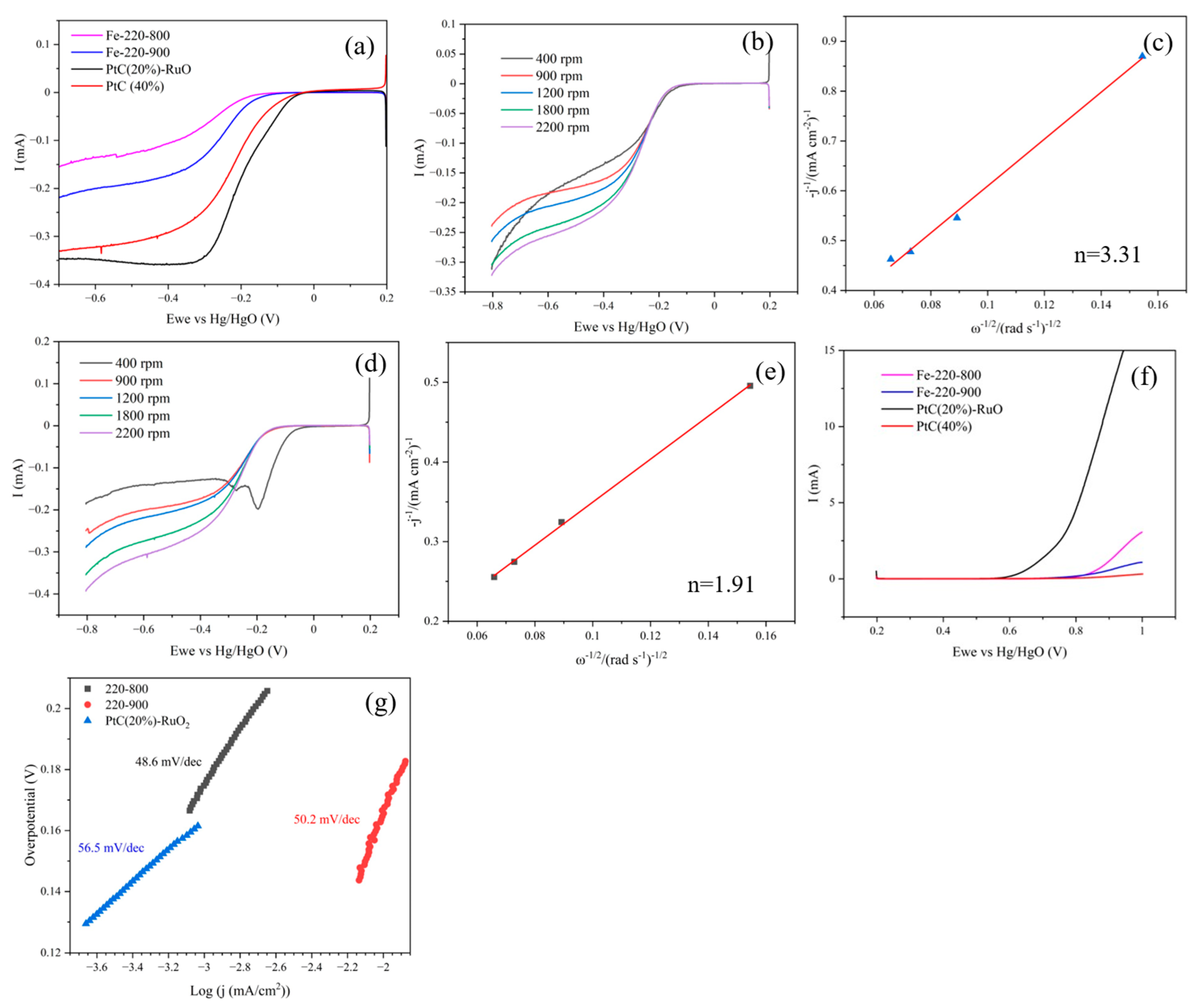
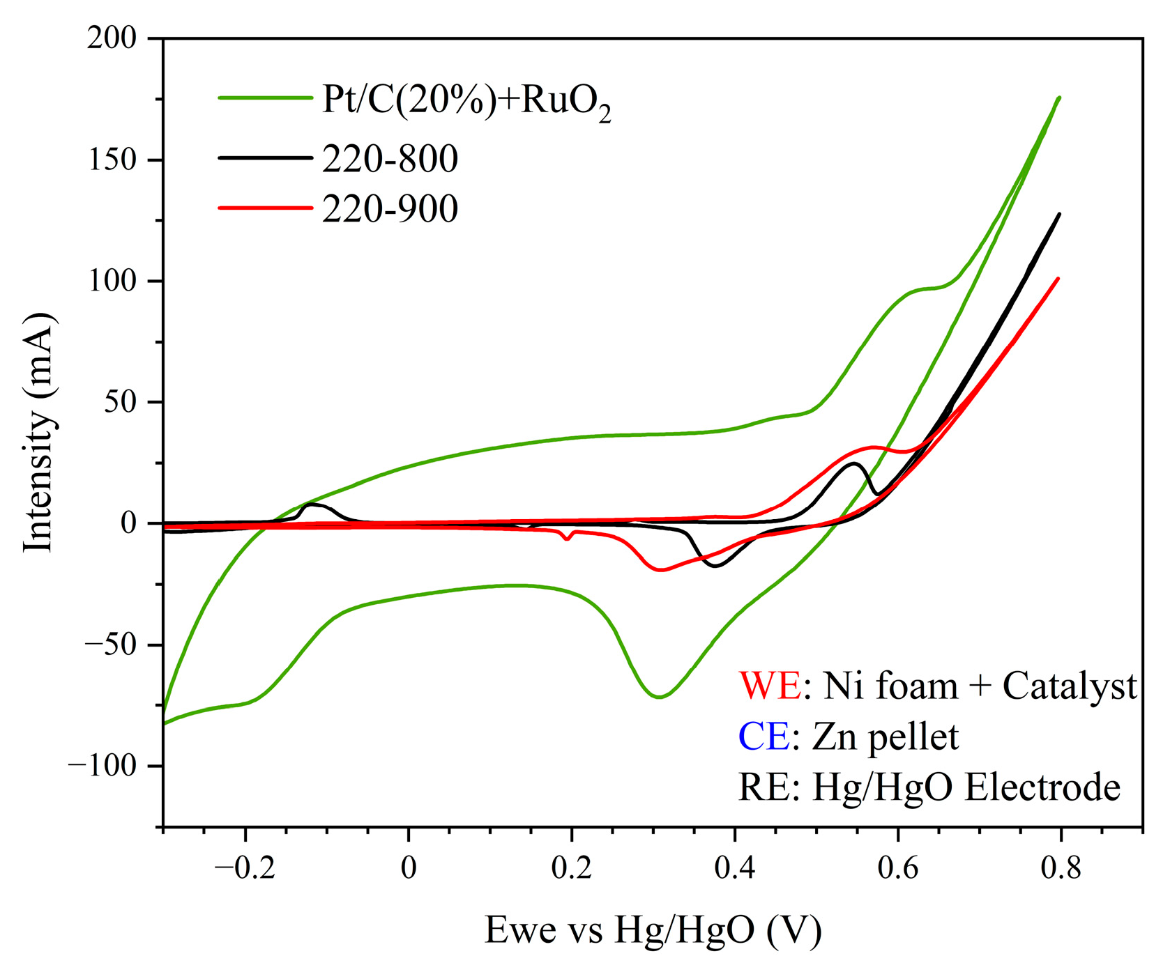
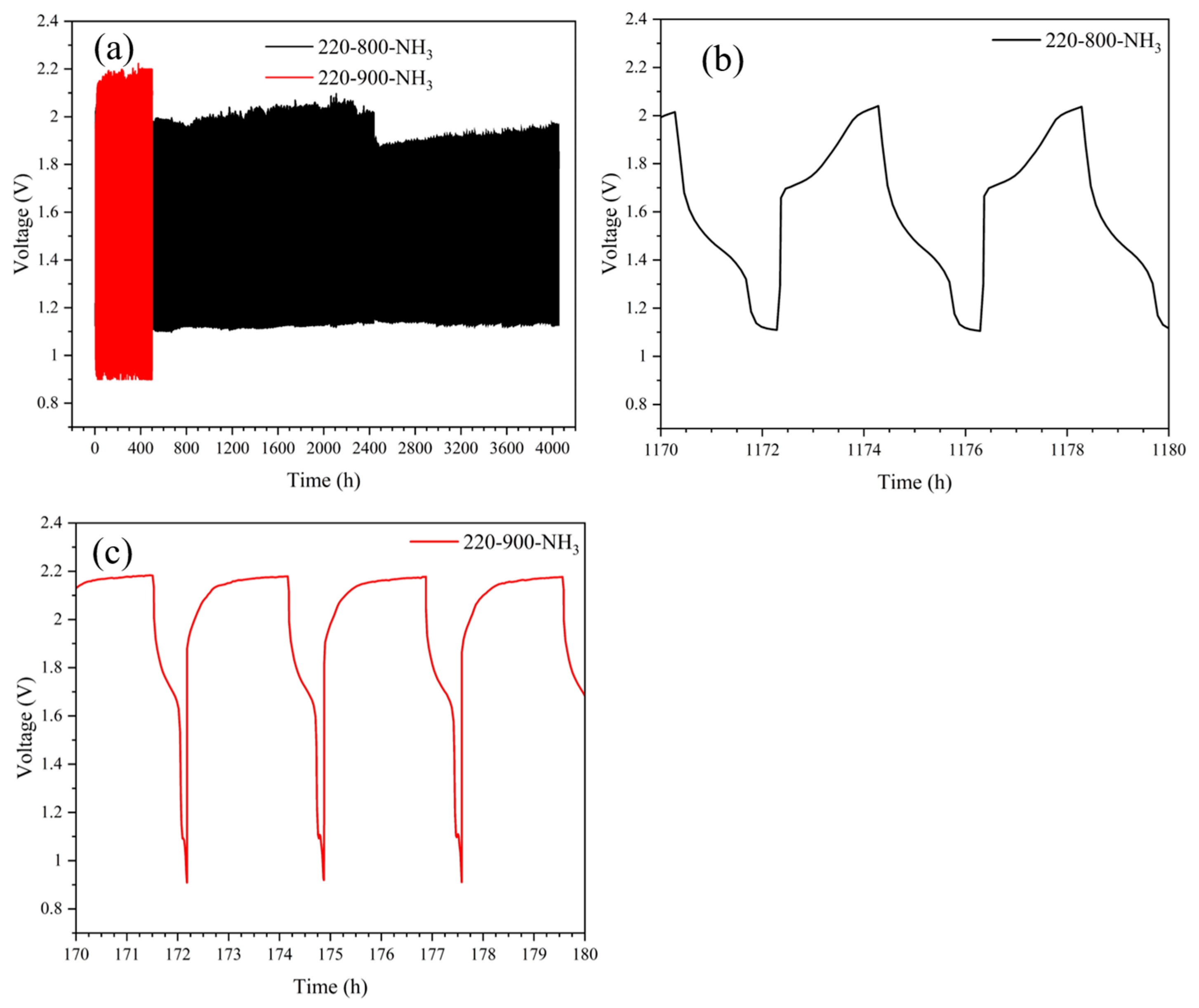
3.2. Electrochemical and “Post-Mortem” Results

Figure 7 presents the iron-based catalysts after calcination at 800 and 900 °C in ammonia and Pt-based catalyst analysis of ORR and OER by RDE. Figure 7a shows that catalysts 220–800 and 220–900 present lower signal intensity than conventional Pt-based catalysts, as expected, due to the lack of selectivity and high conductivity of Pt-derived catalysts. Figure 7b,c indicates that catalyst 220–800 performed the ORR with a unique transfer of four electrons (n = 3.31 electrons), while 220–900 (Figure 7d) displays less current intensity than the catalysts based on Pt. Figure 7e indicates that 220–900 catalyzes two reactions with two transfer electrons (n = 1.91 electrons). The current intensity values for OER observed in Figure 7f indicate that both catalysts present better bifunctional performance than Pt/C (40%). The higher current intensity observed for the Pt/C (20%)-RuO2 catalyst corresponds to an improved performance because of the presence of ruthenium. Figure 7g shows that both catalysts exhibit similar Tafel slopes compared to conventional Pt/C (20%)-RuO2, confirming their highly efficient cathode catalytic performance for ORR. The obtained catalysts, with a Tafel slope of 50 mV/dec, demonstrate good electrode kinetics and a reduced overpotential.
Cyclic voltammetry (CV) analysis was performed on the Ni foam-supported catalysts treated at 800 °C and 900 °C, and Pt/C (20%)-RuO2 (Figure 8) in the three-electrode cell. Both Fe-based catalysts exhibit two peaks, one cathodic and one anodic, confirming their catalytic functionality for ORR and OER. The 220–800 catalyst displays two anodic peaks and one cathodic peak. The peak at −0.12 V signals the oxidation and formation of the Ni complex on the surface of the Ni foam in the initial cycles of the CV [36]. The cathodic peak at 0.4 V and the anodic peak at 0.55 V show that the catalyst displays bifunctional performance for ORR and OER, respectively. The 220–900 catalyst also presents catalytic performance for OER and ORR, with a cathodic peak at 0.3 V, and an anodic peak at 0.57 V, assigned to ORR and OER, respectively. No peak associated with the hydrogen evolution reaction (HER) is detected, proving that catalyst 220–900 is a selective catalyst for ORR and OER. The CV analysis of both Fe-based catalysts indicates lower current intensities than the Pt/C (20%)-RuO2 catalyst for both ORR and OER. However, the Pt/C (20%)-RuO2 catalyst also promotes secondary undesired reactions, like HER detected below −0.1 V vs. Hg/HgO.
The galvanostatic cycling test in the three-electrode cell was performed on the catalyst supported on Ni foam at 1 mA, with each charge and discharge cycle lasting a maximum time of 60 min to reduce the degradation of the electrode at higher potentials (Figure 9).
The test was performed between −0.3 V and 1.1 V vs. Hg/HgO. Figure 9a reveals that 220–800 maintains constant cycling for 600 h. Beyond this point, a drastic decrease in the WE potential is detected, resulting in the end of the test. This process could be attributed to the total passivation of the CE. Figure 9b,c represents 10 h segments of the galvanostatic cycling, in which only two redox processes, the ORR, between 0.6 and 0.3 V, and the OER, between 0.5 V and 0.6 V, can be observed. These results confirm that 220–800 is a bifunctional catalyst, selective for ORR and OER, that does not promote undesirable reactions, such as HER, and exhibits longer operational life than similar PGM-free catalysts or even catalysts based on Co and PGM [5]. Figure 9d–f illustrates the galvanostatic cycling of 220–900. Figure 9d shows that 220–900 can cycle 432 h without showing signals of passivation. Figure 9e shows that during the initial 320 h, the system displays two well-defined redox reactions: the OER, during the charge between 0.5 and 0.6 V, and the ORR, between 0.4 and 0.1 V, consuming the 60 min limit, without reaching the lower limit of −0.3 V at the end of the discharge cycle. Beyond the 320 h of cycling, an increase in the maximum potential reached during the charge is detected, from 0.58 V to 0.64 V, as presented in Figure 9f. This increase has been linked to a deterioration of the electrodes, reducing the catalytic performance for OER. The early degradation of the electrodes in 220–900 has been attributed to the peroxide formation in the air electrode linked to the two-electron reaction. The galvanostatic cycling test indicates that both catalysts, 220–800 and 220–900, display catalytic behavior for both ORR and OER without promoting secondary reactions; the 220–800 catalyst displays better electrochemical stability and extensive operational life. These results are in agreement with the previous CV analysis. Figure 9g indicates that the Pt/C (20%)-RuO2 catalyst shows a similar operational life in comparison with 220–900. Figure 9h indicates that this electrode shows more unstable cycling. As displayed in Figure 9i, beyond 400 h, the working electrode cycling stabilizes, presenting some catalytic performance for ORR and OER, although it is worse in comparison with the Fe-based catalyst due to the degradation of the electrolyte, as is observed in the plateau at high potential observed in Figure 9i [37]. At 469 h, the potential drops, finalizing the test due to the degradation of the system.
As presented in Figure 10, post-mortem analysis of the electrodes was performed using SEM images after the electrochemical analysis in the three-electrode cell. Figure 10a–c shows the air electrode with catalyst 220–800 after galvanostatic charge–discharge analysis at different magnifications. Figure 10a confirms that the catalyst remains connected to the Ni foam substrate after prolonged cycling, and Figure 10b,c shows a segment of the Ni foam fully covered by two different catalyst morphologies, a fractured coating on the Ni foam and a porous deposit on the Ni foam. Figure 10d–f exhibits the air electrode SEM images of catalyst 220–900 after galvanostatic charge–discharge analysis at different scales. These images also show a catalyst adhered to the Ni foam, although some degradation of the catalyst with a partial detachment can be observed in Figure 10f.
The post-mortem analysis of the counter-electrode (CE) (Figure 11) was performed to determine whether passivation layers had been developed on its surface after cycling. Figure 11a–c displays the SEM images of the CE after cycling using the catalyst 220–800 at different scales. Figure 11a,b shows a noticeable growth of particles between 5 and 10 µm on the surface of the Zn particles. Figure 11c shows that the particles generated are fully covered by filamentous structures generated during the cycling of the battery. The micrographs show open porosity that allows the electrolyte penetration and the battery cycling. On the other hand, Figure 11d shows a general view of the Zn pellet (CE) used for the electrochemical characterization of 220–900 air electrodes assembled by particles around 150 µm in length. Figure 11e,f displays the SEM images of Zn particles at higher magnifications. In this case, catalyst 220–900, the particle nucleation predominates over the particle growing, leading to an almost non-porous coating that can passivate the electrode surface, as the electrochemical results indicated.
Figure 12 shows the electrochemical results of a battery test performed in a two-electrode Zn–air battery for catalysts 220–800 and 220–900, where the air electrode is open to the atmosphere.
Figure 12a shows the galvanostatic charge–discharge test performed between 0.9 V and 2.2 V vs. Zn metal with a maximum charge and discharge time of 120 min. The results indicate that catalyst 220–900 can cycle for a period of 470 h before the system’s failure, probably because of the Zn electrode passivation, previously observed, and the ORR mechanism through a two-electrode reaction that degrades the electrode prematurely. Catalyst 220–800 offers excellent operational life beyond 2200 h, with a decrease in the cycling efficiency inferior to 0.25% in the discharge time between t = 0 h and t = 2200 h. Figure 12b displays a 10 h segment of the galvanostatic cycling of 220–800, indicating that the evolution of the redox potential is modified for two redox processes, the ORR, between 1.6 and 1.3 V, and the OER, between 1.7 V and 2.0 V, without reaching the water oxidation potential during the maximum time of charge. These results indicate that 220–800 is an efficient bifunctional catalyst that is selective for ORR and OER. These results correlate with the three-electrode test results previously presented. Figure 12c showcases a 10 h segment of the galvanostatic cycling of 220–900, showing faster charge and discharge processes than 220–800. The shorter time for the charge is because the potential reaches the maximum potential (2.2 V vs. Zn) due to the lower OER activity. The discharge process is also shorter than 220–800 because of the lower ORR activity that allows reaching the minimum potential of 0.9 V vs. Zn more quickly.
Figure 13 shows the charge and discharge profiles for different cycles. The mass of the catalyst deposited (30 mg) on nickel foam has been used as a reference to calculate the gravimetric capacity. The capacity (C) is determined using the following equation, where tc is the cycling time for charge or discharge, I is the electric current, and mc is the mass of the catalyst:
C = tc × I × mc−1
Figure 13a shows the charge and discharge profiles of the 220–800 catalyst. The results indicate that, after an initial stabilization period, the capacity profiles as a function of potential stabilize, maintaining a capacity of around 80 mAh/g, even after 600 cycles. It is worth noting that the low current intensity (1 mA) and the time limitation in the charge and discharge processes likely prevented achieving higher capacity values. On the other hand, Figure 13b shows the capacity evolution profiles as a function of electrical potential for the 220–900 catalyst, where greater degradation in capacity retention is observed as the cycle number increases. By cycle 400, only 20% of the original capacity is retained, in agreement with the previous results.
Figure 14 presents the SEM images of the surface of the 220–800 air electrode after cycling at 1 mA. Figure 14a shows an overview of the air electrode after 4100 h of cycling tests at 1 mA. The image reveals the accumulation of precipitates on the surface of the nickel foam (Figure 14b,c) but without clogging the porosity, which is crucial for maintaining a high active surface area. These precipitates are composed of ZnO and KOH (confirmed by EDS analysis), indicating that Zn ions are capable of crossing the AHA membrane and precipitating on the surface of the air electrode.
Figure 15 presents SEM images of the surface of the 220–900 air electrode after cycling at 1 mA with the two-electrode cell.
The SEM images also show precipitates covering the Ni foam but without clogging the internal porosity of the Ni foam, as in the case of the 220–800 catalyst. These images demonstrate that the worse electrochemical behavior of the 220–900 catalyst cannot be associated with more intense degradation of the air electrode. The main parameter to explain the cycling difference between both catalysts probably would be the ORR mechanism: four- and two-electron reactions for the 220–800 and 220–900 catalysts, respectively [38].
Figure 16 shows SEM images of the surface of the counter and reference electrode after charge and discharge tests at 1 mA for the 220–800 and 220–900 catalysts.
The SEM images show that the counter-electrode is covered by ZnO and KOH crystals. The higher number of precipitates in the case of the 220–800 catalyst is associated with the more prolonged cycling of this test (t ≥ 4100 h). Nevertheless, this deposit consists of crystals smaller than 20 µm, which do not clog the porosity of the counter-electrode [39].

3.3. Comparison with Previous Studies

Table 2 presents the main electrochemical properties of Fe-based catalysts for Zn–air batteries extracted from relevant recent publications. The results obtained in the present work are integrated into the table, where NA means “not available”, n is the electron transfer number, C/D means charge–discharge, CV means cyclic voltammetry, and V is V vs. SHE.
These values indicate that catalysts based on Fe present a wide disparity of catalytic performance. While an adequate catalytic performance for ORR is expected for most of these catalysts, the reduced performance for the OER is evident for most of the previously reported works. Both the developed catalysts in this work present an average improved performance compared to previous work. It is noteworthy that both catalysts have an outstanding operational life and clearly show bifunctional catalytic activity for ORR and OER in their CV and charge–discharge cycling.

4. Conclusions

A two-step synthesis has been developed to obtain a binder-less, PGM, and Co-free iron-based catalyst supported in Ni foam for Zn–air batteries. The combination of the sol–gel method and surfactants, and incorporation of N through urea into the structure allows the synthesis of bifunctional catalysts for both ORR and OER after calcination in ammonia flow. Characterization of the sample by FT-IR, Raman, XRD, and XPS confirms the development of heterogeneous catalysts formed by iron nitrides, iron oxides, and carbon that efficiently coat the Ni foam substrate material, allowing desirable electrical conductivity and active areas without the use of binders, as proven by SEM images. The electrocatalytic performance of the catalyst has been demonstrated by RDE analysis, tested in a three-electrode system at different rotation speeds. The battery tests proved that bifunctional, selective, and efficient Zn–air batteries have been assembled. Catalyst 220–800 offers a longer operational life and employs the ORR pathway of four electrons in alkaline medium, while catalyst 220–900 shows a shorter operational life attributed to a two-electron pathway. Both catalysts have demonstrated improved operational life, selectivity, and bifunctional performance than catalysts that employ carbon-based materials and Co- or PGM-based catalysts. Another significant advantage is the reduced cost of this catalyst compared with conventional ones. The case of catalyst 220–800 is of special relevance, providing an improved operational life of 4000 h, beyond the average hundreds of hours presented in most of the previous results.

Author Contributions

Conceptualization, M.A. and J.M.; methodology, J.G.-M., J.M., and M.A.; validation, M.A. and J.M.; formal analysis, J.G.-M., J.M. and M.A.; investigation, M.A. and J.M.; resources, M.A.; writing—original draft preparation, J.G.-M.; writing—review and editing, J.M. and M.A.; visualization, J.G.-M., J.M. and M.A.; supervision, J.M. and M.A.; project administration, M.A.; funding acquisition, M.A. All authors have read and agreed to the published version of the manuscript.

Funding

This research was funded by Proyectos de generación de conocimiento, Ministerio de Ciencia, Innovación y Universidades, grant number PID2023-153303OB-I00; Programas de Actividades de I+D entre grupos de investigación de la Comunidad de Madrid en Tecnologías 2024, grant number TEC-2024/ECO-31; and predoctoral contract GARJU-CAM19_PRE_ICV_002.

Data Availability Statement

The data presented in this study are available in the article.

Conflicts of Interest

The authors declare no conflicts of interest.

References

  1. Olabi, G.; Sayed, E.T.; Wilberforce, T.; Jamal, A.; Alami, A.H.; Elsaid, K.; Rahman, S.M.A.; Shah, S.K.; Abdelkareem, M.A. Metal-Air Batteries—A Review. Energies 2021, 14, 7373. [Google Scholar] [CrossRef]
  2. Christensen, J.; Albertus, P.; Sanchez-Carrera, R.S.; Lohmann, T.; Kozinsky, B.; Liedtke, R.; Ahmed, J.; Kojic, A. A Critical Review of Li/Air Batteries. J. Electrochem. Soc. 2012, 159, R1–R30. [Google Scholar] [CrossRef]
  3. Mainar, A.R.; Iruin, E.; Blázquez, J.A. High performance secondary zinc-air/silver hybrid battery. J. Energy Storage 2021, 33, 102103. [Google Scholar] [CrossRef]
  4. Chakkaravarthy, C.; Abdul Waheed, A.K.; Udupa, H.V.K. Zinc—Air alkaline batteries—A review. J. Power Sources 1981, 6, 203–228. [Google Scholar] [CrossRef]
  5. Li, Y.; Fan, X.; Liu, X.; Qu, S.; Liu, J.; Ding, J.; Han, X.; Deng, Y.; Hu, W.; Zhong, C. Long-battery-life flexible zinc–air battery with near-neutral polymer electrolyte and nanoporous integrated air electrode. J. Mater. Chem. A 2019, 7, 25449–25457. [Google Scholar] [CrossRef]
  6. Pan, J.; Xu, Y.Y.; Yang, H.; Dong, Z.; Liu, H.; Xia, B.Y. Advanced Architectures and Relatives of Air Electrodes in Zn–Air Batteries. Adv. Sci. 2018, 5, 1700691. [Google Scholar] [CrossRef] [PubMed]
  7. Moradi, Z.; Heydarinasab, A.; Pajoum Shariati, F. First-principle study of doping effects (Ti, Cu, and Zn) on electrochemical performance of Li2MnO3 cathode materials for lithium-ion batteries. Int. J. Quantum Chem. 2020, 120, e26458. [Google Scholar] [CrossRef]
  8. Wu, M.; Zhang, G.; Hu, Y.; Wang, J.; Sun, T.; Regier, T.; Qiao, J.; Sun, S. Graphitic-shell encapsulated FeNi alloy/nitride nanocrystals on biomass-derived N-doped carbon as an efficient electrocatalyst for rechargeable Zn-air battery. ChemSusChem 2021, 3, 176–187. [Google Scholar] [CrossRef]
  9. Vaitsis, C.; Mechili, M.; Argirusis, N.; Pandis, P.K.; Sourkouni, G.; Argirusis, C. MOF nanomaterials for battery cathodes. In Metal-Organic Framework-Based Nanomaterials for Energy Conversion and Storage; Elsevier Science: Amsterdam, The Netherlands, 2022; pp. 207–226. [Google Scholar] [CrossRef]
  10. Zhang, W.; Cui, L.; Liu, J. Recent advances in cobalt-based electrocatalysts for hydrogen and oxygen evolution reactions. J. Alloys Compd. 2020, 821, 153542. [Google Scholar] [CrossRef]
  11. Nguyen, L.N.; Thuy, U.T.; Truong, Q.D.; Honma, I.; Nguyen, Q.L.; Tran, P.D. Electrodeposited Amorphous Tungsten-doped Cobalt Oxide as an Efficient Catalyst for the Oxygen Evolution Reaction. Adv. Synth. Catal. 2018, 13, 1530–1534. [Google Scholar] [CrossRef]
  12. Jung, K.-N.; Hwang, S.M.; Park, M.-S.; Kim, K.J.; Kim, J.-G.; Dou, S.X.; Kim, J.H.; Lee, J.-W. One-dimensional manganese-cobalt oxide nanofibres as bi-functional cathode catalysts for rechargeable metal-air batteries. Sci. Rep. 2015, 5, 7665. [Google Scholar] [CrossRef] [PubMed]
  13. Hong, F.; Yue, B.; Hirao, N.; Liu, Z.; Chen, B. Significant improvement in Mn2O3 transition metal oxide electrical conductivity via high pressure. Sci. Rep. 2017, 7, 44078. [Google Scholar] [CrossRef]
  14. Wang, Y.J.; Fang, B.; Zhang, D.; Li, A.; Wilkinson, D.P.; Ignaszak, A.; Zhang, L.; Zhang, J. A Review of Carbon-Composited Materials as Air-Electrode Bifunctional Electrocatalysts for Metal–Air Batteries. Electrochem. Energy Rev. 2018, 1, 1–34. [Google Scholar] [CrossRef]
  15. Yang, Z.K.; Lin, L.; Xu, A.W. 2D Nanoporous Fe−N/C Nanosheets as Highly Efficient Non-Platinum Electrocatalysts for Oxygen Reduction Reaction in Zn-Air Battery. Small 2016, 12, 5013–5020. [Google Scholar] [CrossRef]
  16. Liu, X.; Xiao, Z.; Ren, J.; Wang, F.; Wei, C.; Xing, Q.; Yan, W.; Li, X.; Chen, Y. A facile iron-sulfur double-doping strategy to prepare high performance FeNx/S-NC electrocatalyst for oxygen reduction reaction in zinc-air battery. Appl. Surf. Sci. 2021, 573, 152255. [Google Scholar] [CrossRef]
  17. Ranjbar, M.; Taher, M.A.; Sam, A. Facile hydrothermal synthesis of manganese-metal organic framework nanostructures in the presence of various organic ligands for SO2 and CO2 gas adsorption. J. Porous Mater. 2016, 23, 375–380. [Google Scholar] [CrossRef]
  18. González-Morales, J.; Aparicio, M.; Rosero-Navarro, N.C.; Zanotto, F.M.; Franco, A.A.; Mosa, J. Electrochemical and structural properties of binder-free iron-based bifunctional catalyst for aqueous Zinc-Oxygen batteries. Open Ceramics. 2024, 100667. [Google Scholar] [CrossRef]
  19. Kaur Muuli, R.; Kumar, R.; Mooste, M.; Gudkova, V.; Treshchalov, A.; Piirsoo, H.-M.; Kikas, A.; Aruväli, J.; Kisand, V.; Tamm, A.; et al. Iron, cobalt, and nickel phthalocyanine tri-doped electrospun carbon nanofibre-based catalyst for rechargeable zinc–air battery air electrode. Materials 2023, 16, 4626. [Google Scholar] [CrossRef]
  20. Xu, J.; Brodu, N.; Mignot, M.; Youssef, B.; Taouk, B. Synthesis and characterization of phenolic resins based on pyrolysis bio-oil separated by fractional condensation and water extraction. Bioresour. Technol. Rep. 2022, 16, 106393. [Google Scholar] [CrossRef]
  21. Sun, J.F.; Wang, M.Z.; Zhao, Y.C.; Li, X.P.; Liang, B.Y. Synthesis of titanium nitride powders by reactive ball milling of titanium and urea. J. Alloys Compd. 2009, 486, 189–192. [Google Scholar] [CrossRef]
  22. Bashkova, S.; Bandosz, T.J. The effects of urea modification and heat treatment on the process of NO2 removal by wood-based activated carbon. J. Colloid Interface Sci. 2009, 336, 145–153. [Google Scholar] [CrossRef] [PubMed]
  23. Li, C.; Zheng, Q.; Xiang, Q.; Yu, L.; Chen, P.; Gao, D.; Liu, Q.; He, F.; Yu, D.; Liu, Y.; et al. Multielectron electrode reaction kinetics with RDE and RRDE: An advanced electrochemical laboratory experiment. J. Chem. Educ. 2021, 98, 3026–3031. [Google Scholar] [CrossRef]
  24. Schaber, P.M.; Colson, J.; Higgins, S.; Thielen, D.; Anspach, B.; Brauer, J. Thermal decomposition (pyrolysis) of urea in an open reaction vessel. Thermochim. Acta 2004, 419, 89–97. [Google Scholar] [CrossRef]
  25. Zhao, C.; Hu, Z.; Qiu, Z.; Liu, K. Urea-assisted combustion synthesis of porous Li1.2Ni0.13Co0.13Mn0.54O2 microspheres as high-performance lithium-ion battery cathodes. Micro Nano Lett. 2015, 10, 662–665. [Google Scholar] [CrossRef]
  26. Yang, L.; May, P.W.; Yin, L.; Smith, J.A.; Rosser, K.N. Ultra fine carbon nitride nanocrystals synthesized by laser ablation in liquid solution. J. Nanopart. Res. 2007, 9, 1181–1185. [Google Scholar] [CrossRef]
  27. Hsiao, S.H.; Yang, C.P.; Chen, C.W.; Liou, G.S. Synthesis and properties of novel poly(amide-imide)s derived from 2,4-diaminotriphenylamine and imide ring-preformed dicarboxylic acids. J. Polym. Res. 2005, 12, 289–294. [Google Scholar] [CrossRef]
  28. Dong, H.T. Synthesis and Reactivity of Non-Heme Iron-Nitrosyl Complexes That Model the Active Sites of NO Reductases. Ph.D. Thesis, University of Michigan, Ann Arbor, MI, USA, 2021. [Google Scholar] [CrossRef]
  29. Hwang, S.W.; Umar, A.; Dar, G.N.; Kim, S.H.; Badran, R.I. Synthesis and characterization of iron oxide nanoparticles for phenyl hydrazine sensor applications. Sens. Lett. 2014, 12, 97–101. [Google Scholar] [CrossRef]
  30. Hanesch, M. Raman spectroscopy of iron oxides and (oxy)hydroxides at low laser power and possible applications in environmental magnetic studies. Geophys. J. Int. 2009, 177, 941–948. [Google Scholar] [CrossRef]
  31. Cambier, S.; Verreault, D.; Frankel, G.S. Raman investigation of anodic undermining of coated steel during environmental exposure. Corrosion 2014, 70, 1219–1229. [Google Scholar] [CrossRef]
  32. Yamashita, T.; Hayes, P. Analysis of XPS spectra of Fe2+ and Fe3+ ions in oxide materials. Appl. Surf. Sci. 2008, 255, 4747–4752. [Google Scholar] [CrossRef]
  33. Nohira, H.; Tsai, W.; Besling, W.; Tuominen, M. Characterization of ALCVD-Al2O3 and ZrO2 layer using X-ray photoelectron spectroscopy. J. Non-Cryst. Solids 2002, 303, 83–87. [Google Scholar] [CrossRef]
  34. Jansen, R.J.J.; van Bekkum, H. XPS of nitrogen-containing functional groups on activated carbon. Carbon 1995, 33, 1105–1110. [Google Scholar] [CrossRef]
  35. Hellgren, N.; Haasch, R.T.; Schmidt, S.; Hultman, L.; Petrov, I. Interpretation of X-ray photoelectron spectra of carbon-nitride thin films: New insights from in situ XPS. Carbon 2016, 108, 91–97. [Google Scholar] [CrossRef]
  36. Han, G.-Q.; Liu, Y.-R.; Hu, W.-H.; Dong, B.; Li, X.; Shang, X.; Chai, Y.-M.; Liu, Y.-Q. Three-dimensional nickel oxides/nickel structure by in situ electro-oxidation of nickel foam as robust electrocatalyst for oxygen evolution reaction. Appl. Surf. Sci. 2016, 363, 93–101. [Google Scholar] [CrossRef]
  37. Wang, X.; Sunarso, J.; Lu, Q.; Zhou, Z.; Dai, J.; Guan, D.; Zhou, W.; Shao, Z. High-performance platinum-perovskite composite bifunctional oxygen electrocatalyst for rechargeable Zn–air battery. Adv. Energy Mater. 2019, 10, 1903271. [Google Scholar] [CrossRef]
  38. González-Morales, J.; Aparicio, M.; Rosero-Navarro, N.C.; Mosa, J. A Stable Rechargeable Aqueous Zn–Oxygen Battery with New Mn-Based Bifunctional Electrocatalyst. ACS Appl. Energy Mater. 2024, 7, 16. [Google Scholar] [CrossRef]
  39. González-Morales, J.; Mosa, J.; Ishiyama, S.; Rosero-Navarro, N.C.; Miura, A.; Tadanaga, K.; Aparicio, M. Carbon-Free Cathode Materials Based on Titanium Compounds for Zn-Oxygen Aqueous Batteries. Batteries 2024, 10, 94. [Google Scholar] [CrossRef]
  40. Ran, L.; Xu, Y.; Zhu, X.; Chen, S.; Qiu, X. Mn single-atom tuning Fe-N-C catalyst enables highly efficient and durable oxygen electrocatalysis and zinc–air batteries. ACS Nano 2024, 18, 750–760. [Google Scholar] [CrossRef]
  41. Li, C.; Wu, M.; Liu, R. High-performance bifunctional oxygen electrocatalysts for zinc-air batteries over mesoporous Fe/Co-N-C nanofibers with embedding FeCo alloy nanoparticles. Appl. Catal. B Environ. 2019, 244, 926–934. [Google Scholar] [CrossRef]
  42. Hang, L.; Liu, J.; Mo, F.; Men, D.; Wen, H.; Jiang, G. Developing flexible solid-state zinc air batteries based on NiFe@NC catalyst and dual network hydrogel electrolyte. Mater. Today Phys. 2023, 42, 101288. [Google Scholar] [CrossRef]
  43. Tsai, J.-E.; Hong, W.-X.; Pourzolfaghar, H.; Wang, W.-H.; Li, Y.-Y. A Fe-Ni-Zn triple single-atom catalyst for efficient oxygen reduction and oxygen evolution reaction in rechargeable Zn-air batteries. Chem. Eng. J. 2023, 462, 141868. [Google Scholar] [CrossRef]
  44. Chen, Y.; He, T.; Liu, Q.; Hu, Y.; Gu, H.; Deng, L.; Liu, H.; Liu, Y.; Liu, Y.-N.; Zhang, Y.; et al. Highly durable iron single-atom catalysts for low-temperature zinc-air batteries by electronic regulation of adjacent iron nanoclusters. Appl. Catal. B Environ. 2022, 316, 122163. [Google Scholar] [CrossRef]
  45. Sim, W.J.; Nguyen, M.T.; Huang, Z.; Kheawhom, S.; Wattanakit, C.; Yonezawa, T. Efficient iron–cobalt oxide bifunctional electrode catalysts in rechargeable high current density zinc–air batteries. Nanoscale 2022, 14, 8012–8022. [Google Scholar] [CrossRef] [PubMed]
  46. Luo, H.; Li, Y.; Wang, W.; Zhou, T.; Guo, Z. A highly durable zinc-air battery from a directly integrated FexNC@NiFe(OH)x bifunctional catalyst. Inorg. Chem. Front. 2023, 10, 1758–1768. [Google Scholar] [CrossRef]
  47. Jin, T.; Chen, W.; Zhuo, H.; Li, W.; Fu, Z.; Feng, L.; Chen, Y. Fe single atoms encased in nanoscale ZIF-8 dodecahedra for oxygen reduction and flexible zinc–air batteries. ACS Appl. Nano Mater. 2024, 7, 13547–13556. [Google Scholar] [CrossRef]
  48. Adhikari, A.; Chhetri, K.; Rai, R.; Acharya, D.; Kunwar, J.; Bhattarai, R.M.; Jha, R.K.; Kandel, D.; Kim, H.Y.; Kandel, M.R. (Fe-Co-Ni-Zn)-Based Metal–Organic Framework-Derived Electrocatalyst for Zinc–Air Batteries. Nanomaterials 2023, 13, 2612. [Google Scholar] [CrossRef]
  49. Li, Y.-W.; Zhang, W.-J.; Li, J.; Ma, H.-Y.; Du, H.-M.; Li, D.-C.; Wang, S.-N.; Zhao, J.-S.; Dou, J.-M.; Xu, L. Fe-MOF-Derived Efficient ORR/OER Bifunctional Electrocatalyst for Rechargeable Zinc–Air Batteries. ACS Appl. Mater. Interfaces 2020, 12, 44710–44719. [Google Scholar] [CrossRef]
  50. Wei, Y.-S.; Zhang, M.; Kitta, M.; Liu, Z.; Horike, S.; Xu, Q. A Single-Crystal Open-Capsule Metal–Organic Framework. J. Am. Chem. Soc. 2019, 141, 7906–7916. [Google Scholar] [CrossRef]
Figure 1. Sol–gel synthesis and thermal treatments performed to obtain the catalysts. The metal precursor is shown in yellow, solvents in green, surfactants in blue, and urea in brown. The thermal treatments are represented by the blue squares connected via red lines.
Batteries 11 00159 g001
Figure 2. Scheme of the two cells used for battery performance analysis: (a) three-electrode cell and (b) two-electrode cell.
Batteries 11 00159 g002
Figure 3. TGA–DTA analysis of Fe-based catalyst powder dried at 40 °C.
Batteries 11 00159 g003
Figure 4. SEM images of the air electrode after calcination at different magnifications: (a,b) 220–800 and (c,d) 220–900.
Batteries 11 00159 g004
Figure 5. (a) XRD diffractogram, (b) FT-IR spectra between 1800 and 400 cm−1, and (c) Raman spectrum between 1800 cm−1 and 10 cm−1 of Fe-based catalyst powder after calcination at high temperature.
Batteries 11 00159 g005
Figure 6. XPS analysis of both catalysts: (ad) 220–800 and (eh) 220–900.
Batteries 11 00159 g006
Figure 7. (a) LSV (linear sweep voltammetry) of the catalysts performed from 0.2 V to −0.7 V vs. Hg/HgO at 1800 rpm, (b) LSV at multiple rpm of catalyst 220–800, (c) Koutecký–Levich lines of catalyst 220–800, (d) LSV of catalyst 220–900 at multiple rpm, (e) Koutecký–Levich lines of catalyst 220–900, (f) LSV of the catalysts performed from 0.2 V to 1.0 V vs. Hg/HgO at 1800 rpm, and (g) Tafel slopes of catalysts at 1600 rpm.
Batteries 11 00159 g007
Figure 8. Cyclic voltammetry of the Fe-based catalysts and Pt/C (20%)-RuO2 performed in a 3-electrode cell with a scan rate of 50 mV/min (only the third cycle is displayed).
Batteries 11 00159 g008
Figure 9. Galvanostatic charge–discharge battery test performed in a three-electrode cell with a current intensity of 1 mA: (a) 220–800, (b) 10 h zoom of initial cycles of 220–800, (c) 10 h zoom of final cycles of 220–800, (d) 220–900, (e) 10 h zoom of initial cycles of 220–900, (f) 10 h zoom of final cycles of 220–900, (g) Pt/C (20%)-RuO2, (h) 10 h zoom of initial cycles of Pt/C (20%)-RuO2, and (i) 10 h zoom of final cycles of Pt/C (20%)-RuO2.
Batteries 11 00159 g009
Figure 10. Post-mortem SEM images of the WE after charge and discharge cycling at different magnifications for battery test performed at 1 mA: (ac) 220–800 and (df) 220–900 in a three-electrode cell.
Batteries 11 00159 g010
Figure 11. Post-mortem SEM images of the CE after charge and discharge cycling at different magnifications for battery test performed at 1 mA: (ac) 220–800 and (df) 220–900 in a three-electrode cell.
Batteries 11 00159 g011
Figure 12. Galvanostatic charge–discharge battery test in the two-electrode cell with a current intensity of 1 mA of Fe-based catalysts: (a) 220–800 and 220–900 between 0.9 V and 2.2 V vs. Zn metal, (b) 10 h zoom of 220–800 test, and (c) 10 h zoom of 220–900 test.
Batteries 11 00159 g012
Figure 13. Charge and discharge profiles for different cycles of the catalyst: (a) 220–800 and (b) 220–900.
Batteries 11 00159 g013
Figure 14. Post-mortem SEM images of the WE after charge and discharge cycling for battery test performed at 1 mA with the 220–800 catalyst in the two-electrode cell at different magnifications, (a) 50, (b) 300 and (c) 2000.
Batteries 11 00159 g014
Figure 15. Post-mortem SEM images of the WE after charge and discharge cycling for battery test performed at 1 mA with the 220–900 catalyst in the two-electrode cellat different magnifications, (a) 50, (b) 300 and (c) 2000.
Batteries 11 00159 g015
Figure 16. Post-mortem SEM images of the CE after charge and discharge cycling at different magnifications for battery test performed at 1 mA of the catalyst: (a,b) 220–800 and (c,d) 220–900 in the two-electrode cell.
Batteries 11 00159 g016
Table 1. Surface area, %N, and %C of the Fe-based catalyst powders.
SampleS.A. (m2/g)%N%C
220–80090.76.725.2
220–90092.46.136.5
Table 2. Electrochemical properties of Fe-based catalysts for Zn–air batteries, NA indicates “not available”.
CatalystElectrolyteCapacitynORR
Half-Wave/
Onset
OER Overpot.CV ORR/
OER
CDRef.
220–800KOH80 mAh/g (1 mA)3.30.75/0.85 V1.5 VYes/Yes4100 hThis paper
220–900KOH80 mAh/g (1 mA)1.90.8/0.85 V1.5 VYes/Yes400 hThis paper
(Fe-N-C)-MnKOH + Zn(Ac)2788 mAh/g4.00.8/0.84 V1.5 VYes/No1500 CV cycles[40]
Fe/Co-N-CKOH + Zn(Ac)2NA3.80.8/0.85 V1.1 VYes/No24 h[41]
NiFe@NCxPANa + PVA(s)708 mAh/g3.90.68/0.82 V1.4 VYes/No500 h[42]
Fe-Ni-ZnKOH1086 Wh/kgNA0.7/0.86 V1.5 VYes/No1800 cycles[43]
NCA/FeSA + NCPAA + PAMNA3.90.78/0.85 V1.5 VNA2400 cycles[44]
(Fe-Co)OKOH + ZnCl2NA2.80.75/0.86 V1.5 VNA70 cycles[45]
FeNC@NiFe(OH)xKOH785 mAh/g ZnNA0.8/0.98 V1.45 VNA375 h[46]
Fe-C-NPVA-KOHNA≈40.85/0.9 VNANo10 h[47]
(Fe-Co-Ni-Zn)-Based MOFsKOH732 mAh/g20.65/0.7 V1.3 VNoNA[48]
FeS/Fe3C@NS-C-900M) + Zn(OAc)2 2H2O750 mAh/g4.20.85/0.9 V1.4 VNA865 h[49]
FeNiP/NCHKOH + M ZnCl2NANA0.75/0.8 V1.5 VNA500 h[50]
FeNx/S-NCKOH + H2SO4740 mAh/gNA0.8/0.9 VNANANA[16]
Disclaimer/Publisher’s Note: The statements, opinions and data contained in all publications are solely those of the individual author(s) and contributor(s) and not of MDPI and/or the editor(s). MDPI and/or the editor(s) disclaim responsibility for any injury to people or property resulting from any ideas, methods, instructions or products referred to in the content.

