
Gas Generation in Lithium-Ion Batteries: Mechanisms, Failure Pathways, and Thermal Safety Implications


Abstract
1. Introduction
2. Cathode
2.1. Layered Cathode Materials
2.2. Spinel Cathode Materials
2.3. Polyionic Cathode Materials
2.4. Cathode Gas–Thermal Runaway Coupling
3. Anode Materials
3.1. Graphite Anode
3.2. Silicon Anode
3.3. Lithium Metal Anode
3.4. Anode Gas–Thermal Runaway Coupling
4. Electrolytes
4.1. Liquid Electrolytes

4.2. Solid-State Electrolytes
4.2.1. Sulfide Electrolytes
4.2.2. Oxide Electrolytes
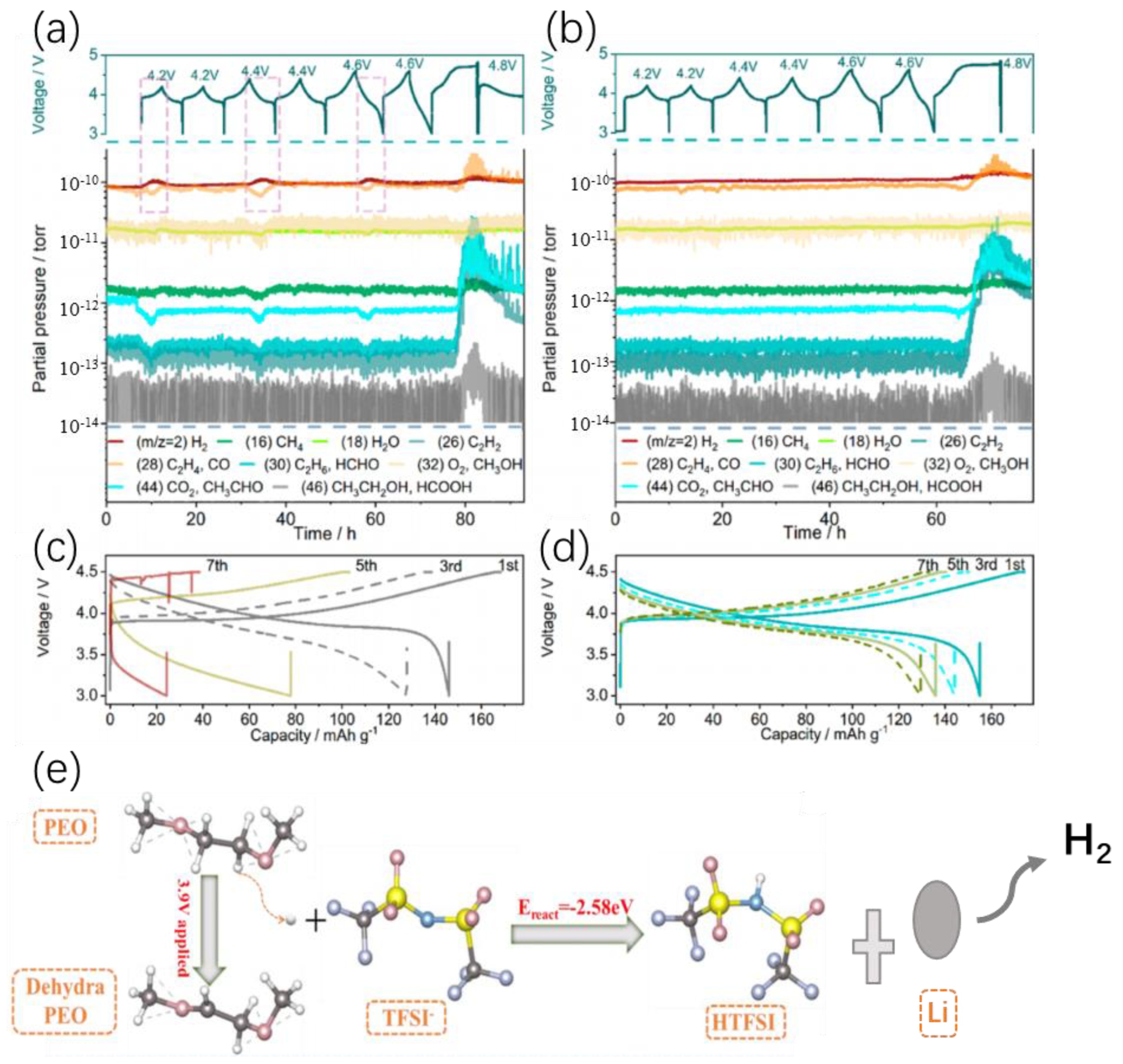
4.2.3. PEO-Based Polymer Electrolytes
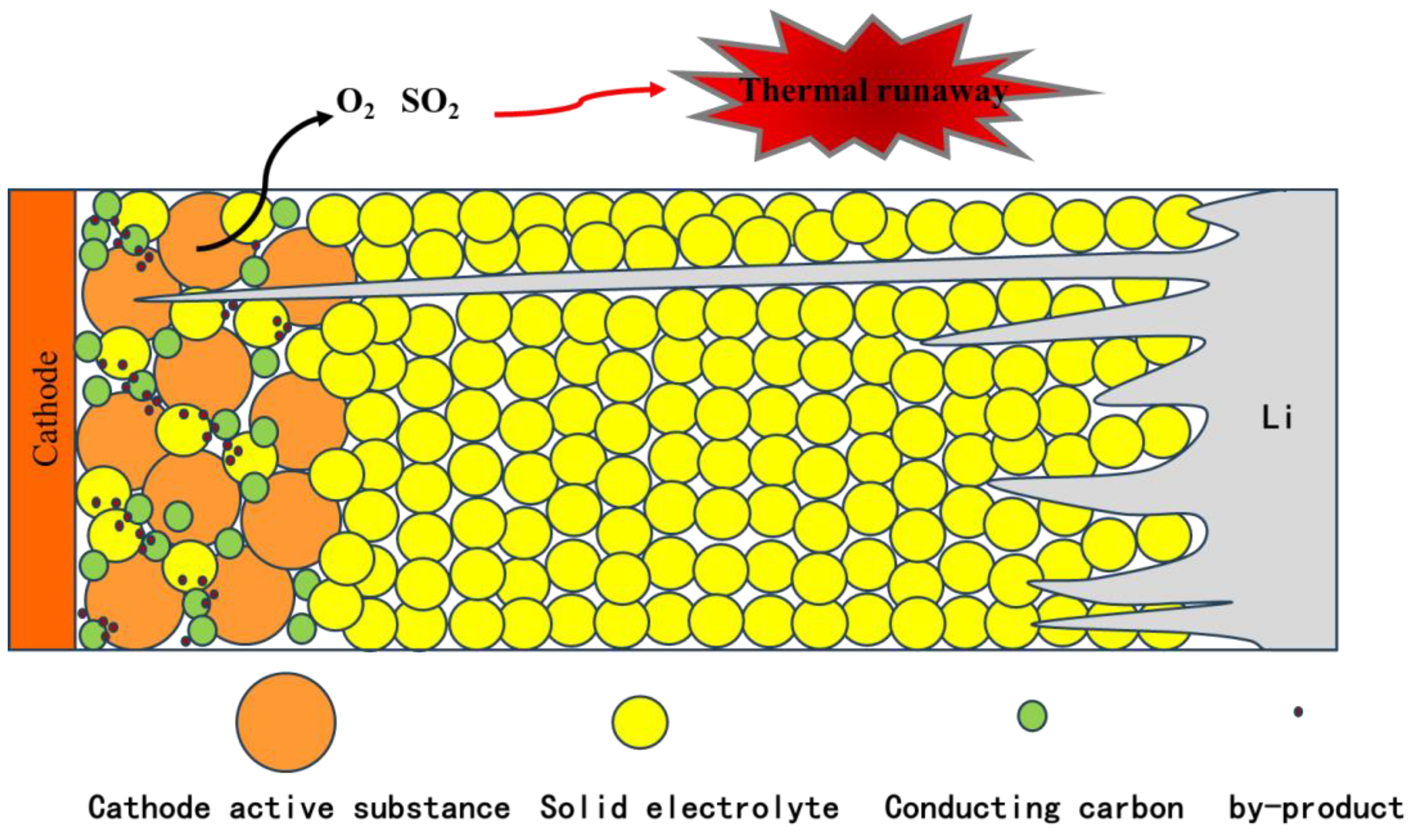
4.2.4. Gassing Behavior and Thermal Runway in SSB
5. Other Components
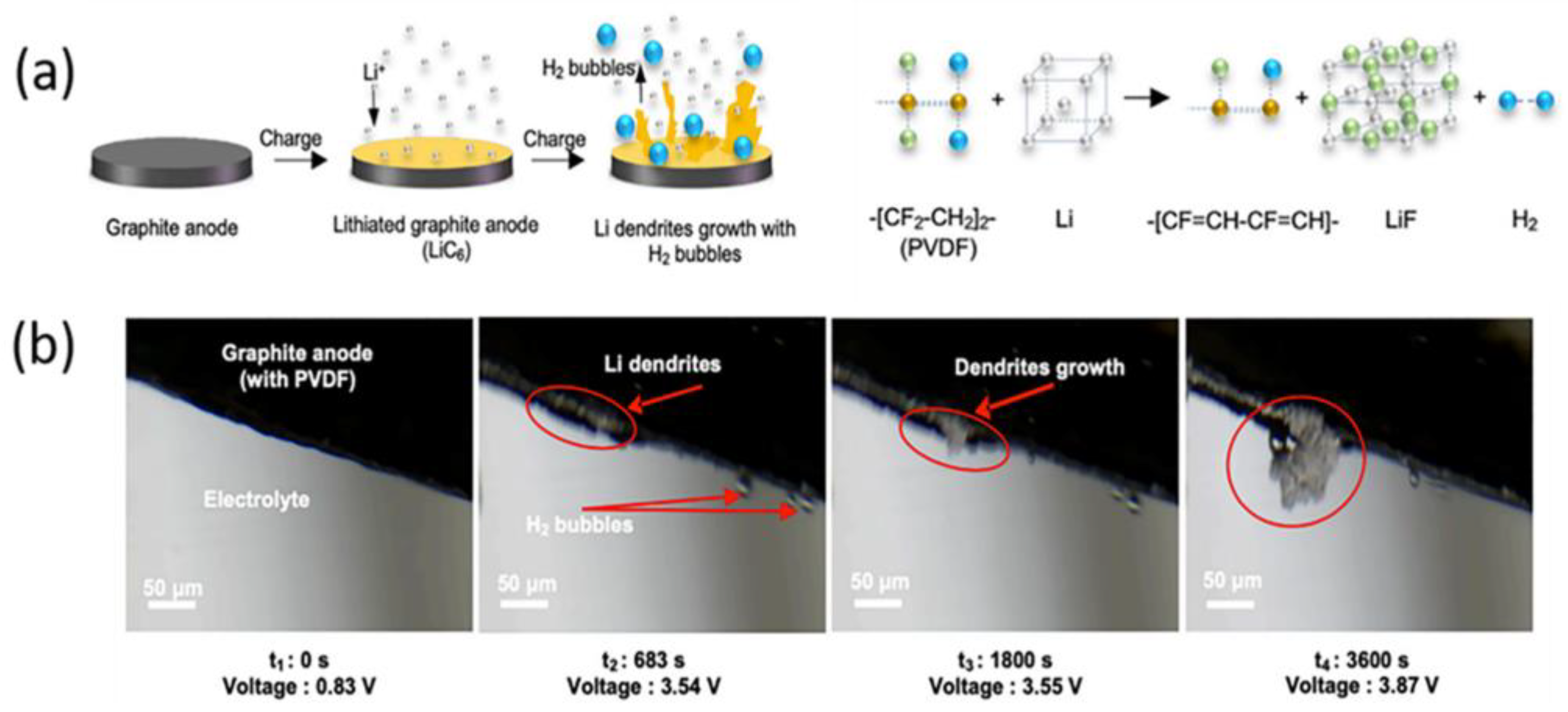
5.1. PVDF Binder
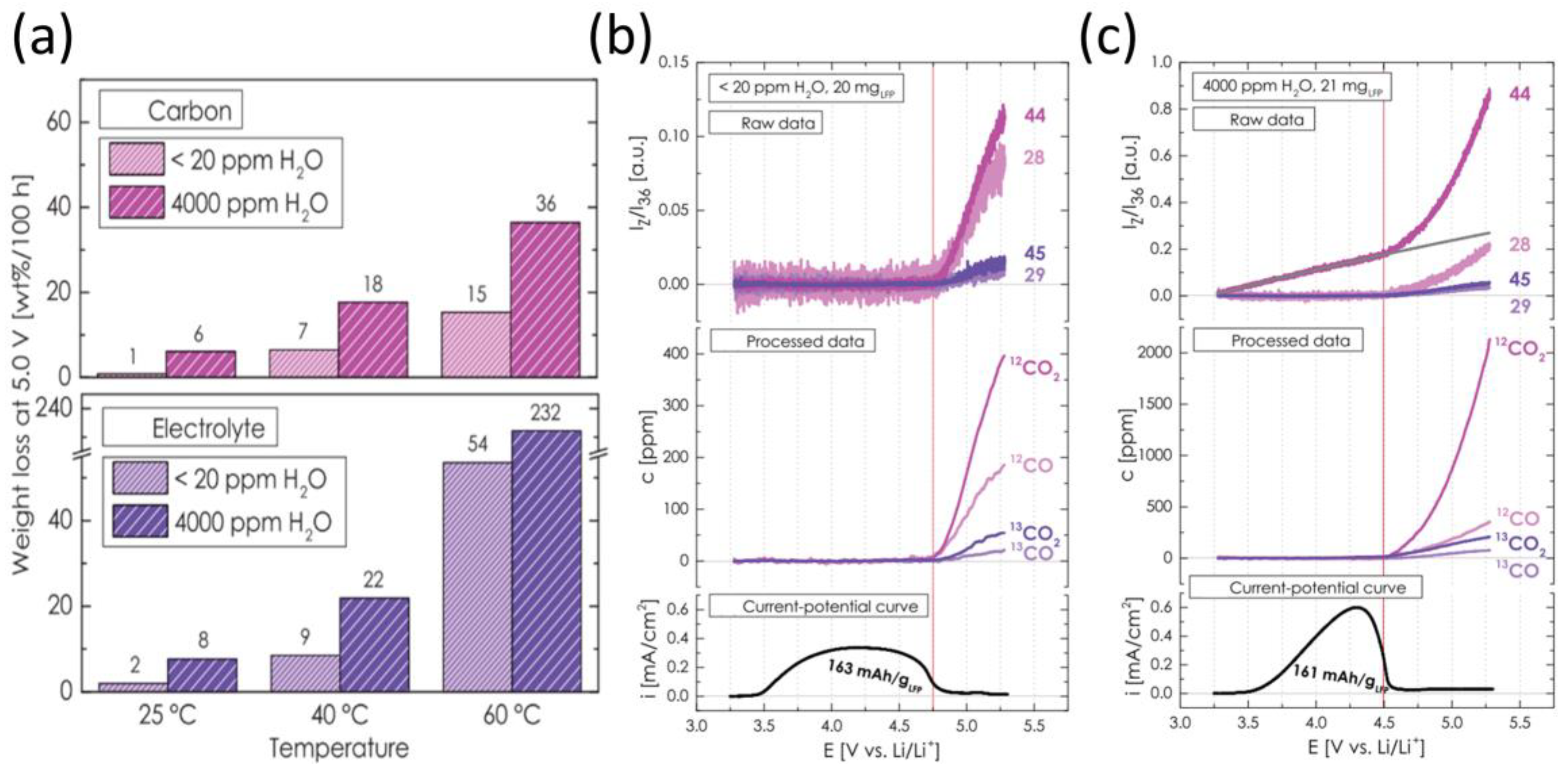
5.2. Conductive Carbon
5.3. Li2CO3
6. Conclusions and Perspectives
- Cathode materials: future strategies focus on stabilizing oxygen lattices and suppressing gas-inducing side reactions. Key approaches include dynamic oxygen reservoir engineering using redox mediators to trap released oxygen as solid intermediates, high-entropy cation/anion co-doping to disrupt oxygen migration pathways, and bio-inspired self-healing coatings that decompose reactive oxygen species. Advanced atomic-layer techniques will enable gradient oxygen coordination environments, dynamically adjusting bonding strength during cycling to prevent collective oxygen escape.
- Anode materials: innovations target lithium deposition control and volume expansion management. For lithium metal, electrocatalytic artificial SEI layers with embedded nanoparticles can homogenize Li+ flux while converting gaseous byproducts into solids. Silicon anodes require stress-adaptive 3D porous frameworks with gas-absorbing ionic liquid electrolytes to mitigate SEI cracking. Graphite modifications include anisotropic edge engineering to prevent low-temperature solvent co-intercalation and molecular sieve-integrated separators to trap gases before bubble formation.
- Cross-material synergy: emerging systems leverage electrode interactions for gas mitigation, such as coupling oxygen-scavenging cathode coatings with H2-absorbing anode additives to neutralize gaseous intermediates. Operando gas recycling could electrochemically reconvert CO2/O2 into SEI/CEI components, transforming gas into a self-healing resource. Integrated designs must combine atomic-scale simulations, multifunctional architectures, and closed-loop gas management to break the gas degradation cycle while advancing energy density.
- Electrolytes: beyond conventional LiPF6 optimization, two strategies are proposed: (i) high-entropy multi-salt systems to balance ion transport and interfacial stability, and (ii) solvation structure engineering to form gas-suppressing dense SEI/CEI layers. Solid-state electrolytes emerge as a transformative solution to minimize gas evolution.
- Auxiliary components: fluorine-free binders and surface-modified conductive agents (e.g., S-doped carbons) are prioritized to eliminate HF generation and redirect electrolyte decomposition toward solid-phase products.
Funding
Data Availability Statement
Conflicts of Interest
References
- Yan, W.; Ma, L.; Xu, J.; Guo, Y.; Hu, H.; Zhi, C.; Ho, D. Battery-Sensor Hybrid: A New Gas Sensing Paradigm with Complete Energy Self-Sufficiency. Acs Appl. Mater. Interfaces 2021, 13, 46507–46517. [Google Scholar] [CrossRef] [PubMed]
- Kong, W.; Zhang, J.; Wong, D.; Yang, W.; Yang, J.; Schulze, C.; Liu, X. Tailoring Co3d and O2p band centers to inhibit oxygen escape for stable 4.6V LiCoO2 cathodes. Angew. Chem. Int. Ed. Engl. 2021, 133, 27308–27318. [Google Scholar] [CrossRef]
- Schiele, A.; Breitung, B.; Hatsukade, T.; Berkes, B.B.; Hartmann, P.; Janek, J.; Brezesinski, T. The Critical Role of Fluoroethylene Carbonate in the Gassing of Silicon Anodes for Lithium-Ion Batteries. ACS Energy Lett. 2017, 2, 2228–2233. [Google Scholar] [CrossRef]
- Ge, B.; Hu, L.; Yu, X.; Wang, L.; Fernandez, C.; Yang, N.; Liang, Q.; Yang, Q.H. Engineering Triple-Phase Interfaces around the Anode toward Practical Alkali Metal–Air Batteries. Adv. Mater. 2024, 36, e2400937. [Google Scholar] [CrossRef]
- Chen, B.; Jiang, H.; Chen, X.; Li, H. Robust state-of-charge estimation for lithium-ion batteries based on an improved gas-liquid dynamics model. Energy 2022, 238, 122008. [Google Scholar] [CrossRef]
- Jozwiuk, A.; Berkes, B.B.; Weiss, T.; Sommer, H.; Janek, J.; Brezesinski, T. The critical role of lithium nitrate in the gas evolution of lithium-sulfur batteries. Energy Environ. Sci. 2016, 9, 2603–2608. [Google Scholar] [CrossRef]
- Zhou, L.T.; Zhang, W.K.; Wang, Y.F.; Liang, S.; Gan, Y.P.; Huang, H.; Zhang, J.; Xia, Y.; Liang, C. Lithium Sulfide as Cathode Materials for Lithium-Ion Batteries: Advances and Challenges. J. Chem. 2020, 2020, 17. [Google Scholar] [CrossRef]
- Stenzel, Y.; Horsthemke, F.; Winter, M.; Nowak, S. Chromatographic Techniques in the Research Area of Lithium Ion Batteries: Current State-of-the-Art. Separations 2019, 6, 26. [Google Scholar] [CrossRef]
- Long, J.J.; Yu, H.; Liu, W.B. Structure engineering of cathode host materials for Li-S batteries. Rare Met. 2024, 43, 1370–1389. [Google Scholar] [CrossRef]
- Goodenough, J.B.; Park, K.S. The Li-ion rechargeable battery: A perspective. J. Am. Chem. Soc. 2013, 135, 1167–1176. [Google Scholar] [CrossRef]
- Manthiram, A. A reflection on lithium-ion battery cathode chemistry. Nat. Commun. 2020, 11, 1550. [Google Scholar] [CrossRef] [PubMed]
- Golubkov, A.W.; Fuchs, D.; Wagner, J.; Wiltsche, H.; Stangl, C.; Fauler, G.; Voitic, G.; Thaler, A.; Hacker, V. Thermal-runaway experiments on consumer Li-ion batteries with metal-oxide and olivin-type cathodes. RSC Adv. 2014, 4, 3633–3642. [Google Scholar] [CrossRef]
- Luo, R.; Wang, C.; Zhang, Z.; Lv, W.; Wei, Z.; Zhang, Y.; Luo, X.; He, W. Three-Dimensional Nanoporous Polyethylene-Reinforced PVDF-HFP Separator Enabled by Dual-Solvent Hierarchical Gas Liberation for Ultrahigh-Rate Lithium Ion Batteries. Acs Appl. Energy Mater. 2018, 1, 921–927. [Google Scholar] [CrossRef]
- Kong, W.; Li, H.; Huang, X.; Chen, L. Gas evolution behaviors for several cathode materials in lithium-ion batteries. J. Power Sources 2005, 142, 285–291. [Google Scholar] [CrossRef]
- Jung, R.; Metzger, M.; Maglia, F.; Stinner, C.; Gasteiger, H.A. Oxygen Release and Its Effect on the Cycling Stability of LiNixMnyCozO2(NMC) Cathode Materials for Li-Ion Batteries. J. Electrochem. Soc. 2017, 164, A1361–A1377. [Google Scholar] [CrossRef]
- Self, J.; Aiken, C.P.; Petibon, R.; Dahn, J.R. Survey of Gas Expansion in Li-Ion NMC Pouch Cells. J. Electrochem. Soc. 2015, 162, A796–A802. [Google Scholar] [CrossRef]
- Berkes, B.B.; Jozwiuk, A.; Vračar, M.; Sommer, H.; Brezesinski, T.; Janek, J. Online Continuous Flow Differential Electrochemical Mass Spectrometry with a Realistic Battery Setup for High-Precision, Long-Term Cycling Tests. Anal. Chem. 2015, 87, 5878–5883. [Google Scholar] [CrossRef]
- Wandt, J.; Freiberg, A.T.S.; Ogrodnik, A.; Gasteiger, H.A. Singlet oxygen evolution from layered transition metal oxide cathode materials and its implications for lithium-ion batteries. Mater. Today 2018, 21, 825–833. [Google Scholar] [CrossRef]
- Geng, L.; Liu, J.; Wood, D.L.; Qin, Y.; Lu, W.; Jafta, C.J.; Bai, Y.; Belharouak, I. Probing Thermal Stability of Li-Ion Battery Ni-Rich Layered Oxide Cathodes by means of Operando Gas Analysis and Neutron Diffraction. ACS Appl. Energy Mater. 2020, 3, 7058–7065. [Google Scholar] [CrossRef]
- Wu, N.; Shen, J.; Zhou, X.; Li, S.; Li, J.; Liu, G.; Guo, D.; Deng, W.; Yuan, C.; Liu, X.; et al. Constructing Iron Vacancies in Thiospinel FeIn2S4 to Modulate Fe D-Band Center and Accelerate Sodiation Kinetics Enabling High-Rate and Durable Sodium Storage. Adv. Energy Mater. 2025, 2025, 2405729. [Google Scholar] [CrossRef]
- Back, C.K.; Yin, R.-Z.; Shin, S.-J.; Lee, Y.-S.; Choi, W.; Kim, Y.-S. Electrochemical Properties and Gas Evolution Behavior of Overlithiated Li2NiO2 as Cathode Active Mass for Rechargeable Li Ion Batteries. J. Electrochem. Soc. 2012, 159, A887–A893. [Google Scholar] [CrossRef]
- Belharouak, I.; Koenig, G.M.; Tan, T.; Yumoto, H.; Ota, N.; Amine, K. Performance Degradation and Gassing of Li4Ti5O12/LiMn2O4Lithium-Ion Cells. J. Electrochem. Soc. 2012, 159, A1165–A1170. [Google Scholar] [CrossRef]
- Belharouak, I.; Koenig, G.M.; Amine, K. Electrochemistry and safety of Li4Ti5O12 and graphite anodes paired with LiMn2O4 for hybrid electric vehicle Li-ion battery applications. J. Power Sources 2011, 196, 10344–10350. [Google Scholar] [CrossRef]
- Golubkov, A.W.; Scheikl, S.; Planteu, R.; Voitic, G.; Wiltsche, H.; Stangl, C.; Fauler, G.; Thaler, A.; Hacker, V. Thermal runaway of commercial 18650 Li-ion batteries with LFP and NCA cathodes—Impact of state of charge and overcharge. RSC Adv. 2015, 5, 57171–57186. [Google Scholar] [CrossRef]
- Lee, Y.K. Effect of transition metal ions on solid electrolyte interphase layer on the graphite electrode in lithium ion battery. J. Power Sources 2021, 484, 229270. [Google Scholar] [CrossRef]
- Shin, H.; Park, J.; Sastry, A.M.; Lu, W. Degradation of the solid electrolyte interphase induced by the deposition of manganese ions. J. Power Sources 2015, 284, 416–427. [Google Scholar] [CrossRef]
- Xie, Y.; Li, W.; Hu, H.; Shi, C.-G.; Hong, Y.-H.; Dai, P.; Lin, Z.; Sha, Y.; Wang, J.; Xie, L.; et al. Unraveling the Roles of Dissolved Mn(2+) and Its Impact on the Electrode–Electrolyte Interface under Realistic Conditions. ACS Sustain. Chem. Eng. 2024, 12, 6529–6538. [Google Scholar] [CrossRef]
- Zhao, Q.-f.; Yu, Y.-h.; Ouyang, Q.-s.; Hu, M.-y.; Wang, C.; Ge, J.-h.; Zhang, S.-q.; Jiang, G.-h. Surface modification of LiFePO4 by Coatings for Improving of Lithium-ion Battery Properties. Int. J. Electrochem. Sci. 2022, 17, 221142. [Google Scholar] [CrossRef]
- Harold, U.; Escobar-Hernandez, R.M.G.; Papadaki, M.I.; Sachdeva, S.; Mannan, M.S. Thermal Runaway in Lithium-Ion Batteries: Incidents, Kinetics of the Runaway and Assessment of Factors Affecting Its Initiation. J. Electrochem. Soc. 2016, 163, A2691–A2701. [Google Scholar]
- Zhang, Y.; Wang, H.; Yu, H.; Jia, T.; Ma, C. Influence of Cathode Materials on the Characteristics of Lithium-Ion Battery Gas Generation During Thermal Runaway. Fire Technol. 2024. [Google Scholar] [CrossRef]
- Chen, J.; Xu, C.; Wang, Q.; Wang, H.; Peng, Y.; Liu, J.; Zhang, J.; Zhang, G.; Lu, L.; Feng, X. The thermal-gas coupling mechanism of lithium iron phosphate batteries during thermal runaway. J. Power Sources 2025, 625, 235728. [Google Scholar] [CrossRef]
- Zhang, H.; Xue, J.; Qin, Y.; Chen, J.; Wang, J.; Yu, X.; Zhang, B.; Zou, Y.; Hong, Y.H.; Li, Z.; et al. Full-Dimensional Analysis of Gaseous Products to Unlocking In Depth Thermal Runaway Mechanism of Li-Ion Batteries. Small 2024, 20, e2406110. [Google Scholar] [CrossRef] [PubMed]
- Jia, Z.; Qin, P.; Li, Z.; Wei, Z.; Jin, K.; Jiang, L.; Wang, Q. Analysis of gas release during the process of thermal runaway of lithium-ion batteries with three different cathode materials. J. Energy Storage 2022, 50, 104302. [Google Scholar] [CrossRef]
- Dong, T.; Xu, G.; Xie, B.; Liu, T.; Gong, T.; Sun, C.; Wang, J.; Zhang, S.; Zhang, X.; Zhang, H.; et al. An Electrode-Crosstalk-Suppressing Smart Polymer Electrolyte for High Safety Lithium-Ion Batteries. Adv. Mater. 2024, 36, 2400737. [Google Scholar] [CrossRef]
- Zhou, Y.M.; Wang, P.Y.; Wang, K.; Fang, X.D.; Li, W.; Nai, J.; Liu, Y.J.; Wang, Y.; Zou, S.H.; Yuan, H.D.; et al. Developing High-Performance Anode-Free Lithium Batteries: Challenges, Strategies, and Opportunities. Adv. Funct. Mater. 2025, 30, 2424022. [Google Scholar] [CrossRef]
- Zhao, H.J.; Deng, N.P.; Yan, J.; Kang, W.M.; Ju, J.G.; Ruan, Y.L.; Wang, X.Q.; Zhuang, X.P.; Li, Q.X.; Cheng, B.W. A review on anode for lithium-sulfur batteries: Progress and prospects. Chem. Eng. J. 2018, 347, 343–365. [Google Scholar] [CrossRef]
- Yi, X.P.; Qi, G.Q.; Liu, X.L.; Depcik, C.; Liu, L. Challenges and strategies toward anode materials with different lithium storage mechanisms for rechargeable lithium batteries. J. Energy Storage 2024, 95, 23. [Google Scholar] [CrossRef]
- Shen, Z.; Huang, J.; Xie, Y.; Wei, D.; Chen, J.; Shi, Z. Solid Electrolyte Interphase on Lithium Metal Anodes. ChemSusChem 2024, 17, e202301777. [Google Scholar] [CrossRef]
- Kim, M.; You, H.M.; Jeon, J.; Lim, J.; Han, Y.; Kim, K.; Hong, J. Thermal decomposition mechanism of lithium methyl carbonate in solid electrolyte interphase layer of lithium-ion battery. Energy Storage Mater. 2024, 70, 103517. [Google Scholar] [CrossRef]
- Parimalam, B.S.; MacIntosh, A.D.; Kadam, R.; Lucht, B.L. Decomposition Reactions of Anode Solid Electrolyte Interphase (SEI) Components with LiPF6. J. Phys. Chem. C 2017, 121, 22733–22738. [Google Scholar] [CrossRef]
- Wu, J.; Weng, S.; Zhang, X.; Sun, W.; Wu, W.; Wang, Q.; Yu, X.; Chen, L.; Wang, Z.; Wang, X. In Situ Detecting Thermal Stability of Solid Electrolyte Interphase (SEI). Small 2023, 19, e2208239. [Google Scholar] [CrossRef]
- Wu, N.; He, W.; Shi, S.; Yuan, X.; Li, J.; Cao, J.; Yuan, C.; Liu, X. Bamboo fiber-derived carbon support for the immobilization of Pt nanoparticles to enhance hydrogen evolution reaction. J. Colloid Interface Sci. 2025, 684, 658–667. [Google Scholar] [CrossRef] [PubMed]
- Liu, X.; Yin, L.; Ren, D.; Wang, L.; Ren, Y.; Xu, W.; Lapidus, S.; Wang, H.; He, X.; Chen, Z.; et al. In situ observation of thermal-driven degradation and safety concerns of lithiated graphite anode. Nat. Commun. 2021, 12, 4235. [Google Scholar] [CrossRef]
- Fernandes, Y.; Bry, A.; de Persis, S. Identification and quantification of gases emitted during abuse tests by overcharge of a commercial Li-ion battery. J. Power Sources 2018, 389, 106–119. [Google Scholar] [CrossRef]
- Bernhard, R.; Metzger, M.; Gasteiger, H.A. Gas Evolution at Graphite Anodes Depending on Electrolyte Water Content and SEI Quality Studied by On-Line Electrochemical Mass Spectrometry. J. Electrochem. Soc. 2015, 162, A1984–A1989. [Google Scholar] [CrossRef]
- Michalak, B.; Sommer, H.; Mannes, D.; Kaestner, A.; Brezesinski, T.; Janek, J. Gas evolution in operating lithium-ion batteries studied in situ by neutron imaging. Sci. Rep. 2015, 5, 15627. [Google Scholar] [CrossRef] [PubMed]
- Schwenke, K.U.; Solchenbach, S.; Demeaux, J.; Lucht, B.L.; Gasteiger, H.A. The Impact of CO2 Evolved from VC and FEC during Formation of Graphite Anodes in Lithium-Ion Batteries. J. Electrochem. Soc. 2019, 166, A2035–A2047. [Google Scholar] [CrossRef]
- Han, R.; Wang, Z.; Huang, D.; Zhang, F.; Pan, A.; Song, H.; Wei, Y.; Liu, Y.; Wang, L.; Li, Y.; et al. High-Energy-Density Lithium Metal Batteries with Impressive Li(+) Transport Dynamic and Wide-Temperature Performance from −60 to 60 degrees C. Small 2023, 19, e2300571. [Google Scholar] [CrossRef] [PubMed]
- Zhang, H.; Wu, X.; Li, Z.; Zou, Y.; Wang, J.; Yu, X.; Chen, J.; Xue, J.; Zhang, B.; Tian, J.H.; et al. Full-Dimensional Analysis of Gaseous Products Within Li-Ion Batteries by On-Line GC-BID/MS. Adv. Energy Mater. 2024, 14, 2400397. [Google Scholar] [CrossRef]
- Huang, Y.; Yang, H.; Gao, Y.; Chen, G.; Li, Y.; Shi, L.; Zhang, D. Mechanism and solutions of lithium dendrite growth in lithium metal batteries. Mater. Chem. Front. 2024, 8, 1282–1299. [Google Scholar] [CrossRef]
- Wang, S.; Rafiz, K.; Liu, J.; Jin, Y.; Lin, J.Y.S. Effects of lithium dendrites on thermal runaway and gassing of LiFePO4 batteries. Sustain. Energy Fuels 2020, 4, 2342–2351. [Google Scholar] [CrossRef]
- Zhang, G.; Wei, X.; Han, G.; Dai, H.; Zhu, J.; Wang, X.; Tang, X.; Ye, J. Lithium plating on the anode for lithium-ion batteries during long-term low temperature cycling. J. Power Sources 2021, 484, 229312. [Google Scholar] [CrossRef]
- Berckmans, G.; De Sutter, L.; Kersys, A.; Kriston, A.; Marinaro, M.; Kasper, M.; Axmann, P.; Smekens, J.; Wohlfahrt-Mehrens, M.; Pfrang, A.; et al. Electrical Characterization and Micro X-ray Computed Tomography Analysis of Next-Generation Silicon Alloy Lithium-Ion Cells. World Electr. Veh. J. 2018, 9, 43. [Google Scholar] [CrossRef]
- Zhang, L.Q.; Zhu, C.X.; Yu, S.C.; Ge, D.H.; Zhou, H.S. Status and challenges facing representative anode materials for rechargeable lithium batteries. J. Energy Chem. 2022, 66, 260–294. [Google Scholar] [CrossRef]
- Khan, M.; Yan, S.; Ali, M.; Mahmood, F.; Zheng, Y.; Li, G.; Liu, J.; Song, X.; Wang, Y. Innovative Solutions for High-Performance Silicon Anodes in Lithium-Ion Batteries: Overcoming Challenges and Real-World Applications. Nanomicro Lett. 2024, 16, 179. [Google Scholar] [CrossRef]
- Sun, Y.; Liu, K.; Zhu, Y. Recent Progress in Synthesis and Application of Low-Dimensional Silicon Based Anode Material for Lithium Ion Battery. J. Nanomater. 2017, 2017, 1–15. [Google Scholar] [CrossRef]
- Shen, X.; Liu, H.; Cheng, X.-B.; Yan, C.; Huang, J.-Q. Beyond lithium ion batteries: Higher energy density battery systems based on lithium metal anodes. Energy Storage Mater. 2018, 12, 161–175. [Google Scholar] [CrossRef]
- Gao, Y.; Guo, M.; Yuan, K.; Shen, C.; Ren, Z.; Zhang, K.; Zhao, H.; Qiao, F.; Gu, J.; Qi, Y.; et al. Multifunctional Silanization Interface for High-Energy and Low-Gassing Lithium Metal Pouch Cells. Adv. Energy Mater. 2019, 10, 1903362. [Google Scholar] [CrossRef]
- Peng, Y.; Ding, M.; Zhang, K.; Zhang, H.; Hu, Y.; Lin, Y.; Hu, W.; Liao, Y.; Tang, S.; Liang, J.; et al. Quantitative Analysis of the Coupled Mechanisms of Lithium Plating, SEI Growth, and Electrolyte Decomposition in Fast Charging Battery. ACS Energy Lett. 2024, 9, 6022–6028. [Google Scholar] [CrossRef]
- Zhao, H.; Wang, J.; Shao, H.; Xu, K.; Deng, Y. Gas Generation Mechanism in Li-Metal Batteries. Energy Environ. Mater. 2021, 5, 327–336. [Google Scholar] [CrossRef]
- Etxebarria, A.; Yun, D.-J.; Blum, M.; Ye, Y.; Sun, M.; Lee, K.-J.; Su, H.; Muñoz-Márquez, M.Á.; Ross, P.N.; Crumlin, E.J. Revealing In Situ Li Metal Anode Surface Evolution upon Exposure to CO2 Using Ambient Pressure X-Ray Photoelectron Spectroscopy. ACS Appl. Mater. Interfaces 2020, 12, 26607–26613. [Google Scholar] [CrossRef] [PubMed]
- Chen, X.; Hou, T.-Z.; Li, B.; Yan, C.; Zhu, L.; Guan, C.; Cheng, X.-B.; Peng, H.-J.; Huang, J.-Q.; Zhang, Q. Towards stable lithium-sulfur batteries: Mechanistic insights into electrolyte decomposition on lithium metal anode. Energy Storage Mater. 2017, 8, 194–201. [Google Scholar] [CrossRef]
- Nagar, A.; Garg, A.; Singh, S.; Gao, L.; Kim, J.; Wei, K. Reactive Force Field (ReaxFF) and Universal Force Field Molecular Dynamic Simulation of Solid Electrolyte Interphase Components in Lithium-Ion Batteries. J. Electrochem. Energy Convers. Storage 2024, 21, 021006. [Google Scholar] [CrossRef]
- Jo, S.; Seo, S.; Kang, S.K.; Na, I.; Kunze, S.; Song, M.; Hwang, S.; Woo, S.P.; Kim, S.; Kim, W.B.; et al. Thermal Runaway Mechanism in Ni-Rich Cathode Full Cells of Lithium-Ion Batteries: The Role of Multidirectional Crosstalk. Adv. Mater. 2024, 36, e2402024. [Google Scholar] [CrossRef]
- He, Y.-B.; Li, B.; Liu, M.; Zhang, C.; Lv, W.; Yang, C.; Li, J.; Du, H.; Zhang, B.; Yang, Q.-H.; et al. Gassing in Li4Ti5O12-based batteries and its remedy. Sci. Rep. 2012, 2, 913. [Google Scholar] [CrossRef]
- Hu, Q.; He, Y.; Ren, D.; Song, Y.; Wu, Y.; Liang, H.; Gao, J.; Xu, G.; Cai, J.; Li, T.; et al. Targeted masking enables stable cycling of LiNi0.6Co0.2Mn0.2O2 at 4.6V. Nano Energy 2022, 96, 107123. [Google Scholar] [CrossRef]
- Mu, X.W.; Ding, H.L.; Wu, Y.D.; Hu, H.B.; Yu, B. Nonflammable Liquid Electrolytes for Safe Lithium Batteries. Small Struct. 2023, 4, 13. [Google Scholar] [CrossRef]
- Xu, G.J.; Shangguan, X.H.; Dong, S.M.; Zhou, X.H.; Cui, G.L. Formulation of Blended-Lithium-Salt Electrolytes for Lithium Batteries. Angew. Chem.-Int. Ed. 2020, 59, 3400–3415. [Google Scholar] [CrossRef]
- Zhou, G.; Niu, C.; Kong, Y.; Wei, Z.; Wang, J.; Huang, Q.; Lu, H.; Zhang, Q. Research on stimulation responsive electrolytes from the perspective of thermal runaway in lithium-ion batteries: A review. Fuel 2024, 368, 131599. [Google Scholar] [CrossRef]
- Han, Z.; Zhang, D.; Wang, H.; Zheng, G.; Liu, M.; He, Y. Research Progress and Prospect on Electrolyte Additives for Interface Reconstruction of Long-Life Ni-Rich Lithium Batteries. Acta Phys.-Chim. Sin. 2024, 40, 2307034. [Google Scholar] [CrossRef]
- Kriston, A.; Adanouj, I.; Ruiz, V.; Pfrang, A. Quantification and simulation of thermal decomposition reactions of Li-ion battery materials by simultaneous thermal analysis coupled with gas analysis. J. Power Sources 2019, 435, 226774. [Google Scholar] [CrossRef]
- Schmitz, R.W.; Murmann, P.; Schmitz, R.; Müller, R.; Krämer, L.; Kasnatscheew, J.; Isken, P.; Niehoff, P.; Nowak, S.; Röschenthaler, G.-V.; et al. Investigations on novel electrolytes, solvents and SEI additives for use in lithium-ion batteries: Systematic electrochemical characterization and detailed analysis by spectroscopic methods. Prog. Solid State Chem. 2014, 42, 65–84. [Google Scholar] [CrossRef]
- Inamoto, J.-I.; Fukutsuka, T.; Miyazaki, K.; Abe, T. Investigation on Surface-Film Formation Behavior of LiMn2O4 Thin-Film Electrodes in LiClO4/Propylene Carbonate. ChemistrySelect 2017, 2, 2895–2900. [Google Scholar] [CrossRef]
- Wang, C.; Zhang, H.; Li, J.; Chai, J.; Dong, S.; Cui, G. The interfacial evolution between polycarbonate-based polymer electrolyte and Li-metal anode. J. Power Sources 2018, 397, 157–161. [Google Scholar] [CrossRef]
- Liao, Z.; Zhang, S.; Zhao, Y.; Qiu, Z.; Li, K.; Han, D.; Zhang, G.; Habetler, T.G. Experimental evaluation of thermolysis-driven gas emissions from LiPF6-carbonate electrolyte used in lithium-ion batteries. J. Energy Chem. 2020, 49, 124–135. [Google Scholar] [CrossRef]
- Liu, Y.M.; Nicolau, B.G.; Esbenshade, J.L.; Gewirth, A.A. Characterization of the Cathode Electrolyte Interface in Lithium Ion Batteries by Desorption Electrospray Ionization Mass Spectrometry. Anal. Chem. 2016, 88, 7171–7177. [Google Scholar] [CrossRef] [PubMed]
- Melin, T.; Lundström, R.; Berg, E.J. Revisiting the Ethylene Carbonate–Propylene Carbonate Mystery with Operando Characterization. Adv. Mater. Interfaces 2021, 9, 2101258. [Google Scholar] [CrossRef]
- Yang, H.; Zhuang, G.V.; Ross, P.N. Thermal stability of LiPF6 salt and Li-ion battery electrolytes containing LiPF6. J. Power Sources 2006, 161, 573–579. [Google Scholar] [CrossRef]
- Liao, Y.; Zhang, H.; Peng, Y.; Hu, Y.; Liang, J.; Gong, Z.; Wei, Y.; Yang, Y. Electrolyte Degradation During Aging Process of Lithium-Ion Batteries: Mechanisms, Characterization, and Quantitative Analysis. Adv. Energy Mater. 2024, 14, 2304295. [Google Scholar] [CrossRef]
- Ortiz, D.; Steinmetz, V.; Durand, D.; Legand, S.; Dauvois, V.; Maitre, P.; Le Caer, S. Radiolysis as a solution for accelerated ageing studies of electrolytes in Lithium-ion batteries. Nat. Commun. 2015, 6, 6950. [Google Scholar] [CrossRef]
- Liu, P.; Yang, L.; Xiao, B.; Wang, H.; Li, L.; Ye, S.; Li, Y.; Ren, X.; Ouyang, X.; Hu, J.; et al. Revealing Lithium Battery Gas Generation for Safer Practical Applications. Adv. Funct. Mater. 2022, 32, 2208586. [Google Scholar] [CrossRef]
- Han, J.G.; Kim, K.; Lee, Y.; Choi, N.S. Scavenging Materials to Stabilize LiPF(6) -Containing Carbonate-Based Electrolytes for Li-Ion Batteries. Adv. Mater. 2019, 31, e1804822. [Google Scholar] [CrossRef] [PubMed]
- Tebbe, J.L.; Fuerst, T.F.; Musgrave, C.B. Mechanism of hydrofluoric acid formation in ethylene carbonate electrolytes with fluorine salt additives. J. Power Sources 2015, 297, 427–435. [Google Scholar] [CrossRef]
- Larsson, F.; Andersson, P.; Blomqvist, P.; Mellander, B.E. Toxic fluoride gas emissions from lithium-ion battery fires. Sci. Rep. 2017, 7, 10018. [Google Scholar] [CrossRef]
- Agubra, V.A.; Fergus, J.W. The formation and stability of the solid electrolyte interface on the graphite anode. J. Power Sources 2014, 268, 153–162. [Google Scholar] [CrossRef]
- Wu, J.; Liu, S.; Han, F.; Yao, X.; Wang, C. Lithium/Sulfide All-Solid-State Batteries using Sulfide Electrolytes. Adv. Mater. 2021, 33, e2000751. [Google Scholar] [CrossRef]
- Wu, N.; Zhao, Z.; Zhang, Y.; Hua, R.; Li, J.; Liu, G.; Guo, D.; Zhao, J.; Cao, A.; Sun, G.; et al. Revealing the fast reaction kinetics and interfacial behaviors of CuFeS2 hollow nanorods for durable and high-rate sodium storage. J. Colloid Interface Sci. 2025, 679, 990–1000. [Google Scholar] [CrossRef] [PubMed]
- Ito, A.; Kimura, T.; Sakuda, A.; Tatsumisago, M.; Hayashi, A. Liquid-phase synthesis of Li3PS4 solid electrolyte using ethylenediamine. J. Sol-Gel Sci. Technol. 2021, 101, 2–7. [Google Scholar] [CrossRef]
- Yersak, T.A.; Gonzalez Malabet, H.J.; Yadav, V.; Pieczonka, N.P.W.; Collin, W.; Cai, M. Flammability of sulfide solid-state electrolytes β-Li3PS4 and Li6PS5Cl: Volatilization and autoignition of sulfur vapor—New insight into all-solid-state battery thermal runaway. J. Energy Chem. 2025, 102, 651–660. [Google Scholar] [CrossRef]
- Lee, E.; Kim, H.; Choi, H.; Kim, S.Y.; Chung, K.Y. Unraveling the reversible redox mechanism of Li(6)PS(5)Cl solid electrolyte in all-solid-state lithium-sulfur batteries. Chem. Commun. 2024, 60, 14834–14837. [Google Scholar] [CrossRef]
- Nikodimos, Y.; Huang, C.-J.; Taklu, B.W.; Su, W.-N.; Hwang, B.J. Chemical stability of sulfide solid-state electrolytes: Stability toward humid air and compatibility with solvents and binders. Energy Environ. Sci. 2022, 15, 991–1033. [Google Scholar] [CrossRef]
- Lu, P.; Liu, L.; Wang, S.; Xu, J.; Peng, J.; Yan, W.; Wang, Q.; Li, H.; Chen, L.; Wu, F. Superior All-Solid-State Batteries Enabled by a Gas-Phase-Synthesized Sulfide Electrolyte with Ultrahigh Moisture Stability and Ionic Conductivity. Adv. Mater. 2021, 33, 2100921. [Google Scholar] [CrossRef] [PubMed]
- Sun, Y.Z.; Huang, J.Q.; Zhao, C.Z.; Zhang, Q. A review of solid electrolytes for safe lithium-sulfur batteries. Sci. China-Chem. 2017, 60, 1508–1526. [Google Scholar] [CrossRef]
- Takada, K. Progress in solid electrolytes toward realizing solid-state lithium batteries. J. Power Sources 2018, 394, 74–85. [Google Scholar] [CrossRef]
- Indu, M.S.; Alexander, G.V.; Sreejith, O.V.; Abraham, S.E.; Murugan, R. Lithium garnet-cathode interfacial chemistry: Inclusive insights and outlook toward practical solid-state lithium metal batteries. Mater. Today Energy 2021, 21, 46. [Google Scholar] [CrossRef]
- Hou, W.; Ou, Y.; Liu, K. Progress on High Voltage PEO-based Polymer Solid Electrolytes in Lithium Batteries. Chem. Res. Chin. Univ. 2022, 38, 735–743. [Google Scholar] [CrossRef]
- Hubble, D.; Brown, D.E.; Zhao, Y.; Fang, C.; Lau, J.; McCloskey, B.D.; Liu, G. Liquid electrolyte development for low-temperature lithium-ion batteries. Energy Environ. Sci. 2022, 15, 550–578. [Google Scholar] [CrossRef]
- Wang, C.; Yang, Y.; Liu, X.; Zhong, H.; Xu, H.; Xu, Z.; Shao, H.; Ding, F. Suppression of Lithium Dendrite Formation by Using LAGP-PEO (LiTFSI) Composite Solid Electrolyte and Lithium Metal Anode Modified by PEO (LiTFSI) in All-Solid-State Lithium Batteries. ACS Appl. Mater. Interfaces 2017, 9, 13694–13702. [Google Scholar] [CrossRef] [PubMed]
- Yi, M.; Li, J.; Wang, M.; Fan, X.; Hong, B.; Zhang, Z.; Zhang, Z.; Jiang, H.; Wang, A.; Lai, Y. Suppressing structural degradation of single crystal nickel-rich cathodes in PEO-based all-solid-state batteries: Mechanistic insight and performance. Energy Storage Mater. 2023, 54, 579–588. [Google Scholar] [CrossRef]
- Nie, K.; Wang, X.; Qiu, J.; Wang, Y.; Yang, Q.; Xu, J.; Yu, X.; Li, H.; Huang, X.; Chen, L. Increasing Poly(ethylene oxide) Stability to 4.5 V by Surface Coating of the Cathode. ACS Energy Lett. 2020, 5, 826–832. [Google Scholar] [CrossRef]
- Barbosa, J.C.; Dias, J.P.; Lanceros-Mendez, S.; Costa, C.M. Recent Advances in Poly(vinylidene fluoride) and Its Copolymers for Lithium-Ion Battery Separators. Membranes 2018, 8, 45. [Google Scholar] [CrossRef] [PubMed]
- Song, L.; Xiong, Y.; Xiao, Z.; Li, A.; Yan, L.; Kuang, Y.; Zhao, T. Research progress on the mechanism and key role of filler structure on properties of PVDF composite solid electrolyte. Ionics 2024, 30, 5861–5877. [Google Scholar] [CrossRef]
- Jin, Y.; Zheng, Z.; Wei, D.; Jiang, X.; Lu, H.; Sun, L.; Tao, F.; Guo, D.; Liu, Y.; Gao, J.; et al. Detection of Micro-Scale Li Dendrite via H2 Gas Capture for Early Safety Warning. Joule 2020, 4, 1714–1729. [Google Scholar] [CrossRef]
- Fell, C.R.; Sun, L.; Hallac, P.B.; Metz, B.; Sisk, B. Investigation of the Gas Generation in Lithium Titanate Anode Based Lithium Ion Batteries. J. Electrochem. Soc. 2015, 162, A1916–A1920. [Google Scholar] [CrossRef]
- Wu, Y.; Liu, X.; Wang, L.; Feng, X.; Ren, D.; Li, Y.; Rui, X.; Wang, Y.; Han, X.; Xu, G.-L.; et al. Development of cathode-electrolyte-interphase for safer lithium batteries. Energy Storage Mater. 2021, 37, 77–86. [Google Scholar] [CrossRef]
- Guo, X.-X.; Li, Y.-Q.; Cui, Z.-H.; Rui, F.; Ning, Z.; Du, F.-M. Influence of Electronic Conducting Additives on Cycle Performance of Garnet-based Solid Lithium Batteries. J. Inorg. Mater. 2018, 33, 462–470. [Google Scholar]
- Metzger, M.; Marino, C.; Sicklinger, J.; Haering, D.; Gasteiger, H.A. Anodic Oxidation of Conductive Carbon and Ethylene Carbonate in High-Voltage Li-Ion Batteries Quantified by On-Line Electrochemical Mass Spectrometry. J. Electrochem. Soc. 2015, 162, A1123–A1134. [Google Scholar] [CrossRef]
- Metzger, M.; Sicklinger, J.; Haering, D.; Kavakli, C.; Stinner, C.; Marino, C.; Gasteiger, H.A. Carbon Coating Stability on High-Voltage Cathode Materials in H2O-Free and H2O-Containing Electrolyte. J. Electrochem. Soc. 2015, 162, A1227–A1235. [Google Scholar] [CrossRef]
- Kajiyama, A.; Masaki, R.; Wakiyama, T.; Matsumoto, K.; Yoda, A.; Inada, T.; Yokota, H.; Kanno, R. Principal Factors of Carbon Conductive Agents that Contribute to the Gas Formation in High-Voltage Cathode Systems. J. Electrochem. Soc. 2015, 162, A1516–A1522. [Google Scholar] [CrossRef]
- Salomez, B.; Grugeon, S.; Armand, M.; Tran-Van, P.; Laruelle, S. Review—Gassing Mechanisms in Lithium-ion Battery. J. Electrochem. Soc. 2023, 170, 050537. [Google Scholar] [CrossRef]
- Renfrew, S.E.; McCloskey, B.D. Residual Lithium Carbonate Predominantly Accounts for First Cycle CO2 and CO Outgassing of Li-Stoichiometric and Li-Rich Layered Transition-Metal Oxides. J. Am. Chem. Soc. 2017, 139, 17853–17860. [Google Scholar] [CrossRef] [PubMed]
- Mahne, N.; Renfrew, S.E.; McCloskey, B.D.; Freunberger, S.A. Electrochemical Oxidation of Lithium Carbonate Generates Singlet Oxygen. Angew. Chem. Int. Ed. 2018, 57, 5529–5533. [Google Scholar] [CrossRef] [PubMed]
- Zhuang, X.; Zhang, S.; Cui, Z.; Xie, B.; Gong, T.; Zhang, X.; Li, J.; Wu, R.; Wang, S.; Qiao, L.; et al. Interphase Regulation by Multifunctional Additive Empowering High Energy Lithium-Ion Batteries with Enhanced Cycle Life and Thermal Safety. Angew. Chem. Int. Ed. 2023, 63, e202315710. [Google Scholar] [CrossRef]
- Sun, J.; Chen, G.; Wang, B.; Li, J.; Xu, G.; Wu, T.; Tang, Y.; Dong, S.; Huang, J.; Cui, G. Lithium Hydride in the Solid Electrolyte Interphase of Lithium-Ion Batteries as a Pulverization Accelerator of Silicon. Angew. Chem. Int. Ed. 2024, 63, e202406198. [Google Scholar] [CrossRef]
- Wang, Q.; Ping, P.; Zhao, X.; Chu, G.; Sun, J.; Chen, C. Thermal runaway caused fire and explosion of lithium ion battery. J. Power Sources 2012, 208, 210–224. [Google Scholar] [CrossRef]
- Wang, Z.; He, T.; Bian, H.; Jiang, F.; Yang, Y. Characteristics of and factors influencing thermal runaway propagation in lithium-ion battery packs. J. Energy Storage 2021, 41, 102956. [Google Scholar] [CrossRef]
- Zhang, X.; Yao, J.; Zhu, L.; Wu, J.; Wei, D.; Wang, Q.; Chen, H.; Li, K.; Gao, Z.; Xu, C.; et al. Experimental and simulation investigation of thermal runaway propagation in lithium-ion battery pack systems. J. Energy Storage 2024, 77, 109868. [Google Scholar] [CrossRef]


Disclaimer/Publisher’s Note: The statements, opinions and data contained in all publications are solely those of the individual author(s) and contributor(s) and not of MDPI and/or the editor(s). MDPI and/or the editor(s) disclaim responsibility for any injury to people or property resulting from any ideas, methods, instructions or products referred to in the content. |
© 2025 by the authors. Licensee MDPI, Basel, Switzerland. This article is an open access article distributed under the terms and conditions of the Creative Commons Attribution (CC BY) license (https://creativecommons.org/licenses/by/4.0/).
Share and Cite
Gong, T.; Duan, X.; Shan, Y.; Huang, L. Gas Generation in Lithium-Ion Batteries: Mechanisms, Failure Pathways, and Thermal Safety Implications. Batteries 2025, 11, 152. https://doi.org/10.3390/batteries11040152
Gong T, Duan X, Shan Y, Huang L. Gas Generation in Lithium-Ion Batteries: Mechanisms, Failure Pathways, and Thermal Safety Implications. Batteries. 2025; 11(4):152. https://doi.org/10.3390/batteries11040152
Chicago/Turabian StyleGong, Tianyu, Xuzhi Duan, Yan Shan, and Lang Huang. 2025. "Gas Generation in Lithium-Ion Batteries: Mechanisms, Failure Pathways, and Thermal Safety Implications" Batteries 11, no. 4: 152. https://doi.org/10.3390/batteries11040152
APA StyleGong, T., Duan, X., Shan, Y., & Huang, L. (2025). Gas Generation in Lithium-Ion Batteries: Mechanisms, Failure Pathways, and Thermal Safety Implications. Batteries, 11(4), 152. https://doi.org/10.3390/batteries11040152