Article

Ceramic-Rich Composite Separators for High-Voltage Solid-State Batteries

by
Kevin Vattappara
1,2,3,
Martin Finsterbusch
4,
Dina Fattakhova-Rohlfing
2,3,4,
Idoia Urdampilleta
1 and
Andriy Kvasha
1,2,*
1
CIDETEC, Basque Research and Technology Alliance (BRTA), P. Miramón 196, 20014 Donostia-San Sebastián, Spain
2
ALISTORE-European Research Institute, FR CNRS 3104, Hub de I’Energie, 15 Rue Baudelocque, 80039 Amiens, France
3
Faculty of Engineering and Center for Nanointegration Duisburg-Essen CENIDE, Universität Duisburg-Essen, Lotharstraße 1, 47057 Duisburg, Germany
4
Institute of Energy Materials and Devices (IMD-2): Materials Synthesis and Processing, Forschungszentrum Jülich GmbH, Wilhelm-Johnen-Straße, 52428 Jülich, Germany
*
Author to whom correspondence should be addressed.
Batteries 2025, 11(2), 42; https://doi.org/10.3390/batteries11020042
Submission received: 19 December 2024 / Revised: 14 January 2025 / Accepted: 16 January 2025 / Published: 21 January 2025

Abstract

:
Composite solid electrolytes are gaining interest regarding their use in Li-metal solid-state batteries. Although high ceramic content improves the electrochemical stability of ceramic-rich composite separators (C-SCE), the polymeric matrix also plays a vital role. In the first generation of C-SCE separators with a PEO-based matrix, the addition of 90–95 wt% of Li6.45Al0.05La3Zr1.6Ta0.4O12 (LLZO) does not make C-SCE stable for cell cycling with high-voltage (HV) cathodes. For the next iteration, the objective was to find an HV-stable polymeric matrix for C-SCEs. Herein, we report results on optimizing C-SCE separators with different ceramics and polymers which can craft the system towards better stability with NMC622-based composite cathodes. Both LLZO and Li1.3Al0.3Ti1.7(PO4)3 (LATP) were utilized as ceramic components in C-SCE separators. Poly(diallyldimethylammonium) bis(trifluoromethanesulfonyl)imide (PDDA-TFSI) and poly (vinylidene fluoride-co-hexafluoropropylene) (PVDF-HFP) were used as polymers in the “polymer/LiTFSI/plasticizer”-based matrix. The initial phase of the selection criteria for the separator matrix involved assessing mechanical stability and ionic conductivity. Two optimized separator formulations were then tested for their electrochemical stability with both Li metal and HV composite cathodes. The results showed that Li/NMC622 cells with LP70_PVDF_HFP and LZ70_PDDA-TFSI separators exhibited more stable cycling performance compared to those with LZ90_PEO300k-based separators.

1. Introduction

With the commercialization of lithium-ion batteries (LIB) taking place in 1990s by SONY Corporation, LIBs have been seen as the future for energy storage [1,2]. The increased interest and awareness for more environment-friendly energy production and storage and the boom in electric vehicles and smart grids has led to development of next-generation batteries [2,3]. Similar to other fields, concurrent research is ongoing on future technologies such as development of solid-state batteries (SSB) [4,5], different cell designs such as anode-free batteries [6,7], other conducting-ion systems such as sodium ion [8], etc.
Among upcoming technologies, SSB have garnered the most interest recently [9] and are being intensively researched to advance technology in the energy storage field. SSB looks at revising LIB cell technology in terms of safety, accessible gravimetric and volumetric energy density, assembly procedures, operational conditions such as pressure, etc. [10]. It also changes the entire format of cells with respect to the electrolyte components, transitioning from LIBs, which consist of two components—porous separator and liquid electrolyte (LE)—to SSBs, which consist of a single component—a solid electrolyte (SE). Liquid electrolytes have several advantages, but they are organic liquids with high flammability. Therefore, the replacement of LE with thermally stable SEs contributes to an increase in overall safety in SSB [11,12]. SSB has also been envisioned to enable the use of lithium (Li) metal as an anode to access higher the theoretical capacity in Li metal (Qth of 3860 mAh/g) compared to that of graphite (Qth of 372 mAh/g) or graphite/SiOx blends (Qth up to 700 mAh/g) usually used in the conventional LIBs.
SE are the cornerstone of making SSBs a commercial success. Some of the requirements to make them an attractive option are as follows: (i) high ionic conductivity, (ii) mechanical stability to resist Li dendrites growth, (iii) cost-effective precursors, (iv) facile preparation, and (v) wide electrochemical stability window (ESW) [13]. Therefore, it is very important to effectively and safely design SEs to achieve the expected performances for SSBs in terms of safety, longer cycle life, etc. The classification of SEs is based on the major material class of their individual constituents. SEs can be classified into two major groups: (a) solid polymer electrolyte (SPE) and (b) solid inorganic electrolyte (SIE). SPEs are characterized by organic components such as polymers, Li salts, ionic liquids, etc., forming the matrix. On the other hand, SIE, as the name suggests, consists of Li ion conductive inorganics, different ceramics with unique crystal structures such as garnet-type Li7La3Zr2O12 (LLZO) [14], NASICON-type Li1.3Al0.3Ti1.7(PO4)3 (LATP) [15], and sulfides such as argyrodite Li6PS5Cl [16] and Li6PSCl5 (LPSCl) [17]. Both classifications of SEs differ on all above-mentioned properties. SIE and SPE have different ionic conduction mechanisms [18,19]. In terms of the oxidative electrochemical stability limit of SEs [20,21], SIEs such LLZO [22] and LATP [23] reported to have stability up to 6 V vs. Li/Li+ and SPE systems based on polymers such as poly(vinylidene fluoride-co-hexafluoropropylene) PVDF-HFP of <5.2 V vs. Li/Li+ [24], poly(ε-caprolactone) PCL of 4.6 V vs. Li/Li+ [25], and poly(diallyldimethylammonium) PDDA-based of >5 V vs. Li/Li+ [26]. Both classes of SEs also differ in their preparation methodology and scalability, with each of them being on the opposite ends of the difficulty scale for preparation.
In the last two decades, solid composite electrolytes (SCE) as a class of solid electrolytes are gaining traction in the research community. The motivation behind this class of electrolytes is to combine soft and flexible polymeric matrix from SPE and Li conductive ceramics from SIE in a singular matrix to utilize the advantages of both groups of solid electrolytes. Different types of SCEs are classified based on the compositions of individual components mixed in the matrix of SEs. Two popular classifications of SCE reported in the literature are quasi-solid SCE [27] and polymer-ceramic SCE [28]. The class of polymer-ceramic-based SCEs can be further categorized based on the weight fraction of individual components: (a) polymer-rich and (b) ceramic-rich (C-SCE). Out of the two categories, polymer-rich systems are more prevalent in the SSB community due to their ease of handling, adaptability of polymeric properties, and formation of better interfaces with electrodes [29,30]. Recently, there has been an increased focus on exploring the segment of composite electrolytes with ceramic dominant matrices [31]. For the sake of clarity, from this point in the article, we refer to electrolytes as “separators”. For the purposes of this study in our HV solid-state composite cathode, we have considered LiNi0.6Co0.2Mn0.2O2 (NMC622) as cathode material. Since the majority of studies on C-SCEs report the galvanostatic charge–discharge (GCD) cycling in cells with LiFePO4-based cathodes.
In our previous study [32], we investigated a model composite separator system comprising of 90 and 95 wt% LLZO in a PEO-LiTFSI matrix. The LLZO-PEO-LiTFSI-based model composite separators were assessed for high-voltage (HV) stability in Li metal and NMC622-based solid-state cells at 60 °C. However, the investigated Li/NMC622 cells exhibited rapid discharge capacity fading even with a high content of LLZO in the PEO-LiTFSI matrix. The result was to prioritize high oxidative electrochemical stability for the polymeric matrix of the separator to warrant more stable capacity retention during long-term cycling. Thus, the motivation for this work was to improve the formulation of the polymeric matrix, which is essential for stable cyclability in solid-state lithium metal cells with high-voltage cathodes. Figure 1 depicts the strategy utilized for the selection of different compositions.
Herein, we report the influence of change in formulation from the reference LLZO-PEO-LiTFSI separator on physical–chemical and electrochemical properties including ionic conductivity and long-term cycling performance in Li/NMC622 cell for C-SCE separators. C-SCE separators with different weight fractions of inorganic (70, 80, and 90 wt%) and organic components (30, 20, and 10 wt%) were prepared and tested. LLZO and LATP were selected as the Li-ion conductive inorganic ceramics due to their contributions to high mechanical ionic conductivity and electrochemical stability as fillers. In the organic matrix, three reported HV-stable polymers, poly (vinylidene fluoride-co-hexafluoropropylene), poly(diallyldimethylammonium)bis(trifluoromethanesulfonyl)imide and poly (1,4-butylene adipate), were evaluated as binding agents in the matrix. In polymeric matrix, the influence of plasticizers such as ionic liquid and plastic crystals were also evaluated. Lithium bis(trifluoromethanesulfonyl)imide salt was commonly added in all separator compositions. In this study, HV behavior of all optimized separators was tested in solid-state coin cells with Li metal anodes and NMC622-based solid-state composite cathodes. Their evaluation also included the formation of mechanically stable films, ionic conductivity, and stability with Li metal. The performance of prepared separators was compared with GEN 1 reference separators containing 90 and 95 wt% of LLZO in the PEO-LiTFSI matrix investigated in our earlier work [32]. This assessment offers insight into change in the Li/NMC622 cells cycling stability with the replacement of PEO for more electrochemically stable polymers.

2. Materials and Methods

2.1. Materials

Li6.45Al0.05La3Zr1.6Ta0.4O12 (abbreviated as LLZO) and Li1.3Al0.3Ti1.7(PO4)3 (abbreviated as LATP) were synthesized in-house via SSR and SASSR routes, respectively. LLZO powders were synthesized using a modified solid-state reaction (SSR) method, with stoichiometric mixing of precursor materials and lithium excess. The process involved calcination at 850 °C and 1000 °C, followed by sintering at 1175 °C. After milling and sieving, the resulting powders were prepared for C-SCE separator applications. LATP powders were synthesized using a solution-assisted solid-state reaction (SASSR) method. The process involved mixing and drying precursors, followed by calcination at 600 °C and sintering at 900 °C. The resulting powders were milled, sieved, and prepared for use in C-SCE separators. The details of both synthesis methods with the materials used in respective their synthesis have been discussed in the Supporting Information. The synthesized ceramic powders were sieved with 25 µm sieve (CISA Sieving Technologies, Barcelona, Spain) to reduce the particle size distribution before addition to C-SCE preparation procedure. D50 particle sizes for LLZO and LATP used for preparation were 2 µm and 5.1 µm, respectively; more particle size details are added in Figure S1e,f.
Poly (vinylidene fluoride-co-hexafluoropropylene), abbreviated as PVDF-HFP, with a molecular weight of 400 kg/mol, was purchased from Sigma-Aldrich (Burlington, NJ, USA) and used as received. Poly(diallyldimethylammonium)bis(trifluoromethanesulfonyl)imide, abbreviated as PDDA-TFSI, with a molecular weight of 300 kg/mol, was purchased from Solvionic (France) and used as received. Poly (1,4-butylene adipate), abbreviated as PBA, with a molecular weight of 12 kg/mol, was purchased from Sigma Aldrich (Burlington, NJ, USA) and used as received. Poly (ethylene oxide) abbreviated as PEO300k, with a molecular weight of 300 kg/mol, was purchased from Sigma Aldrich (Burlington, NJ, USA) and used after drying at 55 °C under vacuum for 16 h.
Lithium bis(trifluoromethanesulfonyl)imide (LiTFSI, 99.9%) was purchased from Solvionic (France) and used as received. 1-Butyl-1-methylpyrrolidinium bis(trifluoromethanesulfonyl)imide (PYR14TFSI, 99.9%) was purchased from Solvionic (Toulouse, France) and used as received. Succinonitrile (SN, 99%) was purchased from Sigma Aldrich (Burlington, NJ, USA) and used as received. Anhydrous acetonitrile (ACN, 99.8%), used for the preparation of PDDA-TFSI-based separator and cathode slurry, was purchased from Sigma Aldrich. Extra-dry acetone (99.8%), used for preparation of PVDF-HFP-based separator slurry, was purchased from Fisher Scientific (Waltham, MA, USA). Extra-dry dimethyl carbonate (DMC, 99%), used for preparation of PBA-based separator slurry, was purchased from Thermo Scientific Chemicals (Waltham, MA, USA).
Single-crystal NMC622 (commercial grade), purchased from Targray (Kirkland, QC, Canada), was used as cathode active material. Polyethylene oxide with molecular weight of 400 kg/mol (PEO400k) was purchased from Sigma Aldrich (Burlington, NJ, USA). Conductive carbon black C-ENERGY Super C45 was purchased from IMERYS Carbon & Graphite (Bironico, Switzerland) and stored at 110 °C.

2.2. Separator Preparation Procedure

C-SCEs in this work were entirely fabricated in a dry room with a dew point lower than −45 °C). The preparation of ceramic-rich solid composite separators follows the detailed procedure already reported in a previous study [32].
In the first step for preparation of all separators, the components of organic matrix were weighed and mixed with respective solvent solutions. The solvents used for PVDF-HFP, PBA and PDDA-TFSI-based matrix were selected as acetone, DMC, and ACN, respectively. All polymer dissolutions were mixed overnight at 250 rpm with mechanical mixer (Eurostar 60 digital, IKA. Staufen, Germany). After obtaining homogenous solution from overnight mixing, ceramic powders (LLZO and LATP) were added to the polymer dissolution. The synthesis procedure for LLZO and LATP is described in Supporting Information. The separator slurry was then mixed for 2 h at 1100 rpm. The formulations for all separators prepared in this work are listed in Table 1. To evaluate the influence of change of components in the matrix, reference separators with a PEO-based matrix were also prepared. LZ90_PEO300k and LZ90_PEO300k with 90 and 95 wt% of ceramic in the PEO-LiTFSI matrix were prepared using the method already reported in Vattappara et al. [32].
Slurry casting was carried out on a Teflon sheet fixed on a glass substrate for PDDA-TFSI and PBA-based separators, and directly on glass substrates for PVDF-HFP-based separators. The slurry was cast using a doctor-blade-type applicator to achieve the required thickness using quadrangular applicator (Nuertek, 60 mm width, Eibar, Spain). After casting, films were left to dry at room temperature in the dry room and finally vacuum dried under ~10 mbar at 60 °C for 40 h to remove traces of solvents from separators. Afterwards, dried separators were subjected to post-processing steps before carrying out various characterizations. For the first step in post-processing, separators were cut in disks by Ø18.92 mm dies. Then, the separator discs were hot-pressed (Polystat 200T, Wustermark, Germany) at the parameters listed in Table 1. After the hot pressing, the separators were cut into the final required diameter of 18.2 mm to be assembled into 2025 coin cells for carrying out various electrochemical characterizations with the coin cell preparation procedure reported earlier [32].

2.3. Cathode Preparation Procedure

A solid-state composite cathode was prepared with reference formulation for comparative testing of the prepared C-SCEs. The cathode slurry was prepared using a DISPERMAT LC30 mechanical mixer in the laboratory at room temperature. The cathode formulation consists of NMC622 as a cathode active material (CAM), “PEO400k/PYR14TFSI/LiTFSI” as a binding catholyte, and C-ENERGY Super C45 carbon black as a carbon additive (CA). The composite cathode with catholyte was prepared to improve the Li ion conduction through the active layer, to enhance plasticity, and reduce interfacial resistance between cathode and separator.
The preparation of composite cathode also follows the detailed procedure already reported earlier [32]. The first step in cathode preparation was the mechanical dissolution of PEO400k (10)-LiTFSI (1)/PYR14TFSI catholyte mixture (25 wt%) overnight in ACN solvent at 250 rpm. Next, CA (5 wt%) was added with small amounts of ACN solvent to tackle slurry viscosity change. In the final step, NMC622 CAM (70 wt%) powder was added in multiple sets with intermittent addition of ACN solvent to tackle slurry viscosity change. The solid-to-solvent ratio used in cathode preparation was 1:1.7. Slurry temperature was maintained to be constant during the entire preparation process. After mixing, slurry was casted onto a 22 µm thick carbon coated aluminum current collectors (Gelon, Round Rock, TX, USA) and using doctor-blade dried in ambient atmosphere at 55 °C for 3 h. The cathode sheets were then dried at 55 °C for 16 h under vacuum (Memmert VO400, <10 mbar). After drying, cast sheets were calendered in hydraulic calender machine (from DPM Solutions, Hebbville, Canada) under 400 psi at room temperature. After calendering, the cathode sheet was punched into Ø16.6 mm discs using high-precision dies (El-Cell, Hamburg, Germany). The final drying for the cathodes were carried out at 60 °C for 40 h in a vacuum oven (Memmert VO400, <10 mbar) in the dry room to prepare for 2025 coin cell assembly. The areal loading and density for the cathodes were calculated to be 1.0 ± 0.1 mAh/cm2 and 2.6 ± 0.1 g/cm3, respectively.

2.4. Characterization

2.4.1. Physical–Chemical Properties

X-Ray diffraction (XRD) measurements for LLZO and LATP powders were carried out using Bruker D4 Endeavour with Cu-Kα radiation and data was recorded in the 2θ range of 10–80 degrees with a scan rate of 0.02 degree/min. XRD measurements for prepared C-SCEs were carried out using Bruker AXS D8 Advance with Cu Kα radiation and data was recorded in the 2θ range of 10–80 degrees with a scan rate of 0.01 degree/min. Surface and cross-sectional morphologies of prepared C-SCEs were analyzed using a Scanning Electron Microscope (SEM)—JEOL JSM-5500LV. Sample preparation for SEM imaging included mounting of separator fragments using carbon tape on Al pin-mounts and Au sputter-coating (60 mA, 50 s, 1 mbar). For cross-sectional imaging, post-processed separators were immersed in liquid N2 and fragmented to reveal cross-section of separators. The particle size distribution (PSD) of LLZO powder (after synthesis and after sieving) was carried out using a laser-diffraction-based Mastersizer 3000 from Malvern Instruments Ltd. (Worcestershire, UK) with a Hydro-EV wet powder dispersion attachment. The PSD at different volume distributions was calculated using Mastersizer 3000 software (v3.40) from the acquired light scattering pattern using Mie and Fraunhofer theory. The particle sizes were reported at 10% (Dv10), 50% (Dv50), and 90% (Dv90) of the powder volume. The measurements for each powder were carried out in quintuplicate. TGA measurements were recorded under air atmosphere from 40 °C to 600 °C at a heating rate of 10 °C/min.

2.4.2. Electrochemical Properties

Ionic conductivity (σ) of fabricated separators was measured in symmetric cells with stainless steel (SS) electrodes. Electrochemical Impedance Spectroscopy (EIS) measurements were performed using a 1455 FRA interface coupled with 1470E potentiostat (Solartron Analytical, UK). A sinusoidal signal with an amplitude of 10 mV was applied in a 1 MHz–0.1 Hz frequency range. The coin cell was initially heated up to 80 °C and held at the temperature for 2 h to completely remove thermal or processing history of the sample. EIS measurements were carried out while cooling from 80 °C to 30 °C at a 10 °C interval, with cells stabilized at each temperature for 90 min. The ZView software 3.5e (Scribner, Southern Pines, NC, USA) was used to fit obtained impedance spectra to equivalent circuit model (ECM).
All Li/Li and Li/NMC cells were cycled at 60 °C using BaSyTec cell testing system (Germany). Symmetric Li/Li cells were also assembled and tested for determining critical current density (CCD) values and studying long-term cycling behavior for C-SCE separators. For CCD measurements, Li/Li symmetric cells with C-SCE separators were cycled with 1 h step at different current density values: 0.01, 0.02, 0.05, 0.10, 0.25, 0.50, 0.75, 1.00, 1.25, 1.50, 1.75, and 2.00 mA/cm2. Long-term cycling of Li/Li symmetric cells were assessed at current density of 0.1 mA/cm2.
An electrochemical floating test of “Li/separator/NMC622” coin cells was performed at 60 °C to assess the electrochemical stability of the Li/NMC622 system assembled with investigated separators. The “Li/separator/NMC622” cells were initially charged to 4.2 V at 0.05C. They were programmed to be in constant voltage (CV) mode from 4.2 V to 5.0 V, at increments of 0.1 V, and maintained at each voltage value for 1 h with the current being monitored. Galvanostatic charge–discharge cycling to assess discharge C-rate performance and long-term cycling stability of the Li/NMC622 cells with investigated separators was carried out. The discharge C-rate performance test was carried out at different discharge C-rates of 0.1C, 0.2C, 0.33C, 0.5C, 1C, and 2C. However, the charging C-rate was kept constant at 0.05C. After each rate test, cells undergo a recovery cycle with a C-rate of 0.05C/0.1C. Long-term cycling protocol for Li/NMC622-based solid-state coin cells was selected as 0.05C for charge and 0.1C for discharge within the voltage range of 3.0–4.3 V.
Noteworthy, as part of testing conditions, no additional pressure other than coin cell spring was applied during testing for SS/SS, Li/Li and Li/NMC622 cells.

3. Results and Discussion

The formulation for ceramic-rich composite separators plays an important role in determining the overall performance of SSB system. Different factors need to be considered while selecting components and compositions of separators for SSBs. Some of the factors mentioned above include mechanical stability, chemical stability between separator components, high oxidative stability versus high-voltage cathode materials, ability to form stable interface with electrodes, etc. Previously, we reported [32] that ceramic-rich separators formed mechanically stable film and had stable interface with Li metal; however, the small content of PEO in the matrix contributed to unstable long-term cycling. The observed lack of stability was due to a rapid decrease in discharge capacity during cycling at 60 °C. Consequently, the selection of polymeric hosts to function as matrix for C-SCEs was performed based on their electrochemical stability during cycling in cells with high charge cut-off voltages.

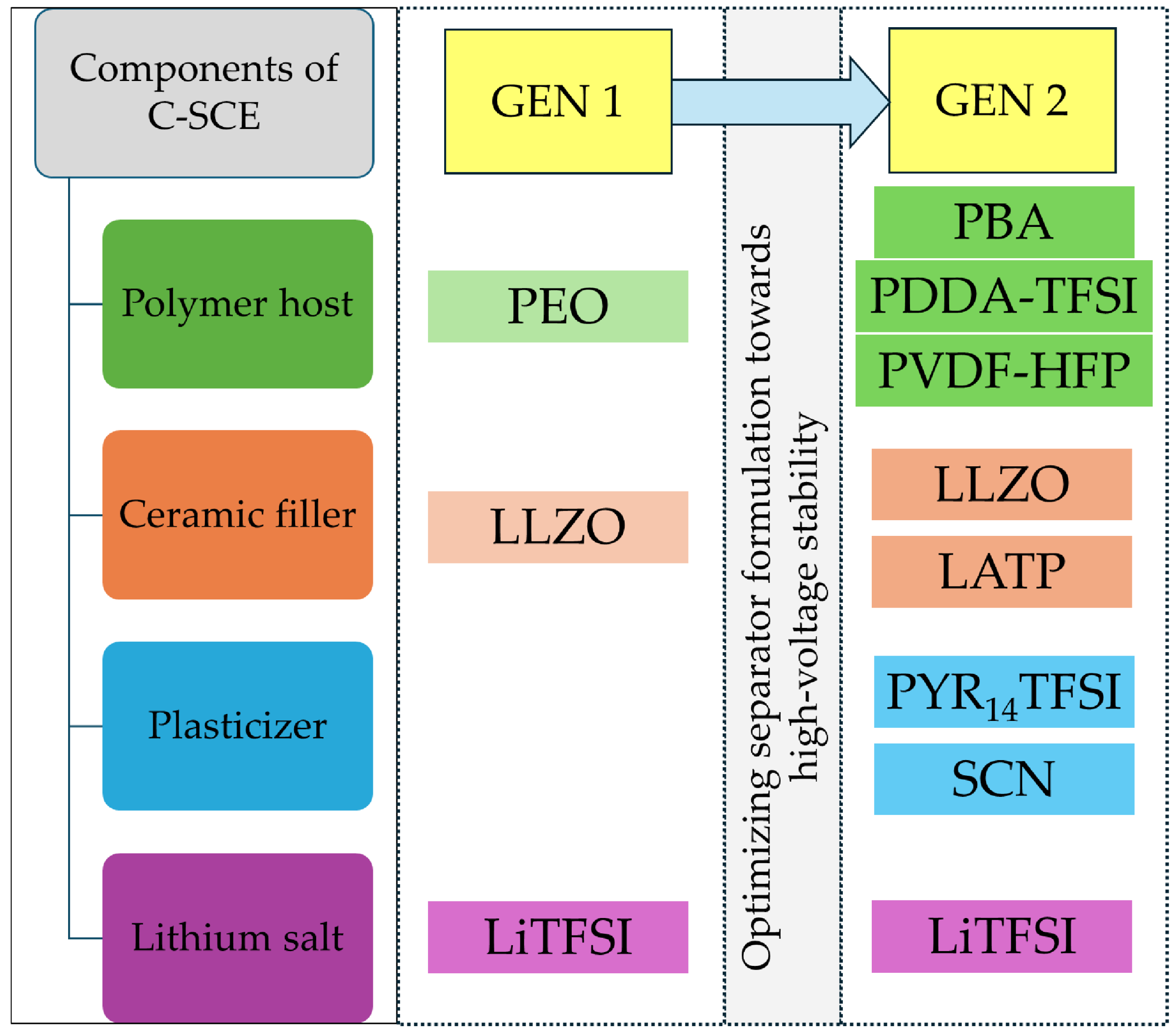
3.1. Optimization of Composite Separator Formulation

The purpose for this work is to address the high-voltage stability issues of LLZO-PEO-LiTFSI-based GEN-1 C-SCEs [32]. To improve the electrochemical performance, the initial attempts made were to replace the PEO-based matrix with a PVDF-HFP-based matrix, maintaining the same content of LLZO in the system. However, it was observed that the prepared C-SCE would be discolored. It has been reported that mixing LLZO with PVDF-HFP causes discoloration of the separator matrix due to dehydrofluorination of PVDF-HFP which could affect the long-term cycling performance in cells [33].
In this work, we elaborated on the fabrication and evaluation of C-SCEs combining different types of Li-ion conductive ceramic powders and polymeric matrices. The filtering and optimization process of various separator compositions was carried out based on their physical stability, microstructure, and ionic conductivity. For optimizing the composition for C-SCEs, various trials were carried out with different polymer-based organic matrices which are listed in Table 1. The preparation methodology for all C-SCE compositions was kept analogous, as described in Section 2.2. However, one of the key differences in the preparation procedure between the fabricated C-SCEs is the usage of different temperatures while carrying out post-processing steps.

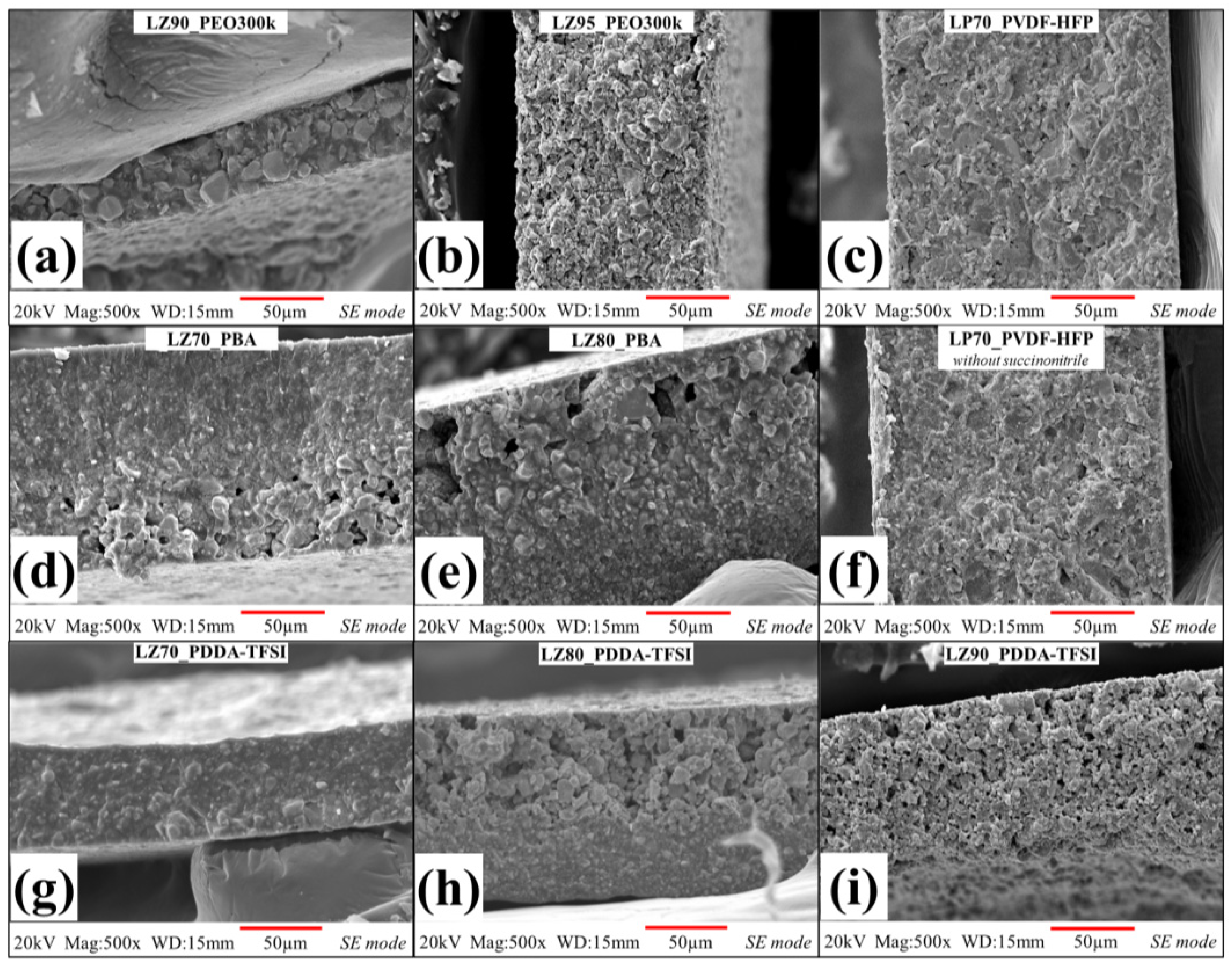
3.1.1. Microstructural Analysis

The homogenized C-SCE slurries consisting of ceramic powders and components of polymeric matrix after mechanical mixing were cast on different substrates, including for PVDF-HFP-based systems and Teflon sheets for PDDA-TFSI and PBA-based systems. The separator membranes were dried at 60 °C in a vacuum oven to remove any remnants of solvents. After drying, separator membranes in the form of disks were subjected to post-processing conditions, as marked in Table 1, to obtain flexible and mechanically stable separators. The hot press step, as part of post-processing of all separators, has been reported [32,34,35] to improve surface morphology, relative density, and the ionic conductivity of SEs. Several trials were carried out to finalize the hot-pressing parameters for the GEN 2 separators. The particle size control for both LLZO and LATP plays an important role in the overall quality of the separators. The sieving of ceramic powders before their addition to the separator slurry plays an important role during casting of membranes with homogenous microstructure. Both LLZO and LATP powders had D90 values of <25 µm (details on size and distribution are available in Supporting Information as Figure S3).
The optimization process of separator formulation for GEN 2 of C-SCEs consisted of a selection of polymer-based matrix and suitable ceramic powders for the matrix. The optimization of the polymeric matrix included the selection of binding polymer, compatible plasticizers, and lithium salt. With PVDF-HFP as the host, two different polymeric matrices were evaluated. The first combination for PVDF-HFP-based separator matrix consisted of PYR14TFSI and SCN as plasticizers and LiTFSI as Li salt. PYR14TFSI [36,37] and SCN [38,39] were chosen due to their reported contributions to improving ionic conductivity, ion mobility, and electrochemical performance in solid polymer electrolyte systems. The second combination consisted of only PYR14TFSI as plasticizing agent and LiTFSI as the Li salt. The two matrix combinations were evaluated to understand the influence of SCN on the overall performance of PVDF-HFP-based C-SCEs. PDDA-TFSI-based separator matrix consisted of PYR14TFSI as plasticizer along with LiTFSI as Li salt. The PBA-based separator matrix consists of LiTFSI as Li salt, without any plasticizers, due to the low molecular weight of PBA compared to that of PVDF-HFP and PDDA-TFSI.
The second part of the material selection process was the choice of ceramic powders in C-SCEs, depending on their processing viability to form stable and self-standing films. For PVDF-HFP-based C-SCEs as result of the dehydrofluorination reaction, LLZO was replaced by LATP. Separators prepared with 80 and 90 wt% of LATP were observed to have problems in forming self-standing separators due a lack of binding in LATP particles which leads to degradation of contact with electrodes and increases interfacial resistance during cycling. In the PDDA-TFSI-based matrix, the selection of LLZO content was more flexible with 70 wt% (LZ70_PDDA-TFSI), 80 wt% (LZ80_PDDA-TFSI), and 90 wt% (LZ90_PDDA-TFSI) of LLZO powders. Similarly for PBA-based matrix, LLZO was selected as the ceramic component with content of 70 wt% (LZ70_PBA) and 80 wt% (LZ80_PBA).
Self-standing and mechanically stable separators were fabricated with thickness between 100–250 µm with both LLZO and LATP as ceramic fillers and different polymer-based matrices. The different material considerations during the optimization process were useful in preparing GEN 2 separators with PVDF-HFP-based, PDDA-TFSI-based, and PBA-based matrices. The prepared C-SCE separators were labeled in Table 1 according to the ceramic content and polymer used in the matrix, e.g., sample LP70_PVDF-HFP contains 70 wt% sieved LATP powder and PVDF-HFP as the polymer in the matrix. The mechanical stability of the separators was highly dependent on the formulations and the individual components in the matrix. For example, during trials for preparing PDDA-TFSI-based separators, it was observed that the addition of SCN to separator matrix had negative effect on the stability of separator film. However, the applications of additional structural stabilization techniques such cross-linking [40,41] and in-situ polymerization [42,43] of the polymeric matrix was out of scope in this work.
A scanning electron microscope (SEM) was used to evaluate the microstructure of the prepared separators. Figure 2 and Figure S3 show the cross-sectional and surface SEM micrographs of all C-SCE separators. Micrographs of the cross-section (Figure 2a,b) and surface (Figure S3a,b) of PEO-based separators [32] were compared with the microstructure and morphology of all other C-SCE separators. The microstructure of both PVDF-HFP- and PDDA-TFSI-based separators with 70 wt% of ceramic powders (LP70_PVDF-HFP, LP70_PVDF-HFP without SCN and LZ70_PDDA-TFSI) are shown in Figure 2c,f,g, respectively. Upon comparison with reference separators, LZ70_PDDA-TFSI in Figure 2g is seen to have a similar microstructure to that of LZ90_PEO300k separator. The increase of polymeric content in the LZ70_PDDA-TFSI matrix helped the improved coating of LLZO particles along with reduction of visible pores in the microstructure. On the other hand, both LP70_PVDF-HFP and LP70_PVDF-HFP without SCN are observed to have microstructures like LZ95_PEO300k. This could be attributed to their increased volume fraction of ceramic particles compared to that of LLZO-based LZ70_PDDA-TFSI separator. Nonetheless, all three separators were seen to have dense microstructure with no visible pores.
The microstructures of other separators with higher ceramic content, LZ80_PDDA-TFSI and LZ90_PDDA-TFSI, were seen to have a lot of macro-sized pores. In PBA-based separators, the cross-sectional microstructure of both LZ70_PBA and LZ80_PBA (Figure 2d,e) showed phase separation between LLZO particles and PBA matrix. When we further analyzed the separation, we observed a gradient in the distribution of polymeric matrix and LLZO particles. In LZ70_PBA and LZ80_PBA, polymer-rich and ceramic-rich regions have been observed to form on either ends of the cross-section. In both separators, large pores were observed in the ceramic-rich part of the separator. In LZ80_PBA, with its higher content of ceramic powders compared to LZ70_PBA, the gradient in ceramic distribution is clearly visible in SEM micrograph in Figure 2e. The surface morphology of LZ80_PBA in Figure S3e depicts large pores and lack of surface integrity stemming from the reduced binding ability of the polymeric matrix. The phase separation in both separators could have happened while drying after casting the separators. During drying of the separators, the polymeric matrix was unable to prevent bigger LLZO particles from settling down due to low molecular weight of PBA and slow evaporation of DMC solvent.

3.1.2. Ionic Conductivity

Electrochemical impedance spectroscopy (EIS) measurements were performed between 80 °C and 30 °C to assess the ionic conductivity of fabricated C-SCEs. The ionic conductivities of GEN 2 separators were compared with PEO-based GEN 1 separators.
Figure 3a shows temperature dependance of ionic conductivity for all separators investigated in this work. The ionic conductivity values of LZ90_PEO300k separator for our previous work was taken as the threshold value for selection of GEN 2 separators for carrying out further characterizations. Since the objective of the study is to evaluate the performance of optimized separators in Li/NMC622 format at coin cell level, conductivity values of all separators are compared at 60 °C and shown in Figure 3b.
Among all the separators being evaluated, the PVDF-HFP-based separators LP70_PVDF-HFP and LP70_PVDF-HFP without SCN exhibited the highest ionic conductivity values. In the PDDA-TFSI-based family, LZ70_PDDA-TFSI demonstrated the highest ionic conductivity among the other three separators. The LZ80_PDDA-TFSI separator showed higher ionic conductivity values compared to that of reference LZ90_PEO300k separator. In PBA-based family, LZ70_PBA exhibited the higher ionic conductivity of 1.2 × 10⁻⁵ S/cm at 60 °C, which is close to that of the LZ90_PEO300k separator. The LZ80_PBA separator exhibited a much lower value of 2.31 × 10⁻⁶ S/cm, compared to that of the GEN 1 LZ90_PEO300k separator.
However, all separators exhibited increasing ionic conductivity values with respective increases in the test temperature up to 80 °C. This increased ionic conductivity values for all separators could be related to the increased ion hopping between polymer chains, increased segmental motion [44]. Out of all the separators, LP70_PVDF-HFP and LP70_PVDF-HFP without SCN are seen to have the highest ionic conductivity at 60 °C of close to 1 mS/cm. This large jump in ionic conductivity compared to other separators could be attributed to the reduction in crystallinity of the PVDF-HFP matrix due to presence of SCN [45] and PYR14TFSI [46] as plasticizers. These two separators have been characterized further in Li/NMC622 cells to understand the influence of SCN on matrix properties for the separators. In PDDA-TFSI-based separators, LZ70_PDDA-TFSI exhibited the highest ionic conductivity at 60 °C with 2.64 × 10⁻⁵ S/cm. LZ80_PDDA-TFSI and LZ90_PDDA-TFSI exhibited ionic conductivity of 1.94 × 10⁻⁵ S/cm and 1 × 10⁻⁶ S/cm, respectively. The decreasing ionic conductivity in PDDA-TFSI-based separator could be attributed to the increasing Tg in par with their ceramic content. The increasing number of pores in the microstructure also contributed to the reduction in ionic conductivity. LZ70_PDDA-TFSI had the fewest pores in the microstructure. LZ90_PDDA-TFSI had presence of multiple pores in the cross-section as well as on the surface. In the case of LZ80_PDDA-TFSI, there were pores seen in the cross-section; however, the surface exhibited a pore-free morphology, as seen in Figure 2h and Figure S3h.
Comparing the different separators in the optimization process, we evaluated their performance based on their mechanical stability, morphology, microstructure, and ionic conductivity. It was seen that PBA-based separators had problems with forming uniform pore-free microstructures along with lower ionic conductivity values than that of GEN 1 the LZ90_PEO300k separator. In PDDA-TFSI-based separators, LZ70_PDDA-TFSI was able to meet all the requirements, having a mechanically stable, pore-free microstructure with ionic conductivity at 60 °C higher than LZ90_PEO300k separator. LZ80_PDDA-TFSI separators demonstrated higher ionic conductivity at 60 °C compared to that of the GEN 1 LZ90_PEO300k separator. However, the GEN 2 separator had a lot of pores in the microstructure which was seen to be detrimental for further electrochemical characterizations. The LZ90_PDDA-TFSI separator has a very porous surface and cross-sectional microstructure with low ionic conductivity value compared to that of LZ90_PEO300k. In PVDF-HFP-based separators, both LP70_PVDF-HFP and LP70_PVDF-HFP without SCN had a dense and pore-free microstructure, with high ionic conductivity values compared to LZ90_PEO300k.
All in all, after the optimization process, LP70_PVDF-HFP and LZ70_PDDA-TFSI were selected for carrying out further galvanostatic cycling in Li/Li and Li/NMC622 cells. Lithium transference number measurements carried out for the optimized LP70_PVDF-HFP and LZ70_PDDA-TFSI separators (found in Figure S5 and Table S1) show values close to that measured for LZ90_PEO300k. In addition, LP70_PVDF-HFP without SCN was tested in Li/NMC622 cells to understand the influence of different components in the matrix on the electrochemical performance, since this separator exhibited similar ionic conductivity values and microstructure to that of LP70_PVDF-HFP.

3.2. Electrochemical Characterization

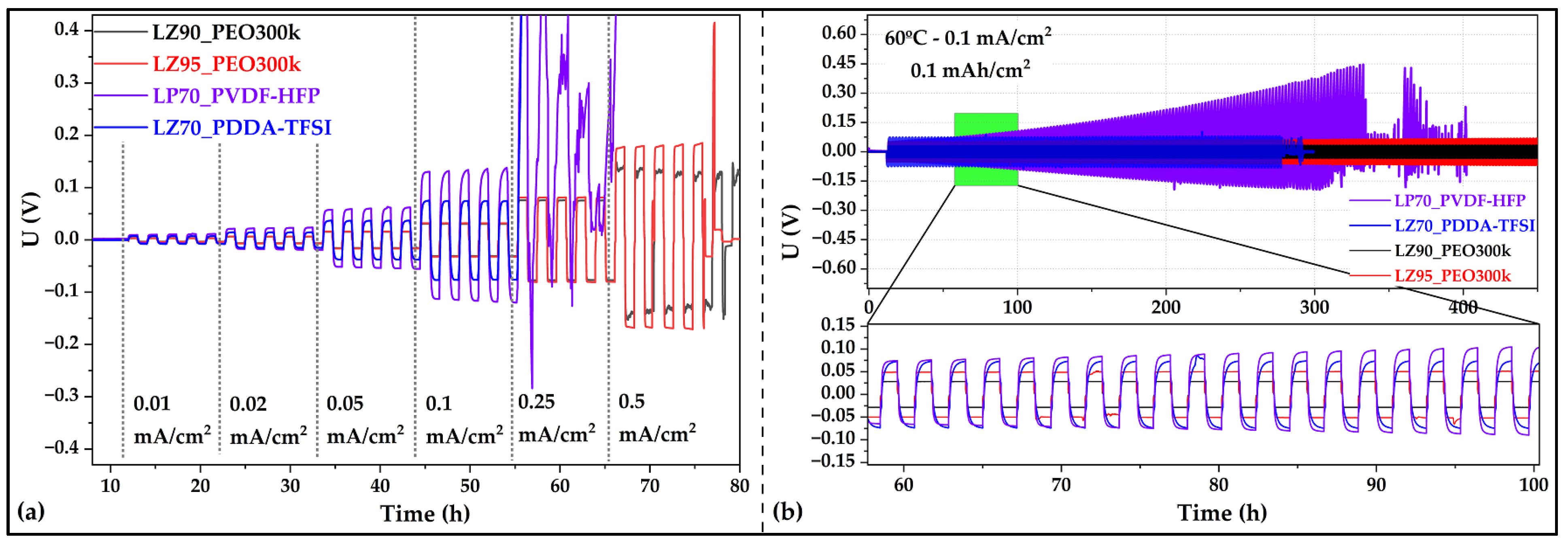
3.2.1. Electrochemical Characterization in Symmetric Li/Li Coin Cells

The long-term electrochemical stability against Li metal and Li dendrites growth resistance for different current densities of the selected separators was assessed in symmetric Li/Li cells. The stripping/plating behavior of Li in cells with the tested separators were assessed both as critical current density (CCD) test [47] and galvanostatic cycling at 0.1 mA/cm2 with an areal capacity of 0.1 mAh/cm2 per half cycle. The electrochemical performance of Li/Li cells with selected GEN 2 separators was compared to that of Li/Li cells with GEN 1 separators with PEO-LLZO-based matrix.
CCD test (voltage vs. time profiles shown in Figure 4a) was performed on cells with selected GEN 2 separators LP70_PVDF-HFP and LZ70_PDDA-TFSI. The current densities (CD) achieved for both separators were assessed against those of LZ90_PEO300k and LZ95_PEO300k. Li/Li cells with both GEN 2 separators exhibited a critical current density of 0.1 mA/cm2, which is below the value achieved by Li/Li cells with LZ90_PEO300k (0.25 mA/cm2) and LZ95_PEO300k (0.5 mA/cm2) [32]. It was observed that in LP70_PVDF-HFP and LZ70_PDDA-TFSI separators after cycling at 0.1 mA/cm2, GEN 2 separators show a sharp increase in the polarization as soon as cycling starts at CD of 0.25 mA/cm2. At this CD step, both separators show failure due to high resistance in LZ70_PDDA-TFSI and soft short circuit due to Li dendrite penetration into separator bulk [47] in LP70_PVDF-HFP. However, both LLZO-PEO-based separators demonstrated lower and stable polarization and were also able to be evaluated at CDs up to 0.5 mA/cm2. This difference in stability against lithium metal could be attributed to better wettability [48] of PEO compared to that of PDDA-TFSI and PVDF-HFP, as well as possible SEI formation on lithium metal.
Further confirmation of the achieved CDs for LP70_PVDF-HFP and LZ70_PDDA-TFSI were carried out in long-term galvanostatic cycling in symmetric Li/Li cells and shown in Figure 4b. Stable voltage over 1000 h were observed in Li/Li cells with LZ90_PEO300k and LZ95_PEO300k separators [32]. In Li/Li cells with LZ70_PDDA-TFSI, symmetric and stable cycling profile with higher voltage values were observed. But cycling in Li/Li cells with LZ70_PDDA-TFSI could only be demonstrated for up to 290 h, after which the cell underwent a short circuit. Comparing the cycling profiles of LLZO-PEO- and LLZO-PDDA-TFSI-based separators (Figure 4b (inset)), it was observed that PEO-based system had a flat symmetric voltage profile, indicating a more stable SEI and more unform Li stripping/plating. On the other hand, the PDDA-TFSI-based system was seen to have a slopping cycling profile, which indicates the increase (logarithmic in this case) could be due to evolution in SEI formation. The slopping profile shape of the polarization can also be seen in the case PVDF-HFP-based system. In Li/Li cells with the PVDF-HFP separator, the cycling started with a symmetric voltage; however, the long-term cycling of the Li/Li cell was observed to have an asymmetric profile. This behavior was seen in tandem with increasing polarization leading ultimately to failure, which was attributed to the different composition of the separator surfaces. The origin of formation of two different sides of the separator is related to the separator preparation process when the top surface is in contact with air and the bottom surface is in contact with the glass substrate causing segregation of the LATP ceramic filler. To understand this behavior further, Li/Li cells with single layer and double layer of the separator were prepared. The cell with double-layered separator was fabricated by hot-pressing two discs of separator with the same surfaces in contact with the Li metal. Figure S6 depicts the voltage vs. time profiles for both sets of Li/Li cells, which confirms the presence of symmetric behavior when double-layered separator with two similar surfaces were put in contact with Li metal. However, this also presented another issue of increasing instability of the double-layered separator in Li/Li cell with faster failure compared to that of single-layered separator probably. This could be attributed to the increased amount of LATP particles in the double-layered separator and the presence of an additional interface between the separators. Huang and coworkers [49] demonstrated that coating and insulating of LATP particles increases the cycling stability of Li/Li cell; however, it was still observed to have increasing polarization over long-term cycling.

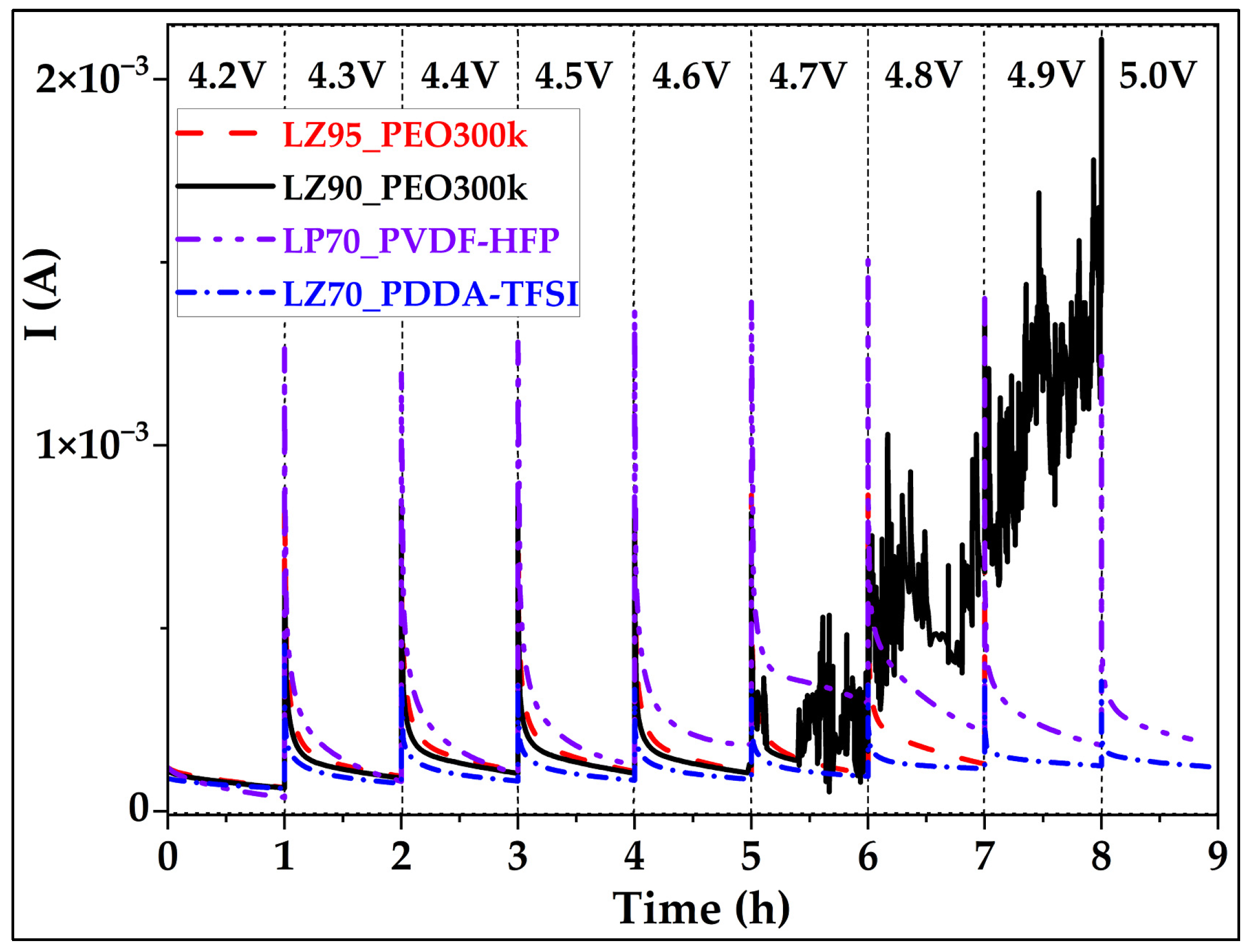
3.2.2. Electrochemical Characterization in Li/NMC622 Coin Cells

The electro-oxidative stability limit of the separators was evaluated using an electrochemical float test [50] method, taking into account some of the reported limitations of linear sweep voltammetry (LSV). Even though the application of LSV is straightforward, the analysis and explanation of the dataset is still ambiguous and usually overestimates the electrochemical stability limit [51] due to various reported reasons [52,53]. During the float test, charging voltage was kept constant/hold (float) for 1 h and during this time the current was monitored to detect electro-oxidation of the electrolytes. The stability limit for separators was observed from Figure 5 to be 5.0 V for both LP70_PVDF-HFP and LZ70_PDDA-TFSI, and 4.6 V and 4.8 V for LZ90_PEO300k and LZ95_PEO300k [32], respectively. These results demonstrated that the replacement of polymeric matrices from PEO to PVDF-HFP or PDDA-TFSI-based systems improved the overall oxidative stability of ceramic-rich separators.
To further evaluate the electrochemical performance of LP70_PVDF-HFP and LZ70_PDDA-TFSI, Li/NMC622-based cells were tested at different discharge C-rates and for long-term cycling at 0.05C/0.1C rate. All the tests were carried out at 60 °C and within cycling voltage-window of 3.0–4.3 V. All results for GEN 2 separators were compared with the performance of LZ90_PEO300k in Li/NMC622 cells to assess the effectiveness of changes in polymeric matrix on the galvanostatic cycling performance.
During discharge rate testing, Li/NMC622 cells with the LP70_PVDF-HFP separator demonstrated the best performance among the Li/NMC622 cells with the three separators. The discharge capacities at the different C-rates applied in a Li/NMC622 cell with LP70_PVDF-HFP as follows 0.1C (188.6 mAh/g), 0.2C (169.2 mAh/g), 0.33C (148.1 mAh/g), 0.5C (125.3 mAh/g), 1C (22.6 mAh/g), and 2C (10.0 mAh/g). The discharge curves for Li/NMC622 cell with LP70_PVDF-HFP in Figure 6a depict the evolution of discharge capacity over the different discharge C-rates applied during the test. Even at a 0.5C discharge rate, it was seen that the cells were able to retain 66% only of the initial discharge capacity at 0.1C. But there is a sudden drop in the discharge capacities for C-rates of 1C and 2C, as seen in Figure 6e. On the other hand, in the case of Li/NMC622 cells with LLZO-based separators of LZ70_PDDA-TFSI and LZ90_PEO300k, a rapid decrease was displayed in the discharge capacities with increasing discharge C-rates applied during the test. In cells with LZ70_PDDA-TFSI and LZ90_PEO300k, relevant discharge capacities were only observed at 0.1C. The rapid decreasing trend of discharge capacities can be seen in voltage versus capacity curves for the Li/NMC622 cells with both LZ90_PEO300k and LZ70_PDDA-TFSI separators (Figure 6b,c), respectively. For the Li/NMC622 cell with LZ70_PDDA-TFSI, the discharge capacities for all discharge C-rates are as follows: 0.1C (147.3 mAh/g), 0.2C (19.5 mAh/g), 0.33C (11.6 mAh/g), 0.5C (7.5 mAh/g), 1C (3.1 mAh/g), and 2C (0.8 mAh/g). For the Li/NMC622 cell with LZ90_PEO300k, the discharge capacities for all discharge C-rates—0.1C (161.5 mAh/g), 0.2C (23.6 mAh/g), 0.33C (9.7 mAh/g), 0.5C (8.1 mAh/g), 1C (6.0 mAh/g), and 2C (0.7 mAh/g). However, the discharge capacities in recovery cycles for all cells with GEN 2 separators were seen in Figure 6d to increase to relevant values of greater than 150 mAh/g. This demonstrates that Li/NMC622 cells with PVDF-HFP and PDDA-TFSI-based separators do not cause any noticeable damage to the systems at higher discharge C-rates, but the low discharge capacity is mainly due to kinetic limitations which should be further investigated by SS-NMR, GITT, and other advanced methods. Similar behavior in Li/NMC622 cell with PEO-based composite electrolyte was also observed and reported by López-Aranguren et al. [54]. A summary of discharge capacities for all discharge C-rates shown in Figure 6e showcases the enhanced performance of LP70_PVDF-HFP-based cells comparing to LZ70_PDDA-TFSI and LZ90_PEO300k ones, which can in part be attributed to the higher ionic conductivity of LP70_PVDF-HFP and lower interface resistance.
After the discharge C-rate performance test, 0.1C as discharge rate was analyzed to be the most suitable for comparing long-term galvanostatic cycling behavior in Li/NMC622 cells for both GEN 1 and GEN 2 separators. Figure 7a,b demonstrate the long-term cyclability of solid-state Li/NMC622 cells with LZ90_PEO300k, LP70_PVDF-HFP, and LZ70_PDDA-TFSI separators. The average initial discharge capacities for cells with different separators are as follows: LZ90_PEO300k—172.7 mAh/g, LP70_PVDF-HFP—189.1 mAh/g, and LZ70_PDDA-TFSI—145.2 mAh/g, respectively. The capacity fade of cells with LZ90_PEO300k is very fast as reported earlier [32], and as seen in the voltage versus capacity plot in Figure 7d. In the case of Li/NMC622 cells with GEN 2 separators, we observed a much slower capacity fade compared to that of cells with LZ90_PEO300k. LP70_PVDF-HFP-based Li/NMC622 cells exhibited the highest values in both discharge capacity and coulombic efficiencies with LZ90_PEO300k-based cells following closely behind. The cells with LZ70_PDDA-TFSI showed lower initial discharge capacity, but over next few cycles the discharge capacity and the Coulombic efficiency values increased to the maximum values of 155.3 mAh/g in the 3rd cycle. The slow increase in the discharge capacity for cells with LZ70_PDDA-TFSI could be attributed to the need for activation of the “Li/separator/NMC622” stack.
Comparing the cyclability of Li/NMC622 cells with GEN 2 separators as shown in Table 2, in cells with LP70_PVDF-HFP, the discharge capacities were higher compared to cells assembled with PDDA-TFSI-based separator. On the other hand, the capacity retention over the cycling period was observed to be better in the LZ70_PDDA-TFSI-based cell, which was seen in Figure 7a and the voltage versus capacity profiles in Figure 7e. However, in Li/NMC622 cells with LP70_PVDF-HFP, by the 22nd cycle (voltage versus capacity profiles in Figure 7f), there were problems with excessive charge capacity (>220 mAh/g), observed due to soft short-circuits during charging. With the start of soft short circuits, both discharge capacity and coulombic efficiency values decreased rapidly. The capacity fade in the cells is more severe as the number of cycles increases. By the 30th cycle, the capacities have declined below that of cell with LZ70_PDDA-TFSI. This difference in the stability of the two GEN 2 separators could be attributed to the polymers themselves and possible dehydrofluorination of PVDF-HFP polymer in contact with Li metal [55,56]. This can be observed in cycling profiles of symmetric Li/Li cells (Figure 4b), where the polarization stayed stable in the case of the LZ70_PDDA-TFSI-based cell, but it was seen to be increasing in the case of the PVDF-HFP-based cell. The slow capacity fade in cells with LZ70_PDDA-TFSI and LP70_PVDF-HFP could be also seen as the effect of PEO-based catholyte in the composite cathode.
The average voltages of the Li/NMC622 cells with all three separators were analyzed using PROTEO™ Data Analytics V1 (CIDETEC) and shown in Figure 7c. In the graph, there are indications towards degradation in the Li/NMC622 cells with LZ90_PEO300k and LP70_PVDF-HFP due to the increasing difference between the average voltages of charge and discharge. However, in the Li/NMC622 cells with LZ70_PDDA-TFSI, it was observed that the difference between average voltage values was large compared to other systems, which could be due to the higher resistance of the “Li/separator/NMC622” stack and may corroborate the better stability of cells during long-term cycling.
Additionally, to understand the influence of various matrix components, PVDF-HFP-based separators were tested in Li/NMC622 cells, including the LP70_PVDF-HFP separator without SCN. Figure S7 compares the cycling performance for Li/NMC622 cells with both GEN 2 PVDF-HFP-based C-SCEs. The Li/NMC622 cells with both separators demonstrate relevant initial discharge capacities. Figure S7d,e illustrate rapid capacity decay in the voltage versus time plots for Li/NMC622 cells with both separators. However, it was observed that from the 2nd cycle onwards that the discharge capacity for Li/NMC622 cells with LP70_PVDF-HFP without SCN decreased very rapidly to less than 50% of the initial discharge capacity. One of the probable reasons for deviation in the cycling performance could be related to the ability of SCN (presented in LP70_PVDF-HFP matrix) to separate charges in the electrolyte and the rotational motion of SCN molecules. Both of which would aid in the better transport of ions during cycling [46].
Figure 7g–i depict the incremental capacity curves (dQ/dV) for Li/NMC622 cells with LZ90_PEO300k, LP70_PVDF-HFP, and LZ70_PDDA-TFSI separators, respectively. The dQ/dV analysis has been carried out on the 1st (a—charge and b—discharge) and 10th (a’—charge and b’—discharge) cycle of Li/NMC622 cells. Comparing all dQ/dV curves in the charging process, in the 1st cycle for Li/NMC622 cell with LP70_PVDF-HFP, a more pronounced peak (marked in red circle) with increased intensity was observed. It has been reported by S. Zhang and R. Jung et al. [57,58] that the first peak is usually related to hexagonal (H1) to monoclinic (M) transformation, which could be split in some cases, where first peak represents Ni3+/Ni4+ oxidation and second peak is attributed to Co3+/Co4+ oxidation. The splitting of H1 to M peak is observed in all Li/NMC622-based systems; however, in Li/NMC622 cells with LZ90_PEO300k and LZ70_PDDA-TFSI separators, the first part of the split peak has very low intensity. The increased intensity seen for the pronounced first peak (marked with red circle in Figure 7i) corresponds to the higher capacities observed during charge in Li/NMC622 cell with LP70_PVDF-HFP and could be attributed to decreasing “separator/cathode” interface resistance. On comparing charging process peaks for cells with LLZO-based separators, the reduction in the peak intensities over both cycles is more prominent in the case of cells with LZ90_PEO300k. This variance in the peak intensities for the 10th cycle between the two separators demonstrates the large capacity fade in Li/NMC622 cell with LZ90_PEO300k, which corroborates the differences in discharge capacities as seen in Table 2. No further phase transition peaks were observed in NMC622 material due to the charging voltage not reaching 4.6 V [57]. The broadening and shift of discharge process peaks during the cycling could be seen due to an increase in overall cell resistance [59].

3.3. Comparitive Analysis

The work carried out here is part of an initial attempt at optimization of ceramic-rich separators aimed at being used in lithium metal-based high-voltage solid-state batteries. From our previous work [32], the key message about PEO-based ceramic-rich separators was about the requirement for modifying the polymer host in the matrix for pairing with high-voltage cathode materials. However, it has been observed that the change in the formulation of a polymer-based matrix is not to simply replace PEO with an HV-stable polymer such as PDDA-TFSI or PVDF-HFP. Therefore, in this work, we were focused on optimizing the matrix in GEN 2 ceramic-rich composite separators (C-SCEs) to improve their applicability in HV solid-state batteries with Li metal anode. The optimization of the separator matrix was done in two parts, with the first part concerning material selection and preparation and the second part concerning the testing of the separators. All GEN 2 separators were compared with LLZO-PEO-LiTFSI-based reference separators during the optimization trials.
The first part of the optimization process consisted of selecting the components for each matrix and their successful fabrication after modifying the post-processing parameters. The investigated separators were tested for their film-forming ability, surface morphology, cross-sectional microstructure, and ionic conductivity at different temperatures. All GEN 2 separators have been prepared via a facile process which can be easily scaled up to larger batch sizes. It is important to utilize high-energy mixing solutions to compensate for problems with agglomeration of ceramic particles. The processing of different separators was highly dependent on the molecular weight of the used polymers, which was seen from the lack of film formation for LZ70_PBA and LZ80_PBA. An important parameter to be monitored is the viscosity of separator slurry, which helps in achieving desired thicknesses and prevent sedimentation of ceramic particles. The selection of separators for the second part has been done based on physical–chemical property evaluations and ionic conductivity measurements.
In the second part, selected GEN 2 separators have been evaluated for their stability against lithium metal and in high-voltage Li/NMC622 cells. In Li/Li cells with LZ70_PDDA-TFSI and LP70_PVDF-HFP, both GEN 2 separators were only able to endure CCD of 0.1 mA/cm2 compared to that of 0.25 mA/cm2 [32] in LLZO-PEO-based GEN 1 separators. During long-term cycling of Li/Li cells with GEN 2 separators, relatively poor cyclability has been demonstrated, with “Li/LZ70_PDDA-TFSI/Li” being stable up to 300 h and “Li/LP70_PVDF-HFP/Li” being stable up to 350 h. Both GEN 2 separators exhibited relatively poor stability with lithium metal compared to LZ90_PEO300k, which remained stable, cycling for more than 800 h with a stable polarization. Li/Li cells with LZ70_PDDA-TFSI demonstrated stable and symmetric polarization compared to unstable and asymmetric polarization in Li/Li cells with LP70_PVDF-HFP during long-term cycling.
However, when Li/NMC622 cells with GEN 2 separators were evaluated, it was seen that the roles were reversed, with Li/NMC622 cells with GEN 2 separators proving to be more stable compared to those of Li/NMC622 cells with LZ90_PEO300k during long-term galvanostatic cycling. Comparing the performance of the selected GEN 2 separators, it was seen that LP70_PVDF-HFP demonstrated good discharge C-rate performance with relevant discharge capacities up to 0.5C compared to that of 0.1C for LZ70_PDDA-TFSI. On the other hand, LZ70_PDDA-TFSI based cells exhibited stable cyclability with better capacity retention of the two GEN 2 separators over 50 cycles. Further advanced characterization required to shed light on the potential degradation mechanisms for each of the separator systems will be performed as part of future work.
Figure 8 summaries the results from various indicators evaluated during this study. It could be observed that the PEO-based GEN 1 separator shows good performances in factors which were directly affected by contact with Li metal, having a good lithophilic behavior. On the other hand, GEN 2 separators exhibit better performance in indicators which directly deal with high-voltage solid-state batteries. Thus, designing and optimizing ceramic-rich composite separators is not straight-forward and requires more inputs to improve the performance, especially for the stability with lithium metal and a high-voltage stable cathode.

4. Conclusions

To summarize, this work is focused on the optimization and fabrication of ceramic-rich composite separators (GEN 2) to address high-voltage instability of a polymeric matrix demonstrated by PEO-based composite separators. The composite separators were prepared using facile solution-casting method to study the influence of different matrix components and compositions on the electrochemical stability of Li/NMC622 cells with ceramic-rich composite separators.
The investigated GEN 2 composite separators with different ceramic contents and polymer matrices (PVDF-HFP, PDDA-TFSI, and PBA) have been explored in this study to assess their effect on the mechanical stability, microstructure, and high-voltage stability of the separators. PBA-based ceramic-rich composite separators have been discarded at an early stage due to poor mechanical properties and low ionic conductivity. Other separators based on 80 wt% and 90 wt% LLZO in PDDA-TFSI-based matrix have been also rejected due to low ionic conductivity and poor mechanical properties.
Therefore, separators with 70 wt% of the ceramic content in PVDF, and PDDA-TFSI polymer-based matrices were optimized and evaluated further. The LP70_PVDF-HFP separator was seen to have the highest ionic conductivity at 60 °C, followed by the LZ70_PDDA-TFSI and LZ90_PEO300k separators. Both LP70_PVDF-HFP and LZ70_PDDA-TFSI separators with dense microstructure were evaluated for their stability against lithium metal and high-voltage Li/NMC622 cells.
The differences between the PEO-based GEN 1 and PDDA-TFSI and PVDF-HFP-based GEN 2 separators are very noticeable during the electrochemical characterizations in both Li/Li and Li/NMC622 cells. In Li/Li cells testing the stability against Li metal, cells with PEO-based GEN 1 separators had superior performance compared to cells with both GEN 2 separators. The superior performance of Li/Li cells with GEN 1 separators was true in both cases of critical current density and long-term cycling tests. Contrary to the performance of Li/Li cells, Li/NMC622 cells with both GEN 2 separators showcased better performance during long-term cycling compared to the PEO-based GEN 1 separator. Li/NMC622 cells with LP70_PVDF-HFP and LZ70_PDDA-TFSI have been observed to have higher discharge capacity retention, as well as higher coulombic efficiency, signifying improved electrochemical stability of the high-voltage stable polymers and more reversible systems during cycling.
Li/NMC622 cells with LP70_PVDF-HFP and LZ70_PDDA-TFSI exhibited better performances in discharge C-rate performance and long-term cycling, respectively. Therefore, it was seen that when changing from a lithophilic polymer such as PEO in the matrix, some sacrifices need to be made to improve performance at high voltage cycling conditions for the solid-state batteries. Nevertheless, despite improvement in high-voltage stability during cycling after changing the polymer type in the matrix, the degradation observed is significant and needs to be further characterized for better understanding.
As part of future work, it is recommended that the GEN 2 separators be tested in cells with a composite cathode having a high-voltage stable catholyte to compare the changes in cyclability and capacity retention with the replacement of the PEO-based catholyte. GEN 2 separators in combination with high-voltage stable cathodes would also be evaluated for cycling performance at a lower operating temperature of 25 °C.

Supplementary Materials

The following supporting information can be downloaded at: https://www.mdpi.com/article/10.3390/batteries11020042/s1, Figure S1 Scheme of LATP synthesis process via solution assisted solid-state reaction route; Figure S2 XRD diffractograms of (a) cubic—LLZO and (b) rhombohedral LATP powder with (Batteries 11 00042 i001) marking additional orthorhombic phase and (Batteries 11 00042 i002) marking additional marking additional LiTiPO5 phase; SEM micrographs for (c) LLZO powder particles and (d) LATP powder particles. Powder particle size distribution graph for (e) LLZO and (f) LATP; Figure S3 Cross-sectional SEM images of fabricated C-SCEs comparing microstructures of different polymeric matrix groups, starting from PEO-matrix-based separators [2]: (a) LZ90_PEO300k- and (b) LZ95_PEO300k-, PVDF-HFP-matrix-based separators (c) LP70_PVDF-HFP and (f) LP70_PVDF-HFP without SN, PBA-matrix-based separators (d) LZ70_PBA and (e) LZ80_PBA- and PDDA-TFSI-matrix-based separators (g) LZ70_PDDA-TFSI (h) LZ80_PDDA-TFSI and (i) LZ90_PDDA-TFSI; Figure S4 TGA thermographs for (a) LZ70_PDDA-TFSI and (b) LP70_PVDF-HFP; Figure S5 Original and fitted EIS spectra for (a) Li/LZ70_PDDA-TFSI/Li and (d) Li/ LP70_PVDF-HFP /Li cell before and after polarization; Inset- Chronoamperometry profile (I vs. time) of (b) Li/LZ70_PDDA-TFSI/Li and (e) Li/ LP70_PVDF-HFP /Li symmetric cell; (c) and (f) Equivalent circuit used to fit the (before and after polarization) impedance profiles for transference number.; Figure S6 Voltage versus time profiles for long-term galvanostatic cycling of Li/Li cells with LP70_PVDF-HFP. Cycling conditions: current density 0.1 mA/cm2, half cycle step of 1 h, 60 °C.; Figure S7 Discharge capacity and (b) coulombic efficiencies efficiency and (c) average voltage of both charge and discharge step of Li/NMC622 cells with LP70_PVDF-HFP and LP70_PVDF-HFP without SCN. Voltage versus capacity curves for Li/NMC622 cells with GEN 2 separators after long-term cycling (d) LP70_PVDF-HFP without SCN and (e) LP70_PVDF-HFP. All comparisons were made after cycling for 20 cycles. dQ/dV versus voltage curves of the 1st and 10th cycles for Li/NMC622 cells with (g) LP70_PVDF-HFP without SCN, (h) LP70_PVDF-HFP; Table S1 Transference number for GEN 2 separators [14,32,60,61,62,63].

Author Contributions

Conceptualization, K.V., D.F.-R. and A.K.; methodology, K.V., M.F., D.F.-R. and A.K.; validation, K.V. and A.K.; formal analysis, K.V. and A.K.; investigation, K.V.; resources, M.F., D.F.-R., I.U. and A.K.; data curation, K.V. and A.K.; writing—original draft preparation, K.V.; writing—review and editing, K.V., M.F., D.F.-R., I.U. and A.K.; visualization, D.F.-R. and A.K.; supervision, D.F.-R. and A.K.; project administration, D.F.-R. and A.K.; funding acquisition, D.F.-R., I.U. and A.K. All authors have read and agreed to the published version of the manuscript.

Funding

Funding from Fundación CIDETEC, DESTINY COFUND PhD Programme under Marie Sklodowska-Curie grant (G.A. No 945357), and German “Federal Ministry of Education and Research” (BMBF) under grant numbers 13XP0434A (FestBatt 2—Oxid) and 13XP0428A (FestBatt2—Hybride).

Data Availability Statement

The data that support the findings of this study are available from the corresponding author upon reasonable request.

Acknowledgments

K.V. acknowledges the funding from the DESTINY COFUND PhD Programme which has received funding from the European Union’s Horizon 2020 research and innovation programme under the Marie Sklodowska-Curie (grant agreement No 945357) and Fundación CIDETEC. Financial support from the German “Federal Ministry of Education and Research” (BMBF) under grant numbers 13XP0434A (FestBatt 2—Oxid) and 13XP0428A (FestBatt2—Hybride) is gratefully acknowledged. The authors also gratefully acknowledge Grit Häuschen and Philipp Hecker from Forschungszentrum Jülich GmbH for help with the synthesis of LLZO and LATP powders used in this work.

Conflicts of Interest

The authors declare no conflicts of interest.

References

  1. Ozawa, K. Lithium-ion rechargeable batteries with LiCoO2 and carbon electrodes: The LiCoO2/C system. Solid. State Ion. 1994, 69, 212–221. [Google Scholar] [CrossRef]
  2. Eftekhari, A. Lithium Batteries for Electric Vehicles: From Economy to Research Strategy. ACS Sustain. Chem. Eng. 2019, 7, 5602–5613. [Google Scholar] [CrossRef]
  3. Lin, Z.; Liu, T.; Ai, X.; Liang, C. Aligning academia and industry for unified battery performance metrics. Nat. Commun. 2018, 9, 5262. [Google Scholar] [CrossRef] [PubMed]
  4. Takada, K. Progress and prospective of solid-state lithium batteries. Acta Mater. 2013, 61, 759–770. [Google Scholar] [CrossRef]
  5. Hu, Y.-S. Batteries: Getting solid. Nat. Energy 2016, 1, 16042. [Google Scholar] [CrossRef]
  6. Xie, Z.; Wu, Z.; An, X.; Yue, X.; Wang, J.; Abudula, A.; Guan, G. Anode-free rechargeable lithium metal batteries: Progress and prospects. Energy Storage Mater. 2020, 32, 386–401. [Google Scholar] [CrossRef]
  7. Salvatierra, R.V.; Chen, W.; Tour, J.M. What Can be Expected from “Anode-Free” Lithium Metal Batteries? Adv. Energy Sustain. Res. 2021, 2, 2000110. [Google Scholar] [CrossRef]
  8. Yu, T.; Li, G.; Duan, Y.; Wu, Y.; Zhang, T.; Zhao, X.; Luo, M.; Liu, Y. The research and industrialization progress and prospects of sodium ion battery. J. Alloys Compd. 2023, 958, 170486. [Google Scholar] [CrossRef]
  9. Wang, H.; Ozkan, C.S.; Zhu, H.; Li, X. Advances in solid-state batteries: Materials, interfaces, characterizations, and devices. MRS Bull. 2023, 48, 1221–1229. [Google Scholar] [CrossRef]
  10. Schmaltz, T.; Hartmann, F.; Wicke, T.; Weymann, L.; Neef, C.; Janek, J. A Roadmap for Solid-State Batteries. Adv. Energy Mater. 2023, 13, 2301886. [Google Scholar] [CrossRef]
  11. Bates, A.M.; Preger, Y.; Torres-Castro, L.; Harrison, K.L.; Harris, S.J.; Hewson, J. Are solid-state batteries safer than lithium-ion batteries? Joule 2022, 6, 742–755. [Google Scholar] [CrossRef]
  12. Guo, Y.; Wu, S.; He, Y.-B.; Kang, F.; Chen, L.; Li, H.; Yang, Q.-H. Solid-state lithium batteries: Safety and prospects. eScience 2022, 2, 138–163. [Google Scholar] [CrossRef]
  13. Wang, L.; Li, J.; Lu, G.; Li, W.; Tao, Q.; Shi, C.; Jin, H.; Chen, G.; Wang, S. Fundamentals of Electrolytes for Solid-State Batteries: Challenges and Perspectives. Front. Mater. 2020, 7, 111. [Google Scholar] [CrossRef]
  14. Murugan, R.; Thangadurai, V.; Weppner, W. Fast Lithium Ion Conduction in Garnet-Type Li7La3Zr2O12. Angew. Chem. Int. Ed. 2007, 46, 7778–7781. [Google Scholar] [CrossRef]
  15. Öksüzoğlu, F.; Ateş, Ş.; Özkendir, O.M.; Çelik, G.; Eker, Y.R.; Baveghar, H. Structure and ionic conductivity of NASICON-type LATP solid electrolyte synthesized by the solid-state method. Ceram. Int. 2024, 50, 31435–31441. [Google Scholar] [CrossRef]
  16. Liu, S.; Zhou, L.; Han, J.; Wen, K.; Guan, S.; Xue, C.; Zhang, Z.; Xu, B.; Lin, Y.; Shen, Y.; et al. Super Long-Cycling All-Solid-State Battery with Thin Li6PS5Cl-Based Electrolyte. Adv. Energy Mater. 2022, 12, 2200660. [Google Scholar] [CrossRef]
  17. Yang, X.; Gao, X.; Jiang, M.; Luo, J.; Yan, J.; Fu, J.; Duan, H.; Zhao, S.; Tang, Y.; Yang, R.; et al. Grain Boundary Electronic Insulation for High-Performance All-Solid-State Lithium Batteries. Angew. Chem. Int. Ed. 2023, 62, e202215680. [Google Scholar] [CrossRef]
  18. Li, Z.; Fu, J.; Zhou, X.; Gui, S.; Wei, L.; Yang, H.; Li, H.; Guo, X. Ionic Conduction in Polymer-Based Solid Electrolytes. Adv. Sci. 2023, 10, 2201718. [Google Scholar] [CrossRef]
  19. Bachman, J.C.; Muy, S.; Grimaud, A.; Chang, H.-H.; Pour, N.; Lux, S.F.; Paschos, O.; Maglia, F.; Lupart, S.; Lamp, P.; et al. Inorganic Solid-State Electrolytes for Lithium Batteries: Mechanisms and Properties Governing Ion Conduction. Chem. Rev. 2016, 116, 140–162. [Google Scholar] [CrossRef]
  20. Yang, X.; Jiang, M.; Gao, X.; Bao, D.; Sun, Q.; Holmes, N.; Duan, H.; Mukherjee, S.; Adair, K.; Zhao, C.; et al. Determining the limiting factor of the electrochemical stability window for PEO-based solid polymer electrolytes: Main chain or terminal -OH group? Energy Environ. Sci. 2020, 13, 1318–1325. [Google Scholar] [CrossRef]
  21. Yang, X.; Yin, Q.; Wang, C.; Doyle-Davis, K.; Sun, X.; Li, X. Towards practically accessible high-voltage solid-state lithium batteries: From fundamental understanding to engineering design. Prog. Progress. Mater. Sci. 2023, 140, 101193. [Google Scholar] [CrossRef]
  22. Thompson, T.; Yu, S.; Williams, L.; Schmidt, R.D.; Garcia-Mendez, R.; Wolfenstine, J.; Allen, J.L.; Kioupakis, E.; Siegel, D.J.; Sakamoto, J. Electrochemical Window of the Li-Ion Solid Electrolyte Li7La3Zr2O12. ACS Energy Lett. 2017, 2, 462–468. [Google Scholar] [CrossRef]
  23. Xiao, W.; Wang, J.; Fan, L.; Zhang, J.; Li, X. Recent advances in Li1+xAlxTi2−x(PO4)3 solid-state electrolyte for safe lithium batteries. Energy Storage Mater. 2019, 19, 379–400. [Google Scholar] [CrossRef]
  24. Jie, J.; Liu, Y.; Cong, L.; Zhang, B.; Lu, W.; Zhang, X.; Liu, J.; Xie, H.; Sun, L. High-performance PVDF-HFP based gel polymer electrolyte with a safe solvent in Li metal polymer battery. J. Energy Chem. 2020, 49, 80–88. [Google Scholar] [CrossRef]
  25. Seo, Y.; Jung, Y.-C.; Park, M.-S.; Kim, D.-W. Solid polymer electrolyte supported by porous polymer membrane for all-solid-state lithium batteries. J. Membr. Sci. 2020, 603, 117995. [Google Scholar] [CrossRef]
  26. Fu, C.; Homann, G.; Grissa, R.; Rentsch, D.; Zhao, W.; Gouveia, T.; Falgayrat, A.; Lin, R.; Fantini, S.; Battaglia, C. A Polymerized-Ionic-Liquid-Based Polymer Electrolyte with High Oxidative Stability for 4 and 5 V Class Solid-State Lithium Metal Batteries. Adv. Energy Mater. 2022, 12, 2200412. [Google Scholar] [CrossRef]
  27. Lucia, M.; Akiko, T.; Graziano Di, D.; Henry, A.; Maria Assunta, N.; Stefano, P. Quasi-solid-state electrolytes—Strategy towards stabilising Li|inorganic solid electrolyte interfaces in solid-state Li metal batteries. Energy Mater. 2023, 3, 300019. [Google Scholar] [CrossRef]
  28. Villacis-Segovia, C.; Del Olmo, R.; Olmedo Martínez, J.L.; ÓDell, L.A.; Fernández, M.; Mecerreyes, D.; Kvasha, A.; Villaluenga, I. Understanding Li6.24La3Zr2Al0.24O11.98 effect on poly(ionic liquid)-based electrolytes for high voltage solid-state lithium batteries working at room temperature. Chem. Eng. J. 2024, 500, 156221. [Google Scholar] [CrossRef]
  29. Pan, Q.; Barbash, D.; Smith, D.M.; Qi, H.; Gleeson, S.E.; Li, C.Y. Correlating Electrode–Electrolyte Interface and Battery Performance in Hybrid Solid Polymer Electrolyte-Based Lithium Metal Batteries. Adv. Energy Mater. 2017, 7, 1701231. [Google Scholar] [CrossRef]
  30. Wu, S.; Wang, C.; Li, S.; Weng, J. Exploring electrode/polymer electrolyte interface chemistry and a regulating strategy of interfacial stability: A review. Mater. Chem. Front. 2024, 8, 2924–2943. [Google Scholar] [CrossRef]
  31. Maurya, D.K.; Bazri, B.; Srivastava, P.; Huang, J.-Y.; Hung, Y.-T.; Huang, W.-T.; Wei, D.-H.; Liu, R.-S. Ceramic Rich Composite Electrolytes: An Overview of Paradigm Shift toward Solid Electrolytes for High-Performance Lithium-Metal Batteries. Adv. Energy Mater. 2024, 14, 2402402. [Google Scholar] [CrossRef]
  32. Vattappara, K.; Finsterbusch, M.; Fattakhova-Rohlfing, D.; Kvasha, A. Composite Separators with Very High Garnet Content for Solid-State Batteries. ChemElectroChem 2024, 11, e202400323. [Google Scholar] [CrossRef]
  33. Tong, R.-A.; Chen, L.; Fan, B.; Shao, G.; Liu, R.; Wang, C.-A. Solvent-free process for blended PVDF-HFP/PEO and LLZTO composite solid electrolytes with enhanced mechanical and electrochemical properties for lithium metal batteries. ACS Appl. Energy Mater. 2021, 4, 11802–11812. [Google Scholar] [CrossRef]
  34. Appetecchi, G.B.; Croce, F.; Hassoun, J.; Scrosati, B.; Salomon, M.; Cassel, F. Hot-pressed, dry, composite, PEO-based electrolyte membranes: I. Ionic conductivity characterization. J. Power Sources 2003, 114, 105–112. [Google Scholar] [CrossRef]
  35. Appetecchi, G.B.; Scaccia, S.; Passerini, S. Investigation on the Stability of the Lithium-Polymer Electrolyte Interface. J. Electrochem. Soc. 2000, 147, 4448. [Google Scholar] [CrossRef]
  36. Montanino, M.; Passerini, S.; Appetecchi, G.B. 4-Electrolytes for rechargeable lithium batteries. In Rechargeable Lithium Batteries; Franco, A.A., Ed.; Woodhead Publishing: Sawston, UK, 2015; pp. 73–116. [Google Scholar]
  37. Yuan, Y.; Xue, K.; Ma, Y.; Peng, X.; Wang, B.; Liu, X.; Liu, M.; Song, Y.; Lu, H. Ionic liquid assisted quasi-solid-state polymer electrolyte for rechargeable lithium metal batteries operating at room temperature. Electrochim. Acta 2023, 440, 141753. [Google Scholar] [CrossRef]
  38. Fan, L.Z.; Hu, Y.S.; Bhattacharyya, A.J.; Maier, J. Succinonitrile as a Versatile Additive for Polymer Electrolytes. Adv. Funct. Mater. 2007, 17, 2800–2807. [Google Scholar] [CrossRef]
  39. Rani, I.; Arwish, S.; Khan, K.H.; Zamurad, M.; Shah, S.M.; Hussain, H. Effect of succinonitrile on the structural, ion conductivity, and dielectric properties of PVDF-HFP based solid polymer electrolytes. J. Appl. Polym. Sci. 2024, 142, e56331. [Google Scholar] [CrossRef]
  40. Ben Youcef, H.; Garcia-Calvo, O.; Lago, N.; Devaraj, S.; Armand, M. Cross-Linked Solid Polymer Electrolyte for All-Solid-State Rechargeable Lithium Batteries. Electrochim. Acta 2016, 220, 587–594. [Google Scholar] [CrossRef]
  41. Falco, M.; Castro, L.; Nair, J.R.; Bella, F.; Bardé, F.; Meligrana, G.; Gerbaldi, C. UV-Cross-Linked Composite Polymer Electrolyte for High-Rate, Ambient Temperature Lithium Batteries. ACS Appl. Energy Mater. 2019, 2, 1600–1607. [Google Scholar] [CrossRef]
  42. Vijayakumar, V.; Anothumakkool, B.; Kurungot, S.; Winter, M.; Nair, J.R. In situ polymerization process: An essential design tool for lithium polymer batteries. Energy Environ. Sci. 2021, 14, 2708–2788. [Google Scholar] [CrossRef]
  43. Nguyen, A.-G.; Verma, R.; Song, G.-C.; Kim, J.; Park, C.-J. In Situ Polymerization on a 3D Ceramic Framework of Composite Solid Electrolytes for Room-Temperature Solid-State Batteries. Adv. Sci. 2023, 10, 2207744. [Google Scholar] [CrossRef] [PubMed]
  44. Shukla, N.; Thakur, A.K.; Shukla, A.; Marx, D.T. Ion Conduction Mechanism in Solid Polymer Electrolyte: An Applicability of Almond-West Formalism. Int. J. Electrochem. Sci. 2014, 9, 7644–7659. [Google Scholar] [CrossRef]
  45. Alarco, P.-J.; Abu-Lebdeh, Y.; Abouimrane, A.; Armand, M. The plastic-crystalline phase of succinonitrile as a universal matrix for solid-state ionic conductors. Nat. Mater. 2004, 3, 476–481. [Google Scholar] [CrossRef] [PubMed]
  46. Chang, T.-H.; Hu, C.-W.; Kao, S.-Y.; Kung, C.-W.; Chen, H.-W.; Ho, K.-C. An all-organic solid-state electrochromic device containing poly(vinylidene fluoride-co-hexafluoropropylene), succinonitrile, and ionic liquid. Sol. Energy Mater. Sol. Cells 2015, 143, 606–612. [Google Scholar] [CrossRef]
  47. Lu, Y.; Zhao, C.-Z.; Yuan, H.; Cheng, X.-B.; Huang, J.-Q.; Zhang, Q. Critical Current Density in Solid-State Lithium Metal Batteries: Mechanism, Influences, and Strategies. Adv. Funct. Mater. 2021, 31, 2009925. [Google Scholar] [CrossRef]
  48. Zhang, M.; Becking, J.; Stan, M.C.; Lenoch, A.; Bieker, P.; Kolek, M.; Winter, M. Wetting Phenomena and their Effect on the Electrochemical Performance of Surface-Tailored Lithium Metal Electrodes in Contact with Cross-linked Polymeric Electrolytes. Angew. Chem. Int. Ed. 2020, 59, 17145–17153. [Google Scholar] [CrossRef]
  49. Huang, C.; Li, Z.; Duan, S.; Xie, S.; Yuan, S.; Hou, S.; Cao, G.; Jin, H. Improving the stability of NASICON-type electrolyte with Li metal anode by interfacial modification. J. Power Sources 2022, 536, 231491. [Google Scholar] [CrossRef]
  50. He, M.; Hu, L.; Xue, Z.; Su, C.C.; Redfern, P.; Curtiss, L.A.; Polzin, B.; von Cresce, A.; Xu, K.; Zhang, Z. Fluorinated Electrolytes for 5-V Li-Ion Chemistry: Probing Voltage Stability of Electrolytes with Electrochemical Floating Test. J. Electrochem. Soc. 2015, 162, A1725. [Google Scholar] [CrossRef]
  51. Ahniyaz, A.; de Meatza, I.; Kvasha, A.; Garcia-Calvo, O.; Ahmed, I.; Sgroi, M.F.; Giuliano, M.; Dotoli, M.; Dumitrescu, M.-A.; Jahn, M.; et al. Progress in solid-state high voltage lithium-ion battery electrolytes. Adv. Appl. Energy 2021, 4, 100070. [Google Scholar] [CrossRef]
  52. Mathew, A.; Lacey, M.J.; Brandell, D. Investigating oxidative stability of lithium-ion battery electrolytes using synthetic charge-discharge profile voltammetry. J. Power Sources Adv. 2021, 11, 100071. [Google Scholar] [CrossRef]
  53. Hernández, G.; Johansson, I.L.; Mathew, A.; Sångeland, C.; Brandell, D.; Mindemark, J. Going Beyond Sweep Voltammetry: Alternative Approaches in Search of the Elusive Electrochemical Stability of Polymer Electrolytes. J. Electrochem. Soc. 2021, 168, 100523. [Google Scholar] [CrossRef]
  54. López-Aranguren, P.; Judez, X.; Chakir, M.; Armand, M.; Buannic, L. High Voltage Solid State Batteries: Targeting High Energy Density with Polymer Composite Electrolytes. J. Electrochem. Soc. 2020, 167, 020548. [Google Scholar] [CrossRef]
  55. Castillo, J.; Robles-Fernandez, A.; Cid, R.; González-Marcos, J.A.; Armand, M.; Carriazo, D.; Zhang, H.; Santiago, A. Dehydrofluorination Process of Poly(vinylidene difluoride) PVDF-Based Gel Polymer Electrolytes and Its Effect on Lithium-Sulfur Batteries. Gels 2023, 9, 336. [Google Scholar] [CrossRef]
  56. Yang, M.; Zhao, B.; Li, J.; Li, S.; Zhang, G.; Liu, S.; Cui, Y.; Liu, H. Modified Poly(vinylidene fluoride-co-hexafluoropropylene) Polymer Electrolyte for Enhanced Stability and Polymer Degradation Inhibition toward the Li Metal Anode. ACS Appl. Energy Mater. 2022, 5, 9049–9057. [Google Scholar] [CrossRef]
  57. Zhang, S.S. Problems and their origins of Ni-rich layered oxide cathode materials. Energy Storage Mater. 2020, 24, 247–254. [Google Scholar] [CrossRef]
  58. Jung, R.; Metzger, M.; Maglia, F.; Stinner, C.; Gasteiger, H.A. Oxygen Release and Its Effect on the Cycling Stability of LiNixMnyCozO2 (NMC) Cathode Materials for Li-Ion Batteries. J. Electrochem. Soc. 2017, 164, A1361. [Google Scholar] [CrossRef]
  59. Dubarry, M.; Anseán, D. Best practices for incremental capacity analysis. Front. Energy Res. 2022, 10, 1023555. [Google Scholar] [CrossRef]
  60. Mann, M.; Küpers, M.; Häuschen, G.; Finsterbusch, M.; Fattakhova-Rohlfing, D.; Guillon, O. The influence of hafnium impurities on the electrochemical performance of tantalum substituted Li7La3Zr2O12 solid electrolytes. Ionics 2022, 28, 53–62. [Google Scholar] [CrossRef]
  61. Rosen, M.; Hecker, P.; Mann, M.; Ma, Q.; Gross, J.P.; Schwaiger, R.; Guillon, O.; Fattakhova-Rohlfing, D.; Finsterbusch, M. Reducing the environmental footprint of solid-electrolytes—A green synthesis route for LATP. Green Chem. 2024, 26, 2712–2720. [Google Scholar] [CrossRef]
  62. Tong, X.; Thangadurai, V.; Wachsman, E.D. Highly conductive Li garnets by a multielement doping strategy. Inorg Chem 2015, 54, 3600–3607. [Google Scholar] [CrossRef] [PubMed]
  63. Thieu, T.; Fedeli, E.; Garcia-Calvo, O.; Combarro, I.; Nicolas, J.; Urdampilleta, I.; Kvasha, A. Long cycle-life prototype lithium-metal all-solid-state pouch cells employing garnet-rich composite electrolyte. Electrochim. Acta 2021, 397, 139249. [Google Scholar] [CrossRef]
Figure 1. Schematic description of strategy employed for development of high-voltage stable ceramic-rich solid separators. Note: abbreviations used in the scheme: LLZO—Li6.45Al0.05La3Zr1.6Ta0.4O12, LATP—Li1.3Al0.3Ti1.7(PO4)3, PVDF-HFP—poly (vinylidene fluoride-co-hexafluoropropylene), PDDA-TFSI—poly(diallyldimethylammonium)bis(trifluoromethanesulfonyl)imide, PBA—poly (1,4-butylene adipate), LiTFSI—lithium bis(trifluoromethanesulfonyl)imide, PYR14TFSI—1-butyl-1-methylpyrrolidinium bis(trifluoromethanesulfonyl)imide, and SCN—succinonitrile.
Batteries 11 00042 g001
Figure 2. Cross-sectional SEM images of fabricated C-SCEs comparing microstructures of different polymeric matrix groups, starting from PEO-matrix-based separators [32]: (a) LZ90_PEO300k and (b) LZ95_PEO300k; PVDF-HFP-matrix-based separators (c) LP70_PVDF-HFP and (f) LP70_PVDF-HFP without SCN, PBA-matrix-based separators (d) LZ70_PBA and (e) LZ80_PBA, and PDDA-TFSI-matrix-based separators (g) LZ70_PDDA-TFSI, (h) LZ80_PDDA-TFSI, and (i) LZ90_PDDA-TFSI.
Batteries 11 00042 g002
Figure 3. (a) Temperature-dependent ionic conductivity values for all the separators and (b) ionic conductivity of the investigated separators at 60 °C.
Batteries 11 00042 g003
Figure 4. (a) Critical current density test: voltage versus time profiles for different current densities in symmetric Li/Li cells for LP70_PVDF-HFP, LZ70_PDDA-TFSI, LZ90_PEO300k [32], and LZ95_PEO300k [32]; (b) voltage versus time profiles for long-term galvanostatic cycling of symmetric Li/Li cells with LP70_PVDF-HFP, LZ70_PDDA-TFSI, LZ90_PEO300k, and LZ95_PEO300k at current a density of 0.1 mA/cm2 and half cycle step of 1 h with inset showing cycling profile shape of all separators. All measurements were performed at 60 °C.
Batteries 11 00042 g004
Figure 5. Results of floating test of Li/NMC622 cells with LP70_PVDF-HFP, LZ70_PDDA-TFSI, LZ90_PEO300k, and LZ95_PEO300k separators. The calculated NMC622 electrode area was 2.16 cm2. Conditions: 0.05C charge till 4.2 V, 1 h hold after each voltage increment of 0.1 V, 60 °C.
Batteries 11 00042 g005
Figure 6. Discharge profiles for discharge C-rate test for Li/NMC622 cells with (a) LZ90_PEO300k, (b) LP70_PVDF-HFP, and (c) LZ70_PDDA-TFSI separators. A summary of the discharge capacity values in Li/NMC622 cells with different separators after cycling (d) versus all cycle numbers to see the evolution of discharge capacity and (e) versus the C-rates used in the test without data from recovery cycle.
Batteries 11 00042 g006
Figure 7. (a) Discharge capacity and (b) coulombic efficiency versus cycle number of Li/NMC622 cells with all investigated separators. (c) Average voltage of both charge and discharge step for Li/NMC622 cells with different separators. Voltage versus capacity curves for Li/NMC622 cells with GEN 1 and GEN 2 separators after long-term galvanostatic cycling (d) LZ90_PEO300k for 35 cycles, (e) LZ70_PDDA-TFSI for 50 cycles and (f) LP70_PVDF-HFP for 50 cycles. dQ/dV versus voltage curves of the 1st and 10th cycles for Li/NMC622 cells with (g) LZ90_PEO300k, (h) LZ70_PDDA-TFSI, and (i) LP70_PVDF-HFP separators (red circle marking a peak with increased intensity).
Batteries 11 00042 g007
Figure 8. Comparative diagram of essential properties of GEN 1 and GEN 2 ceramic-rich composite electrolytes.
Batteries 11 00042 g008
Table 1. List of all C-SCEs evaluated in this study with physical attributes after post-processing.
C-SCE
Sample Name
Generation of SeparatorsCeramicOrganicPost-
Processing
Parameters
Physical
Observations
Ceramic TypeContent (wt%)Polymer
Type
Polymer
Content (wt%)
LiTFSI
Content (wt%)
Plasticizer
Content (wt%)
Solvent
Used
LZ90_PEO300k *GEN 1LLZO90PEO
Mw-300 kg/mol
7.52.50.0ACN60 °C, 100 bar, 1 minSmooth surface with less pores
LZ95_PEO300k *LLZO95PEO
Mw-300 kg/mol
3.81.2ACN60 °C, 100 bar, 1 minSmooth surface with less pores
LZ70_PDDA-TFSIGEN 2LLZO70PDDA-TFSI
Mw-300 kg/mol
127.510.5ACN80 °C, 10 bar, 30 sSmooth surface with less pores
LZ80_PDDA-TFSILLZO80PDDA-TFSI
Mw-300 kg/mol
857ACN80 °C, 10 bar, 30 sRough surface with less pores
LZ90_PDDA-TFSILLZO90PDDA-TFSI
Mw-300 kg/mol
42.53.5ACN80 °C, 10 bar, 30 sRough surface with lot of pores
LP70_PVDF-HFPLATP70PVDF-HFP
Mw-400 kg/mol
6.94.818.3Acetone80 °C, 10 bar, 30 sSmooth surface with less pores
LP70_PVDF-HFP
without SCN
LATP70PVDF-HFP
Mw-400 kg/mol
97.513.5Acetone80 °C, 10 bar, 30 sSmooth surface with less pores
LZ70_PBALLZO70PBA
Mw-12 kg/mol
24.95.10.0DMC60 °C, 10 bar, 30 sSurface cracking after post-processing
LZ80_PBALLZO80PBA
Mw-12 kg/mol
16.63.40.0DMC60 °C, 10 bar, 30 sSurface cracking after post-processing
Note: * The separators have been studied in detail in our previous study [32].
Table 2. Electrochemical performance indicators of tested Li/NMC622 cells with C-SCE separators at key cycle numbers.
C-SCE Sample NameCycle NumberDischarge Capacity,
mAh/g
Capacity Retention,
%
Coulombic Efficiency,
%
Average Voltage, VState of Cells
ChargeDischarge
Li/LZ90_PEO300k/NMC622
GEN 1
1172.69-88.093.883.71Start
10111.796496.643.943.51Mid
356.63.8106.82 **4.273.17Stop
Li/LZ70_PDDA-TFSI/NMC622
GEN 2
1145.15-74.943.943.46Start
10147.079497.313.943.51Mid
50101.876197.184.03.48Stop
Li/LP70_PVDF-HFP/NMC622
GEN 2
1189.07-91.593.873.75Start
10170.429098.733.893.68Mid
22151.748079.133.933.55
5051.452770.04.233.35Stop
** Coulombic efficiency (CE) was more than 100% in 35th cycle due to charge (6.2 mAh/g) and discharge (6.6 mAh/g) capacities measured were very small because of increase in cell resistance during long-term cycling. This increased CE values has minor effect on the cell because the total summation of capacities shows that the discharge capacity is less than that of charged capacity.
Disclaimer/Publisher’s Note: The statements, opinions and data contained in all publications are solely those of the individual author(s) and contributor(s) and not of MDPI and/or the editor(s). MDPI and/or the editor(s) disclaim responsibility for any injury to people or property resulting from any ideas, methods, instructions or products referred to in the content.

