Abstract
This work presents an innovative application of optimal control theory to the strategic scheduling of battery storage in the day-ahead electricity market, focusing on enhancing profitability while factoring in battery degradation. This study incorporates the effects of battery degradation on the dynamics in the optimisation framework. Considering this cost in economic analysis and operational strategies is essential to optimise long-term performance and economic viability. Neglecting degradation costs can lead to suboptimal operation and dispatch strategies. We employ a continuous-time representation of the dynamics, in contrast with many other studies that use a discrete-time approximation with rather coarse intervals. We adopt an equivalent circuit model coupled with empirical degradation parameters to simulate a battery cell’s behaviour and degradation mechanisms with good support from experimental data. Utilising direct collocation methods with mesh refinement allows for precise numerical solutions to the complex, nonlinear dynamics involved. Through a detailed case study of Belgium’s day-ahead electricity market, we determine the optimal charging and discharging schedules under varying objectives: maximising net revenues, maximising profits considering capacity degradation, and maximising profits considering both capacity degradation and internal resistance increase due to degradation. The results demonstrate the viability of our approach and underscore the significance of integrating degradation costs into the market strategy for battery operators, alongside its effects on the battery’s dynamic behaviour. Our methodology extends previous work by offering a more comprehensive model that empirically captures the intricacies of battery degradation, including a fine and adaptive time domain representation, focusing on the day-ahead market, and utilising accurate direct methods for optimal control. This paper concludes with insights into the potential of optimal control applications in energy markets and suggestions for future research avenues.
1. Introduction
According to the latest prediction from the European Commission, the percentage of electricity generated from renewable sources such as solar and wind will increase from 37% in 2020 to over 60% by 2030 [1]. In March 2023, the European Commission proposed a reform of the electricity market in the EU as part of its ambitious goal [2]. This reform aims at providing more resilience to the market. It enhances the protection of the consumers by using more long-term contracts, such as power purchase agreements, improving the energy pricing policies and support of investment and encouraging economic growth. The reform clarifies the main principles for trading in the day-ahead and intraday markets. It introduces new rules for procuring transmission systems for peak-shaving products, which reduces short-term demand spikes. It also introduces new provisions for forward electricity markets to improve liquidity and incentivises the role and use of longer-term contracts in power purchase agreements and two-way contracts for difference. Moreover, it provides new rules for assessing flexibility and the possibility to introduce flexibility support schemes.
Electricity prices in a deregulated power system, such as the European system, are determined by market players who consider the supply and demand of electricity. The most common market type is the day-ahead market, where electricity trading involves buying and selling electricity the day before the actual production and delivery [3]. The price structure of all market transactions is established through the analysis of all supply and demand bids. A power producer looking to enter the day-ahead electricity market aims to maximise their profits while ensuring reliable delivery of electricity, something they strive to achieve by optimising their production schedule and pricing strategy to sell electricity at the highest possible price while managing their operational costs and adhering to regulatory requirements and grid reliability standards. Various models and algorithms have been proposed to analyse bidding strategies in the literature.
Battery storage plays an increasingly important role in the day-ahead electricity market by leveraging its unique attributes—such as flexibility, fast response, and the ability to capitalise on price differentials—to enhance the operator’s market position, support grid stability, and contribute to the transition towards a more sustainable energy system. Their profitability lies in strategically purchasing energy during periods of low prices and storing it in the battery, subsequently capitalising on higher market prices by selling the stored energy and discharging the battery. The battery degradation cost in each charge/discharge cycle is often overlooked or not adequately addressed while designing the control policy for the battery’s participation in the market. Since this degradation cost is hard to assess and varies greatly depending on operational conditions, battery models usually rely on an empirical approach based on fitting measured degradation curves. These models have the advantages of being relatively simple and computationally inexpensive.
Optimal control is a mathematical theory that seeks to optimise a performance index associated with a dynamical system by choosing the time-domain profiles of independent variables called the control inputs. The theory and methods of optimal control have found application in a variety of areas ranging from aerospace, robotics, and process control to the management of commodity markets. By leveraging optimal control, battery systems can be operated to maximise revenue generation in electricity markets. The controller can rely on models and market forecasts to determine the best charging and discharging strategies that exploit price fluctuations and market opportunities. This approach enables the system to buy electricity at low prices and sell it back to the grid when prices are high, increasing profitability. Optimal control theory also allows the integration of multiple objectives into the decision-making process. For example, the controller can optimise revenue generation, battery longevity, and grid support services simultaneously. By considering multiple objectives and their trade-off, the controller can strike a balance that satisfies various system requirements and stakeholder preferences. Generally speaking, a generic optimal control formulation with battery degradation constraints can be utilised to mathematically describe the battery’s profitable participation in the day-ahead electricity market. Despite its potential usefulness, this approach has been relatively underutilised in existing studies. One such study is presented in reference [4], which formulated the optimal control problem with an unconventional definition of battery degradation to examine energy dispatch in a wind farm. In contrast, the author of reference [5] formulated three optimal control problems to investigate the optimisation of profits in the day-ahead market. The author factored in the effect of battery degradation in the objective functional, which is considered in the optimisation process. Another approach is presented in reference [6], where the authors accounted for battery degradation by defining the state of health as an additional state variable and then considering it in the objective function.
Formulating the optimal energy dispatch accurately considering battery degradation is challenging and requires a well-designed modelling framework with a deep understanding of the battery’s chemistry. A vast amount of the literature discusses the different types of battery models and their associated degradation phenomena. However, the majority of battery degradation studies are based on holistic approaches and involve results derived from laboratory experiments.
Numerical methods are indispensable to obtain a solution for models characterised by complex, nonlinear differential equations, such as the one proposed in this work. These methods can be divided into two main techniques, namely, direct and indirect methods, which are further discussed below.
Indirect methods depend on necessary conditions and can be helpful for specific issues. However, they have limitations, such as difficulty adding new constraints, constructing necessary and sufficient conditions in closed form, and determining the number of switches in the control variable. Direct methods involve converting the problem into a constrained optimisation problem that can be solved using efficient optimisation algorithms. Direct methods are more convenient than indirect methods because they do not apply optimality conditions directly. The are able to provide very good numerical accuracy with reasonable computational expense by using mesh refinement algorithms, sparse nonlinear programming solvers, and a variety of collocation methods to approximate the differential equations over a discrete mesh.
There are two main factors that influence trading patterns in the energy market. On the one hand, suppliers and generators prefer to secure trades early to reduce the risk of price fluctuations. On the other hand, more accurate information about supply and demand becomes available closer to delivery time. This is especially true for renewable energy sources, as well as updates on power plant outages. By taking these factors into account, traders can make well-informed decisions about when to buy or sell energy in the day-ahead market. Moreover, the price determination takes into account marginal surplus, which is the change in total surplus when one unit of costless supply is added [3]. Several authors [7,8,9,10,11] optimise the dispatch strategy of battery energy storage systems in day-ahead electricity markets using highly simplified discrete-time models of the battery storage systems and relatively coarse time intervals between 15 min to one hour.
Our study assumes that the auction process has already taken place and the price has been settled. We use this information to determine the optimal energy scheduling for the battery charging and discharging strategy employing an optimal control methodology, taking into account the effects on degradation on cost and battery dynamics We focus on a case study aimed at maximising the profit from a battery’s participation in Belgium’s day-ahead electricity market. We use an equivalent circuit model to represent a battery cell along with an empirical degradation model to consider the reduction of capacity and the increase in internal resistance resulting from degradation mechanisms. The work presented here extends the model, methods, and results given in [5] through the use of direct collocation methods with mesh refinement. We also incorporated the effects of degradation of the internal resistance, and capacity degradation in the model state equations.
This work is divided into six sections. Section 2 reviews the literature on battery models and numerical techniques to solve optimal control problems. Section 3 explains the day-ahead electricity price and defines the degradation model. Section 4 presents the problem formulation using an optimal control approach. Section 5 presents the problems’ results using direct collocation techniques. Finally, Section 6 concludes this paper by offering final remarks and discussing future work.
2. Literature Review
The field of research that focuses on maximising profits when energy storage providers participate in the day-ahead electricity market is rapidly expanding. A recent study [12] solved a self-scheduling and redispatching optimisation problem. The problem formulation considers battery degradation and combines stochastic and mixed-integer linear programming. However, this technique is computationally expensive. Furthermore, other researchers have explored the same problem using simplified methods for mixed-integer linear programming, such as [13,14]. However, these methods often overlook or oversimplify the expenses associated with battery degradation.
Only a few researchers have viewed energy dispatch as an optimal control problem. For instance, ref. [15] utilised model predictive control to optimise the operation of a lead–acid battery and minimise the output power deviations from the predefined agreement. Additionally, the control method examined by the author proposed a heuristic technique to prolong the battery’s lifespan rather than relying on degradation models. The technique reduces degradation by adding inequality constraints to the state of charge. In that manner, deep discharge and high values of the state of charge are avoided, increasing the battery life but limiting the use of the battery’s full capacity. While the technique heuristically reduces degradation, the dynamics of the charge/discharge cycle are not considered.
2.1. Battery Models
Mathematical modelling is very useful for the study of a battery’s behaviour and the optimisation of its operation when participating in the electricity market. While experimental testing is beneficial, it can be expensive and time consuming. The mathematical model of a real-world battery is often dynamic, complex, distributed, and nonlinear, although some simplifications are possible.
In ref. [5], the author delved into modelling and formulating an optimal control of lithium-ion batteries for the day-ahead energy market. Different profiles were suggested for optimising the battery energy storage system operation considering the price of electricity in Belgium’s day-ahead electricity market. The proposed algorithm performs the necessary calculations to decide when to charge or discharge the battery and at what rate. Three different battery models were used to assess the effect of degradation: the bucket model, an empirical battery model, and a capacity reduction model.
An effective technique for simulating batteries is the holistic approach, which views the battery as a single entity rather than a collection of separated parts. The equivalent circuit model is an example of an empirical holistic model, where the model’s parameters and components, such as battery capacity, capacitance, and resistance, along with the open circuit voltage function, are usually estimated by fitting the model predictions to experimental data. The simplicity of the model structure makes the equivalent circuit model easily accessible and widely used in various applications. With minimal computational complexity, this type of model provides valuable insights and predictions. Additionally, these models rely on historical data and empirical observations to validate and improve their predictions. By comparing the model output with real-world data, they can be fine-tuned and recalibrated for increased accuracy and reliability.
The empirical holistic battery model has been successfully used in battery simulation frameworks, as demonstrated in the work described in ref. [16], which does not consider battery degradation. In ref. [17], the authors also took a holistic approach to finding the best automotive battery; while acknowledging that previous studies have shown the effects of electrothermal load and time on battery ageing, their study did not address degradation in the problem formulation. In contrast, ref. [18] created a comprehensive model for a specific battery that considers both cycling degradation and calendar ageing. While the model is limited to a specific chemistry, its application can be extended to numerous other applications.
2.2. Degradation Models
Degradation of lithium-ion batteries is typically caused by the formation of a passive film on the negative electrode, known as the solid electrolyte interphase. When a battery operates, especially in the initial cycles, reactions occur at the interface between the electrodes and the electrolyte. These reactions involve the decomposition of the electrolyte and the subsequent creation of a thin layer. This layer acts as a barrier, preventing further electrolyte decomposition and reducing undesirable side reactions like dendrite formation or the dissolution of active electrode materials. However, this thin film leads to capacity fade and reduces lithium inventory. The internal reactions in the battery usually result in the deposition of solid products that depend on the electrolyte’s composition.
High temperature is a crucial factor that significantly affects the growth of the solid electrolyte interphase. However, the relationship between temperature and solid electrolyte interphase growth is complex and depends on several factors, including battery chemistry, electrode materials, electrolyte composition, and operating conditions [19].
Although a simple equivalent circuit model can explain the internal electrochemical reaction in a lithium-ion battery, modelling the degradation process presents some challenges. Thus far, several studies have investigated the degradation process using first electrochemical principles. The equations for degradation considering solvent reduction were developed by the work presented in reference [20]. Moreover, a recent study [21] presented the equations for modelling degradation due to solid electrolyte interphase layer growth, lithium plating, stress, and loss of active materials using the pseudo two-dimensional model.
Detailed electrochemical processes cannot be predicted in any equivalent circuit model, and therefore, degradation can only be modelled empirically. The work by [22] is an attempt to use equivalent circuit techniques to model degradation. The formulation uses AI to predict degradation through a 2-RC model in a CC-CV charging profile. Although satisfactory results have been obtained, the approach for formulating an optimal control problem is challenging. In contrast, ref. [18] provides sufficient details to capture battery degradation using experimental data.
2.3. Capacity Reduction Modelling
2.3.1. Cycling Ageing
Several studies predict a linear dependency between the reduction in battery capacity and the number of charge/discharge cycles to which it is subjected [23]. However, in [24,25,26], the data showed that for all the charging/discharging current used during the cycle ageing testing, the model equations favoured a power law relationship pivoting very close to an exponent of value 0.5. The author of [25] argued that the dependency of time on the square root is a better representation of ageing mechanisms that involve diffusion and parasitic reactions than a linear dependency. Thus, it is generally accepted that Equation (1) establishes the relation between the capacity reduction during battery cycling, , and the charge passing through the battery:
where is the cycling ageing factor for capacity reduction and Q is the charge.
On the other hand, it is widely accepted that the increase in the internal battery resistance is the primary factor contributing to the capacity loss of lithium-ion batteries [27]. In line with previous studies, the authors of [28] reported that all the cells tested demonstrated a robust linear degradation behaviour independent of the testing conditions, with slightly more rapid fade at the beginning of the cycling. Moreover, in reference [29], the authors used a simple and relatively intuitive model to analyse the coupled effect of resistance growth and cycling ageing. They concluded that a linear model fitted the curve satisfactorily. Hence, it is generally accepted that Equation (2) represents the relation between the resistance increase during battery cycling, , and the charge passing through the battery:
where is the cycling ageing factor for resistance increase.
2.3.2. Calendar Ageing
Calendar ageing is the natural deterioration of a lithium battery that occurs over time, regardless of usage. When the battery remains inactive, parasitic reactions in the anode material occur between the electrolyte and the electrode, resulting in lithium-ion loss and the creation of a solid electrolyte interphase layer [30]. This thin film layer can raise the battery’s internal resistance and decrease the battery capacity. Moreover, repeated charge and discharge cycles can intensify calendar ageing even at low levels.
In reference [18], the authors normalised the battery capacity, C, to apply a degradation factor based on calendar ageing. Moreover, it is indicated that the capacity varies with time, particularly with , according to the following relationship:
where corresponds to the ageing factor for the capacity to be determined using curve-fitting techniques and t is the simulation time in days.
Similarly, as per the references cited in the literature [26,31], it is widely accepted that the primary reason behind the ageing of carbon-based anode materials is the formation of a solid electrolyte interphase. This thin film is created when the electrolyte breaks down and consumes lithium, leading to an increase in resistance. Following the model presented in reference [18], the increase in the resistance is also a function of according to the following relationship:
where corresponds to the ageing factor for the resistance to be determined using curve-fitting techniques and t is the simulation time in days.
The total degradation factor in the capacity and in the internal resistance due to calendar ageing and cycling is given in Equation (5):
Furthermore and are functions of the mean voltage and ambient temperature , and and are functions of the the root-mean square voltage and the depth of discharge . These degradation measures quantify the amount of wear and tear that occurs on the battery’s components as time passes and the battery goes through charge and discharge cycles, and are often used to assess the level of degradation and estimate the remaining lifespan or degradation tolerance of the battery [32,33].
3. Problem Statement
Electricity buyers and sellers in the real world are keenly interested in maximising their profits in the day-ahead electricity market, which spans 24 h and publishes prices a day before actual buying and selling. In order to comply with the energy trading market rules, the operator who sells energy should commit to selling a certain amount of electricity. These rules greatly depend on the country or the region where they apply, but essentially, the core rules that regulate market participants are remarkably alike.
This study uses an optimal control methodology to determine the most effective charge/discharge energy dispatch strategy for a lithium-ion battery energy storage system in the day-ahead electricity market. Direct collocation with automatic mesh refinement methods is employed to compare the optimal solutions of two battery models. This approach differs from the previous study reported in [34], which compared the optimal control trajectories resulting from the use of three different battery models without describing how the optimal control problems were solved. Our goal is to identify the battery’s operational profile that maximises profit, measured as the difference between net revenue (considering the sale and purchase of electricity while discharging and charging the battery, respectively) and the cost of battery degradation.
3.1. Price Time Series
The European power market has two different pricing systems for buying and selling electricity. This policy states that electricity can be purchased more expensively in the balancing market compared to the day-ahead market. Conversely, electricity can be sold at a lower price in the balancing market compared with the day-ahead market [35].
The key is to maintain the grid balance at all times. Since imbalance costs are unavoidable, the operator must plan the price submissions carefully as they can incur higher prices due to imbalances. This market approach facilitates transactions for electrical energy by allowing generating company agents to submit bids for buying and selling energy for the following day. The market session occurs daily at noon Central European Time, where prices and energy volumes are determined for the next twenty-four hours. The intersection of supply and demand defines the price and energy volume for a particular hour. Therefore, price information for the day-ahead market is essential to plan market transactions that will occur the next day.
Our study chose a simpler approach than the one described in reference [34]. In that reference, the problem was formulated using a combination of optimal control and model predictive control methodologies that extended the analysis beyond the day-ahead window, making the solution more complex. Instead, we only formulated the problem using an optimal control approach, focusing exclusively on the 24-hour period. For simulation simplicity, we assumed that the initial state of charge () of the battery was 42%.
The price time series for this study is presented in Figure 1. The figure shows the day-ahead electricity prices in EUR/MWh from 00:00 to 23:59 on 6 June 2023 at precisely 1 h intervals, which were the most recent data at the time when this modelling work was carried out. The day-ahead electricity price for 2023 is available for download from the official European Network of Transmission System Operators website [36].
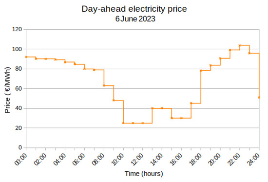
Figure 1.
24 h day-ahead electricity price for Belgium’s market.
3.2. Formulation of Dynamic Models
As shown in Figure 2, an equivalent circuit model was postulated to formulate the empirical model with degradation. The equivalent circuit model does not rely on any thermal model to incorporate temperature effects. Its holistic approach considers these effects embedded in the experimental data. The holistic approach aims to comprehensively analyse experimental data and understand how various factors interact to shape observed outcomes then uses a parameter identification procedure to estimate the best fitting curve. This model achieves enough accuracy to estimate the output voltage, load current, and power flow. It also maintains a manageable computational complexity to predict internal degradation.
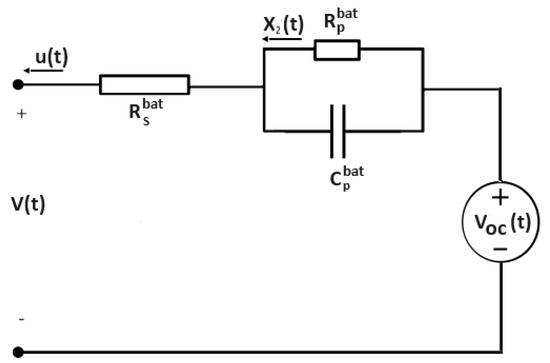
Figure 2.
Battery model: equivalent circuit model.
The state vector used to describe the equivalent circuit model is
where is the state of charge, is the current through the resistance (A), and , , and are extra states used to determine quantities of interest, as described below. The control variable u is the current from the battery (A). The convention used in the model implies that u is positive when the battery is discharging and negative when it is charging.
The model was partially extracted from [5] and augmented with three new state variables, namely, , , and , as shown in Equation (6):
where C is the nominal battery capacity in Ah, is the capacity degradation factor of Equation (5), and is the voltage across the battery terminals, given in Equation (7):
where is the function used to estimate the internal voltage, is the degradation factor given in Equation (5), and is the internal battery resistance. The time dependency of the degradation factors and is shown, as both of them depend of the electric charge Q passing through the battery, which varies with time.
The state of charge versus data points for a lithium-ion battery 18650 Li(NiMnCo)O2 were digitalised from the reference [37] and a seventh-order polynomial was used to fit the curve. Typical values for , and are = 15.80, = 8.2 , and = 38 kF [38]. The transient behaviour of the lithium-ion cell is characterised by the product of and [39].
States , , and are state variables required to estimate the RMS value of the terminal voltage , the mean value of the terminal voltage , and the total charge going through the battery , which is calculated as the integral of as follows:
3.3. Empirical Degradation Parameters
The research object of this work is the Sanyo UR18650E lithium-ion battery cell (Sanyo Electric Co., Ltd., Osaka, Japan), which has a cylindrical shape. According to the manufacturer, this cell is rated at ± 0.05 Ah, and its nominal voltage is 3.6 V. The cathode active material consists of Li(NiMnCo)O2, and the anode material is made of graphite. The grid-connected battery energy storage system modelled in this work is assumed to be composed of 750 UR18650E battery cells, with a total nominal energy storage capacity of 5.67 kWh. The battery cells were assumed to be arranged in a series/parallel configuration. It is important to note that although the cells are assumed to behave identically to simplify the analysis, slight differences in behaviour have been observed even among cells from the same production batch [40].
The empirical degradation model considers two crucial factors: battery cycling and calendar ageing. The model was extracted from [34], also using information from [18]. The model is based on the approach from Liaw et al. [41] in which a relatively simple equivalent circuit model simulates the battery performance and life cycling using a coupled thermal ageing model. However, all nonlinear parameters in the model were determined through empirical means. In the tests presented in [18], the authors found two different dependencies during cycling ageing analysis, one related to capacity reduction, or , and one to internal resistance increase, .
All the experimental data regarding battery capacity fading and resistance degradation used in this work were digitally obtained from reference [18]. However, all the curve-fitting procedures were revisited, and improvements in the fitting quality were implemented, as explained below.
To begin with, we examined the reduction in battery capacity due to battery cycling. The relationship between the capacity reduction during battery cycling and the charge that passes through the battery is determined by Equation (1). On the other hand, the increase in resistance during battery cycling and the charge passing through the battery is determined by Equation (3). The experimental data set to estimate the parameter were digitally extracted from reference [18]. The data points are shown in Table 1. The data showed that is strongly dependent on both the average battery voltage () and the depth of cycle .

Table 1.
Data points for the ageing factor for different average voltages (V) and depth of cycle (). The data in the table were created using the WebToolDigitizer, release v5. The data were sourced from reference [18].
In reference [18], the authors proposed a method for effectively linking the parameters and with the voltage and depth-of-discharge cycle. They suggested a linear function combined with a quadratic function, and while this approach is reasonably accurate, we chose to use a different methodology. We opted for the bilinear interpolation function, a feature provided by PSOPT, the optimal control solver used in this work [42]. We sampled the data based on voltage and depth of cycle, and the data points are presented in Table 1.
Second, we considered degradation in the capacity via calendar ageing. Here, the battery capacity varies with time, particularly with , according to Equation (3). The calendar ageing data showed that and strongly depend on the average battery voltage and the cell temperature T. Therefore, they can be approximated using a single two-variable interpolation function to fit both dependencies simultaneously.
It can intuitively be observed from the graphs that is linearly dependent on the voltage and follows the Arrhenius formula for temperature dependency according to the following equations:
where the variables , T, and R are the activation energy, temperature in Kelvin, and universal gas constant, respectively. The parameter is a combination of both results, as shown in Equation (13):
Equation (12) can be transformed into a linear function using the natural logarithm function, as shown in Equation (14):
The experimental data set to estimate the parameters and was digitally sourced from [18] using WebToolDigitiser. Employing linear regression yielded the subsequent linear approximation:
and exponential approximation:
and finally, the parameter is given in Equation (17):
Equations (15) and (17) cannot be combined into a single equation, as suggested in Equation (13), because the two fitting functions, and , do not match precisely for all the experimental data. Therefore, we use the technique proposed in reference [18]. The approach is to average and at K, where the two experimental curves intersect. The resulting value is named , and it is used for scaling both fitting functions to a single one. Then, apply this scale factor to the final equation.
From [18], at T = K is 0.0016368, and is 0.0001746702. Hence, the scale factor applied to is given in Equation (18):
Applying the scale factor to and ,
the resulting scale factor that needs to be applied to the fitting function is given in Equation (21):
and Equations (15) and (17) with (22), provide the final expression for is given in Equation (23):
The estimation of the total capacity lost considering cycling ageing and calendar ageing is the superposition of the as shown in Equation (1) and as shown in Equation (3).
A similar procedure was applied to find the values for degradation in the resistance, . The experimental data set to estimate the parameter was digitally extracted from Figure 12b of reference [18]. We used a bilinear interpolation function, which is provided in the optimal control solver, PSOPT. The data were sampled for different values of voltage and depth of cycle. The data points are shown in Table 2.

Table 2.
Data points for the ageing factor for different average voltages and depth of cycle (). The data in the table were created using the WebToolDigitizer, release v5. The data were sourced from reference [18].
The data showed that is strongly dependent on both the average battery voltage () and the depth of cycle .
3.4. Objective Functional Derivation
The objective functional, J for the empirical model, is shown in Equation (25):
where u is the control variable, which is the current from the battery, is the state vector, is the final time, and is the revenue (or cost of energy purchase) per unit of time, given by Equation (26):
where is the voltage defined in Equation (7), is a known price function that represents the actual price of energy in EUR/MWh at time t, N is the number of cells, and the factor converts the electricity price from EUR/MWh to EUR/Wh. Similarly, is the degradation cost defined by Equation (27):
where is defined in Equation (28):
where K is the ambient temperature. As our mathematical model does not include a coupled thermal model, we approximated the average temperature during the charging cycle in the empirical equations as the ambient temperature. Substituting Equation (28) into Equation (27), then J is given in Equation (29):
where the meaning of the variables and parameters in Equation (29) is given in Table 3.

Table 3.
Definitions of variables for the objective functional in the empirical battery model.
4. Optimal Control Problem Formulation
An optimal control problem is typically expressed as follows: the goal is to find the optimal state trajectory and the open-loop control function in order to optimise the objective functional J over the interval . The initial and final time are denoted by and , respectively, and . The variable is the independent variable. The objective functional is given in (30):
where is the end cost, the integral term is known as the running cost, and the scalar function is the integrand. The system is subject to the system state equations (i.e., dynamic constraints):
A set of inequality constraints can be used to express the initial and terminal conditions. These constraints are also known as event constraints:
The problem might also have time-dependent inequality constraints, often called path constraints:
where L and U refer to lower and upper bounds, respectively. The functions , , and are defined as per Equation (34):
and . There are, in addition, bound constraints on the decision variables as given in Equations (35)–(38):
The day-ahead problem is formulated as a single-phase optimal control problem, with the phase contained in the time interval , where and are fixed. The aim is to find the control trajectory , , and the state trajectory, x, , that minimises the objective functional, J, expressed in Equation (39), given the dynamics of the battery described in Equation (6).
where is defined in Equation (7), and within the relevant time window, where is the state of charge of the battery. In this research, the definition of is based on the methodology described in [5].
The bounds for the states and the control are given in Equation (40):
where is the maximum current from the cell in one hour.
A path constraint is included to prevent under/overvoltage damage, given in Equation (41):
The initial condition for the state vector is given in Equation (42):
and h is fixed.
Direct Numerical Methods for Optimal Control
Typically, with a few exceptions, optimal control problems are solved using numerical methods. In this work, we chose to use direct methods for optimal control as they offer several advantages over other approaches, as discussed in [43]. Direct methods for optimal control involve discretising the differential equations, constraints, and objective function associated with the problem and the numerical optimisation of the resulting nonlinear programming problem. Usually, nonlinear programming (NLP) methods are used for solving the resulting nonlinear programming problem. Different methods can be used to discretise the differential equations, constraints, and objective function, as discussed below.
Collocation methods consider the states and control variables as optimisation parameters, and the system of ODEs is regarded as nonlinear equality constraints in the discretised formulation. Then, a general NLP solver can produce a numerical solution to the discretised optimal control problem [44]. There are various approaches to collocation, but primarily, they can be divided into two groups. The first one is grounded on an implicit k-state Runge–Kutta scheme, as described in [43,45]. Euler, trapezoidal, and Hermite–Simpson are among the most widely used collocation methods, which use linear, quadratic, and cubic polynomial interpolation, respectively.
Suppose that the differential equations involved in the optimal control problem of interest consist of a set of state equations described as follows:
where defines the trajectory of the vector of state variables, defines the trajectory of the vector of control variables, t represents time, is a time interval, and is a vector function that defines the state equations. Assume that a set of discretisation points is defined as follows: , where , and M is an integer number. For a given integer , the discretisation step is defined as . Furthermore, define , and .
Euler’s method, which is based on a linear interpolation polynomial, is the simplest collocation method and is given in Equation (44):
The trapezoidal approach is based on a quadratic interpolant polynomial, and is shown in Equation (45):
Hermite–Simpson scheme is based on a cubic interpolant polynomial and is described by Equation (46):
Only a few authors have explored the use of collocation methods to solve optimal control problems associated with battery storage systems. A discussion paper [46] formulated a discretised optimal control problem to examine the influence that energy storage can have on energy generation and investment decisions. The problem was solved using Chebyshev collocation methods and dynamic programming. In [47], orthogonal polynomials were used to estimate the optimal control strategy for a hybrid storage configuration composed of batteries and ultracapacitors. Recent work [48] has addressed the optimal charging profile for a hybrid electric vehicle using an orthogonal collocation approach.
5. Results and Discussion
This study attempts to determine the battery operation over time that yields the optimal day-ahead energy dispatch by utilising market data from 6 June 2023. The measure to determine the solution quality used in this work is the maximum relative local error, which measures the accuracy of the approximation of the state variables and is described in detail in [49]. As mentioned, the day-ahead electricity price data were sourced from [36].
The problem was solved using mesh refinement with trapezoidal/Hermite–Simpson collocation methods. The mesh refinement algorithm was configured to perform up to seven iterations. Mesh refinement involves adjusting the mesh defined by the discretisation points by efficiently subdividing the existing cells into smaller ones in sections of the time domain where accuracy needs to be improved, resulting in a higher number of cells and a finer representation of the problem domain. This process allows for a more precise approximation of the control and state variables over the time domain of the problem. By refining the mesh, finer details and variations in the control and state variables can be captured, leading to more accurate optimisation results. However, it is essential to strike a balance between the accuracy of the solution and computational cost.
5.1. Numerical Simulation
This section presents the outcomes of our in-depth refinement procedure to improve our computational simulations’ accuracy and resolution. We studied three cases, which are summarised in Table 4. We aimed to improve the maximum local relative error of the solutions and provide the best solution for each particular case. The price of electricity was assumed to be constant within each hourly interval. Moreover, we assumed that the battery cells were not degraded at the beginning of the 24 h window.

Table 4.
Summary of the case studied to simulate the day-ahead problem.
5.2. Solver Configuration
All computations were carried out using the optimal control software PSOPT version 5.0. PSOPT [50] is an open-source, optimal control solver written in C++. The key parameters that define the solver configuration are given in Table 5.

Table 5.
Optimal control solver configuration.
5.3. Simulation Results
Table 6 shows a summary of key results for the three cases, including the profit, net revenues, degradation cost, and maximum relative local error achieved. Details on the results obtained for each case, including the mesh refinements process, accuracy and resolution of the simulations, the state of charge profile, the optimal current profile, and the terminal voltage profile are also presented.

Table 6.
Summary profits, net revenues, degradation cost, and best maximum relative error for each case. Profits and costs are in EUR per day assuming a battery storage system consisting of 750 Sanyo UR18650E lithium-ion cells.
5.3.1. Case 1: Maximising Net Revenues
In this scenario, the focus is on maximising net revenues without taking into account the cost of degradation. The state equations do not account for degradation, and it is assumed that the internal resistance value does not increase due to degradation effects. It is important to note that energy sales occur when the battery discharges (charging current is positive), meaning the system is selling energy to the grid, while energy purchases occur when the battery is being charged (charging current is negative), indicating the system is buying energy from the grid. Table 7 shows the mesh refinement results. The best maximum relative local error is , obtained for iteration seven, with a total number of discretisation points of 845. Table 6 shows the optimal profit obtained for this case, corresponding to EUR 7.82.

Table 7.
Results from the mesh refinement for case 1: maximise revenues with no degradation in the internal resistance.
Figure 3 shows the resulting state of charge over time in this case. Figure 4 displays the optimal current profile. The battery is charged at the beginning of the day and reaches 85% in about 1 h. Following that, for the next 10 h, the battery remains essentially unused. Between 11 h and 17 h, the battery goes through a charge/discharge cycle, then stays discharged until 22 h, when it starts charging again to about 85%.
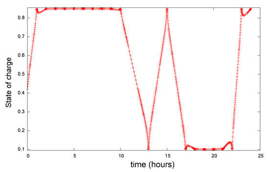
Figure 3.
State-of-charge profile for case 1, showing the charge/discharge schedule.
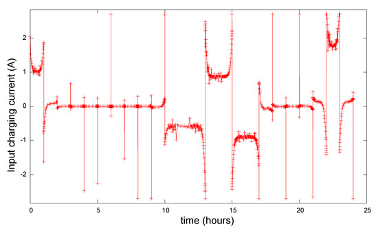
Figure 4.
Optimal current profile for case 1.
The voltage at the terminals is shown in Figure 5. Notice that the voltage increases/ decreases as the battery charges/discharges and that the voltage path constraint is respected.
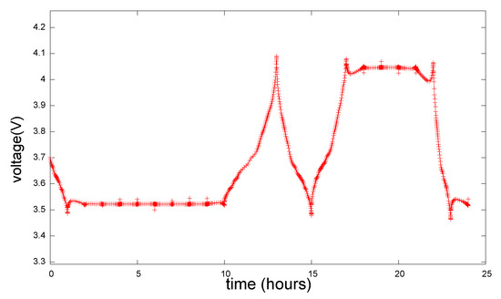
Figure 5.
Optimal voltage profile for case 1.
5.3.2. Case 2: Maximising Profits without Considering Degradation in the Internal Resistance
In this scenario, the aim is to maximise profits, which are calculated as the net revenue minus the cost of battery degradation. The state equations take into account the effect of degradation on the battery’s capacity but do not consider any increase in the battery’s internal resistance due to degradation. Similar to case 1, energy sales happens when discharging the battery (charging current is positive), while energy purchase occurs when charging the battery (charging current is negative). Table 8 shows the mesh refinement results for this case. The best maximum relative local error is 9.5225, obtained with a total number of discretisation points of 668.

Table 8.
Results from the mesh refinement for case 2: maximise profits.
Figure 6 shows the resulting state of charge over time. Figure 7 shows the optimal current profile for this case. Table 6 shows the optimal profit obtained for this case, which corresponds to EUR 4.769. The same table shows the net revenues and the cost of degradation for this case.
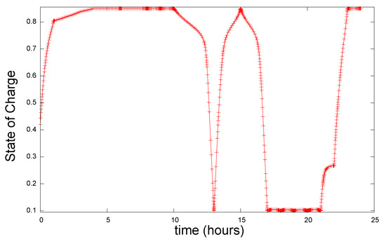
Figure 6.
State-of-charge profile for case 2, showing the charge/discharge schedule.
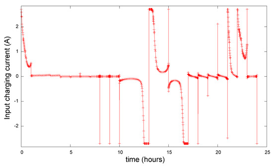
Figure 7.
Optimal current profile for case 2.
In this case, the battery is partially charged to about 80% after 1 h and then charges more slowly, reaching 85% at about 5 h, and then it stays inactive until about 10 h. Between 10 h and 13 h, the battery fully discharges, then charges again to about 85% at 15 h, then it starts discharging again until about 17 h. It remains discharged until about 21 h, when it starts to charge again to about 85% as the price of electricity starts reducing, making it cheaper to buy electricity from the grid. The terminal voltage profile for case 2 is shown in Figure 8.
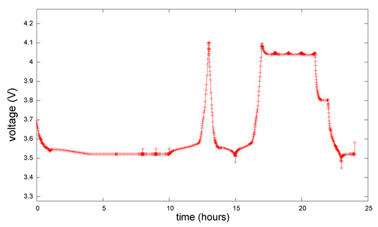
Figure 8.
Optimal voltage profile for case 2.
5.3.3. Case 3: Maximising Profits Considering Degradation in the Internal Resistance
In this case, the primary objective is to optimise profits by maximising the difference between net revenue and the cost associated with battery degradation. The approach involves using mathematical equations to model the system, considering the effects of degradation on both battery capacity and internal resistance. Battery degradation is anticipated to lead to a decrease in capacity and an increase in internal resistance over time, impacting the battery’s overall performance and efficiency. The results of the mesh refinement procedure are shown in Table 9. The best maximum relative local error is 2.372, obtained with a total number discretisation points of 671.

Table 9.
Results from the mesh refinement for case 3: maximise profits with degradation in the internal resistance.
Table 6 shows the optimal profit obtained for this case, which corresponds to EUR 4.768. The same table shows the net revenue and the cost of degradation associated with this case. Figure 9 shows the resulting state of charge over time. Figure 10 shows the optimal current profile. The results are very similar to those obtained in case 2; for instance, the profit values of cases 1 and 2 are only different in the third decimal digit, which indicates that introducing degradation to the internal resistance has a negligible effect on the profit value. The terminal voltage profile for case 3 is shown in Figure 11.
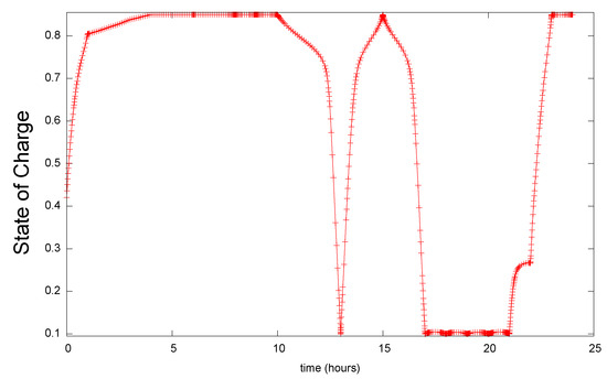
Figure 9.
State-of-charge profile for case 3, showing the charge/discharge schedule.
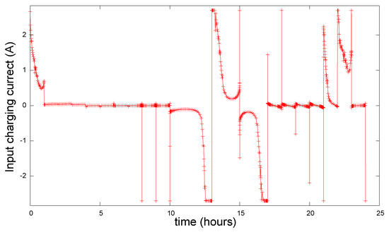
Figure 10.
Optimal current profile for case 3.
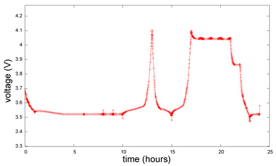
Figure 11.
Optimal voltage profile for case 3.
6. Conclusions
This work discussed the application of optimal control methods to optimise the participation of lithium-ion batteries in the day-ahead electricity market. Three cases were studied: maximising net revenues without consideration of degradation, maximising profits with consideration of capacity degradation, and maximising profits with consideration of degradation affecting both the battery’s capacity and the internal resistance. This study aimed to determine the optimal charge and discharge schedules for each case considering a 24 h price profile from Belgium’s day-ahead electricity market.
The results show that while the resulting charge/discharge profiles are similar in the three cases, consideration of capacity degradation in the dynamics and objective function reduces profits, while also including the increase in internal resistance due to degradation resulted in a reduction of EUR 0.001 in the profit value for the scenario considered in this work. On the other hand, considering only the maximisation of revenues, which translates into removing any degradation cost in the objective functional, profits were higher by EUR 0.31 compared with the case where degradation is considered.
Two areas for further research include the incorporation of a thermal model into the state equations so that temperature effects on degradation can be more accurately modelled and the validation of the optimal control methods presented here on a real battery energy storage system that participates in the day-ahead electricity market. Experimental validation will provide a further understanding of the real-world applicability of the proposed methods beyond the simulation-based studies presented in this work.
Author Contributions
Conceptualisation, J.G.-S. and V.B.; methodology, J.G.-S.; software, J.G.-S.; validation, J.G.-S. and V.B.; formal analysis, J.G.-S.; investigation, J.G.-S.; resources, J.G.-S. and V.B.; writing—original draft preparation, J.G.-S.; writing—review and editing, V.B.; visualisation, J.G.-S.; supervision, V.B. All authors have read and agreed to the published version of the manuscript.
Funding
This research received no external funding.
Data Availability Statement
The data presented in this study are available on request from the corresponding author. The data are not publicly available due to the first author’s PhD thesis not having been submitted at the time of publication of this work.
Conflicts of Interest
The authors declare no conflicts of interest.
References
- European Commission. Electricity Market Design. Available online: https://energy.ec.europa.eu/topics/markets-and-consumers/market-legislation/electricity-market-design_en (accessed on 26 September 2023).
- Gonzáles, N.; da Graça, M. Improving the Design of the EU Electricity Market. 2023. Available online: https://www.europarl.europa.eu/RegData/etudes/BRIE/2023/745694/EPRS_BRI(2023)745694_EN.pdf (accessed on 18 September 2023).
- Asija, D.; Viral, R. Chapter 13—Renewable energy integration in modern deregulated power system: Challenges, driving forces, and lessons for future road map. In Advances in Smart Grid Power System; Tomar, A., Kandari, R., Eds.; Academic Press: Cambridge, MA, USA, 2021; pp. 365–384. [Google Scholar]
- Teleke, S. Control Methods for Energy Storage for Dispatching Intermittent Renewable Energy Sources. Ph.D. Thesis, University of North Carolina, Raleigh, NC, USA, 2009. [Google Scholar]
- Reniers, J. Degradation-Aware Optimal Control of Grid-Connected Lithium-Ion Batteries. Ph.D. Thesis, Oxford University, Oxford, UK, 2020. [Google Scholar]
- Perez, H.E.; Hu, X.; Dey, S.; Moura, S.J. Optimal Charging of Li-Ion Batteries with Coupled Electro-Thermal-Aging Dynamics. IEEE Trans. Veh. Technol. 2017, 66, 7761–7770. [Google Scholar] [CrossRef]
- Zheng, L.; Zhou, X.; Qiu, Q.; Yang, L. Day-ahead optimal dispatch of an integrated energy system considering time-frequency characteristics of renewable energy source output. Energy 2020, 209, 118434. [Google Scholar] [CrossRef]
- Zhang, M.; Li, W.; Yu, S.S.; Wen, K.; Muyeen, S. Day-ahead optimization dispatch strategy for large-scale battery energy storage considering multiple regulation and prediction failures. Energy 2023, 270, 126945. [Google Scholar] [CrossRef]
- Fotopoulou, M.; Rakopoulos, D.; Blanas, O. Day Ahead Optimal Dispatch Schedule in a Smart Grid Containing Distributed Energy Resources and Electric Vehicles. Sensors 2021, 21, 7295. [Google Scholar] [CrossRef] [PubMed]
- Zhang, Z.; Wang, C.; Lv, H.; Liu, F.; Sheng, H.; Yang, M. Day-Ahead Optimal Dispatch for Integrated Energy System Considering Power-to-Gas and Dynamic Pipeline Networks. IEEE Trans. Ind. Appl. 2021, 57, 3317–3328. [Google Scholar] [CrossRef]
- Akkas, O.P.; Cam, E. Optimal operational scheduling of a virtual power plant participating in day-ahead market with consideration of emission and battery degradation cost. Int. Trans. Electr. Energy Syst. 2020, 30, e12418. [Google Scholar] [CrossRef]
- Fernández-Muñoz, D.; Pérez-Díaz, J.I. Optimisation models for the day-ahead energy and reserve self-scheduling of a hybrid wind–battery virtual power plant. J. Energy Storag. 2023, 57, 106296. [Google Scholar] [CrossRef]
- Tan, Z.; Tan, Q.; Wang, Y. Bidding Strategy of Virtual Power Plant with Energy Storage Power Station and Photovoltaic and Wind Power. J. Eng. 2018, 2018, 6139086. [Google Scholar] [CrossRef]
- Parastegari, M.; Hooshmand, R.A.; Khodabakhshian, A.; Zare, A.H. Joint operation of wind farm, photovoltaic, pump-storage and energy storage devices in energy and reserve markets. Int. J. Electr. Power Energy Syst. 2015, 64, 275–284. [Google Scholar] [CrossRef]
- Akkas, O.P.; Cam, E. Optimal Control of Battery Energy Storage for Wind Farm Dispatching. IEEE Trans. Energy Convers. 2010, 25, 787–794. [Google Scholar]
- Reiter, C.; Wildfeuer, L.; Wassiliadis, N.; Krahl, T.; Dirnecker, J.; Lienkamp, M. A holistic approach for simulation and evaluation of electrical and thermal loads in lithium-ion battery systems. In Proceedings of the 2019 Fourteenth International Conference on Ecological Vehicles and Renewable Energies (EVER), Monte-Carlo, Monaco, 8–10 May 2019; pp. 1–17. [Google Scholar]
- Reiter, C.; Lin, X.; Schlereth, L.; Lienkamp, M. Finding the ideal automotive battery concept. Forsch Ingenieurwes 2019, 83, 817–830. [Google Scholar] [CrossRef]
- Schmalstieg, J.; Käbitz, S.; Ecker, M.; Sauer, D.U. A holistic aging model for Li(NiMnCo)O2 based 18650 lithium-ion batteries. J. Power Sources 2014, 257, 325–334. [Google Scholar] [CrossRef]
- Wu, J.; Ihsan-Ul-Haq, M.; Chen, Y.; Kim, J.K. Understanding solid electrolyte interphases: Advanced characterization techniques and theoretical simulations. Nano Energy 2021, 89, 106489. [Google Scholar] [CrossRef]
- Ramadass, P.; Haran, B.; Gomadam, P.; White, R.; Popov, B. Development of First Principles Capacity Fade Model for Li-Ion Cells. J. Electrochem. Soc. 2004, 151, A196–A203. [Google Scholar] [CrossRef]
- O’Kane, S.E.J.; Ai, W.; Madabattula, G.; Alonso-Alvarez, D.; Timms, R.; Sulzer, V.; Edge, J.S.; Wu, B.; Offer, G.J.; Marinescu, M. Lithium-ion battery degradation: How to model it. Phys. Chem. Chem. Phys. 2022, 24, 7909–7922. [Google Scholar] [CrossRef] [PubMed]
- Amir, S.; Gulzar, M.; Tarar, M.O.; Naqvi, I.H.; Zaffar, N.A.; Pecht, M.G. Dynamic Equivalent Circuit Model to Estimate State-of-Health of Lithium-Ion Batteries. IEEE Access 2022, 10, 18279–18288. [Google Scholar] [CrossRef]
- Zhang, H.; Liu, W.; Dong, Y.; Zhang, H.; Chen, H. A method for pre-determining the optimal remanufacturing point of lithium ion batteries. In Proceedings of the 21st CIRP Conference on Life Cycle Engineering, Trondheim, Norway, 18–20 June 2014; Volume 15, pp. 218–222. [Google Scholar]
- Takei, K.; Kumai, K.; Kobayashi, Y.; Miyashiro, H.; Terada, N.; Iwahori, T.; Tanaka, T. Cycle life estimation of lithium secondary battery by extrapolation method and accelerated aging test: Proceedings of the 10th International Meeting on Lithium Batteries. J. Power Sources 2001, 97–98, 697–701. [Google Scholar] [CrossRef]
- Wang, J.; Liu, P.; Hicks-Garner, J.; Sherman, E.; Soukiazian, S.; Verbrugge, M.; Tataria, H.; Musser, J.; Finamore, P. Cycle-life model for graphite-LiFePO4 cells. J. Power Sources 2011, 196, 3942–3948. [Google Scholar] [CrossRef]
- Paffumi, E.; De Gennaro, M.; Martini, G. In-vehicle battery capacity fade: A follow-up study on six European regions. Energy Rep. 2024, 11, 817–829. [Google Scholar] [CrossRef]
- Li, X.; Wang, Q.; Yang, Y.; Kang, J. Correlation between capacity loss and measurable parameters of lithium-ion batteries. Int. J. Electr. Power Energy Syst. 2019, 110, 819–826. [Google Scholar] [CrossRef]
- Preger, Y.; Barkholtz1, H.M.; Fresquez, A.; Campbell, D.L.; Juba, B.W.; Romàn-Kustas, J.; Ferreira, S.R.; Chalamala, B. Degradation of Commercial Lithium-Ion Cells as a Function of Chemistry and Cycling Conditions: Proceedings of the 10th International Meeting on Lithium Batteries. J. Electrochem. Soc. 2020, 167, 120532. [Google Scholar] [CrossRef]
- Mandli, A.R.; Kaushik, A.; Patil, R.S.; Naha, A.; Hariharan, K.S.; Kolake, S.M.; Han, S.; Choi, W. Analysis of the effect of resistance increase on the capacity fade of lithium ion batteries. Int. J. Energy Res. 2019, 43, 2044–2056. [Google Scholar] [CrossRef]
- Krupp, A.; Beckmann, R.; Diekmann, T.; Ferg, E.; Schuldt, F.; Agert, C. Calendar aging model for lithium-ion batteries considering the influence of cell characterization. J. Energy Storag. 2022, 45, 103506. [Google Scholar] [CrossRef]
- Vetter, J.; Novák, P.; Wagner, M.; Veit, C.; Möller, K.C.; Besenhard, J.; Winter, M.; Wohlfahrt-Mehrens, M.; Vogler, C.; Hammouche, A. Ageing mechanisms in lithium-ion batteries. J. Power Sources 2005, 147, 269–281. [Google Scholar] [CrossRef]
- Weber, T.A. Optimal depth of discharge for electric batteries with robust capacity-shrinkage estimator. In Proceedings of the 2024 4th International Conference on Smart Grid and Renewable Energy (SGRE), Doha, Qatar, 8–10 January 2024; pp. 1–5. [Google Scholar]
- Shi, Y.; Xu, B.; Tan, Y.; Kirschen, D.; Zhang, B. Optimal Battery Control Under Cycle Aging Mechanisms in Pay for Performance Settings. IEEE Trans. Autom. Control. 2019, 64, 2324–2339. [Google Scholar] [CrossRef]
- Reniers, J.; Mulder, G.; Ober-Blöbaum, S.; Howey, D.A. Improving optimal control of grid-connected lithium-ion batteries through more accurate battery and degradation modelling. J. Power Sources 2018, 379, 91–102. [Google Scholar] [CrossRef]
- Zhou, B.; Liu, X.; Cao, Y.; Li, C.; Chung, C.Y.; Chan, K.W. Optimal scheduling of virtual power plant with battery degradation cost. IET Optim. Util. Storag. Syst. Transm. Distrib. Syst. 2016, 10, 712–725. [Google Scholar] [CrossRef]
- ENTSO. ENTSO—Transparency Platform. 2023. Available online: https://transparency.entsoe.eu/dashboard/show (accessed on 18 September 2023).
- Jiang, H.; Chen, X.; Liu, Y.; Zhao, Q.; Chen, B. Online State-of-Charge Estimation Based on the Gas–Liquid Dynamics Model for Li(NiMnCo)O2 Battery. Energies 2021, 14, 324. [Google Scholar] [CrossRef]
- Plett, G. Battery Management Systems, Volume I: Battery Modeling; Artech House Publishers: Norwood, MA, USA, 2015. [Google Scholar]
- Su, J.; Lin, M.; Wang, S.; Li, J.; Coffie-Ken, J.; Xie, F. An equivalent circuit model analysis for the lithium-ion battery pack in pure electric vehicles. Meas. Control. 2019, 52, 193–201. [Google Scholar] [CrossRef]
- Reniers, J.; Howey, D.A. Digital twin of a MWh-scale grid battery system for efficiency and degradation analysis. Appl. Eng. 2023, 336, 120774. [Google Scholar] [CrossRef]
- Liaw, B.Y.; Jungst, R.G.; Nagasubramanian, G.; Case, H.L.; Doughty, D.H. Modeling capacity fade in lithium-ion cells. J. Power Sources 2005, 140, 157–161. [Google Scholar] [CrossRef]
- Becerra, V.M. PSOPT Optimal Control Solver—User Manual (Version 02.09.2022). 2022. Available online: https://github.com/PSOPT/psopt/blob/master/doc/PSOPT_Manual_R5.pdf (accessed on 17 March 2024).
- Betts, J. Practical Methods for Optimal Control and Estimation Using Nonlinear Programming, 2nd ed.; SIAM: Philadelphia, PA, USA, 2010. [Google Scholar]
- Hargraves, C.R.; Paris, S.W. Direct trajectory optimization using nonlinear programming and collocation. J. Guid. Control Dynam. 1987, 10, 338–342. [Google Scholar] [CrossRef]
- Pytlak, R. Numerical Methods for Optimal Control Problems with State Constraints; Springer Verlag: Warsaw, Poland, 1991. [Google Scholar]
- Durmaz, T. Energy Storage and Renewable Energy; Technical Report; Norwegian School of Economics, Department of Economics: Bergen, Norway, 2014. [Google Scholar]
- Li, J.; Fu, Z.; Jin, X. Rule Based Energy Management Strategy for a Battery/Ultra-capacitor Hybrid Energy Storage System Optimized by Pseudospectral Method. Energy Proc. 2017, 105, 2705–2711. [Google Scholar] [CrossRef]
- Multani, S.S. Pseudospectral Collocation Method Based Energy Management Scheme for a Parallel P2 Hybrid Electric Vehicle. Master’s Thesis, The Ohio State University, Columbus, OH, USA, 2020. [Google Scholar]
- Betts, J. Practical Methods for Optimal Control and Estimation Using Nonlinear Programming, 3rd ed.; SIAM: Philadelphia, PA, USA, 2020. [Google Scholar]
- Becerra, V.M. PSOPT Optimal Control Software. 2020. Available online: https://www.psopt.net/ (accessed on 28 November 2022).
Disclaimer/Publisher’s Note: The statements, opinions and data contained in all publications are solely those of the individual author(s) and contributor(s) and not of MDPI and/or the editor(s). MDPI and/or the editor(s) disclaim responsibility for any injury to people or property resulting from any ideas, methods, instructions or products referred to in the content. |
© 2024 by the authors. Licensee MDPI, Basel, Switzerland. This article is an open access article distributed under the terms and conditions of the Creative Commons Attribution (CC BY) license (https://creativecommons.org/licenses/by/4.0/).