1. Introduction
The future of humanity is linked to finding new ways of generating and using energy that will save our planet. The final abandonment of fossil fuels must be compatible with the ubiquitous and constant supply of renewable energy. Relevant clean energy sources are intermittent, which has prompted the scientific community to find tools to overcome this problem. Over the last decades, lithium-ion batteries have emerged as satisfactory energy storage devices, providing high energy density, prolonged lifespan, and acceptable charging rates. Despite the success achieved, our society still fears a great dependence on a single resource, and, therefore, research into alternative electrochemical energy storage means is still in progress. In this way, new advances for alternative systems appear in the scientific literature, particularly for those that are based on the insertion of another alkali [
1,
2] and alkaline earth metal ions [
3,
4,
5]. Among them, sodium-ion batteries benefit from the substantial abundance of the alkaline element and the similarities between the chemical compounds of lithium and sodium [
6,
7,
8]. The latter factor enables the rapid overcoming of past difficulties associated with electrochemical sodium insertion and the implementation of these devices.
Layered oxides of sodium and transition metals exhibit insertion properties related to their lithium analogues and are therefore regarded as promising candidates to conform the cathode in commercial sodium-ion batteries. The most common layered structures of Na
xTO
2 (T: transition metal) compositions can be envisaged as an ordered stacking of oxygen in which the transition metal and sodium are found in alternate layers. The former is placed in octahedral holes, while sodium may occupy prismatic (P) or octahedral (O) holes. The structure of Na
2/3TO
2 denominated P2 consists of a trigonal prismatic site of the alkali element and two layers of transition metal in the repetition unit of the stack [
9]. In comparison with three-layer octahedral O3 structures NaTO
2, the diffusion of sodium ions is favoured in P2 solids, but the total capacity is limited to 2/3 Na per formula unit. The presence of manganese as the major element in T is attractive due to its environmental friendliness and low cost. To combine the structural stability supplied by manganese, which improves good capacity retention and decreases cell polarization during the charge/discharge cycles [
10] with high average discharge potential, a successful solution was P2-Na
2/3Ni
1/3Mn
2/3O
2 due to the reversible Ni
4+/Ni
2+ redox pair [
11,
12]. However, nickel is comparatively more expensive and less sustainable than iron. Unfortunately, the results published to date on P2-Na
2/3Fe
xNi
1/3-xMn
2/3O
2 compounds are far from optimal and require further investigation. Recently, many imaginative strategies such as cation substitution have been proposed to improve their electrochemical behavior [
13]. Among others, surface modification, replacement of Mn or Ni by electrochemically inactive elements (Zn, Mg, etc.), or controlled morphologies are intended to minimize unwanted interactions at the cathode–electrolyte interface (CEI) and avoid P2-O2 phase transitions [
14], facilitating sodium insertion at the same time.
On the other hand, it is well known that polymer additives to battery electrodes offer a significant improvement to mechanical stability and robustness, facilitating adequate shaping and adaptation to the current collector and effective packaging. Typical polymer additives include polyvinylidene fluoride (PVDF) or polytetrafluoroethylene (PTFE), with excellent thermal, chemical, and mechanical properties. In addition, the final electrode composition requires a conducting additive, commonly carbon black. Conductive polymers offer the particularly outstanding possibility to replace both additives. PEDOT:PSS or poly(3,4-ethylenedioxythiophene)-poly(styrene sulfonate) is a polymer resulting from the mixture of two ionomers. One of the components is made from sodium polystyrene sulfonate, which is a sulfonated polystyrene. The other component is poly(3,4-ethylenedioxythiophene), or PEDOT, a positively charged conjugated polymer based on polythiophene. Together, these charged macromolecules form a macromolecular salt that can be used directly as an additive to the electrode, which leads to multiple positive improvements: generating a conductive matrix to increase the electronic conductivity of the active electrode material, giving mechanical stability to the complete electrode, and acting as a protective coating to avoid the corrosion of the aluminum current collector. On the other hand, the facile handling of the monomer EDOT and its electrochemical polymerization offers a unique way to in situ generate the conducting PEDOT polymer simply by adding the monomer to the electrolyte and charging the cell to a convenient potential. Moreover, the performance of the PEDOT-bearing electrode improves substantially.
To improve the electrode/electrolyte interface, poly(3,4-ethylene dioxythiophene) (PEDOT) allows for different cost-effective methods to improve the performance of LiB [
15,
16] and SIB [
17,
18] electrodes. Composites of lithium-rich Li
1.2Ni
0.2Mn
0.6O
2 and poly(3,4 ethylene dioxythiophene): poly(styrene sulfonate) (PEDOT: PSS) were prepared through wet coating by Wu et al. [
15], and improved performance was observed after coating, particularly affecting the rate performance. The improvements were interpreted as a result of enhanced conductivity, accelerated electron transfer, preserved structural stability, reduced loss of material, and suppression of direct contact between the active electrode material and the electrolyte in the PEDOT-coated samples.
For LiFePO
4, different strategies have been developed, including the use of PEDOT: PSS wet procedures and in situ electropolymerization in one or two steps of the monomer alkyl thiophene (EDOT) in the battery itself. Electropolymerization yields coatings with conductive polymers that have the double role of improving electronic conductivity and protecting the surface of the active material [
16]. The latter methods differ when the addition of the monomer is carried out before or after the electrochemical lithium extraction from the phosphate electrode. The latter was found to be particularly useful for reaching capacities close to the theoretical values. In addition, low polarization, superior rate performance, and improved capacity retention were reported [
16].
Regarding phosphate cathodes for SIBs, the compound Na
3V
2(PO
4)
3 has also been successfully coated with PEDOT using an in situ self-decoration method by oxidative polymerization of the EDOT monomer. As a result, the material showed better electrochemical performance than both uncoated phosphate and a sample with a thick coating film of PEDOT, which was attributed to increased electronic conductivity and improved transmission of Na ions through the coating film [
17]. The storage mechanisms of NaFePO
4 coated with polythiophene (PT) as cathode material have also been investigated [
18]. The NaFePO
4/PT composite was prepared by starting with the chemical deinsertion of sodium from NaFePO
4, followed by coating with PT and chemical sodiation of the FePO
4/PT. Due to the strong interconnection between the cathode particles and the enhanced electrical conductivity induced by the PT layer, PT/NaFePO
4 cathodes exhibited better performance as compared with the uncoated electrodes. Thus, higher reversible capacities, capacity retention, and cycling efficiencies were described [
18].
Here, we will critically evaluate the possibility of using PEDOT-modified Na2/3Ni2/9Fe2/9Mn5/9O2 by four different procedures: in situ polymerization of the EDOT monomer during battery charging, the addition of PEDOT:PSS to the mixture or the current collector, and a combination of both additions.
2. Experimental Procedure
The synthesis of pristine P2-Na
2/3Ni
2/9Fe
2/9Mn
5/9O
2 (henceforth referred to as NFM) was carried out using a citric-based sol–gel method as previously reported [
19]. First, citric acid was dissolved in distilled water ensuring a citric acid/transition metal molar ratio (3:2). Stoichiometric amounts of iron, nickel, and manganese acetates were further poured to complete dissolution. Then, a 5% excess of sodium acetate was added to counterbalance evaporation losses during calcination. Subsequently, the solution was subjected to room-temperature stirring for 1 h. Solvent evaporation was achieved by heating the solution in a thermostated bath filled with ethylene glycol. To dry the resulting gel, it was maintained at 120 °C for one day. Then, pre-calcination at 450 °C in air was carried out for 2 h. As a result, the acetate groups were decomposed water was released. Finally, the precursor powder was ground, compressed into pellets, and annealed at 900 °C for 12 h in an air atmosphere. The resulting material was phase pure.
X-ray powder diffraction (XRD) patterns were obtained with a Bruker D8 Discover A25 apparatus using Cu Kα radiation, a Ge-monochromator, and a Lynxeye detector. The diffraction patterns were step-scanned between 2 and 90 (º2θ). The step size was 0.04º and the recording time was 672 s per step. To calculate the structure parameters, TOPAS v.4.2 software was used. Raman spectroscopy experiments were carried out with a Renishaw spectrometer using a 532 nm green laser light excitation source. Field Emission Scanning Electron Microscopy (FESEM), together with Energy Dispersive X-ray analysis (EDX) and composition mapping, were performed with a JEOL jsm 7800 microscope. X-ray photoelectron spectroscopy (XPS) was carried out with a SPECS Phobios 150 MCD spectrometer provided with Al Kα source. The samples were previously outgassed overnight under a high vacuum before the recording of the spectra. The binding energy calibration was carried out using the C1s line of the adventitious carbon at 284.6 eV as a reference. The Raman spectra were recorded by using a Renishaw Raman spectrometer provided with a green laser light (532 nm) as the excitation source.
The electrochemical experiments were carried out by using the synthesized NFM material as the working electrode in Swagelok™ type configuration sodium half-cells. A mixture of the cathode active material (75%), carbon black (15%), and polyvinylidene fluoride (PVDF) (10%) was dispersed in N-methyl-2-pyrrolidone for 2 h to obtain a homogenous slurry. The slurry was then spread on a 9 mm aluminium disk and dried under vacuum at 120 °C for three hours. The resulting working electrodes contained a mass loading of active material around 3 mg cm−2. The auxiliary electrode was a sodium metal disk, and the electrolyte was a 1 M NaPF6 1M solution in EC:DEC 1:1 v/v, which was impregnating the GF/A-Whatman glass fibre separators. The electrochemical cells were assembled in an MBraun argon-filled glove box under controlled O2 and H2O traces to perform voltammetric, galvanostatic, and impedance spectroscopy experiments. From the as-prepared compound, different procedures were essayed to prepare the PEDOT composites. (i) The in situ polymerization method employed EDOT monomer dissolved in the electrolyte in 0.02 M concentration, which yields PEDOT after in situ polymerization during the half-cell first charge, as discussed below (the electrode will be henceforth referred to as NFMp). On the other hand, the polymer PEDOT: PSS was also added in three different ways: (ii) manual mixing in a 79:7:7:7 proportion with the addition of ethylene glycol (NFMm); (iii) deposited on the collector with the original mixture (NFMc), and a combination of both methods (NFMb). Sodium half-cells assembled with the surface modified and pristine materials were subjected to galvanostatic cycling at different kinetics between C/10 and 2C within a potentials range of between 1.5 and 4.3 V. Cyclic voltammetry was performed in the 1.5–4.3 V potential window by using scan rates ranging between 0.1 and 1 mVs−1. Electrochemical Impedance Spectroscopy (EIS) data were collected for frequencies ranging from 1 mHz to 1 MHz.
3. Results and Discussion
The XRD patterns of as-prepared layered oxide showed the characteristic reflections for the hexagonal P2 structure (s.g. P6
3/mmc). The Rietveld refinement of the lattice parameters provided the values of
a = 2.90419(22) Å and
c = 11.16592(91) Å (
Figure 1 and
Table S1), which agree with previous reports on close compositions [
19]. The composition deduced from site occupancies—Na
0.68Ni
0.24Fe
0.24Mn
0.53O
2—differs little from the nominal formula. Irrespective of these differences, the oxidation state of Mn in our sample is ca. 4+, and thus the Jahn–Teller distortion predicted for Mn
3+ percentages higher than 10% [
20] is not expected. For Na
0.67Mn
0.65Fe
0.2Ni
0.15O
2, there is significant Mn
3+ content, but this phase was also described as hexagonal P2 [
19]. In contrast, other related compositions such as Na
0.55Ni
0.1Fe
0.1Mn
0.8O
2 [
21] and Na
0.67Ni
0.1Fe
0.1Mn
0.8O
2 [
22] were found to adopt the orthorhombic P’2 structure, due to their higher Mn
3+ content.
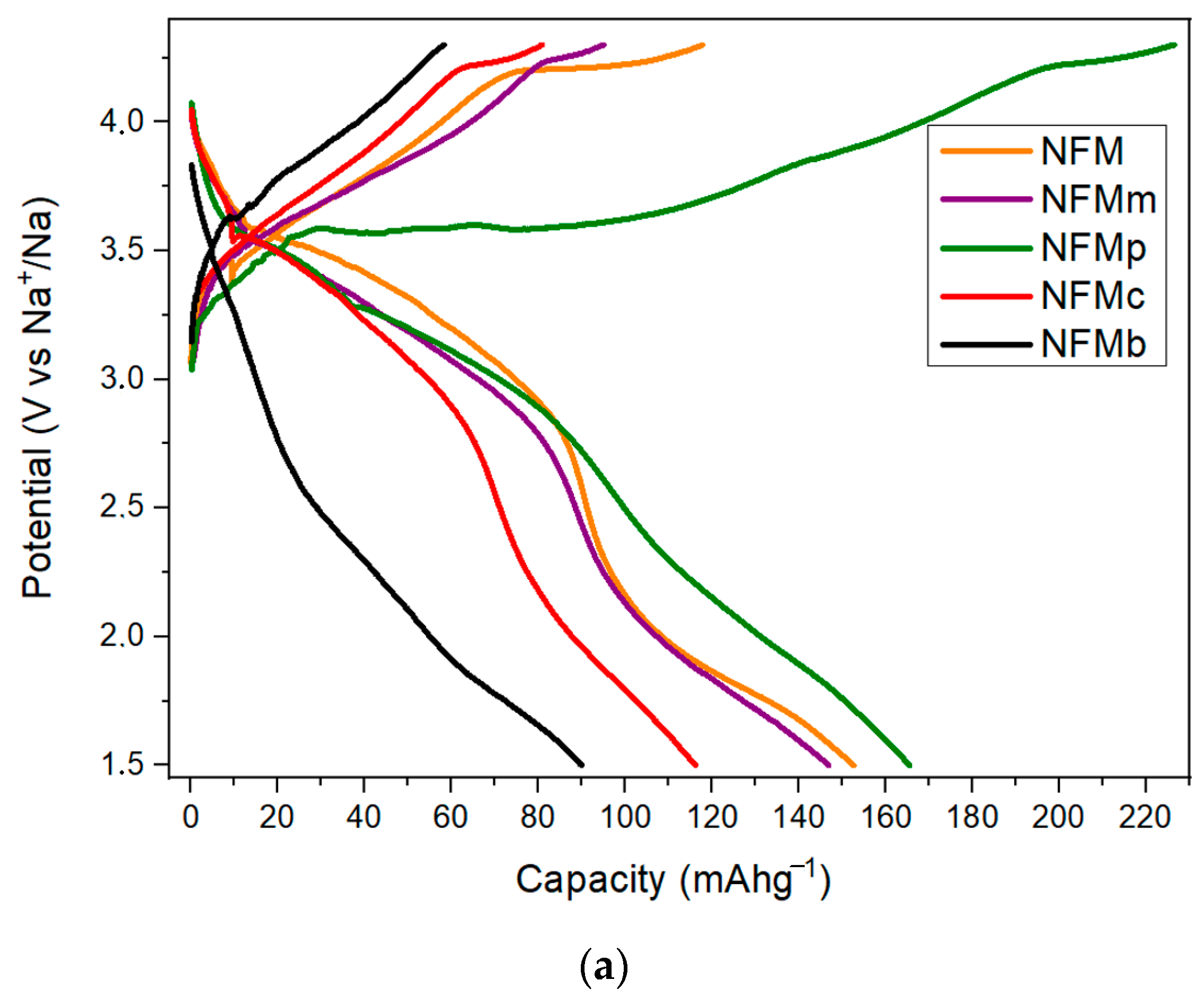
Figure 2a compares the first galvanostatic cycling profiles at C/10 for the Na
2/3Ni
2/9Fe
2/9Mn
5/9O
2 electrode and the composites with PEDOT. The pristine sample delivers a capacity of ca. 145 mAh g
−1 during the first charge up to 4.3 V, corresponding to approximately 84% of its theoretical capacity (173 mAh g
−1) based on the extraction of 2/3 moles of Na
+ ions together with the oxidation of all iron and nickel to 4+. This discrepancy could be the result of a slight deviation from the ideal Na stoichiometry or incomplete nickel and iron oxidation, as shown below. However, the first and second discharges in the 1.5–4.3 V potential window delivered ca. 152 mAh g
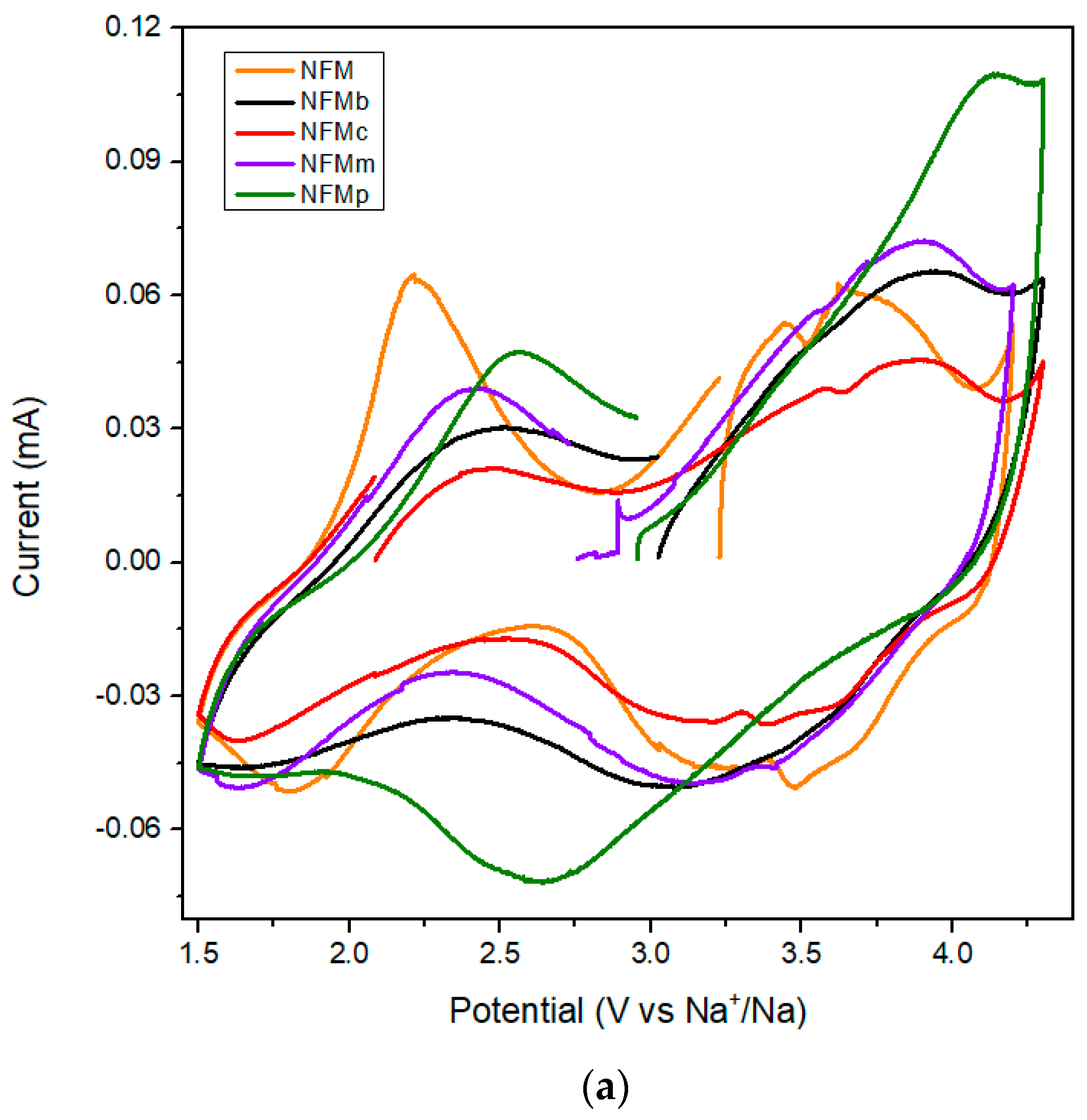
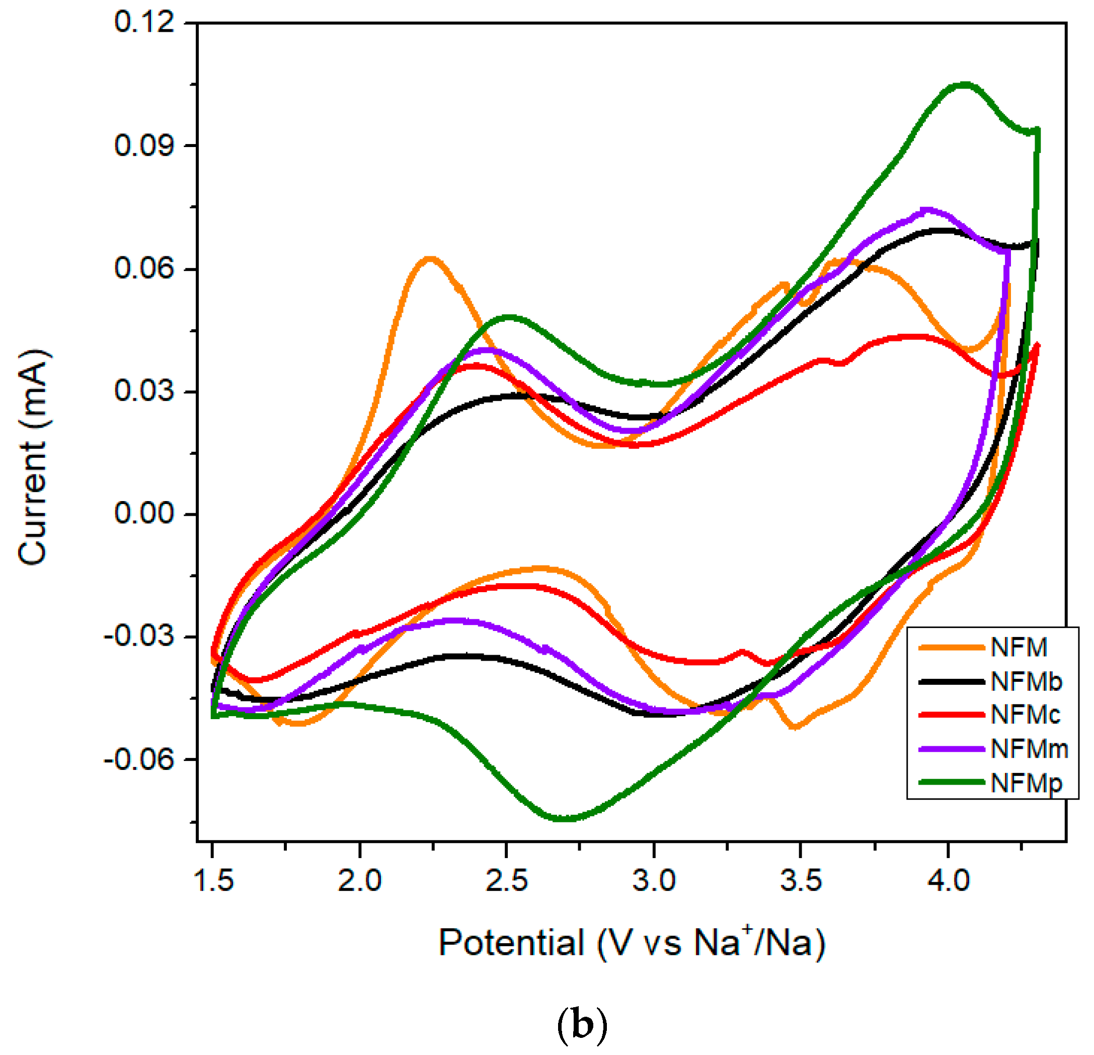
−1 in three lower slope voltage regions at 3.8/3.5 V, 3.4/3.2 V, and 2.4/1.8 V, in agreement with CV results recorded at 0.1 mV s
−1 (
Figure 3). These voltage regions imply the partial contribution of Ni
4+/Ni
3+/Ni
2+, Fe
4+/Fe
3+, and Mn
4+/Mn
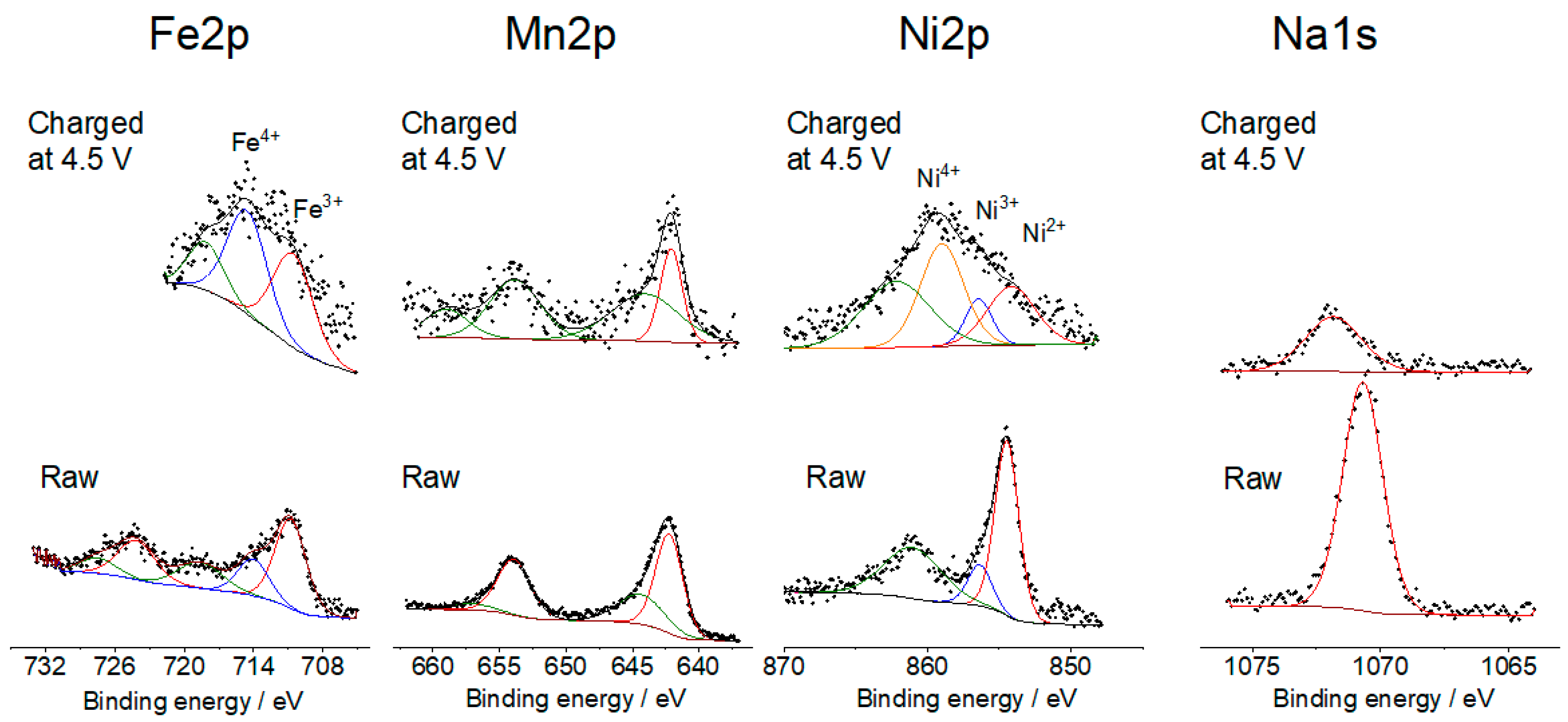
3+couples, respectively. XPS spectra of the raw and electrodes charged at 4.5 V (
Figure 4) support the contribution of these redox pairs on the surface of the NFM particles during sodium extraction, and the presence of residual Ni
2+ and Fe
3+, which may limit the total extraction–insertion of sodium. However, these results must be taken with care, as the XPS technique examines the surface of the active electrode particles, which may differ from the bulk.
The fact that the capacity of NFM decreases at the beginning and then increases again during charging is commonly found in the first cycle of water-absorbed samples. However, the overall capacity does not reach the full extraction–insertion of 2/3 Na. By comparison to the pristine sample, the PEDOT:PSS-added electrodes in the three different forms display similar or lower capacities. The poor discharge capacity of NFMc and NFMb reflects the difficulties in incorporating the polymer into the composite with the active material, and the fragile composites obtained by the electrode collector coating with the polymer. In fact, during electrode processing, the cohesion between the current collector and electrode slurry was poor, thus damaging the electrical contacts and the efficient utilization of the sodium storage capacity of the active material.
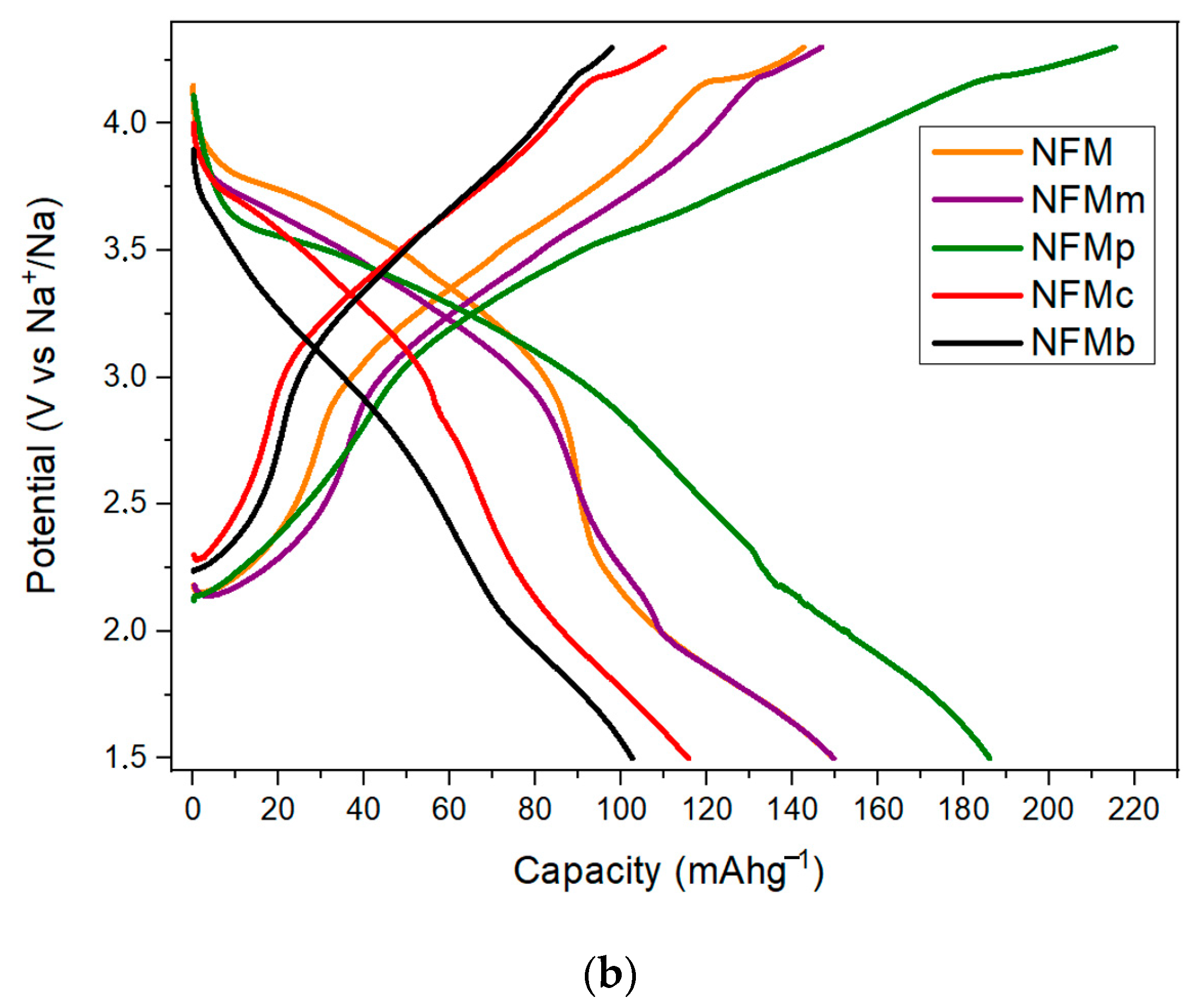
However, the in situ electropolymerization performed by the EDOT addition to the electrolyte leads to a much more extended first charge branch, up to ca. 225 mAh g
−1, which is above the theoretical value for NFM. The extra capacity is developed between 3.8 and 4.2 V (
Figure 2a) and is also evidenced as an incipient 4.0 V peak in the CV results (
Figure 3). This extra capacity lowers in the second charge (
Figure 2b) and is absent in further cycles. This signal in the first two cycles can be ascribed to the progressive electropolymerization of EDOT. The amount of added monomer fits well with the charge consumed in the formation of PEDOT, according to the previous literature [
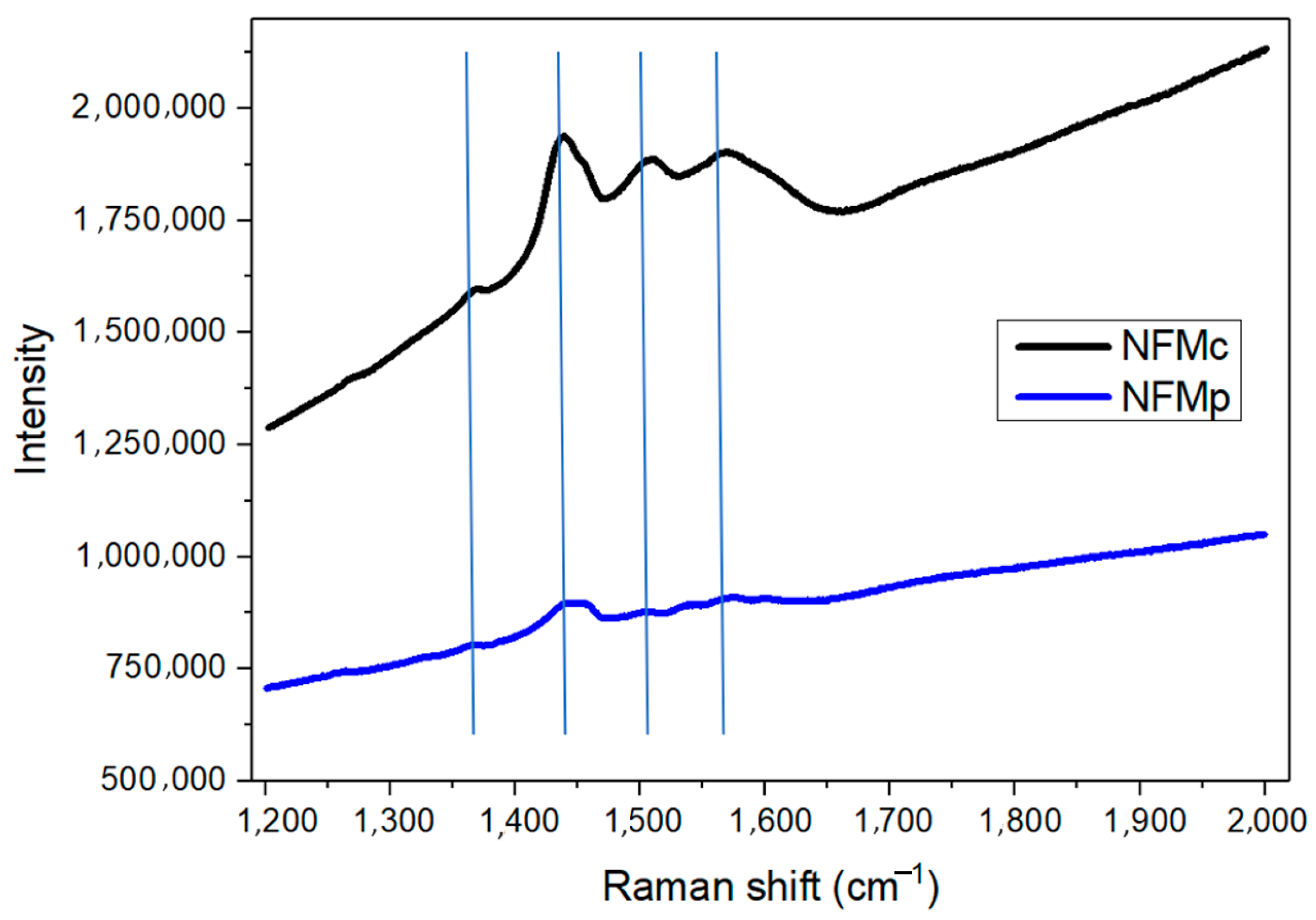
23]. Also, the formation of the polymer was checked by Raman spectroscopy of the charged electrode in the 1200–2000 cm
−1 region where the most intense lines ascribable to PEDOT appear (
Figure 5). Thus, the weak signal at 1368 cm
−1 is ascribable to the C
β-C
β stretching mode, the most intense band at ca. 1438 cm
−1 is ascribable to symmetric C
α=C
β(–O) stretching, and the one at 1508 cm
−1 to asymmetric C=C stretching. The peak observed around 1559 cm
−1 that is observed in NFMc but appears very weak in NFMp is ascribable to the splitting of the asymmetric C=C stretching, also described in the literature [
23]. The spectra are also consistent with that of commercial PEDOT. On the other hand, NFMp also shows larger discharge capacities as compared to the pristine NMF sample. This improvement can be considered a consequence of the increased accessibility to the overall electrode active material in the composite containing the conducting polymer.
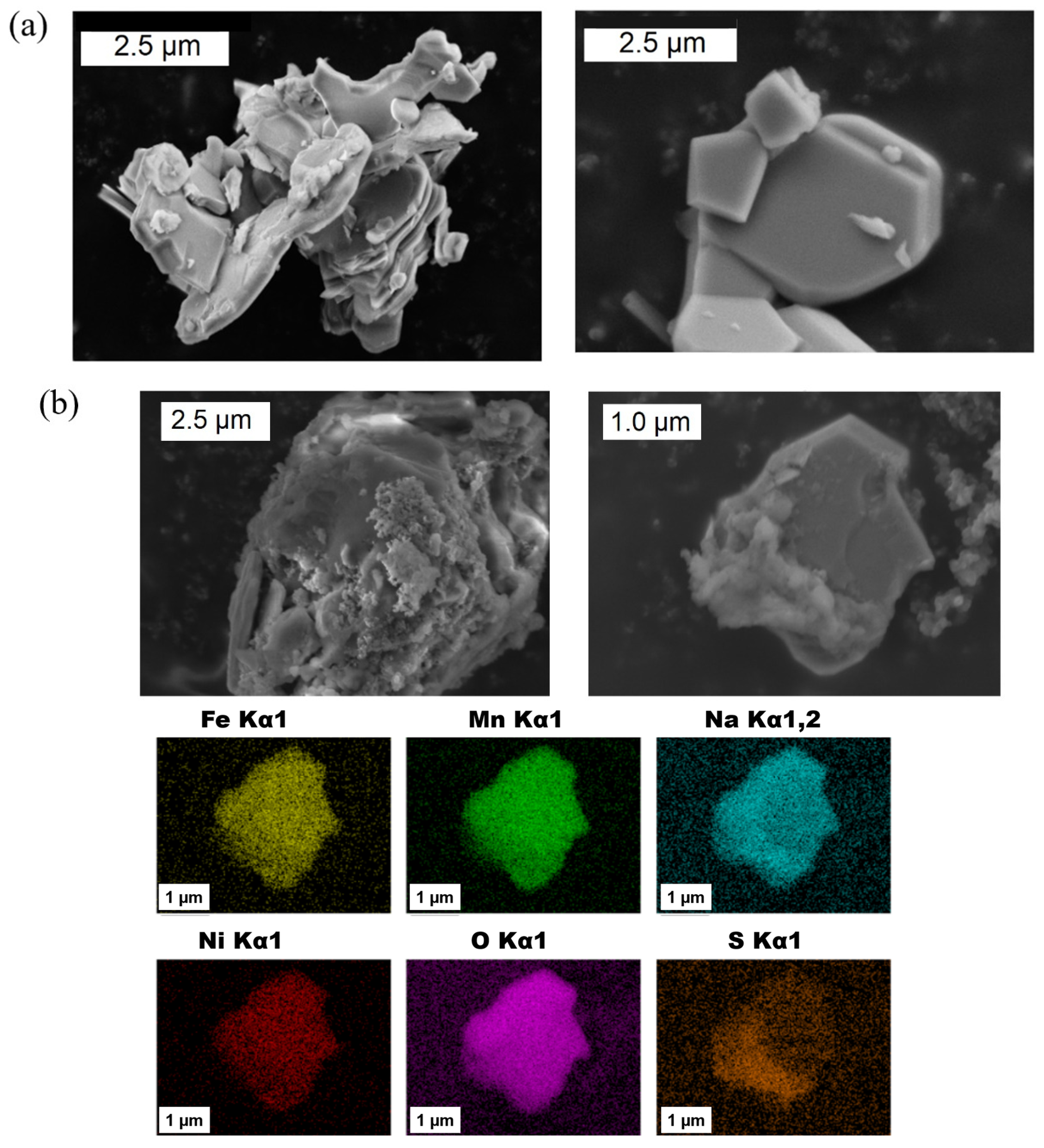
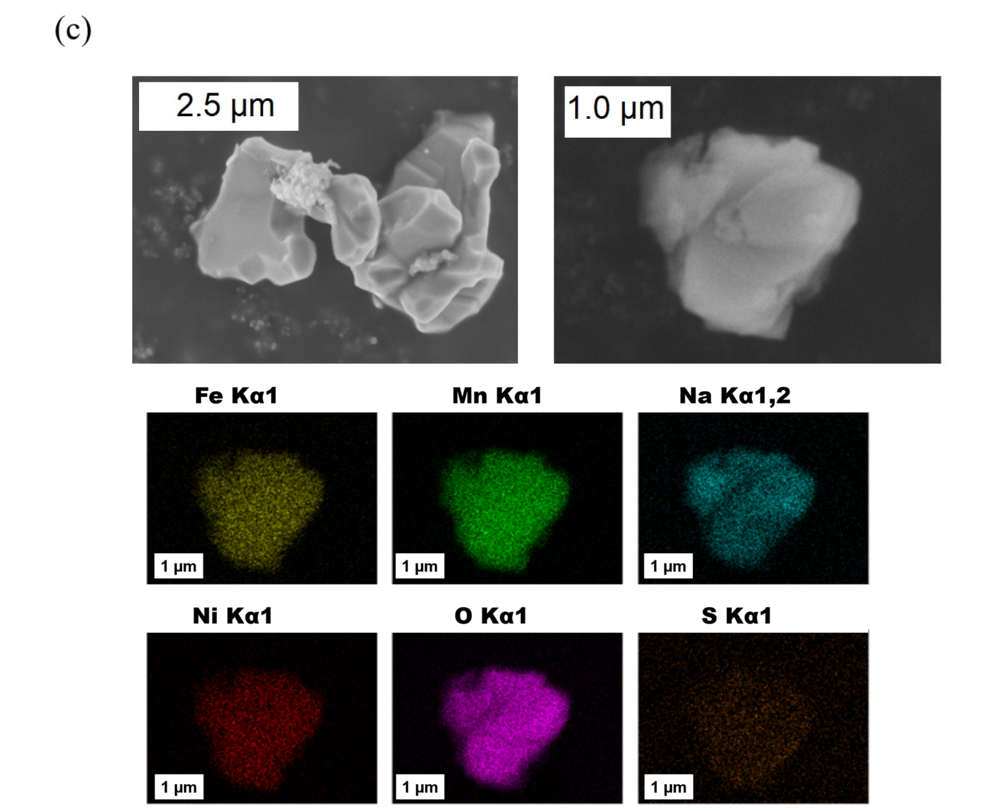
FESEM images of the NFM sample (
Figure 6a) show particles ranging from 0.5 to 2 μm with a characteristic layered habit. For the NFMp sample (
Figure 6b), the composition map shows a homogeneous distribution of Na, Fe, Ni, Mn, and O in the particle, as expected from the sol–gel synthesis procedure. However, polymer and layered oxide can be differentiated in the images and sulfur content map. Nevertheless, good contact between both regions is indicative of good electrical connectivity. Regarding NFMm (
Figure 6c), the particles are not covered by the polymer but gain contact by pressing the electrodes.
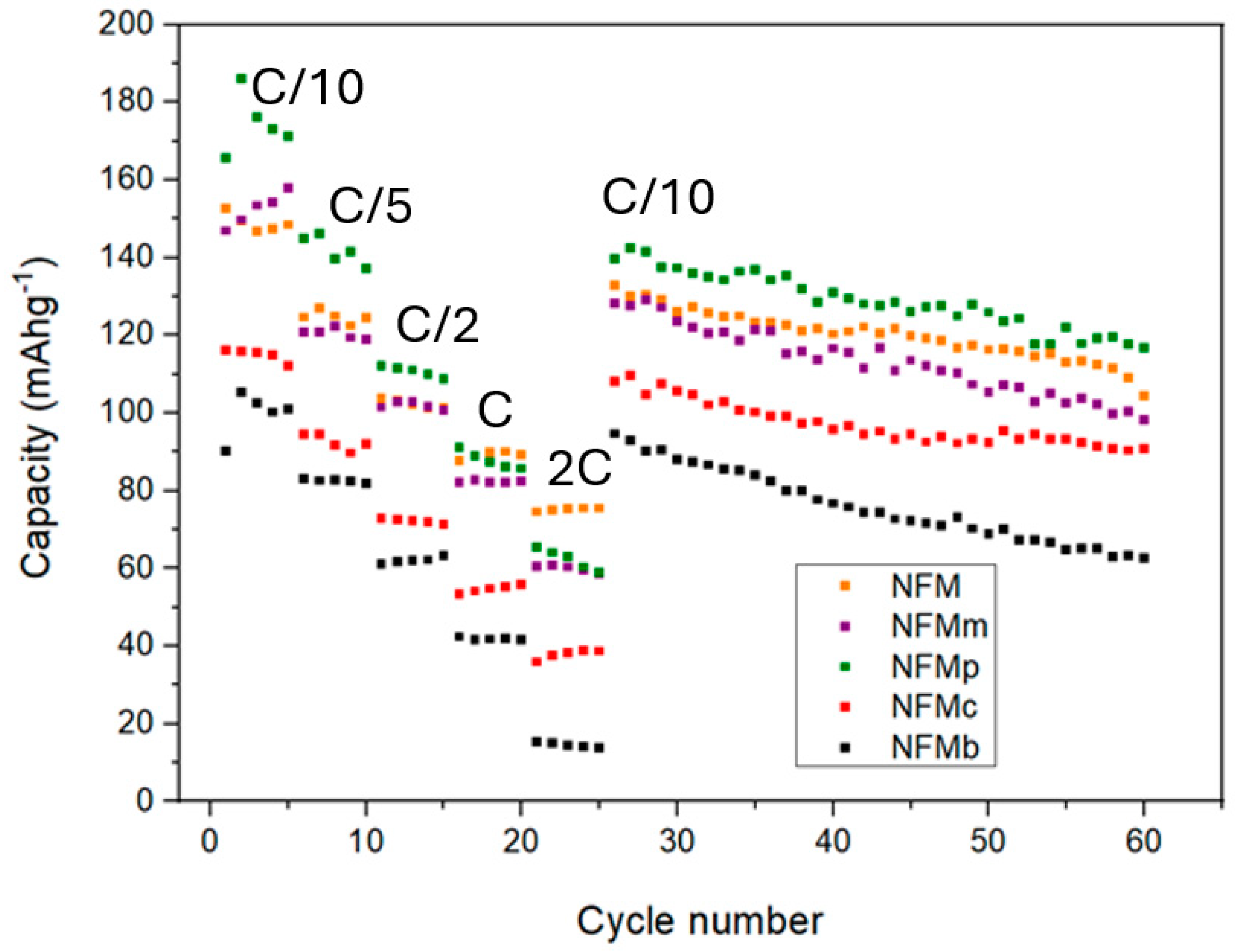
The rate performance and cycling stability of the different electrodes are depicted in
Figure 7. During the variable rate cycles, the capacity of all the half-cells studied decreases progressively as the rate increases. In the initial cycles at a low rate (C/10), both NFMp and NFMm composite outperform the NFM sample. At moderate rates (C/5-C/2), only NFMp outperforms the pristine NFM sample. As the rate decreased again to the initial C/10 value, NFM and NFMp except for NFMb and NFMm recovered a larger percentage of their initial capacity. After 40 additional cycles at C/10, NFMp retains a larger capacity than NFM. Comparing the performance of the composites prepared by the electrode coating method, it is evident that the in situ EDOT polymerization on the NFM active material provides a good substrate that favors the formation of a more extended conductive and uniform polymer deposit. The enhanced cyclability obtained for the NFMp cathode material suggests that the PEDOT obtained over NFM by this procedure is more chemically and mechanically stable, as a consequence of being generated in situ under the battery environment. In order to check this assumption, FESEM images of the NFMp electrode after 25 cycles were recorded. By comparing
Figure 6b with
Figure S1, the similarity in sulfur distribution on the surface and the edges of the particles, as well as the preservation of NFM particle size, are in good agreement with the enhanced electrode stability.
The charge transport properties of the pristine and composite electrode materials are discussed below considering EIS, cell polarization, and sodium diffusivity.
Figure 8 shows the Nyquist plots corresponding to three-electrode cells using the five studied samples as active material in the working electrode, and sodium metal in both reference and counter-electrodes. For each sample, the three measurements were collected: at OCV, after the first cell charge, and after the first cell discharge. The equivalent circuit used to fit the data is also shown, which was selected according to previous reports in the literature [
15,
24]. At high-to-medium frequency, R
e corresponds to electrolyte resistance, and R
sl and Q
sl to the resistance and constant phase element, respectively, of the interface surface layer between active material and electrolyte. R
ct and Q
ct result from the resistance and constant phase element of charge transfer. Z
w is the Warburg element in the low-frequency region. The resulting fitting parameters are collected in
Table S2. The spectra show that all electrodes have an initially high overall impedance. However, during the first cycle, a notorious decrease in Z’ was observed when the EDOT monomer was added to the electrolyte, thus evidencing the polymerization–doping process with the subsequent increase in electronic conductivity in the NFMp electrode. Considering the different contributions to the overall resistance that are shown in
Table S2, R
e is expected to be negligible in comparison with the values in
Table S2, being low for all cells, as it results from the electrolyte solution, and was disregarded. The improvement in the presence of conducting polymer as a mixture or after the polymerization relates to a reduction in both R
sl and R
ct, which implies that the enhancement in conductivity favours the interphase and charge transfer phenomena.
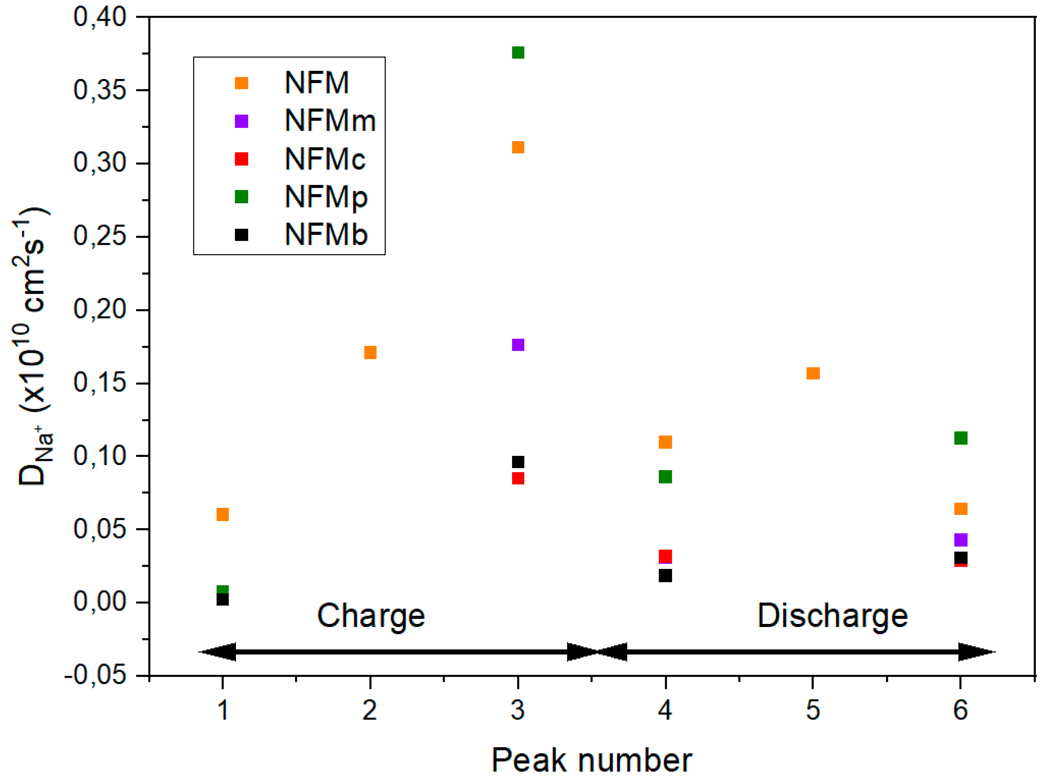
Apparent diffusion coefficients were obtained from cyclic voltammograms recorded at several kinetic rates ranging from 0.1 to 1 mV s
−1 (
Figure S2). Three redox anodic peaks, numbered 1–3 in
Figure S1, and their corresponding cathodic peaks (4–6) were observed, which are highly coincident with the voltage pseudoplateaus described above. The Randles–Sevcik model [
25,
26] allows for the calculation of apparent diffusion coefficients (
DNa+) from the proportionality between current intensity at the peaks’ maxima (
Ip) with the square root of the sweep rate (
υ1/2), according to the following equation:
where the number of electrons transferred in the redox reaction is represented by
n, the geometric area of the electrode by
S, and the bulk concentration of electroactive
Na+ by
C0. A clear linearity was shown when
Ip was plotted against
υ1/2 for the six peaks. The apparent sodium diffusion coefficients calculated from the slopes are shown in
Figure 9. Globally, the PEDOT-free material shows the highest
DNa+ values, which agree well with the good rate performance of the pristine sample. However, better diffusivity is observed by in situ polymerization in the third and sixth peaks, which can explain the impedance reduction kinetic response and the reduction in impedance. The increased diffusivity can be associated with the filling of space in the composite electrode by the conductive polymer, as reported in the previous literature [
27].
Among the different strategies to improve the performance of cathodes for LIBs and SIBs [
15,
16,
17,
18,
28,
29], in situ DOT electropolymerization appears an easy and efficient method to improve electrode stability.


