Article

Equivalent Noise Analysis and Modeling for a Magnetic Tunnel Junction Magnetometer with In Situ Magnetic Feedback

1
Center for Integrated Spintronic Devices, Hangzhou Dianzi University, Hangzhou 310018, China
2
School of Electric Power Engineering, Nanjing Normal University Taizhou College, Taizhou 225300, China
3
School of Information Science and Technology, Hangzhou Normal University, Hangzhou 311121, China
4
Jason Automotive Technology Co., Ltd., Wuhan 430058, China
*
Authors to whom correspondence should be addressed.
Magnetochemistry 2023, 9(10), 214; https://doi.org/10.3390/magnetochemistry9100214
Submission received: 1 August 2023 / Revised: 11 September 2023 / Accepted: 26 September 2023 / Published: 29 September 2023
(This article belongs to the Special Issue New Trends in Spintronic Materials and Devices)

Abstract

:
Magnetic tunnel junction (MTJ) sensors have been one of the excellent candidates for magnetic field detection due to their high sensitivity and compact size. In this paper, we design a magnetometer with in situ magnetic feedback consisting of an MTJ sensor. To analyze and evaluate the detectivity of the MTJ magnetometer, a noise model of the MTJ sensor in the magnetometer without magnetic feedback is first developed. Then, the noise model of the MTJ magnetometer with in situ magnetic feedback is also established, including the noises of the MTJ sensor and the signal conditioning circuit, as well as the feedback circuit. The equivalent noise model of the MTJ magnetometer with in situ magnetic feedback is evaluated through nonlinear fitting for the noise voltage spectrum. Although the noise generated by the MTJ sensor is much greater than that of the signal conditioning circuit, the noise introduced by the feedback coils into the MTJ sensor is slightly more than twice that generated by the MTJ sensor itself. The measurement results show that the detectivity of the MTJ magnetometer with in situ magnetic feedback reaches 526 pT/Hz1/2 at 10 Hz. The equivalent noise analysis method presented in this paper is suitable for the detectivity analysis of magnetometers with magnetic feedback.

1. Introduction

The magnetic tunnel junction (MTJ) sensor has been shown to have the ability to sense magnetic fields at levels as low as tens of pT and have been broadly applied in many important areas such as geomagnetic detection, magnetic anomaly detection, and navigation [1,2,3,4,5,6,7,8,9]. Usually, an MTJ sensor is combined with a voltage amplifier (VA), feedback circuit, and analog-to-digital converters (ADCs) to form a closed-loop magnetometer as a way to increase the measurement range of the MTJ sensor and improve the linearity of the system [10,11,12,13,14]. Andrea et al. constructed a closed-loop system employing an instrumentation amplifier (INA), integrator, and power amplifier (PA) to address the effects of the hysteresis, nonlinearity, and operating temperature of magnetoresistive sensors on measurement uncertainty.
For the detection of ultra-low magnetic fields, the noise of the closed-loop magnetometer is vital for the detectivity of the system. Currently, noise research has mainly focused on the noise analysis of the MTJ sensor itself [1,2,15,16,17,18,19,20,21,22,23]. Paulo et al. summarized the noise generation mechanism in the MTJ sensor and the application of the MTJ sensor in weak magnetic field detection [2]. Naganuma et al. fabricated MTJs with a composite free layer and measured the field and temperature dependences of the low-frequency noise to understand the origin of noise [19]. Zhang et al. proposed an equivalent noise model to deal with the deviation between the output noise of the MTJ sensor and its intrinsic noise by considering both the noise sources and the corresponding noise transfer functions [18]. However, less work is reported on the noise analysis of the signal conditioning circuit [24]. It is critical to determine all of the noise sources of the MTJ magnetometer to obtain a higher detectivity. Gao et al. studied the equivalent noise of an MTJ magnetometer, while it adopted an open-loop structure and could only be applied to a small range of magnetic fields. In addition, this work did not give the noise spectra under different bias magnetic fields, which was also important for the noise analysis [24]. Du et al. designed planar spiral coils to compensate for the bias magnetic fields at the MTJ sensing element in order to maintain the actual magnetic field detected by the MTJ sensing element constant. The system was essentially an open-loop structure, and the compensating magnetic field could not adaptively change according to the bias magnetic field. The effect of each noise source in the signal conditioning circuit on the detectivity of the system was not analyzed in their paper [25].
In this paper, an MTJ magnetometer with in situ magnetic feedback is designed and fabricated, and an equivalent noise model is established by considering all the noise sources including the MTJ sensor, the signal conditioning circuit, and the feedback circuit. Through modeling and analysis, the maximum noise source is determined, and the detectivity of this magnetometer is predicted. The research results indicate that the noise introduced by the feedback coils into the MTJ sensor in the low-frequency regime is higher than the noise of the MTJ sensor itself. Therefore, the design of the feedback circuit is key to further improving the detectivity of the magnetometer, which provides an important theoretical and experimental basis for the design and optimization of the closed-loop magnetometer in future work.

2. Design of MTJ Magnetometer with In Situ Magnetic Feedback

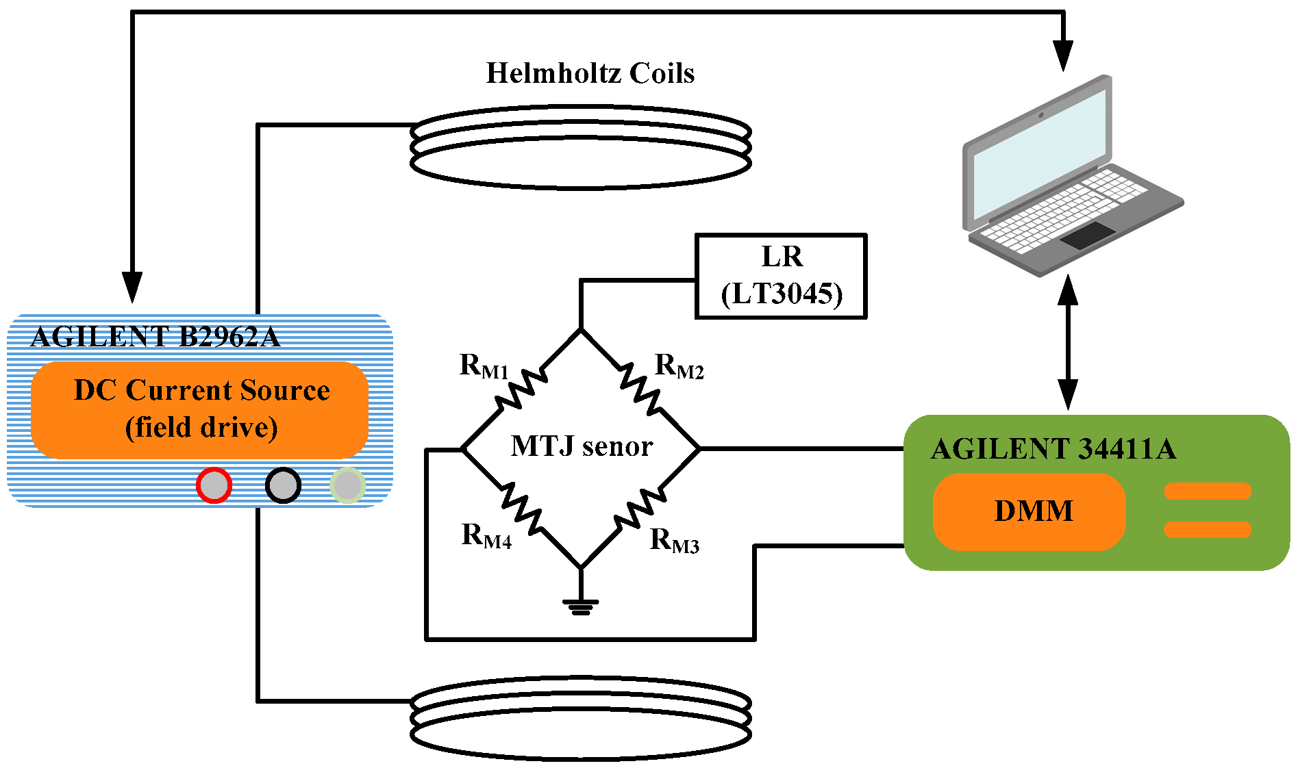
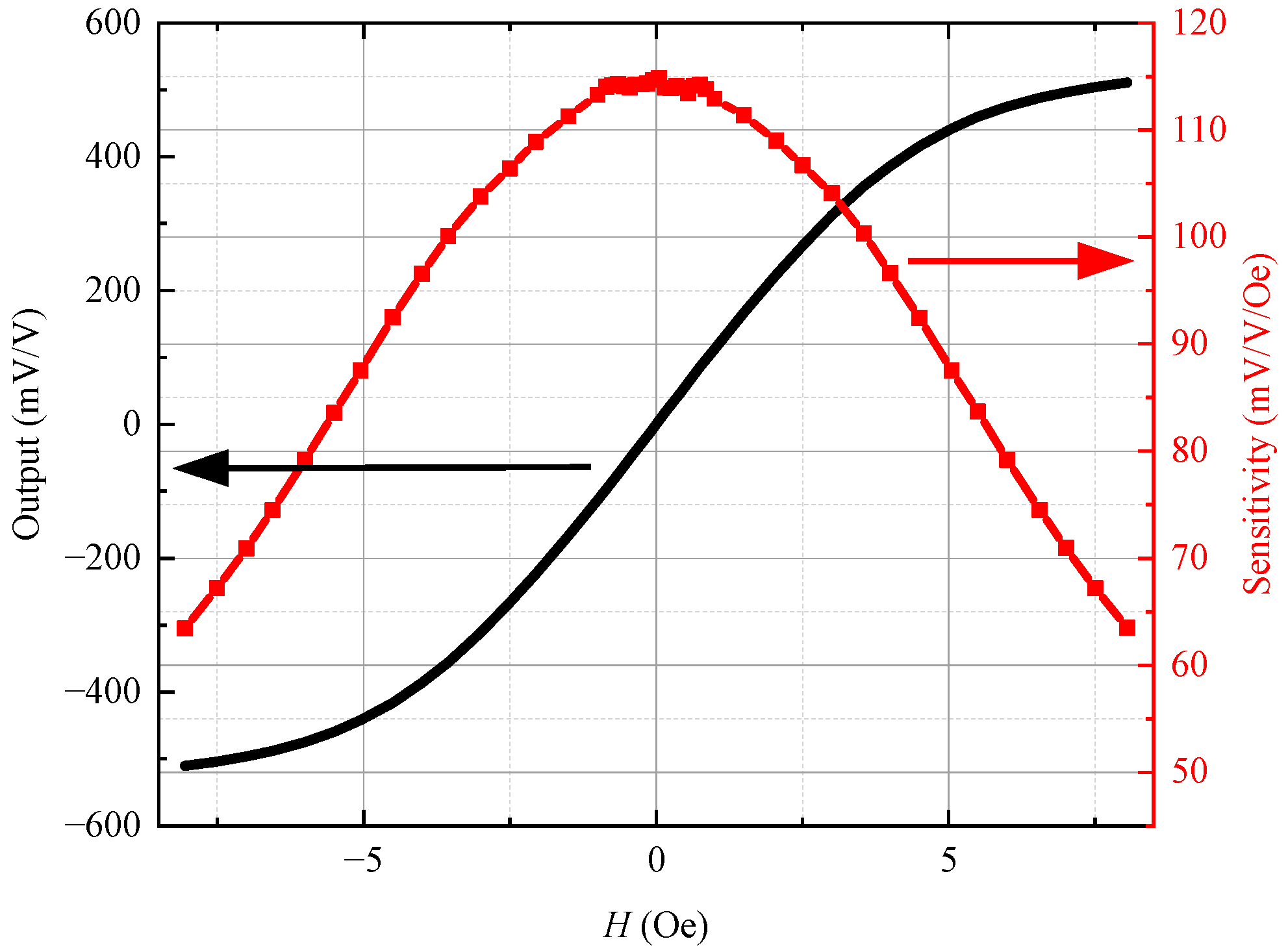
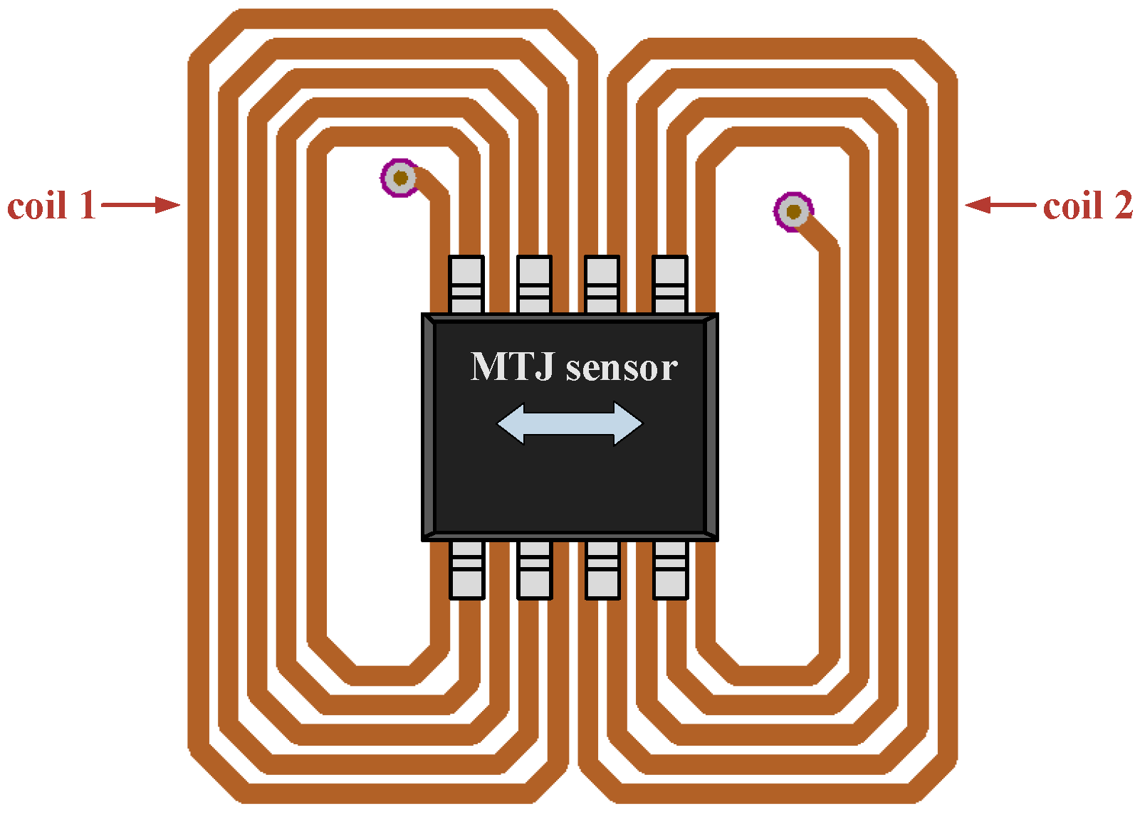
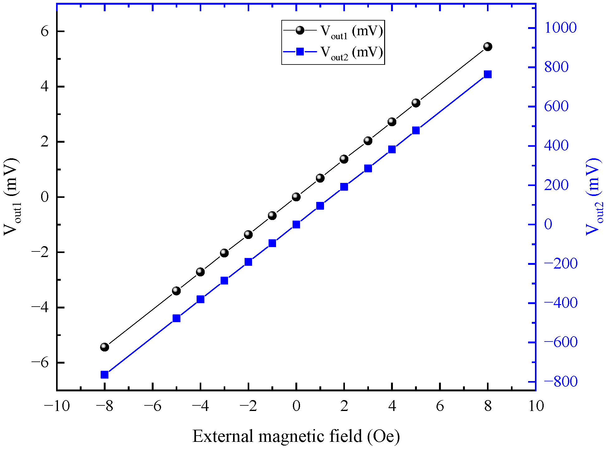
2.1. Magnetic Field Sensing Element

The magnetometer adopts an MTJ sensor as the magnetic field sensing element. The MTJ sensor has a Wheatstone bridge configuration with a resistance of 44.7 kΩ at room temperature (290 K). Each bridge arm consists of 160 MTJs connected in series. The structure of the MTJs is Ta/Ru/PtMn/CoFe/Ru/CoFeB/MgO/CoFeB/NiFe/Ta, and the area of a single MTJ is about 120 μm2. The MTJ sensor is available in the SOP8 package.
To characterize the sensitivity, the MTJ sensor is placed at the center of the Helmholtz coils, and a linear regulator (LR) is used to provide a bias voltage of 1 V to the MTJ sensor, as shown in Figure 1. The transfer curve of the MTJ sensor can be obtained by sweeping the magnetic field with a computer-controlled DC source to vary the current in the Helmholtz coils. The current-to-magnetic field conversion ratio of the Helmholtz coils is 2.05 Oe/100 mA at the MTJ sensor, as measured by a gaussmeter. A digital multimeter (DMM) is used to capture the differential output of the MTJ sensor, and it also communicates with a laptop computer in which the data can be analyzed.
Figure 2 shows the output and sensitivity of the MTJ sensor as black and red curves, respectively. The MTJ sensor has a sensitivity s1 of 115 mV/V/Oe in the linear operating field range of −0.5 Oe to +0.5 Oe.

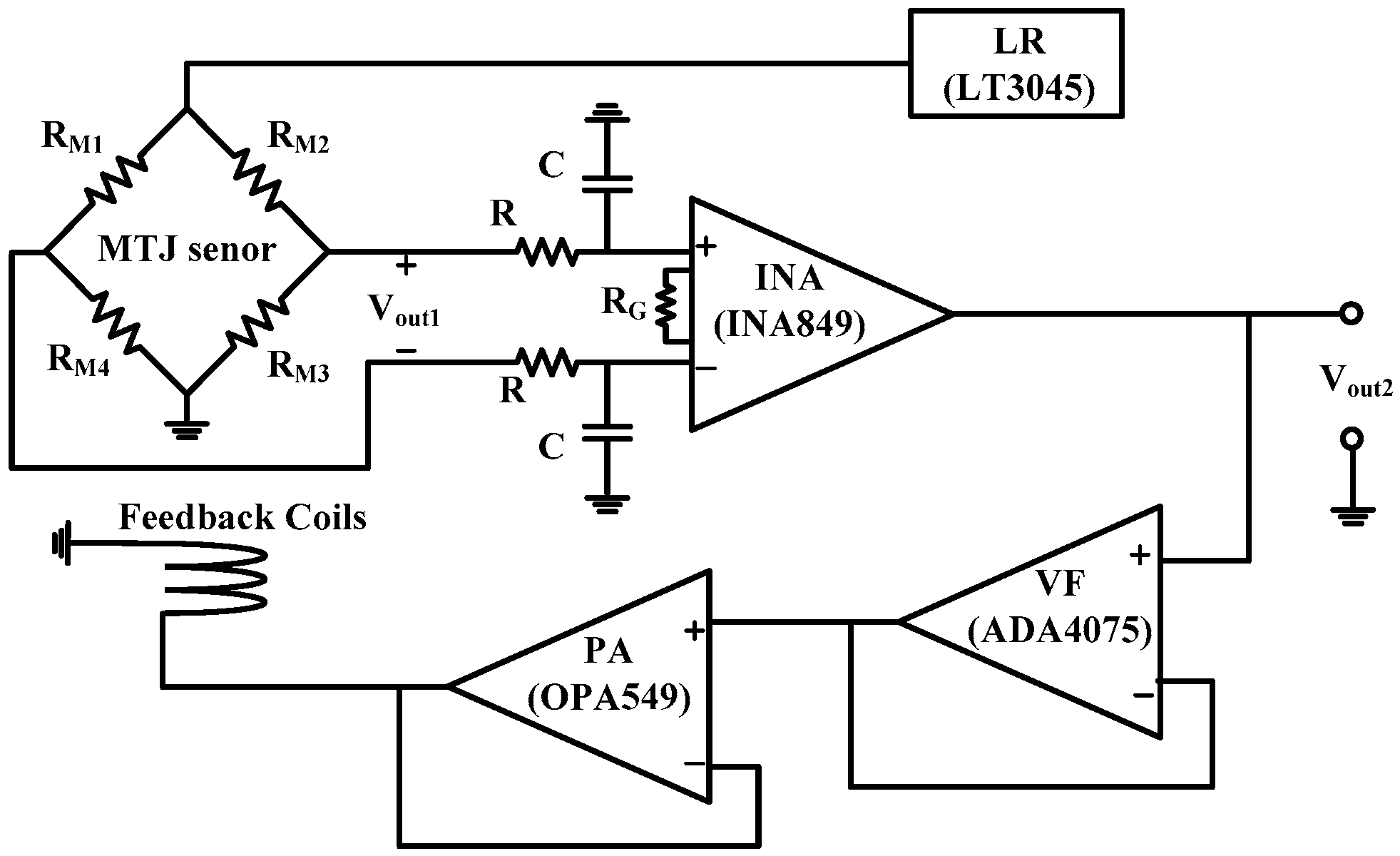
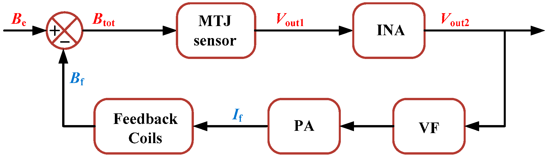
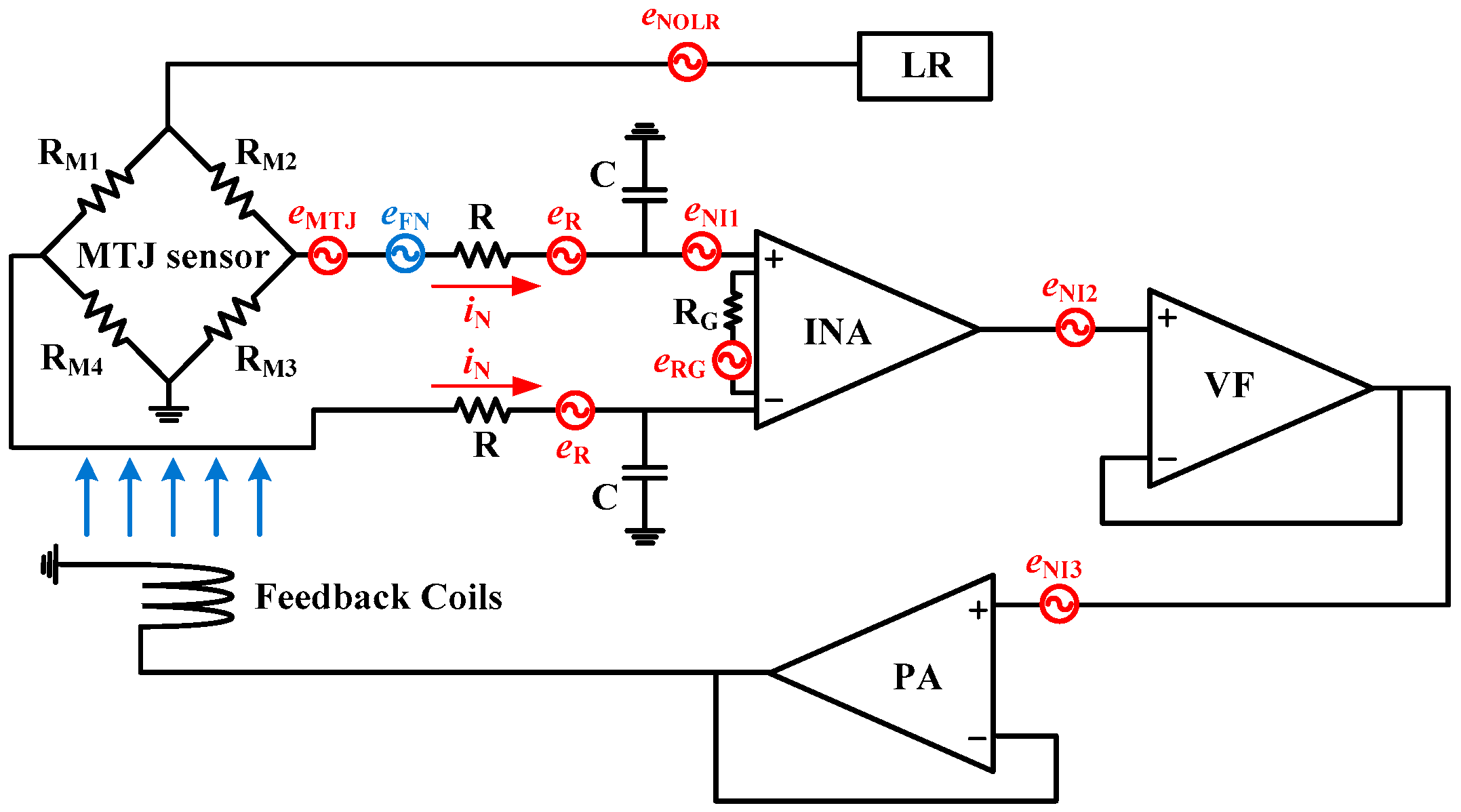
2.2. Design of Signal Conditioning Circuit and Feedback Circuit

The signal conditioning circuit consists of a linear regulator (LR), two RC low-pass filters, an INA, and a voltage follower (VF). The RC low-pass filters are set at the differential output of the MTJ sensor to eliminate the effect of noise above 10 kHz in the magnetometer to avoid system oscillation. The INA is used to read and amplify the differential output voltage signal of the MTJ sensor. To increase the measurement range of the MTJ sensor and improve the linearity of the system, a feedback circuit is provided at the output end of the INA, including a PA and feedback coils. The VF is used as a voltage follower for isolation between the INA and the PA. The voltage gain of the PA is set to 1. The schematic diagram of the MTJ magnetometer with in situ magnetic feedback is shown in Figure 3. Vout1 stands for the MTJ sensor output, and Vout2 stands for the INA output.
Figure 4 shows the basic block diagram of the magnetic feedback principle. Be and Bf denote the external and feedback magnetic fields, respectively.
In this case, the total magnetic field Btot measured by the MTJ sensor is (BeBf). The output Vout2 of the INA will be s1 × G × (BeBf), where G is the gain factor of the INA.
The feedback coils consist of two 5-turn planar spiral coils connected in reverse series to enhance the feedback magnetic field. The width and thickness of each turn in the feedback coils are 0.4 mm and 0.07 mm, respectively. The gap between two adjacent turns of the planar spiral coil is 0.17 mm. The central void in the planar spiral coil is 10 mm × 2 mm. Therefore, the overall size of the feedback coils is 15.36 mm × 14.89 mm. The feedback coils and the MTJ sensor are placed as shown in Figure 5. The sensitive axis of the MTJ sensor is perpendicular to the long side of the feedback coils. The current in the feedback coils has a magnetic field conversion ratio r1 of 6.22 Oe/A at the MTJ sensor through finite element simulation and actual measurement. The feedback coils and the MTJ sensor are connected to the signal conditioning circuit through a detachable flexible printed circuit (FPC) board.
The outputs of the MTJ sensor and the INA in the magnetometer are both measured by varying the external magnetic field from −8 Oe to +8 Oe, as shown in Figure 6.
As seen from the curves, both Vout1 and Vout2 exhibit an excellent linear relationship with the external magnetic field signal in the range of ±8 Oe. Through calculation, the magnetometer with in situ magnetic feedback has a voltage conversion ratio of 0.68 mV/V/Oe at the MTJ sensor (the bias voltage of the MTJ sensor is 1 V). Compared with the curves in Figure 2, the linear operating field range of the MTJ sensor extends from ±0.5 Oe to ±8 Oe, about 15 times higher, demonstrating that the measurement range of the closed-loop magnetometer has been greatly increased. Furthermore, the feedback magnetic field can compensate for 99.409% of the external magnetic field at the MTJ sensor.

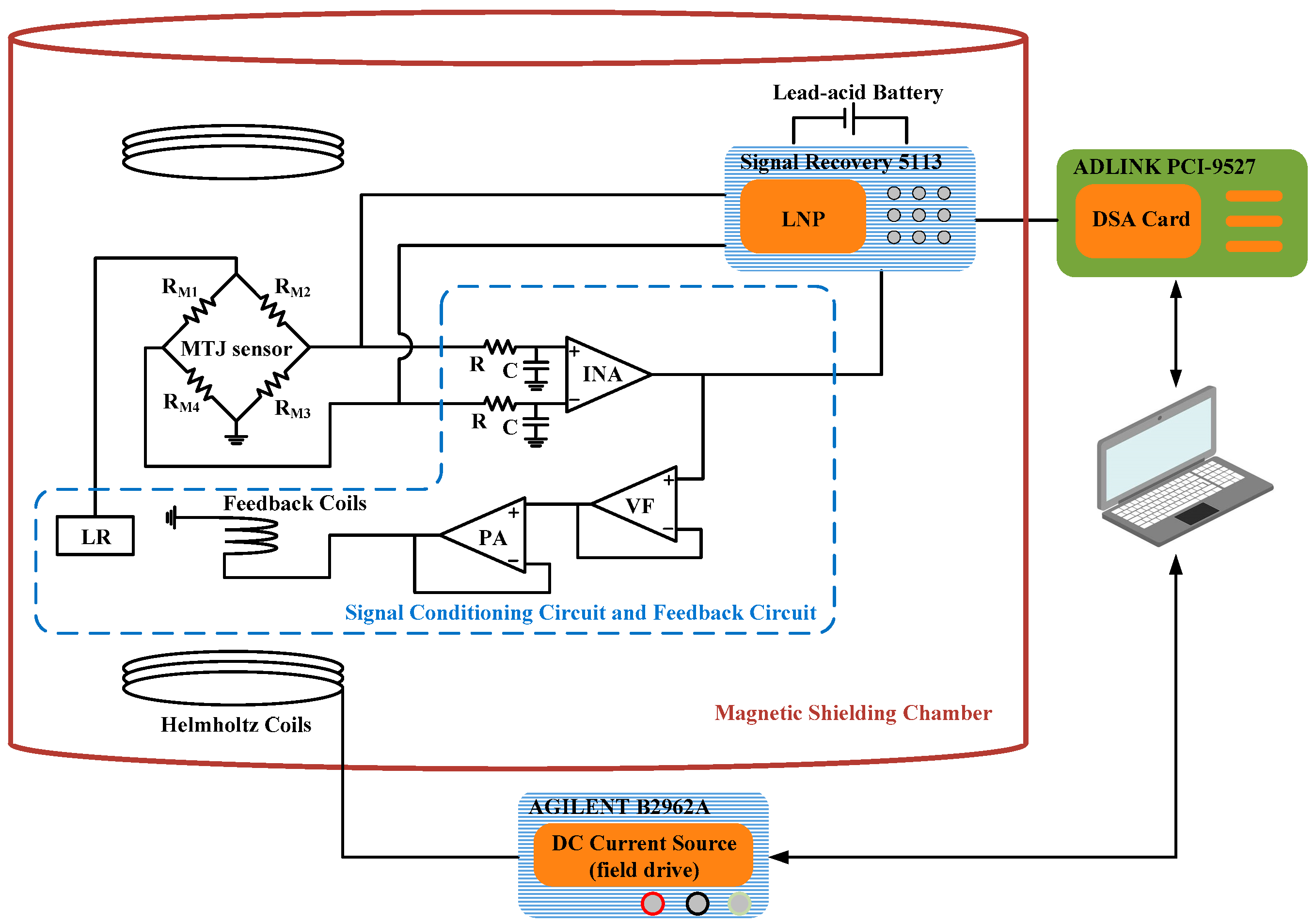
3. Noise Measurement Setup

As shown in Figure 7, the noise measurement system is built using a high-precision dynamic signal acquisition (DSA) card and a low-noise preamplifier (LNP) [26,27,28]. The magnetometer, Helmholtz coils, and LNP are placed in a magnetic shielding chamber for shielding environmental magnetic fields. After demagnetization, the remanence inside the magnetic shielding chamber is less than 1 nT. To reduce the noise introduced by a power supply, the LNP is powered by a lead-acid battery. The noises in Vout1 and Vout2 are collected for different external magnetic fields and compared.
The noise signals generated by the magnetometer are amplified by the LNP with a gain of 40 dB and further sampled by the high-precision DSA card with a sample rate of 400 kHz. The noise voltage spectral density (VSD) is calculated using the fast Fourier transform (FFT) method.
The noise measurement system is calibrated with a commercial metal film resistor whose resistance is 4.73 kΩ, and the precision of the system is about 2% [26].

4. Results and Discussion

4.1. MTJ Sensor Noise Model and Measurement

The noise power at the output of the MTJ sensor is equal to the noise in one bridge arm when the four arms of the Wheatstone bridge have equivalent noise sources [1,20]. The noise of the MTJ sensor consists of thermal-electronic noise, shot noise, thermal-magnetic noise, electronic 1/f noise, and magnetic 1/f noise [1,2,17,20,21,26].
Thermal-electronic noise, also known as Johnson-Nyquist noise, is caused by the random thermal motion of carriers near the Fermi surface affected by temperature [17]. The general expression for this noise power spectral density (PSD) is
S therm-elec MTJ = 4 k B T R MTJ
where kB is the Boltzmann constant, T is the absolute temperature, and RMTJ is the resistance of a single bridge arm in the Wheatstone bridge. The thermal-electronic noise is only related to the resistance value and the ambient temperature. Shot noise arises in discontinuities in the conduction medium as a consequence of the discrete nature of the electrical charge and is described by the following expression [1,20].
S shot MTJ = 2 q I MTJ R MTJ 2 N
where q is the electron electrical charge, IMTJ is the current flowing through each MTJ element, and N is the number of MTJ elements in a single bridge arm. Since the thermal-electronic noise and shot noise are intertwined in tunnel junctions, it is commonly expressed as a combination of the two noises [1,17,20]. A general expression for thermal-shot noise is given as
S therm-shot MTJ = 2 q I MTJ R MTJ 2 N coth q V J 2 k B T
where VJ is the voltage drop across each MTJ element. When the bias voltage is low, qVJkBT, expression (3) is equivalent to thermal-electronic noise. On the other hand, at high bias voltage or low temperature, qVJkBT, expression (3) approaches shot noise.
Thermal-magnetic noise is mainly caused by magnetization fluctuations due to the magnetic field and thermal excitation. Egelhoff et al. [20] proposed a method for calculating the field PSD of thermal-magnetic noise by employing the Gilbert damping parameter and Gyromagnetic ratio. The field PSD is given by
S therm-mag MTJ = 4 k B T μ 0 α G N Ω γ M s
where μ0 is the permeability of free space, αG is the Gilbert damping parameter, Ω is the volume of the free magnetosphere, γ is the gyromagnetic ratio of electrons, and Ms is the saturation magnetization of the free layer.
The electronic 1/f noise occurs as soon as a current is applied to the MTJ sensor. Charge trapping in the barrier or near the layer interface is the source of the electronic 1/f noise [1,17,20]. It is typically written as
S elect 1 / f MTJ = α elect I MTJ 2 R MTJ 2 A f
where αelect is the electronic 1/f Hooge parameter, A is the total area of MTJ elements in a single bridge arm, and f is the frequency.
The magnetic 1/f noise originates from the magnetization hopping between the metastable ripple states [1,20,21]. The field PSD is given by
S mag 1 / f MTJ = 2 B s a t α m a g Ν Ω f
where Bsat is the saturation magnetic induction and αmag is the magnetic 1/f Hooge parameter. Both thermal-magnetic noise and magnetic 1/f noise are magnetically derived noise. However, the significant difference between these two noises is that the latter is frequency-dependent. Thermal-magnetic noise and thermal-shot noise are frequency-independent and can be considered as white noise.
Since the thermal-shot noise, thermal-magnetic noise, electronic 1/f noise, and magnetic 1/f noise are incoherent, the total noise power is the superposition of all the uncorrelated noise sources mentioned above [1,2,20,21,26]. The noise power spectral density (unit of V2/Hz) of the MTJ sensor is described as
S V MTJ = S therm-shot MTJ + S elect 1 / f MTJ + d V d B 2 × S therm-mag MTJ + S mag 1 / f MTJ = 2 q I MTJ R MTJ 2 N coth q V J 2 k B T + α elect I MTJ 2 R MTJ 2 A f + d V d B 2 × 4 k B T μ 0 α G N Ω γ M s + 2 B s a t α m a g Ν Ω f
where dV/dB is the sensitivity of the MTJ sensor.
During noise measurement, the output signal of the MTJ sensor is transmitted to the LNP. When the external magnetic field is zero, the measured noise voltage spectrum of the MTJ sensor without in situ magnetic feedback exhibits a distinct 1/f characteristic, as shown in Figure 8. This is because 1/f noise is dominant in the low-frequency regime [21]. Similar phenomena have been reported by other researchers on noise measurements of MTJ sensors [15,16,26,28].

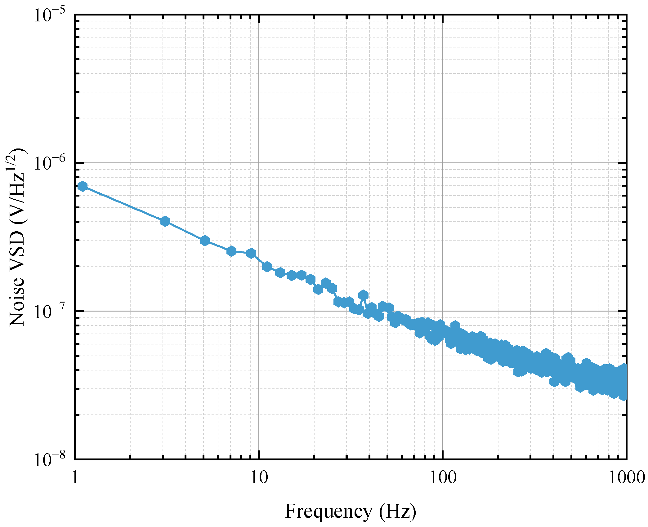
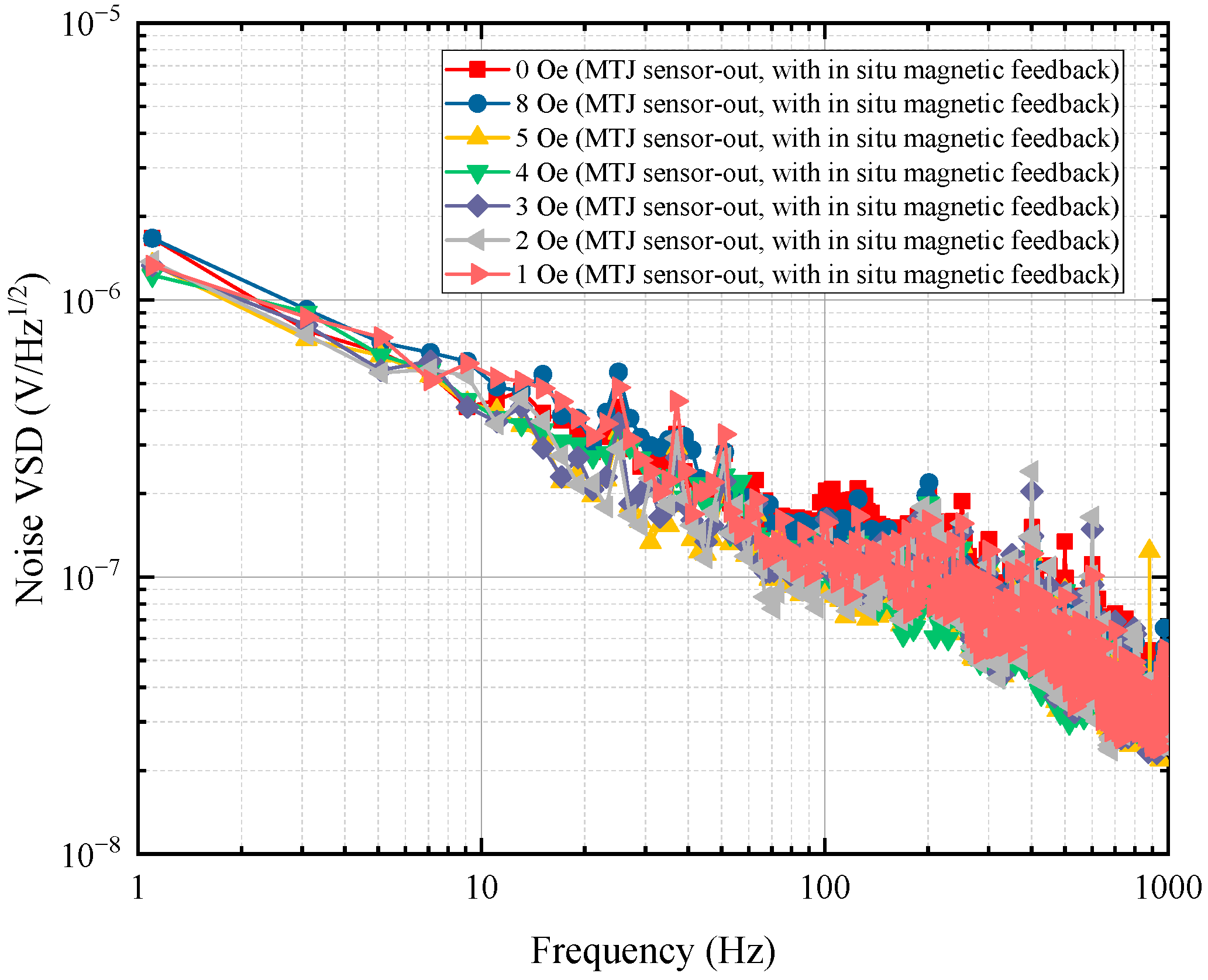
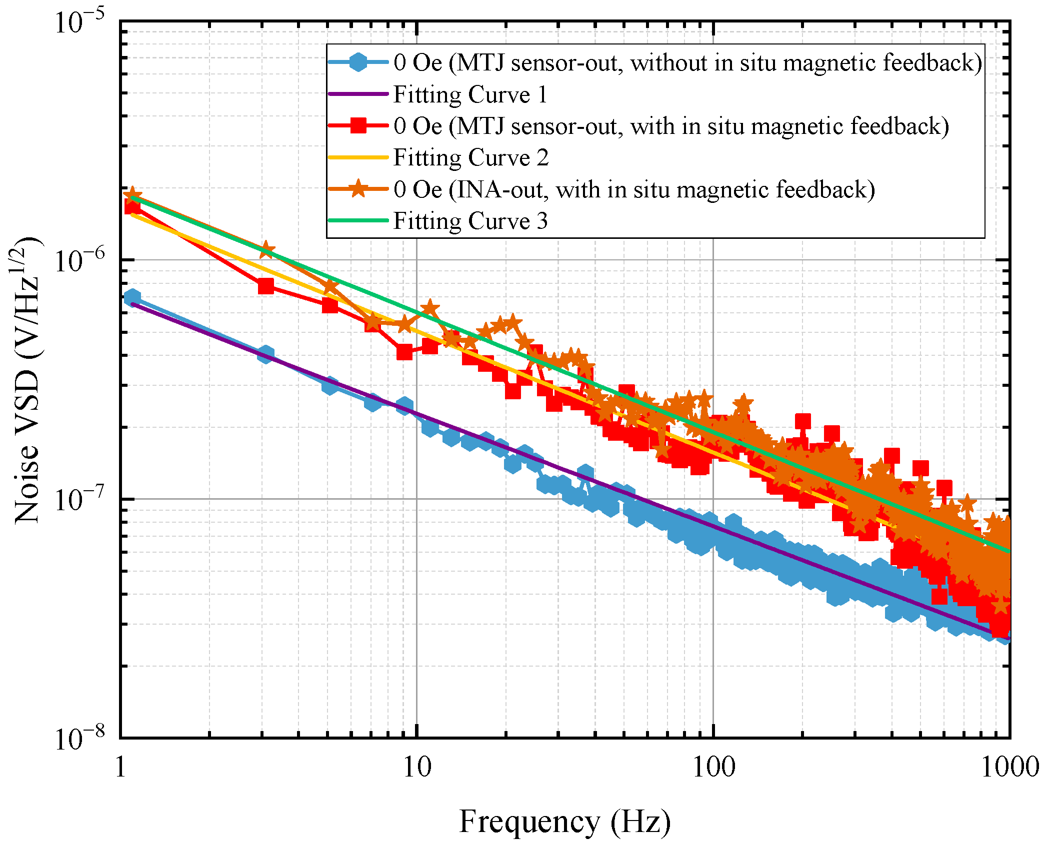
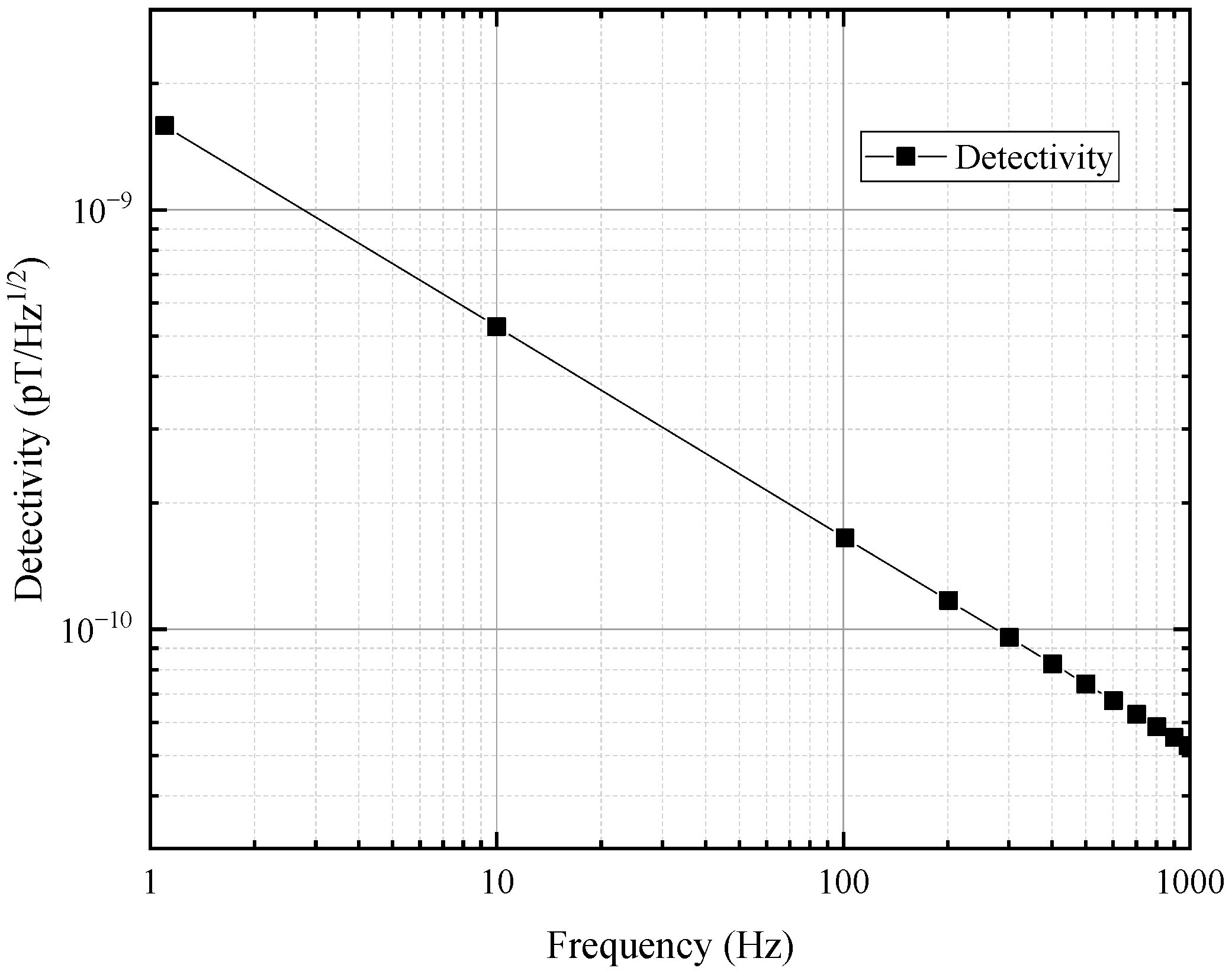
4.2. Magnetometer Noise Model and Measurement

Figure 9 gives an illustrative diagram of the equivalent noise model of the MTJ magnetometer with in situ magnetic feedback. The total noise mainly includes the noise eMTJ from the MTJ sensor, the noise from the signal conditioning circuit, as well as the noise introduced by the feedback coils. The LR generates output voltage noise eNOLR. The resistor in the signal conditioning circuit generates thermal noise eR and eRG. The INA generates input voltage noise eNI1 and current noise iN. The VF generates input voltage noise eNI2. The PA generates input voltage noise eNI3. eFN is the feedback noise transferred from all noise sources to the MTJ sensor through the feedback coils.
To express the referred to input (RTI) noise voltage spectral density of each noise source in Figure 9, the transfer function of the RC low-pass filter needs to be calculated first. The transfer function can be expressed as
H s = 1 1 + s R C
where R and C are the resistance and capacitance used in the low-pass filter, respectively, R is 1 kΩ, C is 15 nF, and s is the complex frequency.
The gain factor (G) of the INA can be obtained directly from its datasheet as follows.
G = 1 + 6   k Ω R G
where RG is the resistance of the resistor used for gain selection. In this magnetometer, RG is set to 43 Ω and G is 140.5.
According to Equations (2) and (3), the RTI noise VSD for all devices is summarized in Table 1.
The feedback noise eFN is correlated with the noise generated by each device in the signal conditioning circuit and feedback circuit, so eFN can be expressed by the following equation:
e FN = c × 2 × e R × H s × G 2 + e RG × G 2 + e NI 1 × G 2 + e NI 2 2 + e NI 3 2 Z 3 × r 1 × s 1
where c is the correlation coefficient between eFN and the noises of devices, and Z3 is the load impedance of PA, which is 0.6 Ω.
The noise characteristics of the integrated circuit (IC) devices in the signal conditioning circuit and the feedback circuit are listed in Table 2, which are cited from their datasheets. eNI denotes input voltage noise, eNO denotes output voltage noise, and iN denotes current noise.
Taking the frequency of 10 Hz as an example, |H (S)| is approximately 1. Based on Figure 7 and Table 2, the referred to input noise VSD of each noise source can be calculated, as shown in Table 3.
It can be seen that the eMTJ is 224 nV/Hz1/2, which is much greater than those of other devices in Table 3.
The noise in the differential output of the MTJ sensor in the magnetometer with in situ magnetic feedback is collected under different external magnetic fields, as shown in Figure 10.
As seen from the curves in Figure 10, the noise in the differential output of the MTJ sensor in the magnetometer with in situ magnetic feedback is almost the same for different external magnetic fields.
The noise voltage spectra of the magnetometer under zero magnetic field are given in Figure 11 and are fitted nonlinearly to obtain the low-frequency noise model. It shows that the noise of the MTJ sensor in the magnetometer with in situ magnetic feedback is obviously higher than the noise of the MTJ sensor in the magnetometer without in situ magnetic feedback.
The fitting relationships are 7.0794 × 10⁻⁷/f0.5008, 1.5948 × 10⁻⁶/f0.4983, and 1.9122 × 10⁻⁶/f0.5006 for curve 1, curve 2, and curve 3, respectively, so the feedback noise eFN is given as follows:
e FN = 1.5948   ×   10 6 f 0.4983 2 7.0794   ×   10 7 f 0.5008 2 14.29   ×   10 7 f 0.5
The eFN is a little more than twice as large as the eMTJ, which indicates that the noise introduced into the MTJ sensor through the feedback coils is the dominant noise source in the magnetometer with in situ magnetic feedback. Furthermore, the correlation coefficient c in Equation (10) can be calculated to be 0.418.
Dividing the measured noise voltage spectrum by the sensitivity of the MTJ sensor yields the detectivity, i.e., the lowest detectable magnetic field. The detectivity of the MTJ magnetometer with in situ magnetic feedback reaches 526 pT/Hz1/2 at a frequency of 10 Hz, as shown in Figure 12.
As can be seen from Figure 9, Figure 10 and Figure 11, the noise of the MTJ magnetometer with in situ magnetic feedback is essentially stable, which is convenient for predicting the detectivity of the magnetometer under different external magnetic fields.

5. Conclusions

In this work, an equivalent noise analysis and modeling method for the MTJ magnetometer with in situ magnetic feedback is presented. Through nonlinear fitting of the noise voltage spectra for the differential output of the MTJ sensor and the output of the INA, it is shown that the noise of the MTJ magnetometer with in situ magnetic feedback exhibits a distinct 1/f characteristic. Among the devices of the magnetometer, the MTJ sensor is the largest noise source. More critically, the noise introduced through the planar spiral feedback coils is twice that of the MTJ sensor. Our results show that although the in situ magnetic feedback in the MTJ magnetometer could improve the characteristics of measurement range and linearity, but also introduce more noise and deteriorate the detectivity of the magnetometer, the design and optimization of the feedback circuit will therefore be key to improving the detectivity of magnetometers with in situ magnetic feedback in the future. For example, the gain of the instrumentation amplifier and the current-to-magnetic field conversion ratio of the feedback coils are critical factors that affect the feedback noise. More research efforts should focus on those two points.

Author Contributions

A.D. and R.B. contributed equally to this work. Conceptualization, A.D., R.B. and Y.S.; methodology, A.D., R.B. and Z.Q.; software, A.D., Y.S. and J.T.; validation, J.T., C.K. and X.X.; formal analysis, A.D. and R.B.; investigation, A.D., R.B. and Y.S.; resources, R.B. and Z.Q.; data curation, J.T., C.K. and X.X.; writing—original draft preparation, A.D. and R.B.; writing—review and editing, A.D., R.B. and Z.Q.; visualization, A.D. and R.B.; supervision, R.B. and Z.Q.; project administration, A.D. and R.B.; funding acquisition, R.B. and Z.Q. All authors have read and agreed to the published version of the manuscript.

Funding

This research was funded by the Fundamental Research Funds for the Provincial Universities of Zhejiang of China (Grant No. GK229909299001-05), the National Key Research and Development Program of China (Grant No. 2018YFF01010701), and the Zhejiang Province Public Welfare Projects of China (Grant No. LGG22F030017).

Institutional Review Board Statement

Not applicable.

Informed Consent Statement

Not applicable.

Data Availability Statement

Not applicable.

Conflicts of Interest

The authors declare no conflict of interest.

References

  1. Yan, S.; Zhou, Z.; Yang, Y.; Leng, Q.; Zhao, W. Developments and Applications of Tunneling Magnetoresistance Sensors. Tsinghua Sci. Technol. 2022, 27, 443–454. [Google Scholar] [CrossRef]
  2. Zheng, C.; Zhu, K.; de Freitas, S.C.; Chang, J.-Y.; Davies, J.E.; Eames, P.; Freitas, P.P.; Kazakova, O.; Kim, C.; Leung, C.-W.; et al. Magnetoresistive Sensor Development Roadmap (Non-Recording Applications). IEEE Trans. Magn. 2019, 55, 0800130. [Google Scholar] [CrossRef]
  3. Yang, S.; Zhang, J. Current Progress of Magnetoresistance Sensors. Chemosensors 2021, 9, 211. [Google Scholar] [CrossRef]
  4. Willing, S.; Schlage, K.; Bocklage, L.; Ramin Moayed, M.M.; Gurieva, T.; Meier, G.; Rohlsberger, R. Novel Tunnel Magnetoresistive Sensor Functionalities via Oblique-Incidence Deposition. ACS Appl. Mater. Interfaces 2021, 13, 32343–32351. [Google Scholar] [CrossRef]
  5. Lim, B.; Mahfoud, M.; Das, P.T.; Jeon, T.; Jeon, C.; Kim, M.; Nguyen, T.-K.; Tran, Q.-H.; Terki, F.; Kim, C. Advances and key technologies in magnetoresistive sensors with high thermal stabilities and low field detectivities. APL Mater. 2022, 10, 51108. [Google Scholar] [CrossRef]
  6. Maciel, N.; Marques, E.; Naviner, L.; Zhou, Y.; Cai, H. Magnetic Tunnel Junction Applications. Sensors 2020, 20, 121. [Google Scholar] [CrossRef]
  7. Nicolas, H.; Sousa, R.C.; Mora-Hernández, A.; Prejbeanu, I.-L.; Hebrard, L.; Kammerer, J.-B.; Pascal, J. Conditioning Circuits for Nanoscale Perpendicular Spin Transfer Torque Magnetic Tunnel Junctions as Magnetic Sensors. IEEE Sens. J. 2023, 23, 5670–5680. [Google Scholar] [CrossRef]
  8. Bai, R.; Qian, Z.; Zhu, H.; Li, Q.; Li, Y.; Peng, Y.; Huo, D. Effect of Buffer Layers on the Properties of NiFe/Cu/NiFe Trilayers. IEEE Trans. Magn. 2017, 53, 4400104. [Google Scholar] [CrossRef]
  9. Qian, Z.; Wang, D.; Daughton, J.; Tondra, M.; Nordman, C.; Popple, A. Linear Spin-Valve Bridge Sensing Devices. IEEE Trans. Magn. 2004, 40, 2643–2645. [Google Scholar] [CrossRef]
  10. García Vidal, E.; Ramírez Muñoz, D.; Ravelo Arias, S.I.; Sánchez Moreno, J.; Cardoso, S.; Ferreira, R.; Freitas, P. Electronic Energy Meter Based on a Tunnel Magnetoresistive Effect (TMR) Current Sensor. Materials 2017, 10, 1134. [Google Scholar] [CrossRef]
  11. Ziegler, S.; Woodward, R.C.; Iu, H.H.-C.; Borle, L.J. Current Sensing Techniques: A Review. Current Sensing Techniques: A Review. IEEE Sens. J. 2009, 9, 354–376. [Google Scholar] [CrossRef]
  12. Yu, J.; Long, Z.; Liang, S.; Yue, C.; Yin, X.; Zhou, F. Optimal design of dual air-gap closed-loop TMR current sensor based on minimum magnetic field uniformity coefficient. Sci. Rep. 2023, 13, 239. [Google Scholar] [CrossRef] [PubMed]
  13. Sen, T.; Sreekantan, A.C.; Sen, S. A Magnetic Feedback-Based Δ–Σ Digitizing Interface for Giant Magnetoresistance Sensors. IEEE Trans. Circuits Syst. 2023, 70, 36–40. [Google Scholar] [CrossRef]
  14. Bernieri, A.; Betta, G.; Ferrigno, L.; Laracca, M. Improving Performance of GMR Sensors. IEEE Sens. J. 2013, 13, 4513–4520. [Google Scholar] [CrossRef]
  15. Davies, J.E.; Watts, J.D.; Novotny, J.; Huang, D.; Eames, P.G. Magnetoresistive sensor detectivity: A comparative analysis. Appl. Phys. Lett. 2021, 118, 062401. [Google Scholar] [CrossRef]
  16. Monteblanco, E.; Solignac, A.; Chopin, C.; Moulin, J.; Belliot, P.; Belin, N.; Campiglio, P.; Fermon, C.; Pannetier-Lecoeur, M. Normalization and Correction Factors for Magnetic Tunnel Junction Sensor Performances Comparison. IEEE Sens. J. 2021, 21, 15993–15998. [Google Scholar] [CrossRef]
  17. Weitensfelder, H.; Brueckl, H.; Satz, A.; Pruegl, K.; Zimmer, J.; Luber, S.; Raberg, W.; Abert, C.; Bruckner, F.; Bachleitner-Hofmann, A.; et al. Comparison of Sensitivity and Low-Frequency Noise Contributions in Giant-Magnetoresistive and Tunneling-Magnetoresistive Spin-Valve Sensors with a Vortex-State Free Layer. Phys. Rev. Appl. 2018, 10, 054056. [Google Scholar] [CrossRef]
  18. Zhang, X.; Ji, M.; Pan, M.; Sun, K.; Hu, Y.; Du, Q.; Li, P.; Peng, J.; Hu, J.; Qiu, W. Effective measurement of magnetic tunneling junction noise based on the equivalent noise model. J. Magn. Magn. Mater. 2023, 580, 170930. [Google Scholar] [CrossRef]
  19. Yuan, Z.H.; Feng, J.F.; Guo, P.; Wan, C.H.; Wei, H.X.; Ali, S.S.; Han, X.F.; Nakano, T.; Naganuma, H.; Ando, Y. Low frequency noise in magnetic tunneling junctions with Co40Fe40B20/Co70.5Fe4.5Si15B10 composite free layer. J. Magn. Magn. Mater. 2016, 398, 215–219. [Google Scholar] [CrossRef]
  20. Egelhoff, W.; Pong, P.; Unguris, J.; McMichael, R.; Nowak, E.; Edelstein, A.; Burnette, J.E.; Fischer, G.A. Critical challenges for picoTesla magnetic-tunnel-junction sensors. Sens. Actuators A Phys. 2009, 155, 217–225. [Google Scholar] [CrossRef]
  21. Lyu, H.; Liu, Z.; Wang, Z.; Yang, W.; Xiong, X.; Chen, J.; Zou, X. A high-resolution MEMS magnetoresistive sensor utilizing magnetic tunnel junction motion modulation driven by the piezoelectric resonator. Appl. Phys. Lett. 2022, 121, 123504. [Google Scholar] [CrossRef]
  22. Nakatani, T.; Suto, H.; Kulkarni, P.D.; Iwasaki, H.; Sakuraba, Y. Tunnel magnetoresistance sensors with symmetric resistance-field response and noise properties under AC magnetic field modulation. Appl. Phys. Lett. 2022, 121, 192406. [Google Scholar] [CrossRef]
  23. Jin, Z.; Wang, Y.; Fujiwara, K.; Oogane, M.; Ando, Y. Detection of Small Magnetic Fields Using Serial Magnetic Tunnel Junctions with Various Geometrical Characteristics. Sensors 2020, 20, 5704. [Google Scholar] [CrossRef]
  24. Gao, J.; Wang, J.; Shen, Y.; Jiang, Z.; Huang, Y.; Yu, Q. Equivalent Magnetic Noise Analysis for a Tunneling Magnetoresistive Magnetometer. IEEE Electron Device Lett. 2020, 41, 1400–1403. [Google Scholar] [CrossRef]
  25. Du, Q.; Hu, J.; Pan, M.; Chen, D.; Sun, K.; Pan, L.; Che, Y.; Zhang, X.; Li, P.; Zhang, J.; et al. Effect of magnetic flux modulation on noise characteristics of tunnel magnetoresistive sensors. Appl. Phys. Lett. 2020, 116, 102405. [Google Scholar] [CrossRef]
  26. Dou, A.; Bai, R.; Zhu, H.; Qian, Z. Noise measurement and system calibration on magnetoresistive sensors. Sens. Rev. 2023, 43, 200–207. [Google Scholar]
  27. Roldán, A.; Roldán, J.B.; Reig, C.; Cardoso, S.; Cardoso, F.; Ferreira, R.; Freitas, P.P. An in-depth noise model for giant magnetoresistance current sensors for circuit design and complementary metal-oxide-semiconductor integration. J. Appl. Phys. 2014, 115, 17E514. [Google Scholar] [CrossRef]
  28. Stutzke, N.A.; Russek, S.E.; Pappas, D.P.; Tondra, M. Low-frequency noise measurements on commercial magnetoresistive magnetic field sensors. J. Appl. Phys. 2005, 97, 10Q107. [Google Scholar] [CrossRef]
Figure 1. Transfer curve measurement system.
Magnetochemistry 09 00214 g001
Figure 2. Output and sensitivity of the MTJ sensor.
Magnetochemistry 09 00214 g002
Figure 3. Schematic diagram of the MTJ magnetometer with in situ magnetic feedback.
Magnetochemistry 09 00214 g003
Figure 4. Basic block diagram of the magnetic feedback principle.
Magnetochemistry 09 00214 g004
Figure 5. Schematic of the planar spiral feedback coils and MTJ sensor (arrow shows the sensing direction).
Magnetochemistry 09 00214 g005
Figure 6. Outputs of the magnetometer.
Magnetochemistry 09 00214 g006
Figure 7. Illustration of the noise measurement setup.
Magnetochemistry 09 00214 g007
Figure 8. Measured noise voltage spectrum of MTJ sensor without in situ magnetic feedback at H = 0 Oe.
Magnetochemistry 09 00214 g008
Figure 9. Noise sources in the magnetometer.
Magnetochemistry 09 00214 g009
Figure 10. Noise spectrum comparison of the magnetometer with in situ magnetic feedback under different external magnetic fields.
Magnetochemistry 09 00214 g010
Figure 11. Noise spectra of the magnetometer with and without in situ magnetic feedback at H = 0 Oe.
Magnetochemistry 09 00214 g011
Figure 12. Detectivity vs. frequency for the magnetometer with in situ magnetic feedback at H = 0 Oe.
Magnetochemistry 09 00214 g012
Table 1. The RTI noise VSD for all noise sources.
Noise SourceNoise TypeRTI Noise VSD
(V/Hz1/2)
MTJ sensorthermal-shot noiseeMTJ
thermal-magnetic noise
1/f noise
LR (LT3045)output voltage noise—eNOLReNOLR
Low-pass filterthermal noise—eR 4 k B T R
INA
(INA849)
input voltage noise—eNI1 e NI 1 H s
current noise—iN i N   ×   Z 1 H s , i N   ×   Z 2 H s
thermal noise—eRG 4 k T R G H s
VF
(ADA4075-2)
input voltage noise—eNI2 e NI 2 H s   ×   G
PA
(OPA549)
input voltage noise—eNI3 e NI 3 H s   ×   G
Feedback Noisemagnetic noise—eFNeFN
where Z1 = RM2 × RM3/(RM2 + RM3) + R, Z2 = RM1 × RM4/(RM1 + RM4) + R.
Table 2. Noise characteristics of the IC devices at 10 Hz.
DeviceeNI
(nV/Hz1/2)
eNO
(nV/Hz1/2)
iN
(fA/Hz1/2)
LT3045 70
INA8493 3
ADA4075-23.5
OPA549120
Table 3. The calculated RTI noise VSD of each noise source.
Noise SourceNoise TypeCalculated RTI Noise VSD
(nV/Hz1/2)
MTJ sensorthermal-shot noise224
thermal-magnetic noise
1/f noise
LR(LT3045)output voltage noise—eNOLR70
Low pass filterthermal noise—eR4
INA
(INA849)
input voltage noise—eNI13
current noise—iN0.08
thermal noise—eRG0.8
VF
(ADA4075-2)
input voltage noise—eNI20.02
Disclaimer/Publisher’s Note: The statements, opinions and data contained in all publications are solely those of the individual author(s) and contributor(s) and not of MDPI and/or the editor(s). MDPI and/or the editor(s) disclaim responsibility for any injury to people or property resulting from any ideas, methods, instructions or products referred to in the content.

