Article

Research on Electromagnetic Radiation Characteristics of Energetic Materials

School of Mechanical Engineering, Nanjing University of Science and Technology, Nanjing 210094, China
*
Authors to whom correspondence should be addressed.
Magnetochemistry 2022, 8(5), 57; https://doi.org/10.3390/magnetochemistry8050057
Submission received: 27 February 2022 / Revised: 14 May 2022 / Accepted: 18 May 2022 / Published: 20 May 2022

Abstract

:
During the explosion of energetic materials, electromagnetic interference is generated, which can affect the normal operation of surrounding electronic equipment. Therefore, an electromagnetic radiation measurement device based on a short-wave omnidirectional antenna and ultra-wideband omnidirectional antenna was designed to measure the electromagnetic radiation generated by the explosion of energetic materials of different masses, and the electromagnetic radiation characteristics were obtained through data processing. The results showed that the electromagnetic signal can still be collected hundreds of milliseconds after the explosive is detonated, and the electromagnetic radiation generated by the explosion is continuous and intermittent, which is a phenomenon that has not been found in this field at present. The mass of the energetic material had a significant effect on the time-domain characteristics of the electromagnetic radiation generated by the explosion: the higher the mass of the energetic material was, the shorter the delay response of the electromagnetic signal was, the longer the duration was, and the earlier the peak appeared. The frequency of electromagnetic radiation signals generated by the explosion of energetic materials was mainly concentrated below 100 MHz, and the energy was most concentrated in the frequency band of 0~50 MHz. The composition of energetic materials had the greatest influence on the spectral distribution, and the spectral distribution of electromagnetic radiation produced by the explosion of explosives with different compositions had obvious specificity. The electromagnetic radiation intensity generated by the explosion of energetic materials had a strong correlation with the distance from the explosion center, and it significantly decreased as the distance increased. The structure and detonation method of energetic materials changed the geometrical motion pattern during the explosion, resulting in the non-uniformity of electromagnetic radiation propagation.

1. Introduction

An explosion of energetic materials produces strong electromagnetic radiation. Electromagnetic radiation of different intensities or frequencies can cause electromagnetic interference in nearby electronic equipment, such as unmanned aerial vehicles and communication devices, and, in severe cases, the equipment cannot be operated or is damaged, resulting in an accident. In order to improve the anti-electromagnetic-interference performance of electronic equipment, it is necessary to measure and study the electromagnetic radiation generated by the explosion of energetic materials [1].
In 1954, Kolsky published an article on the measurements of electromagnetic waves emitted from the detonation of high-explosives charges [2]. Boronin studied the physical mechanisms of the electromagnetic wave generated by the explosion of condensed explosives. Boronin believed that at the initial moment of metal deformation and destruction, gaseous and solid potential energy flowed out of the formed cracks. Due to the electrokinetic effect and the friction of the potential energy on the failed shell, the shell is charged, and the charged polarity of the gas and the solid are opposite. Due to the asymmetric scattering of the potential energy, the space charge of the potential energy of the gas and the solid forms an effective dipole. Boronin proposed that the mechanism of electromagnetic radiation produced by explosion was related to the acceleration or deceleration of certain electronic in the ionized air layer at the front of shock wave, which was later called the “Boronin effect” [3,4]. Boronin first described the mechanism of electromagnetic radiation generated during the explosion of energetic materials, which guided the direction of related research in the future. A.L. Kuhl explained the mechanism of electromagnetic waves generated by TNT; he believed that the movement of ionized atoms, ions, and electrons was the cause of explosive electromagnetic waves. The expansion of detonation products caused strong vibrations in the surrounding air and formed a strong heat wave that lasted approximately 20 μs. Temperatures as high as 11,000 K cause significant ionization in the air, and the movement of ion plaques generates electric currents that then generate electric and magnetic fields. Kuhl studied the effects of these motions through numerical simulations of TNT explosions, using high-order Godunov equations to integrate the conservation laws of one-dimensional aerodynamics, and using a very fine grid (minimum unit as 10 μm) to obtain the convergent temperature and the conductivity profile, which was then used to predict the three-dimensional electromagnetic waves generated by TNT explosions [5,6,7]. Li Jianqiao conducted theoretical and numerical simulation studies on the natural magnetic field disturbance caused by the explosion of energetic materials, obtained the temporal and spatial distribution of the electrical conductivity and the magnetic field diffusion rate of the explosive field, and found that the explosive initiation parameters had a significant influence on the magnetic field disturbance. Li Jianqiao developed a more reliable method for the numerical simulation of magnetic field disturbances in explosive fields and pointed out that when explosives were geometrically asymmetric, different magnetic field disturbances would be generated in different directions of the natural magnetic field through numerical simulations. Different types of energetic materials have different amplitudes of magnetic field disturbance, but the disturbance mode is the same, and this research has been overlooked in related fields despite its usefulness [8,9]. Ren Huilan and Chen Hong measured the electromagnetic radiation in their experiments on B explosive and RDX-based aluminum-containing explosives, respectively. Their research results showed that the electromagnetic radiation signal spectrum generated by the explosions of 4.5~7.5 kg of B explosive was mainly distributed in the range of 0~50 kHz, and the amplitude of the first pulse was basically linear to one-third equivalent power; its arrival time was not sensitive to the amount of explosives used. The intensity of the electromagnetic radiation signal generated by an explosion of 160~188 g RDX-based aluminum-containing explosive was in the range of 1.87~15.20 V/m, and the spectrum distribution of electromagnetic radiation was mainly concentrated in the range of 500 MHz, while the content of aluminum in the explosive had an obvious effect on the spectrum distribution of 100~500 MHz [10,11].
In this study, we used a dual-frequency antenna to measure electromagnetic waves and a high-speed acquisition card to record data. The electromagnetic signal was analyzed in detail using methods of noise reduction, Fourier transform, and attenuation compensation. The time-domain and frequency-domain variation characteristics of electromagnetic radiation produced by explosions were discussed, and a more comprehensive and accurate law of electromagnetic radiation was proposed.

2. Experimental Principle and Method

2.1. Experimental Principle

Measuring electromagnetic radiation generated by explosive required the consideration of factors such as electromagnetic radiation intensity, propagation law and direction, equivalent testing, and antenna device protection in the explosive field. According to the theory of explosion mechanics and electromagnetics, assuming f is the characteristic time, f = t / m 1 / 3 , where m is the quantity of explosive, the relationship between the velocity of the gas explosion product u(f), the velocity of the solid particles in the explosion product v(f), and the shell fragment velocity u can be expressed as:
u ( f ) = d R ( f ) d f
v ( f ) = u ( 0 ) exp ( B f ) + B · exp [ B f 0 f u ( f ) e B f d f ]
u = D 2 { 1 2 U + 1 [ 1 ( r 0 r ) 4 ] } 1 / 2
B = 9 5 Z a 2 m 1 / 3 , u = M c m
where R(f) is the radius of the contact surface between the gas explosion product and the shell, R ( f ) = 1 + 4.6 × 10 4 f 0.57 × 10 8 f 2 + 3.3 × 10 10 f 3 10 13 f 4 + 1.2 × 10 15 f 5 , D is the explosive speed, Mc is the explosive shell weight, U is the ratio of explosive shell weight to explosive weight, and u(0) is the velocity of the gas explosion product at the initial moment. In Equation (4), a is the radius of solid particle, d is the particle density, and Z is the viscosity coefficient. According to the characteristics of the condensed explosive, 2 μm ≤ a ≤ 5 μm, d ≈ 2 g/cm3, when the quantity of working conditions is constant, B can be considered as a constant. In Equation (3), r0 is the charging radius, r is the limit expansion radius of the charging shell during explosion; Equation (3) becomes u D 2 ( 1 2 U + 1 ) 1 / 2 when ignoring (r0/r)4. Therefore, when studying the electromagnetic radiation of energetic materials, as long as the parameters of m, Mc, f, B, and D are considered, u(f), v(f), and u are considered equivalently. In electromagnetism, E = q 4 π ε r 2 when measuring the electromagnetic radiation of energetic materials, the electric field intensity E, the dielectric constant of air ε, and the distance between antenna and explosion center r must be considered [12,13,14,15,16].

2.2. Experimental Method

According to the theoretical analysis of blasting mechanics, combined with the quantity of explosives used in the experiment, an electromagnetic radiation measuring device was designed, which is shown as Figure 1a. The test point consisted of a short-wave passive omnidirectional antenna, an ultra-wideband passive omnidirectional antenna, a signal amplifier, and a limiter. The short-wave passive omnidirectional antenna was a monopole antenna with a height of 2000 mm, a sampling frequency of 1–30 MHz, and the output impedance was 50 Ω. The ultra-wideband omnidirectional antenna was a dipole antenna with a height of 450 mm and a sampling frequency of 30–1.5 GHz; the output impedance was 50 Ω. The signal conditioner possessed multiple functions including a combiner, a signal amplifier, and a limiter, which can combine two electromagnetic signals of different frequencies and amplify the signal at the same time with a range of amplification factors of 10–30 dB. The function of the limiter with limiting power greater than 10 W was to prevent the signal power from being excessively high and damaging the acquisition card. The test point was connected to the data acquisition card through wideband coaxial cable, and the high-speed acquisition card was used to record the data. The maximum sampling rate was set to 3 GSa/s, the electromagnetic signal with the highest frequency of 1.5 GHz was collected on the basis of the Nyquist sampling law, which matched the frequency bandwidth of the antenna. The sampling duration was set to 810 ms, so the sampling duration before the trigger was 10 ms, and the sampling duration after the trigger was 800 ms [17,18,19,20,21]. As shown in Figure 1b, there were six test points in the distribution diagram. Points 1, 2, and 3 formed Line 1, which were, respectively, 20, 35, and 50 m away from the explosion center. Points 4, 5, and 6 formed Line 2; the distance from the explosion center was 20, 35, and 50 m, respectively. The angle between Line 1 and Line 2 was 60 degrees. The measuring equipment was placed according to the distribution shown in Figure 1b, and the electromagnetic radiation measurement experiment field is shown in Figure 1c.

3. Experimental Results and Analysis

This study measured the electromagnetic radiation of 30 kg and 60 kg TNT explosions, and the experimental process for the explosion of energetic material is shown in Figure 2. Prior to the start of the experiment, the electromagnetic background noise of the experimental site was tested. The maximum voltage of the background electromagnetic signal was 62.5 mV, and the average voltage was 12.531 mV. The electromagnetic signal waveform was stable without fluctuation. Therefore, the electromagnetic noise interference of the experimental site was extremely weak, and the explosion electromagnetic radiation experiment could be conducted.

3.1. Analysis of the Time-Domain Characteristics of Electromagnetic Radiation

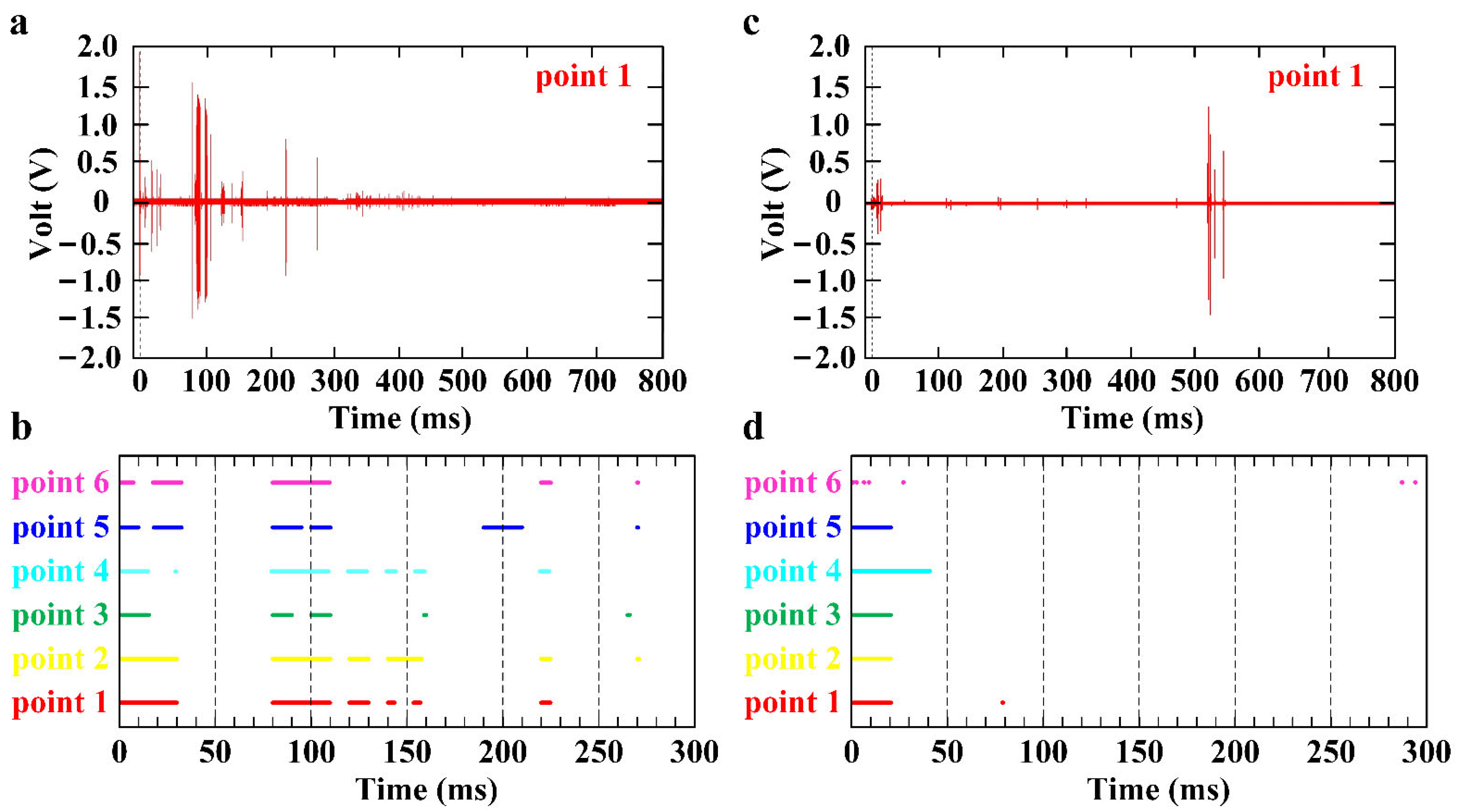
The time-domain characteristics of electromagnetic radiation included parameters such as the duration of the sampling period, the delay response time, and the peak arrival time [22]. In this study, a total of two effective experiments were carried out, and the electromagnetic signals of 30 kg and 60 kg TNT explosives were measured, respectively. Each group of experiments included the signals of six channels, and each channel corresponds to the test points 1–6. The electromagnetic radiation signal generated by the explosion of 60 kg TNT is shown in Figure 3a, and the time-domain distribution of the electromagnetic signal of each adopted channel is shown in Figure 3b. The electromagnetic radiation signal generated by the explosion of 30 kg TNT is shown in Figure 3c, and the time-domain distribution of the electromagnetic signal of each adopted channel is shown in Figure 3d. As shown in Figure 3, the time-domain distribution of the 60 kg TNT electromagnetic pulse was denser, which indicated that the mass of the energetic material had an important influence on the duration of the electromagnetic radiation generated by the explosion. The greater the mass, the longer the duration of the electromagnetic signal. The time-domain distribution of the electromagnetic signals measured by each test point was regular, the electromagnetic signal measured by the test points far from the explosion center had a shorter duration, and the time domain distribution of the electromagnetic pulse was also scattered.
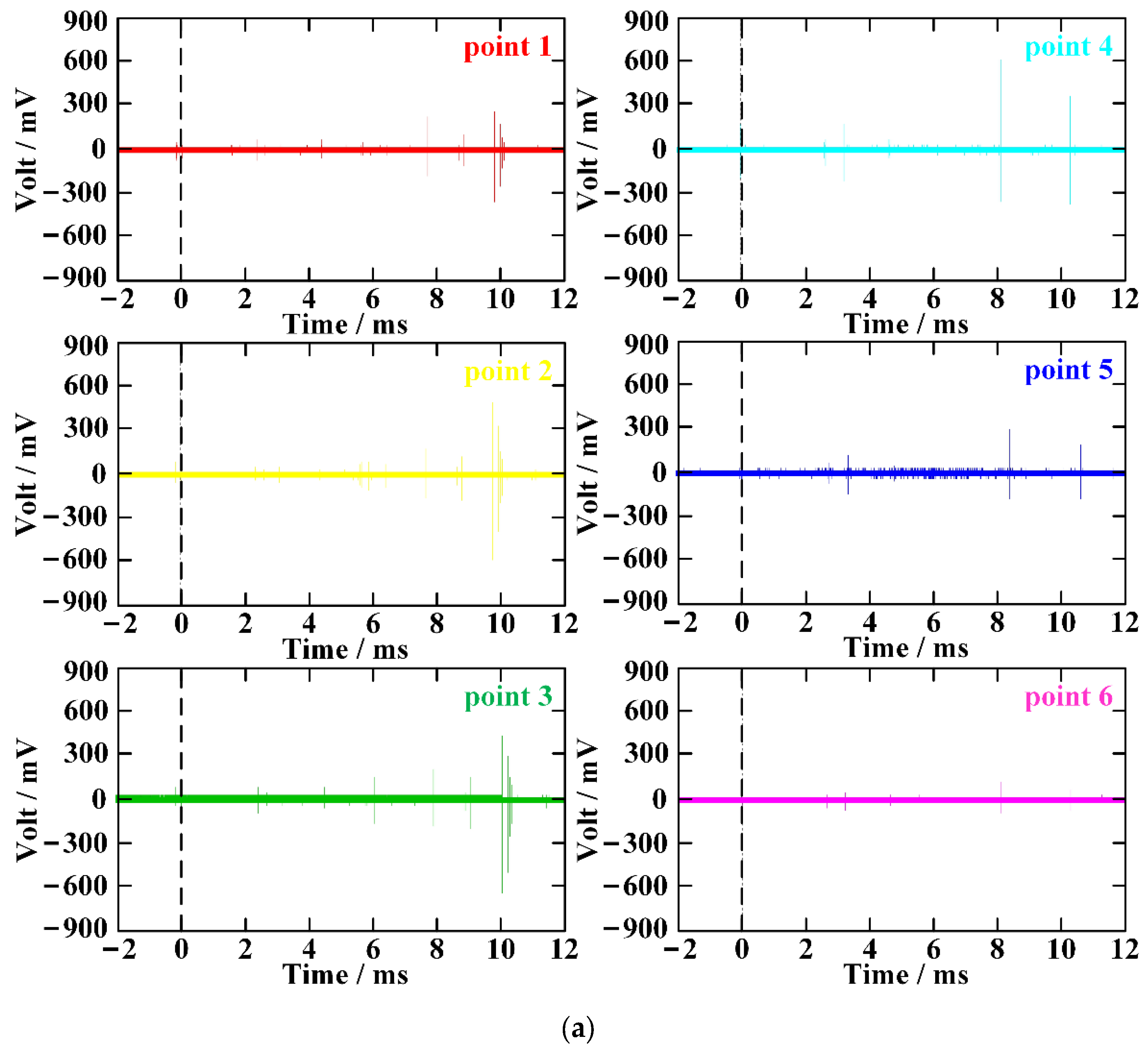
The delay of the electromagnetic radiation signal generated by the explosion of 30 kg TNT is shown in Figure 4a,b, and the delay of the electromagnetic radiation signal generated by the explosion of 60 kg TNT is shown in Figure 4c,d. As shown in Figure 4, the electromagnetic signal of 60 kg TNT appeared significantly earlier than that of 30 kg TNT, the duration of the electromagnetic signal generated by the explosion of 60 kg TNT was also significantly longer than that of 30 kg TNT, and the peak time of the electromagnetic signal generated by the explosion of 60 kg TNT was significantly earlier than that of 30 kg TNT.
The electromagnetic radiation signal produced by the explosion of 30 kg TNT had a large-amplitude electromagnetic pulse appeared around 9.8 ms. The signal delay response time of each test point was not much different, and the test point far from the explosion center had a slightly later signal appearance time. The arrival time of the electromagnetic radiation signal generated by the 60 kg TNT explosion was concentrated between 46 μs and 62 μs after the trigger. At the same distance, the electromagnetic signal appearance time of the test point on testing line 2 was 5–10 μs delayed than that of the test point on testing line 1, and the peak appearance time of the electromagnetic signal measured by most of the test points was between 0.31 ms and 0.39 ms. The mass of the energetic materials had a significant impact on the time-domain characteristics of the electromagnetic radiation produced by the explosion. For energetic materials of the same quantity, the type and composition of explosives should not have a significant effect on the time-domain characteristics of electromagnetic radiation generated by the explosion.

3.2. Analysis of the Frequency-Domain Characteristics of Electromagnetic Radiation

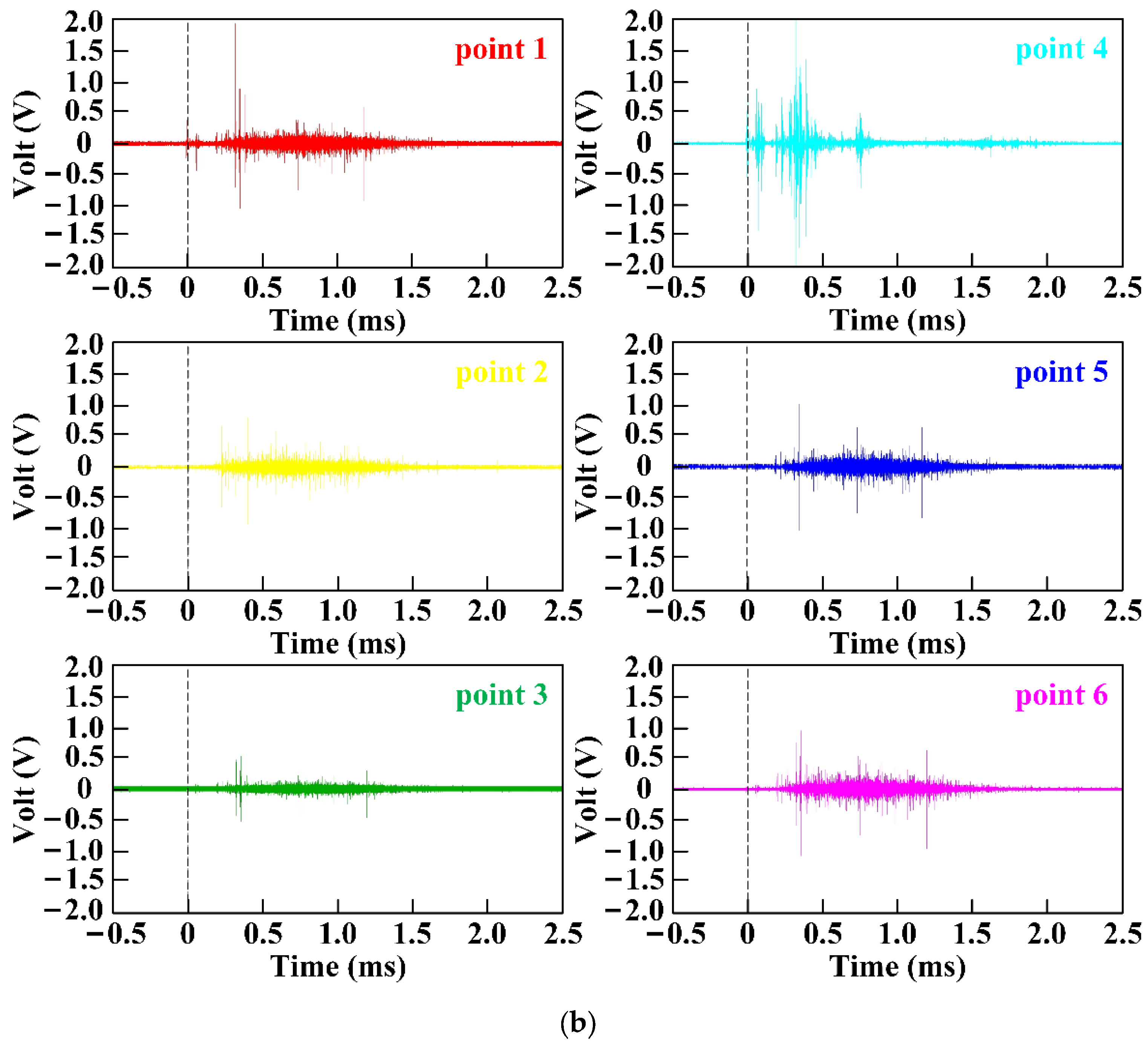
Due to the large mass of energetic materials, the electromagnetic radiation signal lasted for a long time, and an obvious phenomenon of electromagnetic wave reflection and superposition occurred after 50 ms. In order to facilitate a comparison with previous literature’s data and explore the law of electromagnetic radiation of explosion, this study extracted the electromagnetic signal within the initial period and combined the experimental results of small, equivalent energetic materials to summarize and study the law. The electromagnetic radiation signal of TNT is shown in Figure 5, and the electromagnetic radiation signal of 30 kg TNT is shown in Figure 5a, the electromagnetic radiation signal of 60 kg TNT is shown in Figure 5b. The electromagnetic signal generated by 60 kg TNT was significantly longer in duration than that generated by 30 kg TNT. The time-domain distribution of the 60 kg TNT electromagnetic pulse is denser, which proves that the explosive mass has an important influence on the duration of the electromagnetic radiation generated by the explosion. The greater the mass, the longer the duration of the electromagnetic signal.
The spectral distribution of electromagnetic radiation was an important parameter in the electromagnetic signal analysis, and the electromagnetic radiation signal was processed using Fourier transform with a Hanning window. The electromagnetic radiation spectrum of TNT explosion is shown in Figure 6. The frequency distribution of electromagnetic radiation of 30 kg TNT is shown in Figure 6a, and the frequency distribution of electromagnetic radiation of 60 kg TNT is shown in Figure 6b. The frequency of the electromagnetic radiation signal generated by the 30 kg TNT explosion is mainly concentrated in the low frequency band of 0~20 MHz and around 100 MHz. The frequency of the electromagnetic radiation signal generated by the explosion of 60 kg TNT is mainly concentrated in 0–100 MHz. The greater the mass of the explosive, the greater the frequency distribution of the electromagnetic radiation signal generated by the explosion, and the more concentrated the energy. The spectrum distribution of different test points is quite different, and the spectrum distribution of test points closer to the explosion center is more obvious, and they are distributed in the range of 0~100 MHz. The spectral distribution of the test points far from the explosion center is weak, and the electromagnetic radiation spectrum is mainly concentrated within 50 MHz. The electromagnetic radiation generated by the explosion of the same mass of explosives, the closer the distance to the detonation center, the larger the frequency distribution range of the electromagnetic signal. In addition, there are obvious differences in the electromagnetic frequency distribution in different directions, indicating that the electromagnetic radiation spreads unevenly.
According to the experimental data in the references, we concluded that the larger the mass of the energetic material, the larger the frequency distribution range of the electromagnetic radiation signal generated by the explosion, and the more concentrated the energy. The composition of energetic materials had the greatest influence on the spectrum distribution, and the electromagnetic radiation spectrum distribution produced by the explosion of energetic materials with different compositions had obvious specificity. This conclusion could be applied to the identification of explosive composition, and the electromagnetic frequency distribution in different directions would be different [23,24,25].
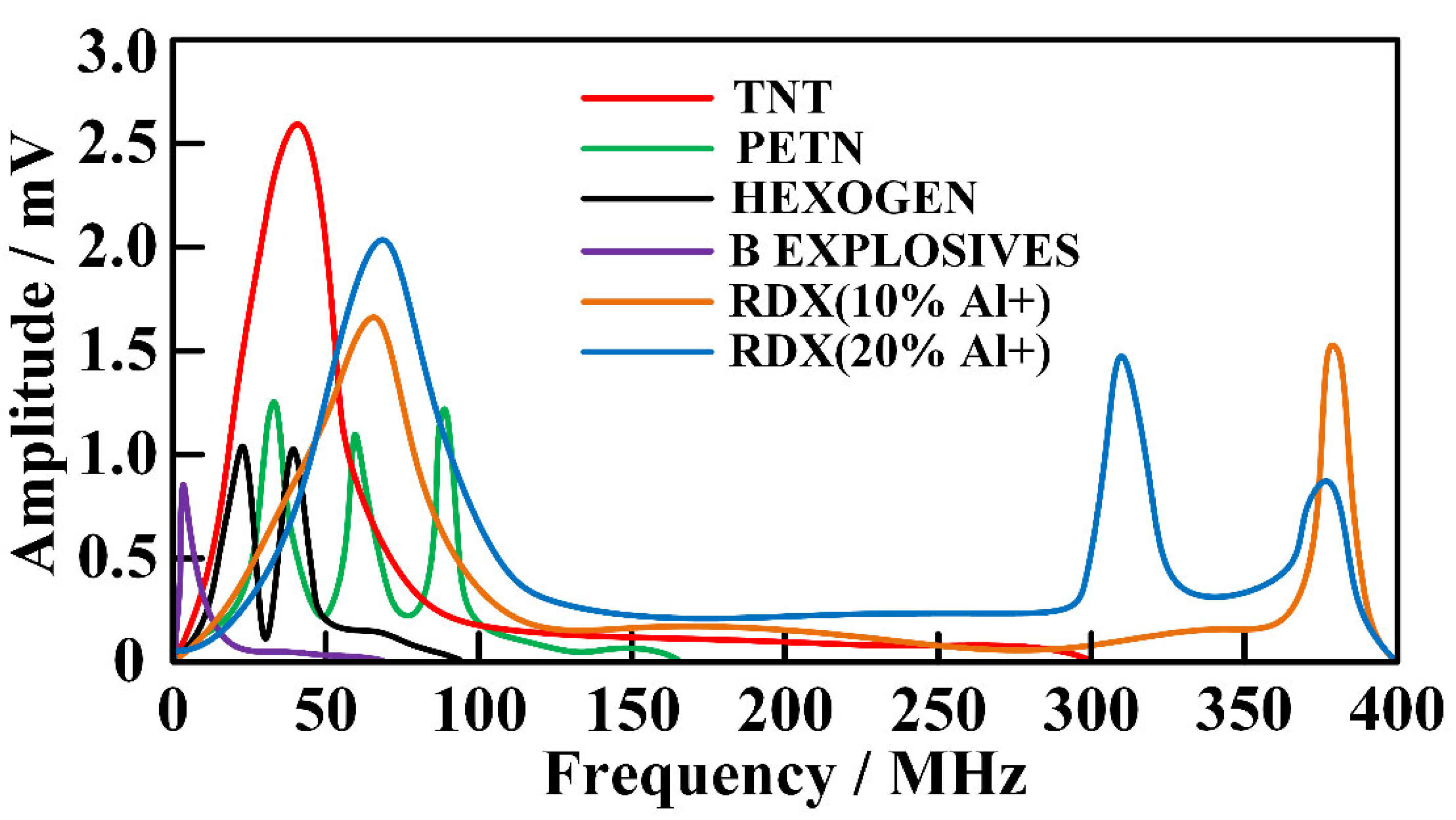
Figure 7 shows the electromagnetic spectrum distribution diagram of each component explosive. The electromagnetic radiation spectrum produced by PETN explosion is distributed around 30 MHz, 60 MHz, and 80 MHz. The electromagnetic radiation spectrum generated by the explosion of poly black explosives (RDX 96.5%, fluorine rubber 3%, graphite 0.5%) has obvious distribution around 20 MHz and 40 MHz. The spectrum of electromagnetic radiation produced by the explosion of B Explosives is distributed in the range of 0–50 kHz. The electromagnetic radiation spectrum generated by the explosion of RDX-based explosive (aluminum 10%) has obvious distribution around 380 MHz, and the electromagnetic radiation generated by the explosion of RDX-based explosive (aluminum 20%) has obvious distribution around 310 MHz and 380 MHz. According to the experimental data of TNT explosion, it can be concluded that the composition of explosives has the greatest influence on the spectral distribution, and the spectral distribution of electromagnetic radiation generated by the explosion of explosives with different compositions has obvious specificity. This conclusion can be applied to the identification and identification of the composition of explosives.

3.3. Analysis of the Energy-Domain Characteristics of Electromagnetic Radiation

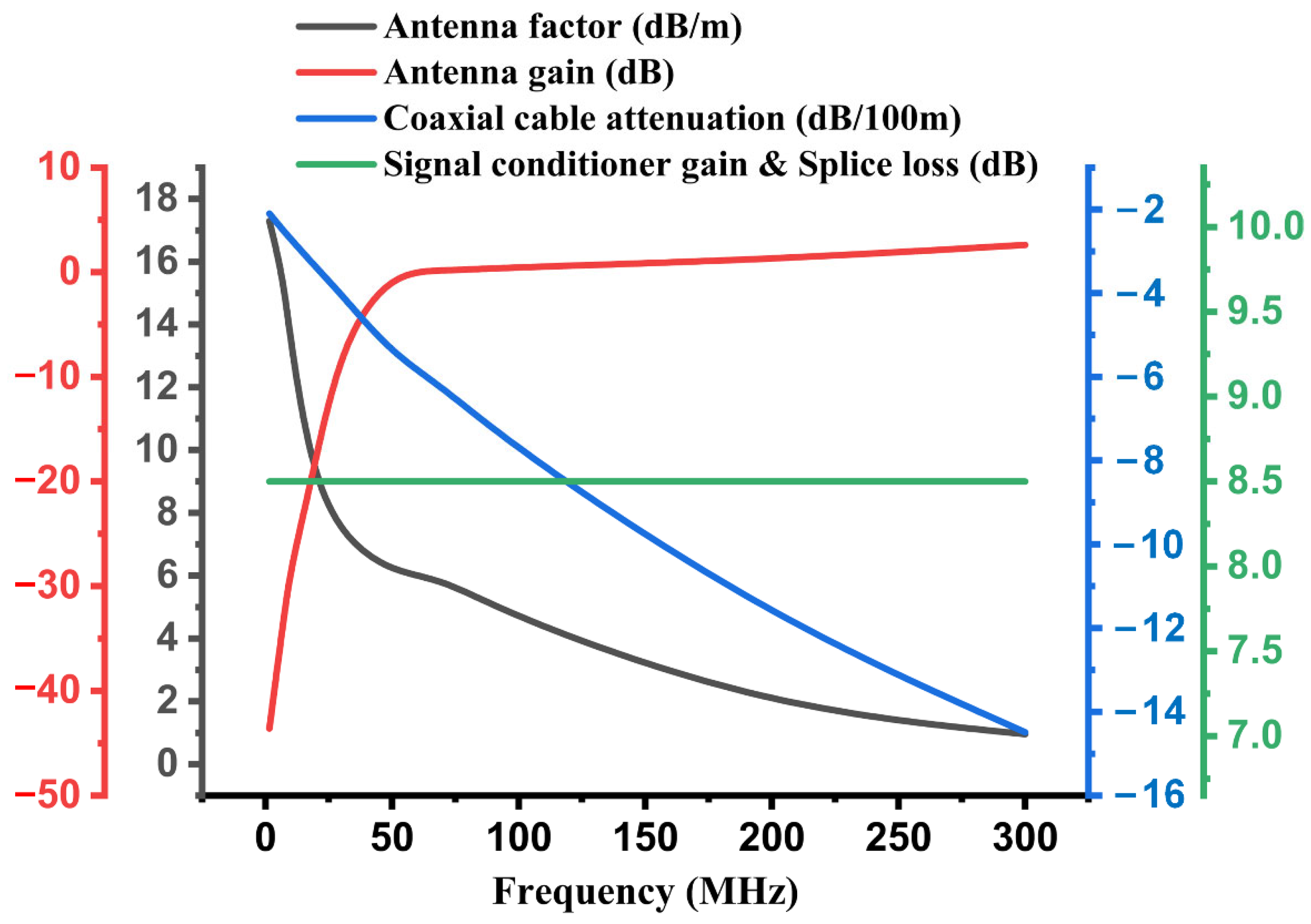
Electromagnetic radio frequency radiation hazards included protection location, spectrum characteristics, power intensity, signal time domain characteristics, and protection requirements. The environmental analysis of transient electromagnetic hazards included protection location, frequency band, and intensity. Electromagnetic strength was the most important reference value for electromagnetic hazard protection [26]. The energetic materials used in this experiment were of relatively high quantity, and the energy produced by the explosion was relatively strong. The data acquisition equipment was placed in a shelter for protection, and the distance between the data acquisition equipment and the front-end sensor (antenna) was relatively long. In the experiment, the SYV50-5-1 coaxial cable was used for the incoming signal transmission. The total length of the coaxial cable was 100 m. As the signal frequency increased, the attenuation rate of the electromagnetic signal would gradually increase. Therefore, it was necessary to perform attenuation compensation and gain correction in the experimental data processing, and we also considered factors such as antenna coefficient, antenna gain, signal conditioner gain, and adapter loss. The correction parameters of this experimental device are shown in Figure 8.
The output of the electromagnetic sensor (antenna) of the electromagnetic measurement system was the voltage value, and the voltage value could be converted into the electric field intensity E (V/m) by using the antenna coefficient and the equivalent power value. The output voltage of the measuring antenna was U (V), the antenna gain after calibration was G (dB), and the antenna coefficient was AF (dB/m). The space energy flux density is shown in Equation (5), the effective area of the antenna is shown in Equation (6), and the antenna received power is shown in Equation (7).
S = ( 1 2 E 2 ) / 120 π
A = G λ 2 / 4 π
P = S · A = U 2 / 2 Z 0
In the formulas, Z0 is the system impedance (Z0 = 50 Ω), and the propagation speed of electromagnetic wave in vacuum is the speed of light (c = 3.0 × 10⁸ m/s). The relationship between electromagnetic frequency f (Hz) and wavelength λ (m) is f λ = c . According to these formulas, Equation (8) was obtained, where the unit of fM is MHz. The antenna factor AF is in Equation (9). Substituting AF (dB) into Equation (9) yielded Equation (10). Finally, the conversion relationship between signal power P (dBm) and electromagnetic strength E (dBμV/m) was obtained as Equation (11).
u = 96.82 π E G 1 f M
AF = E U = π f M 96.82 G
AF = 20 log f M 10 l o g G 29.78
P = E AF 107
The experimental results after data correction are shown in Table 1. The maximum value of electromagnetic radiation intensity produced by 30 kg TNT explosion was 85.56 V/m, and the maximum value of electromagnetic radiation intensity produced by 60 kg TNT explosion was 168.86 V/m. The electromagnetic radiation intensity of 60 kg TNT measured at the same test point was 96.2–304.3% higher than that of 30 kg TNT. The electromagnetic radiation intensity produced by the explosion of explosives with different masses differed more than one time. For the electromagnetic radiation intensity produced by the explosion of explosives of the same quantity, the electromagnetic intensity decreased with the increase in the distance from the detonation center. For test points at the same distance and in different directions, there were also differences in the measured electromagnetic radiation intensity. The electromagnetic radiation intensity measured at the test points of 30 kg TNT in different directions was quite different, and the difference range was 17.35–102.17%. The electromagnetic radiation intensity measured by 60 kg TNT in different directions had a small difference, and the difference range was 11.1–17.7%.

4. Conclusions

To examine the phenomenon of electromagnetic radiation generated by the explosion of energetic materials, this study measured electromagnetic radiation during the explosions of energetic materials. According to the analysis of measured data in our investigation and similar data in relevant literature, the conclusions are as following:
(1)
The time-domain characteristics of the electromagnetic radiation generated by the explosion of energetic materials were most affected by the quantity of the explosive used. For energetic materials of the same mass, the time-domain distribution of electromagnetic radiation measured at different test points was roughly the same, but the farther away it was from the explosion center, the shorter the duration of electromagnetic radiation was. Additionally, there were some differences in the time-domain distribution of electromagnetic radiation measured at test points in different directions.
(2)
The frequency of electromagnetic radiation signals generated by the explosion of energetic materials was concentrated below 100 MHz. The greater the quantity of energetic materials was, the wider the frequency distribution of electromagnetic radiation was and the more concentrated the energy was. The composition of energetic materials had a significant influence on the spectrum distribution. The electromagnetic radiation spectrum distribution produced by the explosion of energetic materials with different compositions had obvious specificity, which could be applied to the identification of explosive components.
(3)
The electromagnetic radiation generated by the explosion of energetic materials can last for 600 ms after the explosion; the electromagnetic pulse was concentrated in the range of 0~300 ms, and the energy was most concentrated in the period of 80~110 ms. During the explosion of energetic materials with different masses, the first electromagnetic radiation signals appeared at different times, but they were all concentrated within 100 μs.
(4)
For the electromagnetic radiation intensity produced by the explosion of energetic materials of the same mass, the intensity decreased greatly with the increase in distance. There was a large difference in the intensity of electromagnetic radiation at the same distance but in different directions. The configuration of the charge and the method of detonation shifted the geometric movement pattern of the explosive change during the explosion process, resulting in the non-uniformity in the propagation of electromagnetic radiation.

Author Contributions

Conceptualization, Y.C.; methodology, Y.C.; formal analysis, Y.C. and S.G.; investigation, Y.C. and S.G.; data curation, Y.C. and S.G.; resources, D.K. and J.J.; writing—original draft preparation, Y.C.; writing—review and editing D.K. and S.G.; supervision, D.K. and J.J.; project administration, D.K. and J.J.; funding acquisition, D.K. and J.J. All authors have read and agreed to the published version of the manuscript.

Funding

This research was funded by Basic Technology Research Project for National Defense Science and Industry Administration (14021006010401).

Institutional Review Board Statement

Not applicable.

Informed Consent Statement

Not applicable.

Data Availability Statement

Not applicable.

Conflicts of Interest

The authors declare no conflict interest.

References

  1. Cui, Y.; Kong, D. Analysis of electromagnetic radiation spectrum during the explosion of energetic materials. IOP Conf. Ser. Earth Environ. Sci. 2020, 585, 012026. [Google Scholar]
  2. Kolsky, H. Electromagnetic Waves emitted on Detonation of Explosives. Nature 1954, 173, 77. [Google Scholar] [CrossRef]
  3. Boronin, A.P.; Vel’Min, V.A.; Medvedev, Y.A.; Stepanov, B.M. Experimental study of the electromagnetic field in the near zone of explosions produced by solid explosives. J. Appl. Mech. Tech. Phys. 1972, 9, 712–717. [Google Scholar] [CrossRef]
  4. Boronin, A.P.; Kapinos, V.N.; Krenev, S.A.; Mineev, V.N. Physical mechanism of electromagnetic field generation during the explosion of condensed explosive charges. Survey of literature. Combust. Explos. Shock Waves 1991, 26, 597–602. [Google Scholar] [CrossRef]
  5. Kuhl, A.L.; Bell, J.B.; Beckner, V.E. Heterogeneous Continuum Model of Aluminum Particle Combustion in Explosions. Combust. Explos. Shock Waves 2010, 46, 433–448. [Google Scholar] [CrossRef]
  6. Kuhl, A.L.; Bell, J.B.; Beckner, V.E.; Balakrishnan, K.; Aspden, A.J. Spherical combustion clouds in explosions. Shock Waves 2012, 23, 233–249. [Google Scholar] [CrossRef] [Green Version]
  7. Kuhl, A.; White, D.; Kirkendall, B. Electromagnetic waves from TNT explosions. J. Electromagn. Anal. Appl. 2014, 6, 280–295. [Google Scholar] [CrossRef] [Green Version]
  8. Li, J.; Song, W.; Ning, J. Theoretical and numerical predictions of hypervelocity impact-generated plasma. Phys. Plasmas 2014, 21, 082112. [Google Scholar] [CrossRef]
  9. Li, J.; Hao, L.; Li, J. Theoretical modeling and numerical simulations of plasmas generated by shock waves. Sci. China Technol. Sci. 2019, 62, 2204–2212. [Google Scholar] [CrossRef]
  10. Ren, H.; Chu, Z.; Li, J. Study on Electromagnetic Radiation Generated During Detonation. Propellants Explos. Pyrotech. 2019, 44, 1541–1553. [Google Scholar] [CrossRef]
  11. Chen, H.; Pan, X.; He, Y.; Jiao, J.; Shen, J.; Ben, C. Measurement of time-varying electron density of the plasma generated from a small-size cylindrical RDX explosion by Rayleigh microwave scattering. Plasma Sci. Technol. 2021, 23, 045401. [Google Scholar] [CrossRef]
  12. Van Lint, V.A.J. Electromagnetic Emission from Chemical Explosions. IEEE Trans. Nucl. Sci. 1982, 29, 1843–1849. [Google Scholar] [CrossRef]
  13. Soloviev, S.P.; Sweeney, J.J. Generation of electric and magnetic field during detonation of high explosive charges in boreholes. J. Geophys. Res. Earth Surf. 2005, 110. [Google Scholar] [CrossRef]
  14. Dai, Q.; He, J.; Wang, S.; Li, C. Experimental study on wideband electromagnetic radiation from plasma cloud. High Power Laser Part Beams 2010, 22, 1399–1403. [Google Scholar]
  15. Cao, J.; Xie, S.; Su, D.; Ma, Z. The experimental research on the electromagnetic radiation aroused by the detonation of explosive in the close space. J. B. Univ. Aeronaut Astronaut. 2011, 37, 1384–1387. [Google Scholar]
  16. Wang, C.; Zhou, G.; Cai, Z.; Tang, Y.; Zhao, S.; Li, X.; Lin, Y.; Chu, Z. Measurement and analysis of shock wave overpressure of thermal explosion of charge with shell. Acta Armamentarii 2012, 33, 574–578. [Google Scholar]
  17. Cui, Y.; Shang, F.; Kong, D.; Wang, L. Research on testing technology of electromagnetic radiation characteristics in explosive field. Initiat. Pyrotech. 2019, 5, 1–5. [Google Scholar]
  18. Cui, Y.; Jiang, J.; Kong, D.; Gao, S.; Wang, S. Study on Electromagnetic Radiation Interference Caused by Rocket Fuel. Sensors 2021, 21, 8123. [Google Scholar] [CrossRef]
  19. Gao, S.; Tian, G.Y.; Dai, X.; Zhang, Q.; Wang, Z.; Yang, X.; Wang, Q.; Jia, N. A Lightweight Wireless Overpressure Node based Efficient Monitoring for Shock Waves. IEEE/ASME Trans. Mechatron. 2020, 26, 448–457. [Google Scholar] [CrossRef]
  20. Gao, S.; Lin, Y.J.; Zhu, J.J. The Effect of Mounting Structure and Piezoelectric Pressure Probe Sensor Incident Angle on the Free-Field Measurement. IEEE Sens. J. 2019, 19, 7226–7233. [Google Scholar] [CrossRef]
  21. Gao, S.; Tian, G.Y.; Dai, X.; Fan, M.; Shi, X.; Zhu, J.; Li, K. A Novel Distributed Linear-Spatial-Array Sensing System Based on Multichannel LPWAN for Large-Scale Blast Wave Monitoring. IEEE Internet Things J. 2019, 6, 9679–9688. [Google Scholar] [CrossRef]
  22. Cui, Y.; Kong, D. Analysis of electromagnetic radiation spectrum of a certain type of bomb during static explosion. Initiat. Pyrotech. 2020, 5, 18–22. [Google Scholar]
  23. Tasker, D.G.; Whitley, V.H.; Lee, R.J.; Elert, M.; Furnish, M.D.; Anderson, W.W.; Proud, W.G.; Butler, W.T. Electromagnetic Field Effects in Explosives. AIP Conf. Proc. 2009, 1195, 335. [Google Scholar] [CrossRef]
  24. Wang, C.; Liu, X.; Li, X.; Zhao, S.; Wu, Y. The experimental research on the electromagnetic radiation aroused by detonation of explosive. Acta Armamentarii 2014, 35, 188–192. [Google Scholar]
  25. Tang, E.L.; Tang, W.F.; Xiang, S.H.; Li, L.X.; Zhang, W.; Yu, H.; Zhao, X.Y. Coil measurement system for weak magnetic field generated by hypervelocity impact. High Power Laser Part Beams 2010, 22, 1132–1136. [Google Scholar] [CrossRef]
  26. Cui, Y.; Kong, D.; Zhang, X.; Wang, L. Measurement and analysis of electromagnetic radiation signals of TNT explosion. Chin. J. Energet. Mater. 2021, 29, 241–250. [Google Scholar]
Figure 1. (a) electromagnetic radiation experimental device; (b) test points distribution; (c) experiment field.
Magnetochemistry 08 00057 g001
Figure 2. Explosion experiment process of energetic material.
Magnetochemistry 08 00057 g002
Figure 3. Electromagnetic radiation signal of TNT explosion. (a) Full-time electromagnetic radiation signal of 60 kg TNT explosion; (b) time-domain distribution of electromagnetic radiation of 60 kg TNT explosion; (c) full-time electromagnetic radiation signal of 30 kg TNT explosion; (d) time-domain distribution of electromagnetic radiation of 30 kg TNT explosion.
Magnetochemistry 08 00057 g003
Figure 4. Delay response time of electromagnetic radiation signal of TNT explosion. (a) The delay time of electromagnetic signal in test point 1 of 30 kg TNT explosion; (b) the delay time of electromagnetic signal in test point 4 of 30 kg TNT explosion; (c) the delay time of electromagnetic signal in test point 1 of 60 kg TNT explosion; (d) the delay time of electromagnetic signal in test point 4 of 60 kg TNT explosion.
Magnetochemistry 08 00057 g004
Figure 5. Electromagnetic radiation of TNT explosion. (a) Electromagnetic radiation of 30 kg TNT; (b) electromagnetic radiation of 60 kg TNT.
Magnetochemistry 08 00057 g005aMagnetochemistry 08 00057 g005b
Figure 6. Electromagnetic radiation spectrum of TNT explosion. (a) Frequency distribution of electromagnetic radiation of 30 kg TNT; (b) frequency distribution of electromagnetic radiation of 60 kg TNT.
Magnetochemistry 08 00057 g006
Figure 7. Electromagnetic radiation spectrum of different explosives.
Magnetochemistry 08 00057 g007
Figure 8. Experimental data correction parameters.
Magnetochemistry 08 00057 g008
Table 1. Experimental data of electromagnetic radiation of TNT explosion.
Test PointPeak Voltage/VEffective Voltage/VSignal Power/dBmElectromagnetic Intensity/V∙m−1
30 kg60 kg30 kg60 kg30 kg60 kg30 kg60 kg
Point 11.4261.91411.40820.46834.15439.23185.56168.86
Point 20.6441.5637.18715.84130.14137.00557.49130.68
Point 30.7030.8982.3719.18120.50832.26818.7375.74
Point 40.5072.5005.16118.88127.26438.53042.32151.99
Point 50.6831.8753.82914.16824.67236.03629.29114.05
Point 60.3320.5852.1524.21419.66725.50415.9664.33
Publisher’s Note: MDPI stays neutral with regard to jurisdictional claims in published maps and institutional affiliations.