Article

Modeling of the Particle Build-Up Evolution on a Single-Wire Magnetic Capture from Axial Stream Flow

1
Department of Biomedical Engineering, Inonu University, Malatya 44280, Turkey
2
Department of Electrical and Electronics Engineering, Inonu University, Malatya 44280, Turkey
*
Author to whom correspondence should be addressed.
Magnetochemistry 2022, 8(2), 15; https://doi.org/10.3390/magnetochemistry8020015
Submission received: 31 October 2021 / Revised: 18 January 2022 / Accepted: 19 January 2022 / Published: 24 January 2022

Abstract

:
The kinetic equation of the accumulation of magnetic particles from axial flow on a magnetized ferromagnetic wire in an external homogeneous magnetic field has been developed in this study. A new differential equation of the evolution of the accumulation radius over time, which considers both the capture and the detachment of the particles in the accumulation profile on the wire, has been formulated. The evolution of the radius of the accumulation profile over time was obtained from both the differential kinetic equation based on population theory and from the stochastic Fokker–Planck equation. In the limit approach ( t ), it was observed that the expressions of the saturation radius of the accumulation radius on the magnetized wire of the particles obtained from both models were the same. It is emphasized that the obtained results are valid for both the initial and steady-state build-up of the particle capture process. These results were compared with the experimental results from the literature, and it was observed that the theoretical and experimental results were in good agreement. The effects of both capture and detachment events on the accumulation of particles on the magnetized wire were evaluated.

1. Introduction

Despite a half-century of progress, improvements on the high-gradient magnetic separators (HGMSs) still continue and they are successfully applied in new industrial areas [1,2,3,4,5,6,7,8,9,10,11,12,13,14,15]. This physical method is based on the principle of depositing the submicron-sized particles of liquids and gases by capturing them in a high-gradient magnetic field. This separation method does not change the chemical properties of the working media and exhibits a remarkably high separation performance. HGMS structures that are made of ferromagnetic matrix elements (wire, rod, sphere, etc.) which are placed in an external homogeneous magnetic field have the most convenient features in terms of energy saving as well as simplicity. When media carrying submicron-sized magnetic particles pass through the HGMS matrix, these particles can be easily captured and deposited in a high-gradient magnetic field. HGMSs, which were initially developed to be used in the enrichment processes of minerals [1,2,3,4,5,6,7,8,9,10,11,12,13,14,15], were rapidly and effectively adapted in all fields, including environment, heavy industry, chemistry, food industry, and especially in medicine and biology [16,17,18,19,20,21,22,23,24,25]. With the new application areas, the theory and practice of HGMSs has significantly advanced [26] in the matrices used in HGMS systems and especially the ones composed of ferromagnetic wires [1,4,6,10]. In such matrices, although the external homogeneous magnetic field is perpendicular to the ferromagnetic wire, the direction of suspension flow carrying the magnetic particles is in the transversal, longitudinal, or axial direction compared to this wire. Axial magnetic separators are the most convenient type of HGMS, both economically and structurally. Therefore, the most comprehensive HGMS theory has been developed for axial-type magnetic separators [27,28,29,30,31,32,33,34,35,36,37,38,39,40,41,42,43,44,45]. The basis of this theory is a system of differential equations expressing the mutual effects of magnetic ( F M ) and hydrodynamic ( F D ) forces acting on the magnetic particle moving in the gradient magnetic field, formed around the infinite ferromagnetic wire magnetized by an external homogeneous magnetic field. In HGMS theory, this model is defined as the “trajectory model” [1,4,6,29]. The most studied approach in the literature based on the “trajectory model” in axial-type HGMSs is the capture of magnetic particles on a single magnetized wire [27,28,29,30,31,32,46]. In some studies, magnetic particle capture problems in magnetized wires with ordered or random matrix elements have also been investigated [28,30,31,32,42,47,48,49,50]. In many studies, magnetic particle capture problems on a single magnetized wire have been investigated using different flow cell models in both potential and laminar flows of suspensions [27,28,29,47,49,51,52,53]. In some studies, the effect of the non-Newtonian flow properties of the suspension carrying magnetic particles on the capture of particles according to the “trajectory model” was also evaluated [47,52,54]. It has been emphasized that such approaches are important in vivo experiments in magnetic drug targeting processes in medicine and biological environments [55].
The problems of keeping magnetic particles in axial magnetic separation with a bounded flow field based on the “trajectory model” were also sufficiently studied in the literature for the first time [41,56]. In the literature, the capture of thin sized ( < 1 μ m ) magnetic particles using the “trajectory model” has also been investigated using diffusion equations [49,57,58,59,60]. By developing the “trajectory model”, the problems of build-up capturing magnetic particles on the magnetized wire in the axial potential flow of the suspension were investigated [30]. The kinetic equation of the particle capture phenomenon in parallel-type HGMSs was formed and analytical solutions were obtained [30,31,32]. The differential equation of the build-up of magnetic particles by capturing them in axial flow-type HGMSs has also been established [32,33,34,35,36,37,38]. Thus, the theory that considers both the travelling and accumulation time of these particles on the magnetized wire has been developed [38]. In many studies, theoretical and experimental investigations of the capture of magnetic particles on the magnetized wires or rods with different geometries (ellipse, square, rectangle, etc.) have been carried out [39,42,43,61].
In addition to the theoretical studies, experimental investigations of the capture of magnetic particles in axial flow on the magnetized wire have also been carried out in the literature [30,31,32,34,35,36,37,62,63]. In these experiments, videos and photographs of both capture of the particles and formation of the build-up or accumulation profile on the wire were obtained. Based on these results, an empirical model of the evolution of the initial build-up profile over time was established [30,31,32,38]. Analysis of these studies indicates that some unsolved problems exist in magnetic particles captured and built-up on a magnetized wire in the theoretical and practical investigation.
In general, the analytical solution of the particle motion equation around the magnetized wire in a non-steady-state case is not possible. Therefore, an approximation solution of this equation can be obtained. In this case, two theoretical approaches are used to investigate the phenomenon of particle capture and accumulation processes:
(1)
Determination of the effective length that this particle can capture on the magnetized wire, based on the motion equation of the particle around the wire.
(2)
Establishment and solution of the kinetic equation of the build-up profile, which determines the evolution of the particles captured and accumulated on the wire.
In HGMS theory, the first approach is frequently used. However, for determining the performance, the effective working time, other output parameters, and for realizing optimum design and control of HGMSs, it is more important to examine the kinetic equation of the build-up profile. According to the analysis of the results presented in the literature, it showed that examination of this approach in HGMS theory and practice is insufficient [32,38]. One of the most important reasons for this insufficiency is that the kinetic equation of the build-up profile is quite approximate. Therefore, it does not fully explain the physical properties of the particle capture–detachment mechanism on the wire. Thus, the kinetic equations presented in the literature describe the evolution of the particles deposited on the magnetized wire only at the initial moment [32,34,35,38]. In this case, it is impossible to obtain the evolution of the accumulation radius of the build-up profile at t . This is because, in the approach, it is assumed that the particles accumulate by capturing on the wire from the initial moment, and that they do not break off and maintain their position until the end. In reality, the particles accumulated on the wire may break off under suitable conditions and be caught again on the wire or pass without being caught at all. In other words, the detachment process of captured particles is ignored in these approaches. Moreover, this event may be repeated once or several times. This phenomenon, which is dependent on the influence of the geometric, magnetic, hydrodynamic, rheological, and other parameters of the HGMS system, should be considered in the kinetic equation. Hence, it should also be considered that both the capture and detachment of particles are random stochastic events in the kinetic equation of the build-up profile. In this case, the build-up profile obtained from both the “trajectory model” and the stochastic model should be evaluated by comparing the saturation radius.
In this article, the kinetic equation of the deposition of magnetic particles by keeping them in axial flow is obtained by considering both the capture and detachment of the particles. From the analytical solution of this equation, the radius of the build-up profile of the particles on the wire and the evolution of the build-up saturation radius, which is the limit value of this radius, are obtained. The saturation radius of the build-up profile is modeled by using two methods. The first one is used to determine the evolution of the build-up radius of the particles on the wire over time based on the population theory. The second one is used to obtain the stochastic variation function of the evolution of the deposition radius along the wire as a special solution of the Fokker–Planck equation.

2. Formulation of the Problem

In general, the principal schema of capturing and accumulating magnetic particles on a magnetized ferromagnetic wire in an external magnetic field in axial HGMSs is illustrated in Figure 1.
The ferromagnetic wire with radius, a , length, L   ( L > > a ), and saturation magnetization value, M s , lies on the O z axis, and the external homogeneous magnetic field, H 0 , acts orthogonal to this wire in the O x direction. The magnetic particle in spherical form with radius, b , magnetic susceptibility, k p , and density, ρ p , contained in the carrier suspension medium with density, ρ , and magnetic susceptibility, k f , makes potential flow in the O z direction in parallel with the ferromagnetic wire with v 0 velocity. The external magnetic field, H 0 , allows the ferromagnetic wire to be sufficiently magnetized. Thus, magnetic particles are captured and accumulated on this wire with accumulation profile radius R .
The carrier medium is an ideal suspension when compared to the magnetized ferromagnetic wire and is a viscous suspension according to the particles it contains. The movement of particles around the magnetized wire and their accumulation on this wire by capturing are generally studied according to the “trajectory model” [1,4,30,41]. Based on this approach, the motion equation is studied as a differential equation formed from the balance of all forces acting on the particle. As in these studies, particle sizes are traditionally assumed to be less than 1–2 µ m [1,2,3,4,5,6]. In this case, it is assumed that the main forces acting on the particle are magnetic ( F M ) and hydrodynamic ( F D ) forces, and the effects of other forces can be ignored. Under these conditions, the motion equation of the particle in the magnetic field can be simplified as follows:
F M + F D = 0
If we consider the obvious expressions of these forces, the accumulation of particles in the magnetic field according to the “trajectory model” in HGMS theory can be examined with two approaches:
i.
Determining the HGMS performance by defining the area of the particle’s capture region (active region) or the capture radius on the magnetized ferromagnetic wire.
ii.
Determining the capture saturation radius and HGMS performance from the initial accumulation profile of the particles deposited on the magnetized wire.
The differential equation of capturing the particle in axial parallel potential flow in a high-gradient magnetic field is obtained as follows [1,4,29,30,31]:
d r a d t = v m a   ( K μ r a 5 + cos 2 r a 3 ) r a d d t = v m a   sin 2 r a 3 d z a d t = v 0 a
where v m = 2 μ 0 k H 0 M s b 2 9 η a is the “magnetic velocity” [1], ( r , , z ) are cylindrical coordinates, r a = r a , z a = z a , η is dynamic viscosity of the carrying fluid, M s is saturation magnetization of the ferromagnetic wire, k = k p k f is effective magnetic susceptibility, and K μ is the coefficient of magnetization, K μ = { M s 2 H 0 1   f o r f o r   H 0 M s 2 H 0 < M s 2 .
Analytical and numerical solutions of this equation system for laminar and potential flows of both Newtonian and non-Newtonian suspensions have been sufficiently studied in the literature [4,28,30,42,47,52,63,64,65,66,67]. Simple formulas for HGMS performance can be determined by using the “capture cross-section” [27,29,30,31] or “capture radius of the wire” [1] parameters obtained from the solution of Equation (2).
To determine the HGMS performance or other integral characteristics, the build-up profile of the particles captured on the magnetized wire is required. Examination of the profile is obtained from the improved solution of Equation (2). This method determines not only the output characteristics of the HGMS, but also the kinetics of the particle capture mechanism in the matrix of the magnetic separator. These results allow determination of the evolution of the performance of HGMSs over time in advance and obtaining the optimum design and control of the magnetic separator for circulating operation. As shown in Figure 1a, let us assume that the magnetic particles entering the active region of the magnetized wire with the Δ S 0 field from the initial point ( r 0 , 0 , 0 ) are deposited by capturing at the Δ S z surface area at the ( R , Φ , Z ) point on the wire. The build-up of these magnetic particles in this region is expressed by the following differential equation system [30,31,32]:
d R a d t = cos 2 Φ τ R a 3 d Φ d t = sin 2 Φ τ R a 4 d Z d t = 1 τ with   τ = ϵ ρ p a c 0 v m ,   Z = ( Z a   v m v 0 ) ,   R a = R a
where ϵ is the packing volume fraction of solids in the deposit, c 0 is the mass density and concentration of the solid fraction in the fluid suspension, and ϵ ρ p is the effective density of the magnetic particles in the deposit on magnetized wire. The solution of the build-up differential equations of particles, expressed by Equation (3), allows determining the initial build-up profile of the accumulation and its profile at different times [30,31,32]. The resulting expressions obtained in the more accurate solution of Equation (3) provided the change of saturation accumulation radius, R s , according to the Reynolds number of the particle and the v m / v 0 ratio in the accumulation event [38].
In the literature, the equation in which the evolution of the accumulation radius over time is consistent with the experimental data is provided as follows [35,36]:
R a n = A t + 1
here, A and n are empirical values depending on the magnetic, geometric, and hydrodynamic parameters of the system, and these are essentially variable parameters. For example, if the Reynolds number of the particle changes in R e < 0.3 and R e > 10 3 , n   continuously changes from n = 4 to n = 2.5 [34,36]. This range of variation may differ if the morphology and concentration of the magnetic properties of the captured and accumulated particles change. While n = 3 remains constant in the accumulation of strongly magnetic particles ( F e 3 O 4 ) [46], n may vary in the range of ( n = 2.9 4.2 ) or remain as n = 3 in weak magnetic particles, depending on the suspension concentration [36]. Although Equation (4) changes slightly with the increase in the viscosity of the medium carrying the magnetic particles, n = 3 remains.
However, all these solutions represent the initial moment of the accumulation and aggregation process. In experimental and theoretical studies, the accumulation profiles of the particles on the magnetized wire may be different depending on the magnetic field and geometry of the HGMS system, magnetic properties, morphology of the captured particles, and the flow hydrodynamics (e.g., potential, laminar, and turbulence) of the suspension [68]. In addition, the accumulation saturation profile is dependent on the Reynolds number. For example, the principle profiles of the accumulation saturation radius at high and low Reynolds numbers are shown in Figure 1b,c [68]. Unlike the aforementioned studies [31,32,38], which are based on the balance equation of the forces acting on the particle in the capture region, the accumulation saturation radius in [68] is determined according to the balance equation of the moments acting on the particle positioned on the saturation surface. However, this statement does not express the kinetics of the accumulation process over the whole study period because the accumulation of captured particles is assumed to be only a continuously developing event in these studies. In addition, according to the studies presented in [69], high performance can be obtained even in advanced turbulent flows in parallel flow HGMSs. Therefore, the accumulation of particles on the magnetized wire is observed as stochastic capture and detachment events. In this respect, Equations (2) and (3) consider only capture in these events, and detachment processes of capturing particles are ignored. However, with the development of Equation (3), a theoretical model can be formulated that considers both the capture and detachment through the particles on the magnetized wire. In this model, the following assumptions are made by considering the results obtained from the theoretical and experimental studies presented in [36]:
(a)
The initial accumulation of particles captured on the magnetized wire occurs in regions of the highest magnetic field gradient ( 0 ). The accumulation of particles in these regions of the magnetized wire is predominantly aggregation during the initial phase of deposition processes. Deposition of the captured particles on the wire remains predominant until the saturation radius ( R s ) is formed. During this process, if the particle captured in the active region breaks for any reason (turbulence, drag, etc.), this particle can be drifting and captured in another position on the wire, or the breaking events of the captured particles are very weak.
(b)
Detachment and divergence events of the particles are more dominant at the level of the saturation profile of the particles formed on the magnetized wire and in the region above it ( R R s ). This is a critical point for HGMS performance, after which the performance becomes minimal or negligible. The time required for this condition to occur is also expressed as the safe operating time of the separator.
As seen from these approaches, the accumulation profile of particles on the magnetized wire can be evaluated by the variation of the accumulation radius ( R ). In general, this change is a stochastic event that occurs with both capture and detachment events, and the analysis of events can be obtained by solutions of stochastic integro-differential equations. However, the capture and breaking off of particles for a certain period can be considered as the change of the median statistical value of the accumulation radius. In this case, it can be simplified to examine these events with stochastic equations.
In fact, the effects of a critical Reynolds number and turbulence events on performance have not been studied in detail in HGMS theory and practice presented in the literature [1,2,3,4,5]. In all cases, the flow of the suspension carrying the magnetic particles is assumed to be potential or laminar, and it is assumed that the performance of the HGMS will decrease with the formation of a turbulent flow regime. However, due to the nonlinear variation of the velocity profile in the porous media, turbulent flow in the pores can occur without the formation of the critical Reynolds number. In this case, the initial or developing small-scale turbulences do not decrease the HGMS performance—it may even increase it to a certain limit. Accordingly, unlike the matrices of conventional separators, the effects of small-sized turbulence events on the performance of magnetized matrices should be examined more seriously. In this study, the accumulation kinetics of the particles on the magnetized wire is discussed only by considering the mechanism of capture–detachment events. In this study, the development of the build-up profile of the particles on the wire was studied with two approach models, as follows:
(a)
The solution model of the differential equation expressing both aggregation and breaking away of particles captured in the active region. This model is generally constructed from nonlinear integro-differential equations based on population balance [70].
(b)
The solution model with the Fokker–Planck equation as a stochastic event observed with both capture and detachment processes at the same time in turbulent flow of particles captured in the active region.
The differential equation, which also expresses the capture and detachment events at the saturation radius level ( R s ), can be formed as follows:
The continuous aggregation of particles captured on the magnetized wire in the magnetic field is determined by Equation (3) in the ( Φ 0 ) condition. Breaking of the captured particles develops with the effect of adhesion forces and small-scale turbulent oscillations, which occur due to the roughness caused by the accumulation of the captured particles on the wire. This breaking velocity achieves growth with the increase of the accumulation radius. In other words, it is usually d R d t   ~ R .
In this case, considering that ( Φ 0 ) based on Equation (3), the change of the accumulation radius after saturation time can be written considering both the capture and detachment events of the particles with the following equation:
d R a d t = K a R a 3 K d R a R a | t = 0 = R s a
here, K a = 1 / τ is the accumulation coefficient, K d is the detachment coefficient, R s a = R s / a , and R s is the particle build-up saturation radius. The detachment coefficient is usually directly proportional to the particle entrainment velocity, the flow rate of the suspension, and the size of the deposited particles and depends on the other hydrodynamic and physical parameters of the system. It can be evaluated experimentally or according to the kinetics of the particles deposited on the wire or the forces or moments acting on the particles in the last layer of the accumulation profile [26,38,68].
The solution of Equation (5) is obtained as follows:
R R s = K 1 ( 1 e t 1 ) + e t 1 4 ,   K 1 = K a K d R s a 4 = K R s a 4 ,   t 1 = 4 K d t
As seen from Equation (6), when t 1 , the accumulation radius of particles becomes:
R R s = K a K d R s a 4 4
On the other hand, the balance between capture and detachment in the accumulation event of particles is also obtained when d R d t = 0 . Based on Equation (5), this is achieved when R a = R s a = K a K d 4 = K 4   . In this case, since K = 1 , this value determines the limit of the build-up profile.
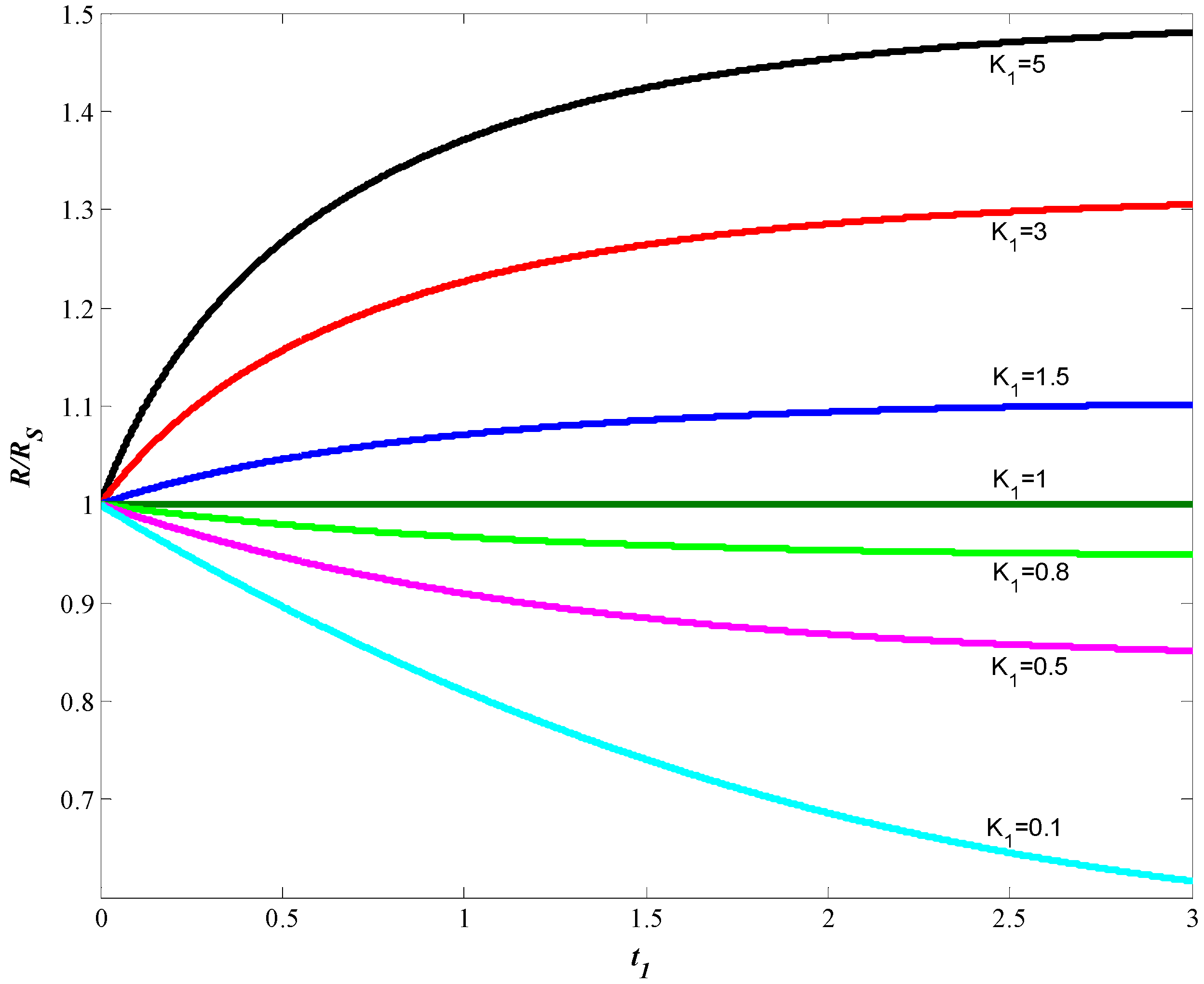
Figure 2 shows the non-dimensional changes of R R s = f ( t 1 ) at different K 1 values. When K 1 > 1 , the captured particles predominantly accumulated on the wire. Moreover, when K 1 > > 1 , the capture and accumulation probability of particles is more advanced. In Equation (5), in potential and laminar flow situations, the limits of these events can be approximately determined at a certain flow rate of the suspension. For example, in the first calculations, it is possible to assume that R s a   10 for the radius particles with δ < 10   μ m in axial flow [34,36]. In small-sized turbulent flow, even in K 1 1 states, the probability of coagulation and re-attachment of these particles by colliding in the active region is high due to the breaking of previously captured particles.
The saturation radius ( R s ) of the accumulation profile is assumed as the initial condition in Equation (5). Because, after the saturation radius was formed, the capturing and detachment processes of the particles were more intense. In this case, the full separation time can be large enough. However, this equation also enables determining the deposition evolution of particles on the wire from the initial moment R | t = 0 = a because the time required for the particles to be captured on the wire from the initial time they enter to the capturing zone (traveling time) is very small compared to the full separation time.
In these cases, the solutions of Equation (5) would be as follows:
R a = K ( 1 e t 1 ) + e t 1 4 t 1 = 4 K d t   ,   R | t = 0 = a
The capture and build-up of the magnetic particles in the active region of the wire can be modeled by using the Fokker–Planck equation as stochastic processes [71]. The Fokker–Planck stochastic equation is used to analyze disperse systems in which the media properties and dimensions of the disperse mixture are continuously changing [72,73]. In fact, the variation of the accumulation radius in the case of both capture and detachment of the particles is in the pulse or step form, and they are not continuous. However, since the radius of saturation is large enough compared to the dimensions of the particles, we can assume that this variation occurs with small amplitude fluctuation which is approximately constant. Therefore, we can use the Fokker–Planck equation to examine this phenomenon, assuming the variation of the saturation radius as approximately continuous when the particles are captured and build-up on the magnetized wire. We assume that the variation of the accumulation radius with time is according to Equation (5). To facilitate future applications, Equation (5) can be written based on the square of the saturation radius:
d y d t = 2 K a y 2 K d y
where y = R a 2 .
In this case, the simple form of the Fokker–Planck equation would be as follows [72,73]:
P ( y , t ) t = 2 K d y [ ( K y y ) P ( y , t ) ] + B a 4 2 P ( y , t ) y 2   P ( y , t ) | t = 0 = P 0 ( y )
here, P ( y , t ) is the density of the distribution function of the variation of the accumulation radius, and B   is the stochastic diffusion coefficient.
Some analytical solutions of the Fokker–Planck equation for steady states are presented in [72]. Analytical solutions for different types of kinetic equations have been studied in detail in [73]. In this respect, the analytical solution of Equation (10) can be obtained as [73]:
P ( y , t ) = y θ e x p ( a 4 K d y 2 B ) n = 0 C n L n ( α ) ( a 4 K d y 2 B ) e x p ( 4 K d n t )
here, θ = 2 a 4 K a B , α = θ 1 2   , L n ( α ) is the Laguerre polynomials, and the coefficient
C n = θ θ + 1 2 0 P 0 ( y ) L n ( α ) ( a 4 K d y 2 B ) d y   K θ + 1 2 2 θ 1 2 Γ ( n + θ + 1 2 ) n ! .  
Equation (11) allows examining the changes of the distribution function continuously with time considering both the capture and detachment events. In this case, since L n ( α ) ( a 4 K d y 2 B ) = 1 , the special solution of the distribution function in case t→∞ would be as follows [73]:
P ( y , t ) = P ( y ) = C 0 y θ e x p ( a 4 K d y 2 B ) ,   C 0 = 2 ( K d B ) θ + 1 2 B
An especially important result is obtained from Equation (13). If the magnetized wire is long enough (theoretically infinite), the distribution function of the accumulation radius on the wire reaches the limit value, P ( y , t ) = P ( y ) . Moreover, this value is independent of the initial distribution value ( P 0 ). Therefore, the limit value of the accumulation radius (saturation radius, R s ) can be calculated as follows:
y = R s a 2 = a y P ( y , t ) d y
Using Equation (13), we can determine the coordinates of the maximum value ( R or R s ) of the limit approximation which the accumulated particles spread along the wire:
P ( y , t ) y = 0   y m a x = K a K d
Therefore, the accumulation radius of captured particles in the t state is:
R s a = K a K d 4
As can be seen, this expression is the same as the result obtained in Equation (7). According to these results, as the K a / K d ratio decreases, in other words, as the accumulation of particles captured on the magnetized wire weakens, the maximum of the dispersion function shifts towards the lower values of the accumulation radius. On the contrary, if the K a / K d ratio increases, that is, the probability of capturing and accumulating particles is more effective, the maximum of the dispersion function shifts towards higher values of the accumulation radius. In other words, the accumulation saturation radius of the particles deposited on the magnetized wire will be large in the regions where the capture is dominant along the wire and less in the regions where the detachment is dominant. On the other hand, as can be seen from Equation (16), the accumulation saturation radius, R s , is determined by the K a / K d ratio. Therefore, the relationship between K a and K d can also be evaluated by using R s values from the experiments. As a result, these parameters express all the physical parameters (e.g., magnetic, geometric, rheological, and hydrodynamic) that affect the accumulation of particles. Accordingly, it may not always be possible to analytically pre-calculate K a and K d in all cases. However, the evaluation of these parameters can easily be performed for special cases. For example, in the case of the accumulation of magnetic particles captured on magnetized wire in parallel flow HGMSs, the K a parameter is specified in Equation (5). Hence, by determining the intermediate statistical value of the radius, R s , from experimental studies (e.g., [36]), the detachment coefficient of the particles under these conditions can be easily evaluated, K d = K a R s a 4 . For example, in practical applications, if it is assumed that R s = ( 10 12 ) a in axial flow HGMSs ( H = 400 600   kA / m ), it can be evaluated as K d   10 4   K a . It is clear that this relationship will also be different for the results of different experiments performed under different conditions.

3. Results and Discussion

The accumulation of submicron-sized magnetic particles on the magnetized wire in the axial potential flow is generally expressed by the empirical Equation (4) at the initial moment. However, with the change of the magnetic, geometric, and hydrodynamic properties of the system, the coefficients ( n and A ) included in this equation take values in a wide spectrum. At the same time, Equation (4) does not express the full evolution of capture of the particle over time. Differential Equation (3), which states the build-up event of the captured particles in the potential axial flow, expresses the accumulation of the particles, and neglects the phenomena of detachment and re-attachment of the captured particles in this process. However, the capture–detachment events of the magnetic particles accumulated on the magnetized wire in the evolution over time become more dominant after a certain period. To take this event into account, Equation (3) can be arranged as in Equation (5). In this case, the full evolution of the build-up of the captured particles can be obtained as in Equation (8). Equation (8) allows determining the evolution of the accumulation of magnetic particles both from the initial moment ( t = 0 ) and after saturation of the build-up profile of the particles. In this approach, the accumulation profile of the particles can be evaluated by the ratio of the capture–detachment coefficients of the particles, K . In the literature, similar results for the steady state were considered as the ratio of magnetic and drag forces [74].
When K < 1 , the particles break off from the wire, when K > 1 the particles are captured, but when K = 1 , saturation occurs in the accumulation profile. In this case, the accumulation profile of the particles reaches the saturation radius, R s , on the magnetized wire. According to the results presented in [38], the accumulation of submicron-sized magnetic particles on the magnetized wire in the axial potential flow may be around R s a = ( 8 10 ) . These values depend on the magnetic properties, morphology, concentration of the particles, and physicochemical properties of the carrier medium, hydrodynamics, rheology, etc. In general, the effect of all these parameters on the evolution of the accumulation profile of the particles can be evaluated by the capture ( K a ) and detachment ( K d ) coefficients in Equation (8) or by the appropriate selection of the K coefficient. This approach is valid for cases where the carrier medium contains not only submicron magnetic particles but also other mixtures. In addition, it is also possible to evaluate the effects of the external magnetic field and the flow velocity of the suspension on the accumulation radius ( R a ) of particles by using the K a and K d coefficients. Here, it is possible to say that Equation (8) is generally applicable to both magnetic and conventional filters and separators. However, K a and K d coefficients are comparable to each other in conventional separators, and it is clearly seen that K a     K d in magnetic separators. At the initial moment of the filtering, the effect of the K d coefficient is negligible. In this case, the accumulation of particles is determined by Equation (3).
In general, the results of the theoretical and experimental investigations about the accumulation of submicron-sized magnetic particles on the magnetized wire in the axial potential flow have been sufficiently presented in the literature [1,2,4,5,6,65,66,75]. Unlike these approaches, it is useful to compare these results with Equation (8), which considers the kinetics of both capture and detachment of these particles.
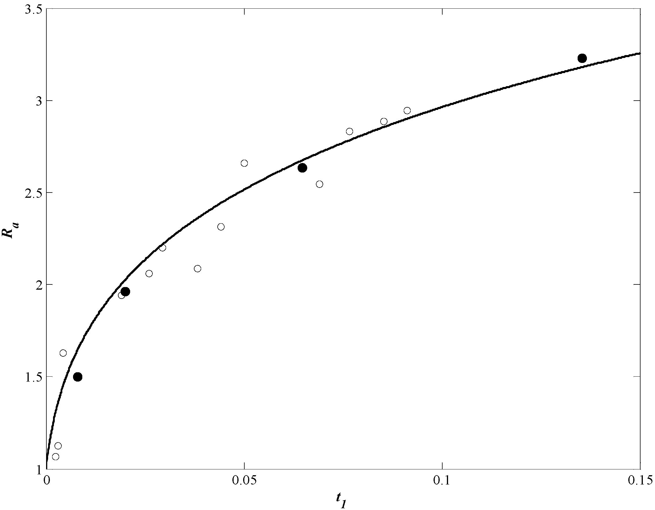
Evaluation of the accumulation radius over time is shown in Figure 3, where t * is “travelling time” [38]. The theoretical curve represents the graph calculated from Equation (8) as K = 800 . Experimental results from the literature [32,76,77] are shown in the same figure. As can be seen from Figure 3, the theoretical results obtained from Equation (8) are compatible with these experimental results. In addition, Equation (8) provides more straight variation of the accumulation radius reaching the saturation radius over time in case t .
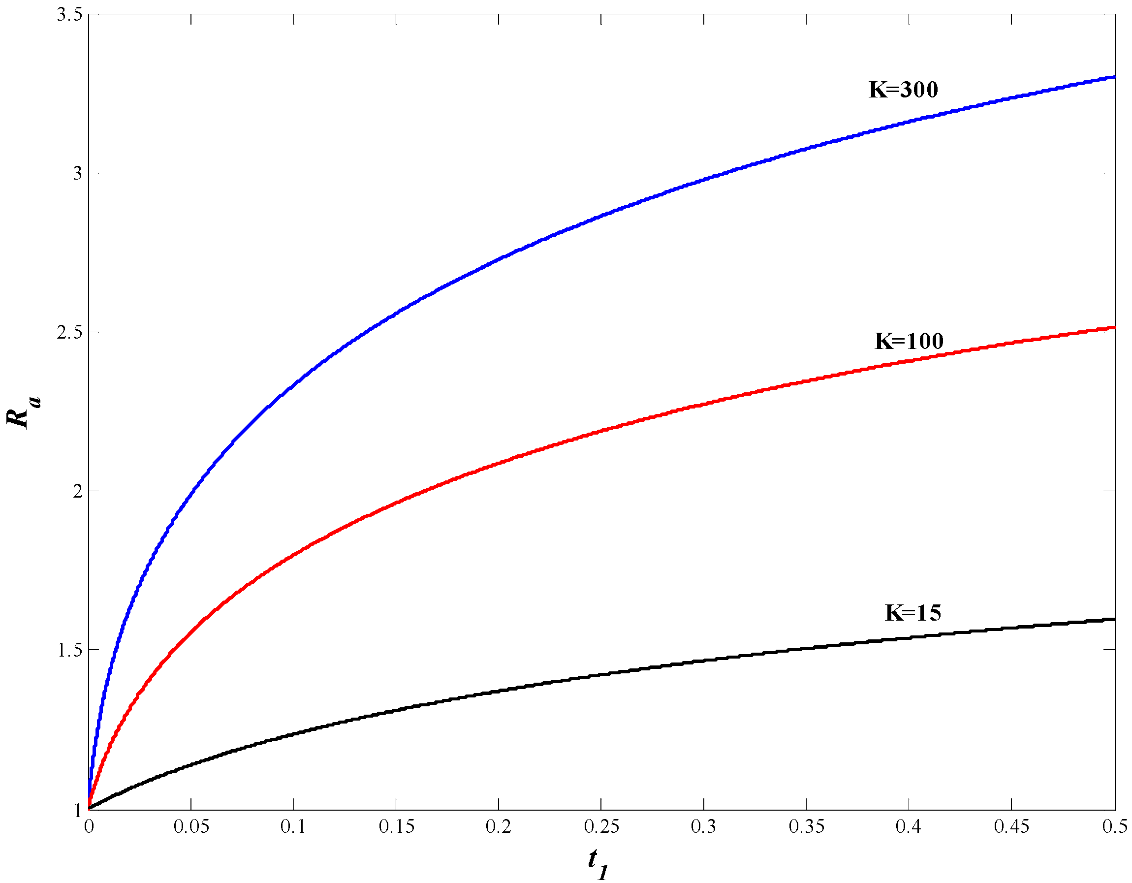
The flow of suspension is assumed only ideal or potential in some studies. In this case, the effect of viscosity on the accumulation of particles is essentially not considered. However, in several experimental studies [32], it has been proven that the effect of viscosity on the accumulation profile of particles is effective from the beginning of the capture process. In addition, the evolution of the accumulation profile over time also showed many differences [74,78,79,80] In Figure 4, the changes with time in the accumulation profiles at various K values calculated by Equation (8) for different viscosities are shown. The results from Figure 4 are generally in agreement with the experimental results of the accumulation profiles of M n 2 P 2 O 7 particles ( H = 5 k O e ,   C i = 0.4   g / L ) from glycerol solutions with different concentrations presented in [32]. Here, the K coefficient also changes with the change of viscosity. Some results of these changes of the K   coefficient are shown in Figure 4.
The evolution of the accumulation profile in axial flow over time is assumed to be either at the initial moment or in the steady state, in the form of increasing layers or approximately constant (Figure 2). In reality, this event is stochastic, shaped as rise and fall profiles along the wire. The stochastic evolution of the accumulation profile over time can be approximated using a simplified version of the Fokker–Planck equation. The distribution functions obtained from the solutions of Equation (11) or Equation (13) are obtained in the form of curves with a certain peak value [73]. Although the peaks of the distribution function are small at the beginning, these peaks become larger later in the separation. In addition, the increase and decrease curves of these graphs are in repeated form. These results show that in the evolution of the accumulation profile over time, the capture and detachment events of the particles are more dominant, and this event slows down and becomes stable over time. At the same time, in this process, the phenomenon of capture and detachment of the particles on the magnetized wire is repeated several times. Since the magnetic force is more effective in magnetic separation processes, the distribution function of the evolution of the accumulation profile over time can be expressed with curves that have a single peak value. In this case, the solutions of the Fokker–Planck equation and the population approach yield the same results (Equations (7) and (16)). Therefore, the obtained Equation (8) overlaps in principle with the fundamental studies in the literature [30,31,32,34,38,74] explaining the evolution of the accumulation of magnetic particles. Unlike these studies, Equation (8) allows evaluating the capture–detachment events of the particles in the evolution of the accumulation profile and the stochastic character of this event in the whole evolution process.

4. Conclusions

In this study, the differential equation of the time-dependent evolution of the accumulation of submicron-sized magnetic particles on a magnetized ferromagnetic wire in axial flow was developed. The kinetic equation of the development of the accumulation profile was studied by using two approaches based on the genetic population and Fokker–Planck stochastic equation. In these approaches, the formation of the accumulation profile can be evaluated by considering the possibilities of both capture and detachment of the particles. Unlike the conventional approaches presented in the literature for the deposition of particles in axial flow on the magnetized wire, in these approaches, the time-dependent evolution of the deposition profile of the particles can be examined not only for the initial moment but for all stages of the process. Since the distribution of the accumulation profile on the wire is generally a stochastic phenomenon, this change can also be examined according to the solution of the Fokker–Planck equation. Based on this solution, the development of the accumulation profile on the wire was observed with continuously repeated capture–detachment events. Although these events were more active in the beginning compared to the geometry of the magnetized wire, the stabilization of the accumulation profile became more noticeable in the later regions. The evolution of the accumulation profile over time in both approaches was evaluated using the kinetic coefficient, K . The K coefficient, which depends on the magnetic, geometric, hydrodynamic, rheological, and other physical properties of the system in magnetic separation processes, is defined as the ratio of the coefficients determining the capture ( K a ) and detachment ( K d ) of the particles, K = K a / K d . Approximate analytical methods or empirical formulas can be used to determine the K coefficient, which is the key parameter in both approaches presented in this study. On the other hand, after the particle capture coefficient, K a , is calculated according to Equation (3), presented in [31], the detachment coefficient, K d , can be easily evaluated based on the experimental statistical result of the saturation value of the build-up radius. The K d coefficient can be theoretically determined by using the balance of “adhesion force” [38] or from the balance of torque affecting particles in the steady-state structure of the accumulation profile [26].
In the separation processes, with K > 1 , it can be said that while the accumulation of particles by capturing is dominant at large values of K , not only the capture but also the detachment event is effective at low values of K . Moreover, in this process, the capture and detachment events of the particles can be repeated several times, or the breaking particles from the wire can be in motion without being caught again. K = 1 is the critical limit level of the separation process, and when K < 1 , the separation process does not take place in the system or the particles that have been previously captured on the wire break away from the wire. When t , the results of the build-up radius from both approaches are the same and the saturation value of the build-up radius in the accumulation profile is reached. This result is in good agreement with the theoretical and experimental results of the saturation value of the build-up radius presented in the literature. Unlike other studies, these approaches allow examining the build-up event of captured particles on the wire in the entire process.

Author Contributions

Conceptualization, H.B. and T.A.; Data curation, T.A.; Formal analysis, C.K. and T.A.; Investigation, T.A.; Methodology, H.B., C.K. and T.A.; Project administration, H.B.; Software, C.K.; Supervision, T.A.; Validation, T.A.; Visualization, H.B. and C.K.; Writing—original draft, C.K.; Writing—review & editing, H.B. and T.A. All authors have read and agreed to the published version of the manuscript.

Funding

This study was supported by Inonu University Scientific Research Projects Coordination Unit (BAP) within the scope of the project numbered FDK-2017-775.

Institutional Review Board Statement

Not applicable.

Informed Consent Statement

Not applicable.

Data Availability Statement

Not applicable.

Conflicts of Interest

The authors declare no conflict of interest.

References

  1. Watson, J.H. Magnetic filtration. J. Appl. Phys. 1973, 44, 4209–4213. [Google Scholar] [CrossRef]
  2. Oberteuffer, J. Magnetic separation: A review of principles, devices, and applications. IEEE Trans. Magn. 1974, 10, 223–238. [Google Scholar] [CrossRef]
  3. Oder, R. High gradient magnetic separation theory and applications. IEEE Trans. Magn. 1976, 12, 428–435. [Google Scholar] [CrossRef]
  4. Gerber, R.; Birss, R.R. High Gradient Magnetic Separation; Research Studies Press Division of John Wiley & Sons, Ltd.: London, UK, 1983; p. 209. [Google Scholar]
  5. Karmazin, V.; Karmazin, V. Magnetic Methods of beneficiation; Nedra Publishing: Moscow, Russia, 1984. [Google Scholar]
  6. Svoboda, J. Magnetic Techniques for the Treatment of Materials; Springer Science & Business Media: Berlin/Heidelberg, Germany, 2004. [Google Scholar]
  7. Kelland, D. High gradient magnetic separation applied to mineral beneficiation. IEEE Trans. Magn. 1973, 9, 307–310. [Google Scholar] [CrossRef]
  8. Parker, M.R. The physics of magnetic separation. Contemp. Phys. 1977, 18, 279–306. [Google Scholar] [CrossRef]
  9. Kolm, H.; Oberteuffer, J.; Kelland, D. High-gradient magnetic separation. Sci. Am. 1975, 233, 46–55. [Google Scholar] [CrossRef]
  10. Luborsky, F.; Drummond, B. High gradient magnetic separation: Theory versus experiment. IEEE Trans. Magn. 1975, 11, 1696–1700. [Google Scholar] [CrossRef]
  11. Yavuz, C.T.; Prakash, A.; Mayo, J.; Colvin, V.L. Magnetic separations: From steel plants to biotechnology. Chem. Eng. Sci. 2009, 64, 2510–2521. [Google Scholar] [CrossRef]
  12. Lindner, J.; Nirschl, H. A hybrid method for combining High-Gradient Magnetic Separation and centrifugation for a continuous process. Sep. Purif. Technol. 2014, 131, 27–34. [Google Scholar] [CrossRef]
  13. Gómez-Pastora, J.; Xue, X.; Karampelas, I.H.; Bringas, E.; Furlani, E.P.; Ortiz, I. Analysis of separators for magnetic beads recovery: From large systems to multifunctional microdevices. Sep. Purif. Technol. 2017, 172, 16–31. [Google Scholar] [CrossRef]
  14. Kefeni, K.K.; Mamba, B.B.; Msagati, T.A. Application of spinel ferrite nanoparticles in water and wastewater treatment: A review. Sep. Purif. Technol. 2017, 188, 399–422. [Google Scholar] [CrossRef]
  15. Wang, Z.; Liu, C.; Wei, W. Industry applications of magnetic separation based on nanoparticles: A review. Int. J. Appl. Electromagn. Mech. 2019, 60, 281–297. [Google Scholar] [CrossRef]
  16. Melville, D.; Paul, F.; Roath, S. Direct magnetic separation of red cells from whole blood. Nature 1975, 255, 706. [Google Scholar] [CrossRef]
  17. Paul, F.; Melville, D.; Roath, S.; Warhurst, D. A bench top magnetic separator for malarial parasite concentration. IEEE Trans. Magn. 1981, 17, 2822–2824. [Google Scholar] [CrossRef]
  18. Zborowski, M.; Chalmers, J.J. Magnetic Cell Separation; Elsevier: Amsterdam, The Netherlands, 2011. [Google Scholar]
  19. Häfeli, U.; Schütt, W.; Teller, J.; Zborowski, M. Scientific and Clinical Applications of Magnetic Carriers; Springer Science & Business Media: Berlin/Heidelberg, Germany, 2013. [Google Scholar]
  20. Šafařík, I.; Šafaříková, M. Use of magnetic techniques for the isolation of cells. J. Chromatogr. B Biomed. Sci. Appl. 1999, 722, 33–53. [Google Scholar] [CrossRef]
  21. Setchell, C.H. Magnetic separations in biotechnology—A review. J. Chem. Technol. Biotechnol. 1985, 35, 175–182. [Google Scholar] [CrossRef]
  22. Leong, S.S.; Yeap, S.P.; Lim, J. Working principle and application of magnetic separation for biomedical diagnostic at high-and low-field gradients. Interface Focus 2016, 6, 20160048. [Google Scholar] [CrossRef] [PubMed] [Green Version]
  23. Kelland, D.R. Magnetic separation of nanoparticles. IEEE Trans. Magn. 1998, 34, 2123–2125. [Google Scholar] [CrossRef]
  24. He, J.; Huang, M.; Wang, D.; Zhang, Z.; Li, G. Magnetic separation techniques in sample preparation for biological analysis: A review. J. Pharm. Biomed. Anal. 2014, 101, 84–101. [Google Scholar] [CrossRef]
  25. David, A.E.; Cole, A.J.; Chertok, B.; Park, Y.S.; Yang, V.C. A combined theoretical and in vitro modeling approach for predicting the magnetic capture and retention of magnetic nanoparticles in vivo. J. Control. Release 2011, 152, 67–75. [Google Scholar] [CrossRef] [Green Version]
  26. Abbasov, T. Some Actual Problems of Magnetic Filters With Magnetized Packed Beds and Comparative Analysis of Filter Performances. IEEE Trans. Magn. 2019, 55, 1–12. [Google Scholar] [CrossRef]
  27. Birss, R.; Gerber, R.; Parker, M.; Sheerer, T. Theory and performance of axial magnetic filters in laminar flow conditions. IEEE Trans. Magn. 1978, 14, 389–391. [Google Scholar] [CrossRef]
  28. Birss, R.; Gerber, R.; Parker, M. Theory and design of axially ordered filters for high intensity magnetic separation. IEEE Trans. Magn. 1976, 12, 892–894. [Google Scholar] [CrossRef]
  29. Gerber, R. Theory of particle capture in axial filters for high gradient magnetic separation. J. Phys. D Appl. Phys. 1978, 11, 2119. [Google Scholar] [CrossRef]
  30. Uchiyama, S.; Takayasu, M.; Kurinobu, S. Performance of Parallel Stream Type Magnetic Filter for High Gradient Magnetic Separation. Trans. Inst. Electr. Eng. Jpn. B 1977, 97, 459–466. [Google Scholar] [CrossRef]
  31. Uchiyama, S.; Kondo, S.; Takayasu, M.; Eguchi, I. Performance of parallel stream type magnetic filter for HGMS. IEEE Trans. Magn. 1976, 12, 895–897. [Google Scholar] [CrossRef]
  32. Uchiyama, S.; Kurinobu, S.; Kumazawa, M.; Takayasu, M. Magnetic particle buildup processes in parallel stream type HGMS filter. IEEE Trans. Magn. 1977, 13, 1490–1492. [Google Scholar] [CrossRef]
  33. Zheng, X.; Xue, Z.; Wang, Y.; Zhu, G.; Lu, D.; Li, X. Modeling of particle capture in high gradient magnetic separation: A review. Powder Technol. 2019, 352, 159–169. [Google Scholar] [CrossRef]
  34. Friedlaender, F.; Takayasu, M.; Rettig, J.; Kentzer, C. Particle flow and collection process in single wire HGMS studies. IEEE Trans. Magn. 1978, 14, 1158–1164. [Google Scholar] [CrossRef]
  35. Friedlaender, F.; Takayasu, M. A study of the mechanisms of particle buildup on single ferromagnetic wires and spheres. IEEE Trans. Magn. 1982, 18, 817–821. [Google Scholar] [CrossRef]
  36. Friedlaender, F.; Takayasu, M.; Rettig, J.; Kentzer, C. Studies of single wire parallel stream type HGMS. IEEE Trans. Magn. 1978, 14, 404–406. [Google Scholar] [CrossRef]
  37. Hoffmann, H.; Neudel, M.; Schewe, H.; Reffle, J. Trajectories of para-and freeomagnetic particles in HGMS filters with axial configurations. Appl. Phys. 1981, 24, 229–232. [Google Scholar] [CrossRef]
  38. Badescu, V.; Murariu, V.; Rotariu, O.; Rezlescu, N. A new modeling of the initial buildup evolution on a wire in an axial HGMF filter. J. Magn. Magn. Mater. 1996, 163, 225–231. [Google Scholar] [CrossRef]
  39. Wang, Y.; Xue, Z.; Zheng, X.; Lu, D.; Li, X.; Chu, H. Study on favorable matrix aspect ratio for maximum particle capture in axial high gradient magnetic separation. Miner. Eng. 2019, 135, 48–54. [Google Scholar] [CrossRef]
  40. Gurevich, A.; Beklemisheva, A.V.; Levada, E.; Rodionova, V.; Panina, L.V. Ferromagnetic Microwire Systems as a High-Gradient Magnetic Field Source for Magnetophoresis. IEEE Magn. Lett. 2020, 11, 1–5. [Google Scholar] [CrossRef]
  41. Rezlescu, N.; Murariu, V.; Rotariu, O.; Badescu, V. Capture modeling for an axial high gradient magnetic separation filter with a bounded flow field. Powder Technol. 1995, 83, 259–264. [Google Scholar] [CrossRef]
  42. Xue, Z.; Wang, Y.; Zheng, X.; Lu, D.; Li, X. Particle capture of special cross-section matrices in axial high gradient magnetic separation: A 3D simulation. Sep. Purif. Technol. 2020, 237, 116375. [Google Scholar] [CrossRef]
  43. Zheng, X.; Wang, Y.; Lu, D. Particle capture of elliptic cross-section matrices for parallel stream high gradient magnetic separation. COMPEL Int. J. Comput. Math. Electr. Electron. Eng. 2016, 35, 187–199. [Google Scholar] [CrossRef]
  44. Zheng, X.; Wang, Y.; Lu, D.; Li, X.; Li, S.; Chu, H. Comparative study on the performance of circular and elliptic cross-section matrices in axial high gradient magnetic separation: Role of the applied magnetic induction. Miner. Eng. 2017, 110, 12–19. [Google Scholar] [CrossRef]
  45. Kramer, A.; Janssen, J.; Perenboom, J. Single-wire HGMS of colloidal particles: The evolution of concentration profiles. IEEE Trans. Magn. 1990, 26, 1858–1860. [Google Scholar] [CrossRef]
  46. Takayasu, M.; Gerber, R.; Friedlaender, F. The collection of strongly magnetic particles in HGMS. J. Magn. Magn. Mater. 1983, 40, 204–214. [Google Scholar] [CrossRef]
  47. Abbasov, T.; Herdem, S.; Köksal, M. Particle capture in axial magnetic filters with power law flow model. J. Phys. D Appl. Phys. 1999, 32, 1097. [Google Scholar] [CrossRef]
  48. Köksal, M.; Abbasov, T.; Herdem, S. Mathematical modeling of the magnetic filtration processes. Int. J. Appl. Electromagn. Mech. 2003, 18, 227–234. [Google Scholar] [CrossRef]
  49. Hournkumnuard, K.; Natenapit, M. Diffusive capture of magnetic particles by an assemblage of random cylindrical collectors. Sep. Sci. Technol. 2008, 43, 3448–3460. [Google Scholar] [CrossRef]
  50. Hournkumnuard, K.; Natenapit, M. The capture of micro-particles by random cylindrical wires in axial magnetic filters. Sep. Sci. Technol. 2013, 48, 2234–2242. [Google Scholar] [CrossRef]
  51. Choomphon-anomakhun, N.; Ebner, A.D.; Natenapit, M.; Ritter, J.A. Simulation of dynamic magnetic particle capture and accumulation around a ferromagnetic wire. J. Magn. Magn. Mater. 2017, 428, 493–505. [Google Scholar] [CrossRef]
  52. Abbasov, T.; Gögebakan, V.; Karadağ, T. Particle capture modeling for an axial magnetic filter with a bounded non-Newtonian flow field. Powder Technol. 2016, 291, 223–228. [Google Scholar] [CrossRef]
  53. Schroen, K.; van Dinther, A.; Stockmann, R. Particle migration in laminar shear fields: A new basis for large scale separation technology? Sep. Purif. Technol. 2017, 174, 372–388. [Google Scholar] [CrossRef]
  54. Abbasov, T.; Bilgili, H.; Sarımeşeli Paçacı, A. Quasi-Newtonian Approach determination of velocity profile for the fully developed axial power law fluid flow in concentric annuli. Asia-Pac. J. Chem. Eng. 2021, 16, e2710. [Google Scholar] [CrossRef]
  55. Bilgili, H.; Abbasov, T. An Overview of Blood Analogues Used in Bioengineering (in Turkish). J. Inonu Univ. Health Serv. Vocat. Sch. 2020, 8, 946–963. [Google Scholar]
  56. Paul, F.; Melville, D.; Roath, S. Inviscid approximation trajectories in high gradient magnetic separation. IEEE Trans. Magn. 1982, 18, 792–795. [Google Scholar] [CrossRef]
  57. Gerber, R.; Takayasu, M.; Friedlaender, F. Generalization of HGMS theory: The capture of ultra-fine particles. IEEE Trans. Magn. 1983, 19, 2115–2117. [Google Scholar] [CrossRef]
  58. Gerber, R. Magnetic filtration of ultra-fine particles. IEEE Trans. Magn. 1984, 20, 1159–1164. [Google Scholar] [CrossRef]
  59. Takayasu, M.; Gerber, R.; Friedlaender, F. Magnetic separation of submicron particles. IEEE Trans. Magn. 1983, 19, 2112–2114. [Google Scholar] [CrossRef]
  60. Fletcher, D. Fine particle high gradient magnetic entrapment. IEEE Trans. Magn. 1991, 27, 3655–3677. [Google Scholar] [CrossRef]
  61. Yaniv, I.; Lin, I.J.; Zimmels, Y. Hydrostatic levitation of particles in electric and magnetic fields. Sep. Sci. Technol. 1979, 14, 557–570. [Google Scholar] [CrossRef]
  62. Luborsky, F.; Drummond, B. Buildup of particles on fibers in a high field-high gradient separator. IEEE Trans. Magn. 1976, 12, 463–465. [Google Scholar] [CrossRef]
  63. Murariu, V.; Rezlescu, N.; Rotariu, O.; Badescu, V. Concentration influences on recovery in a high gradient magnetic separation axial filter. IEEE Trans. Magn. 1998, 34, 695–699. [Google Scholar] [CrossRef]
  64. Zheng, X.; Wang, Y.; Lu, D. Study on buildup of fine weakly magnetic minerals on matrices in high gradient magnetic separation. Physicochem. Probl. Miner. Processing 2017, 53, 94–109. [Google Scholar]
  65. Murariu, V.; Rezlescu, N.; Rotariu, O.; Badescu, V. The effect of suspension concentration on the buildup evolution in a HGMF-axial magnetic filter. Eur. Phys. J. Appl. Phys. 1998, 1, 39–44. [Google Scholar] [CrossRef]
  66. Sobecki, C.; Zhang, J.; Wang, C. Dynamics of a Pair of Paramagnetic Janus Particles under a Uniform Magnetic Field and Simple Shear Flow. Magnetochemistry 2021, 7, 16. [Google Scholar] [CrossRef]
  67. Zhang, J.; Wang, C. Numerical study of lateral migration of elliptical magnetic microparticles in microchannels in uniform magnetic fields. Magnetochemistry 2018, 4, 16. [Google Scholar] [CrossRef] [Green Version]
  68. Shapiro, M.; Shalom, A. Particle buildup on a single rod in magnetic capture from axisymmetric flows. Physicochem. Hydrodyn. 1988, 10, 215–228. [Google Scholar]
  69. Badescu, V.; Rezlescu, N. On the possibility of HGMS filtration in the turbulent flow regime. Powder Technol. 1992, 73, 93–94. [Google Scholar] [CrossRef]
  70. Lasheras, J.C.; Eastwood, C.; Martınez-Bazán, C.; Montanes, J. A review of statistical models for the break-up of an immiscible fluid immersed into a fully developed turbulent flow. Int. J. Multiph. Flow 2002, 28, 247–278. [Google Scholar] [CrossRef] [Green Version]
  71. Herdem, S.; Abbasov, T.; Köksal, M. Modelling of the buildup process of particles in pores of high-gradient magnetic filters using the Fokker-Planck equation. J. Phys. D Appl. Phys. 1999, 32, 3146. [Google Scholar] [CrossRef]
  72. Gardiner, C.W. Handbook of Stochastic Methods, 3rd ed.; Springer: Berlin/Heidelberg, Germany, 2004. [Google Scholar]
  73. Kelbaliyev, G.; Tagiyev, D.B.; Rasulov, S.R. Transport Phenomena in Dispersed Media; CRC Press: Boca Raton, FL, USA, 2019. [Google Scholar]
  74. McNeese, W.; Wankat, P.; Friedlaender, F.; Nakano, T.; Takayasu, M. Viscosity effects in single wire HGMS studies. IEEE Trans. Magn. 1979, 15, 1520–1522. [Google Scholar] [CrossRef]
  75. Takayasu, M.; Friedlaender, F.; Jeong, K.; Petrakis, L. High gradient magnetic separation II: Single wire studies of shale oils. IEEE Trans. Magn. 1982, 18, 1695–1697. [Google Scholar] [CrossRef]
  76. Cowen, C.; Friedlaender, F.; Jaluria, R. Single wire model of high gradient magnetic separation processes II. IEEE Trans. Magn. 1976, 12, 898–900. [Google Scholar] [CrossRef]
  77. Cowen, C.; Friedlaender, F.; Jaluria, R. Single wire model of high gradient magnetic separation processes I. IEEE Trans. Magn. 1976, 12, 466–470. [Google Scholar] [CrossRef]
  78. Kurinobu, S. Buildup of magnetic flocs containing plankton on a single wire. IEEE Trans. Magn. 1987, 23, 2770–2772. [Google Scholar] [CrossRef]
  79. Liu, Q.; Fridlaender, F. Selective collection of non-magnetic rutile and quartz by means of a magnetic reagent by HGMS. IEEE Trans. Magn. 1994, 30, 4668–4670. [Google Scholar]
  80. Wankat, P.; Hwang, J.; Beckemeyer, D.; Friedlaender, F. Removal of paramagnetic particles from single wire HGMS. IEEE Trans. Magn. 1984, 20, 1177–1179. [Google Scholar] [CrossRef]
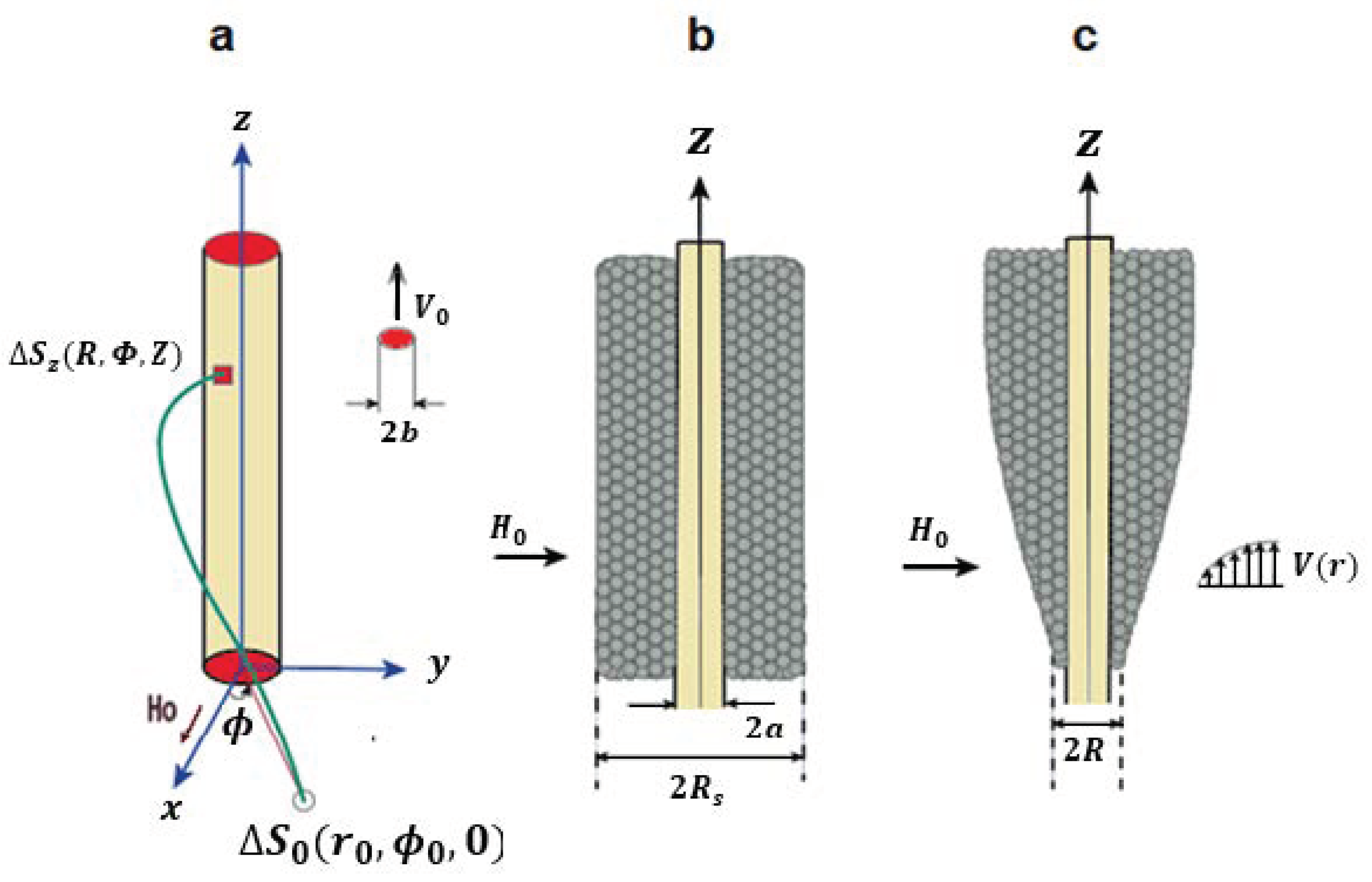
Figure 1. Principal schema of axial particle-capturing and build-up systems: (a) particle capture, (b) particle build-up at high Reynolds number, (c) particle build-up at low Reynolds number.
Magnetochemistry 08 00015 g001
Figure 2. Variation of non-dimensional changes of R R s = f ( t 1 ) at different K 1   values.
Magnetochemistry 08 00015 g002
Figure 3. Evaluation of accumulation radius over time: symbols, test results [32]. Magnetochemistry 08 00015 i001:   M n 2 P 2 O 7 particles δ = 10 20   μ m ,   H 0 = 12.5   k O e ,   Magnetochemistry 08 00015 i002: α F e 2 O 3 particles δ = 2   μ m ,   H 0 = 11   k O e , and theoretical curve calculated based on Equation (8), K = 800 , t 1 = 0.5 · 10 2 t * ( t * is “travelling time” of capturing particles [32,38]).
Magnetochemistry 08 00015 g003
Figure 4. The effect of the viscosity of the medium carrying the magnetic particles on the change of the accumulation radius, t 1 = 0.5 · 10 2 t * .
Magnetochemistry 08 00015 g004
Publisher’s Note: MDPI stays neutral with regard to jurisdictional claims in published maps and institutional affiliations.