Article

An Improved 3D Magnetization Inversion Based on Smoothness Constraints in Spherical Coordinates

1
School of Geosciences and Info-Physics, Central South University, Changsha 410083, China
2
Hunan Key Laboratory of Nonferrous Resources and Geological Hazards Exploration, Changsha 410083, China
3
Key Laboratory of Metallogenic Prediction of Nonferrous Metals and Geological Environment Monitoring, Central South University, Ministry of Education, Changsha 410083, China
4
School of Resources & Environment and Safety Engineering, Hunan University of Science and Technology, Xiangtan 411201, China
*
Author to whom correspondence should be addressed.
Magnetochemistry 2022, 8(11), 157; https://doi.org/10.3390/magnetochemistry8110157
Submission received: 30 September 2022 / Revised: 8 November 2022 / Accepted: 10 November 2022 / Published: 14 November 2022
(This article belongs to the Special Issue Advances in Magnetotelluric Analysis)

Abstract

:
In the inverse problem, the traditional way to obtain a stable solution is based on the maximum smoothness criteria. However, this approach cannot generate clearer and more focused images. In this study, we propose an improved inversion method based on the smoothness constraints. In the algorithm, the model weighting functions are updated by adding a model’s total gradient module matrix, which can effectively constrain the boundary of the recovery model in the iterative operation. We invert the 3D magnetization intensity for the three-component magnetic data in the spatial domain by spherical coordinates. The preconditional conjugate gradient algorithm is introduced to improve the efficiency of the solutions. We design two sets of synthetic examples to evaluate the inversion effects, which show that the improved method is more reliable than the smoothness constraint method. The boundary of the magnetic bodies is more precise, and the magnetization ranges are more focused. The method does not rely on the initial model and is suitable for magnetic vector data inversion. We also apply the algorithm to a set of Dabie orogen three-component magnetic data derived from a geomagnetic field model and verify the effectiveness of the inversion method.

1. Introduction

The successive launches of CHAMP, GRACE, GOCE, Swarm, and other potential field-observing satellites have brought unprecedented opportunities and challenges to the processing and applications of gravity and magnetic data. Several high-order geomagnetic field models were developed, such as NGDC-720 and EMM2015, compiled from different data sources (satellite, oceanic, aeromagnetic, and geomagnetic survey data). The magnetic data derived from the models are one of the powerful instruments for the regional tectono-geophysical investigation of the Earth’s crust and upper mantle [1], and are being increasingly mapped for large regions geological analysis [2,3,4,5,6].
Another application for magnetic data is 3D physical property (magnetization or susceptibility) inversion, which visually outlines the spatial shapes and distributed features of magnetic field sources [7,8,9,10]. As one of the main physical property inversion methods, a considerable amount of in-depth research has been conducted regarding 3D magnetization intensity inversion techniques. Wang et al. [11] proposed a total magnetization vector inversion method to invert 2D layered models, and obtained the magnitude and direction of the magnetization. In another related study, Liu et al. [12] carried out magnetization vector inversion research on 2D borehole magnetic survey data. Furthermore, various researchers have determined the three-dimensional distribution features of magnetization based on magnetic anomaly amplitude data [13,14]. The magnetization intensity inversion methods of those spatial domains are generally carried out in Cartesian coordinates. They are not directly applicable to the inversion of global magnetic data, which are inherently in the spherical coordinates. The inversion methods extended to the spherical coordinates provide technical support for regional physical property inversion [8,15,16,17,18]. It is necessary to develop an applicable magnetization intensity inversion method to adapt to the rapidly increasing satellite-derived magnetic data.
The inverse problem in spherical coordinates is similar to that in Cartesian coordinates. One of the difficulties that the inverse problem faced was the non-uniqueness of the model. Many methods have been proposed to solve this problem in the Cartesian coordinates. These methods included smooth and small model inversion [19,20], focusing inversion [21,22], cokriging [23,24], binary and multinary inversion [25,26], and c-means clustering [27]. The available methods showed that they could decrease the non-uniqueness of models. Additionally, one possible solution to solve the problem is to adopt the Occam inversion method [28], which is developed based on Tikhonov regularization [29]. It is less dependent on the initial models and is now widely used in gravity and electromagnetic research [30,31]. This method can determine the smoothest solution for multi-layered geophysical models. The roughness of a model is minimized under a certain standard of a misfit. Due to the inherent properties of the method, the border of recovered models is not clear, and the images are not focused, which may be inapplicable under some geological issues. We propose an improved inversion method to improve the situation and describe it in detail later.
The magnetic data derived from geomagnetic field models are the magnetization responses generated at the lithospheric scale. Little is known about the remnant magnetization structures in the Earth’s continents. The induced magnetization and remnant magnetization in the magnetic anomalies of the continental crust cannot be decoupled/distinguished effectively [32,33]. Compared with the oceanic crust, the induced magnetic anomalies in the continental crust usually play major roles, and the remnant magnetization is usually ignored [34,35,36]. Moreover, due to many observation grids, field source space cells, and magnetic parameters, the regional magnetization intensity inversion in the spherical coordinates will be very time-consuming. Consequently, it can be considered that the lithospheric magnetic field is mainly dominated by induced magnetization to simplify the parameter space of the models and actual data.
The remainder of this paper is as follows: we first review the forward modeling and inversion of the magnetic problem in spherical coordinates and propose an improved inversion method based on the smoothness constraints. The third section evaluates the method with two synthetic examples of regional models. We apply the method to the magnetic vector data of the Dabie orogen to test the actual application effect in the fourth section. Finally, in the fifth section, we present the conclusions of this study.

2. Methodology

2.1. Forward Modeling in Spherical Coordinates

Different calculation methods can obtain magnetic potential field responses. In space domain magnetic vector forwarding methods, the magnetic potential and vector fields were usually directly calculated based on the magnetic dipole effects [37,38,39]. Blakely [40] proposes an alternative to link the magnetic potential and vector fields with the gravitational fields, referred to as Poisson’s relation. The two means were determined to be mathematically equivalent. We adopted the second method to obtain the magnetic vector field. We have to consider the gravitational potential and related derivatives calculations for the first step.
The gravitational potential V P of a solid body with volume Ω and density ρ at the observation point P outside of Ω is given by Newton’s integral [41]
V P = G ρ Ω 1 d Ω
The numerical evaluations of Equation (1) rely on mass discretization. It is needed to discretize the model’s underground space into a specific geometric shape and density. Using prisms is especially beneficial for local applications in Cartesian coordinates. For larger application areas, the Earth’s curvature has to be taken into account. It has been determined that a tesseroid model (Figure 1) with a constant height delineated by geographic grid lines, which are directly linked to the curvature of the Earth, is an ideal volume unit for forwarding.
The gravity potential based on tesseroid model has no analytical solution; it must be calculated approximately by integral method. There are mainly two kinds of algorithms: Gauss Legendre Quadrature (GLQ) and Taylor series expansion method based on integral kernel function. Ku [42] determines the distribution of anomalies using the least squares method based on equivalent point- mass. The interference point- mass in the anomaly body can be estimated according to the GLQ in the gravity field expression. He proposes an empirical standard in the method, that is, the distance between the points is not greater than the distance to the calculated point, and the accuracy of the solution basically remains unchanged. M. F. Asgharzadeh et al. [43] give an efficient and high-precision calculation method for gravity potential, gravity field, and gravity tensor of spherical unit body under the standard of Ku [42]. The minimum number of nodes can be given during calculation, and the distance to the observation points is greater than the nodes spacing, which reduces the number of calculation units and improves the efficiency. However, when the calculation point is close to the tesseroid element, the solutions of GLQ are unstable. Heck and Seitz [44] compare the gravity field calculation approaches of tesseroid, prism and point-mass. The third-order Taylor series expansion of the integral kernel function is carried out to approximate the gravity potential and its radial derivative. The results show that the zero-order form is equivalent to the formula of the point- mass, and the calculation efficiency and accuracy of the tesseroid are higher than those of the other two elements. To some extent, tesseroid has advantages in calculating the gravitational field.
A tesseroid is composed of radial, latitude, and longitude r , ϕ , λ , which was used to calculate the potential field and gradient tensors in the spherical coordinates. The gravitational potential, gravitational acceleration, and Marussi tensor, respectively, generated by the homogeneous body at the observation point P were described by
V P g α P g α β P = G ρ λ 1 λ 2 ϕ 1 ϕ 2 r 1 r 2 1 3 2 Δ α 3 Δ α Δ β 2 δ α β κ d r d ϕ d λ
where
Δ x = r cos ϕ sin ϕ sin ϕ cos ϕ cos λ λ Δ y = r cos ϕ sin λ λ Δ z = r cos ψ r
α , β x , y , z , in which x , y , z -, respectively, represent the north- east- up direction of the local north-oriented frame (LNOF), = r 2 + r 2 2 r r cos ψ , κ = r 2 cos ϕ , and δ α β are Kronecker’s Delta, and cos ψ = sin ϕ sin ϕ + cos ϕ cos ϕ cos λ λ .
We adopted the Gauss- Legendre quadrature (GLQ) integral to calculate the gravity field and gradient tensors [44,45] and truncated the order of each component of the GLQ to 2 to improve the calculating efficiency.
According to Poisson’s relation [40], an object with uniform magnetization and uniform density has the following relation between the magnetic vector B and Marussi tensor T
B = C m T M
where
T = g x x r P , ϕ P , λ P g x y r P , ϕ P , λ P g x z r P , ϕ P , λ P g y x r P , ϕ P , λ P g y y r P , ϕ P , λ P g y z r P , ϕ P , λ P g z x r P , ϕ P , λ P g z y r P , ϕ P , λ P g z z r P , ϕ P , λ P
the constant C m = μ 0 / 4 π G ρ , in which G = 6.674 × 10 11 m 3 kg 1 s 2 is the gravitational constant and μ 0 = 4 π × 10 7 H m 1 is the magnetic permeability of the free space, M = M x M y M z T refers to a matrix or vector composed of three orthogonal components of total magnetization intensity M .
The relations among each component of the M , magnetic inclination I , and magnetic declination A were as follows
M x = M cos I cos A M y = M cos I sin A M z = M sin I
Here, when only considering the induced magnetization of the magnetic body, I indicates the local geomagnetic inclination, and A is the angle between the direction of the magnetization direction and the magnetic north.
Based on the principle of superposition, the effect of the whole magnetization distribution can be approximated by the sum of the impact over all individual magnetic bodies. The parameterized forward modeling problem is expressed as
d = G m
where, d is the n dimensional data vector of observed magnetic anomaly, m is the m dimensional magnetization vector, and G refers to the nonlinear function that maps parameters m to magnetic field data d , which is expressed as the forwarding kernel matrix of the n × m size.

2.2. Occam Inversion Method

The general form of constructing the objective function and minimizing it can be described as
min : Γ m = ϕ d m + λ ϕ m m
where the Lagrange multiplier λ is the regularization factor of the preconditioned conjugate gradient (PCG) algorithm to balance the data misfit function ϕ d m and the model objective function ϕ m m .
We introduced a weighting function, and the re-weighted data misfit function was expressed as the 2 norm of the observed and predicted data
ϕ d m = Δ d G Δ m T W d T W d Δ d G Δ m
where Δ d is the corresponding modification of the observed data column vector, Δ m = m m r e f represents the modification of the model parameter vector m to the initial reference model m r e f , and W d = d i a g 1 / σ 1 , 1 / σ 2 , , 1 / σ m refers to the data space weighted matrix, which is a normalized diagonal matrix representing the standard deviation of the i - t h observation data.
In order to ensure that the model is smooth in three spatial directions, it is necessary to select a suitable model objective function to impose constraints on the inversion model. Li and Oldenburg [19] and Li [46] designed the model objective functions of the maximum smoothing method. However, those functions were only applicable to the Cartesian coordinates. Du et al. [8] and Liang et al. [15] introduced the smoothest model objective functions into the spherical coordinates. Considering the offset effects of the recovered models relative to the reference models on the sphere, we introduced a weighting function to constrain the models smoothly. Constructing the model objective functions as
ϕ m m = α s v w r Δ m 2 d v + α r v w r Δ m r 2 d v + α ϕ v w r Δ m r ϕ 2 d v + α λ v w r Δ m r cos ϕ λ 2 d v
where α s represents the weighting function of the minimum model constraint, α r , α ϕ , α λ is the relative weighting of the smoothest model objective function along three different directions on the sphere. In particular, w r indicates the radial weighting function.
In the unconstrained inversion of the potential field data, the kernel functions are attenuated sharply with increased depth. It will cause the recovered model to be concentrated near the surface. Li and Oldenburg [19,20] first introduced the depth weighting function w z = z + z 0 β / 2 into the model constraint terms of 3D gravity and magnetic inversions to overcome the attenuation effect. They applied it in 3D magnetic susceptibility imaging. Du et al. [8], Liang et al. [15], and Wang et al. [16], respectively, extended the depth weighting function to spherical coordinates and proposed different radial weighting functions. We used the radial weighting function of Wang et al. [16] as follows
w r = 1 H + R r β 2 r R
where R = 6371.2 km is the average radius of the Earth, H is the average height of the observation point, and r refers to the radial distance from the center of the model cell to the center of the Earth.
After that, the finite difference was substituted for the partial differential to discretize the model objective function, which could be described as a matrix
ϕ m m = Δ m T W s T W s + W r T W r + W ϕ T W ϕ + W λ T W λ Δ m = Δ m T W m T W m Δ m
where W m = α m R m D represents the weighted matrix after discretization: α m is the weighting coefficient of each item in the model objective function, R m indicates the differential operator along each direction of ( r , ϕ , λ ) , and D refers to the discrete matrix of the radial weighting function.
The data misfit and the model objective function were substituted into the objective function, which was expressed as
Γ m = Δ d G Δ m T W d T W d Δ d G Δ m + λ Δ m T W m T W m Δ m
The expression could be written as
G λ W m Δ m = d 0
Let A = G λ W m represent the Jacobian Matrix b = d 0 , and Equation (12) could be simplified to
A Δ m = b
The inversions of three-component magnetic anomalies come down to solving Equation (13), whose coefficient matrices are symmetric and positive-definite. The convergence speed of Equation (13) is determined by the condition numbers of the coefficient matrices. However, the condition numbers of the coefficient matrices are generally huge, which may seriously affect the computational efficiency of iterative convergence. This problem can be solved by indirect (iterative) methods such as the conjugate gradient (CG) method [47]. It has been found that the CG method is very effective in solving large-scale linear equations and is widely used in geophysical inversion processes [48,49,50]. The CG method combines the gradient direction and the conjugate direction. It searches for the optimal solution along a set of conjugate directions constructed by the gradient of the initial point.
We adopted the PCG algorithm in the matrix operation, which was developed based on the CG method. The preconditioned matrix was utilized to improve the condition numbers of the equations, and both ends of the equation were multiplied by the preconditioned matrix [48]. By implementing the approaches mentioned above, the eigenvalues of Equation (13) were concentrated along the diagonal, thereby improving the iteration efficiency.

2.3. Improved Inversion Method

In the regularization method, the general scheme to obtain the solution under certain conditions is to constrain the regularization terms. Many model constraint methods are proposed to obtain a suitable solution. These methods include minimum norm constraint [29], compact constraint [51], minimum moment of inertia constraint [52], minimum gradient constraint [21], and convexity constraint [53]. In this study, we need to obtain a stable solution and expect to effectively describe the boundary of the geological body.
In the minimum moment of the inertia constraint method, the weighting matrix W m is made of a reference model that model parameters are headed toward it during the iterative inversion process. Inspired by this method, we consider constraining and processing the weighting matrix of Occam’s model objective function. However, this process is not carried out directly on the weighting matrix. The first step is to calculate the total gradient module of the reference model
m ^ = m r 2 + m r ϕ 2 + m r cos ϕ λ 2
The updated weighting matrix is expressed as the inner product of two matrices
W ^ m = W m K m
where K m = d i a g m ^ 1 , m ^ 2 , , m ^ m γ is a diagonal matrix.
Finally, Equation (15) was substituted into Equation (11) for iterative calculation.

3. Synthesis Model Analysis

3.1. Models’ Geometry and Magnetic Parameters

Two sets of synthesis models were utilized to test the effectiveness of the inversion method. The first set included two hexahedron models with the same magnetic parameters (Models A and B). The second set included four hexahedron models with different magnetic and geometric parameters (Models C, D, E, and F). The model’s parameters and 3D visualization are shown in Table 1 and Figure 2. The height of forwarding calculations was set as 4 km, and the observational grid size measured 0.1 ° × 0.1 ° . During the inversion process, the field source spaces were subdivided into tesseroid models, and the sizes of the subdivided cells were 0.1 ° × 0.1 ° × 5 km. The total magnetization intensity is 10 A m 1 .

3.2. Analysis of Inversion Results

3.2.1. Synthesis Model of the Same Magnetic Parameters
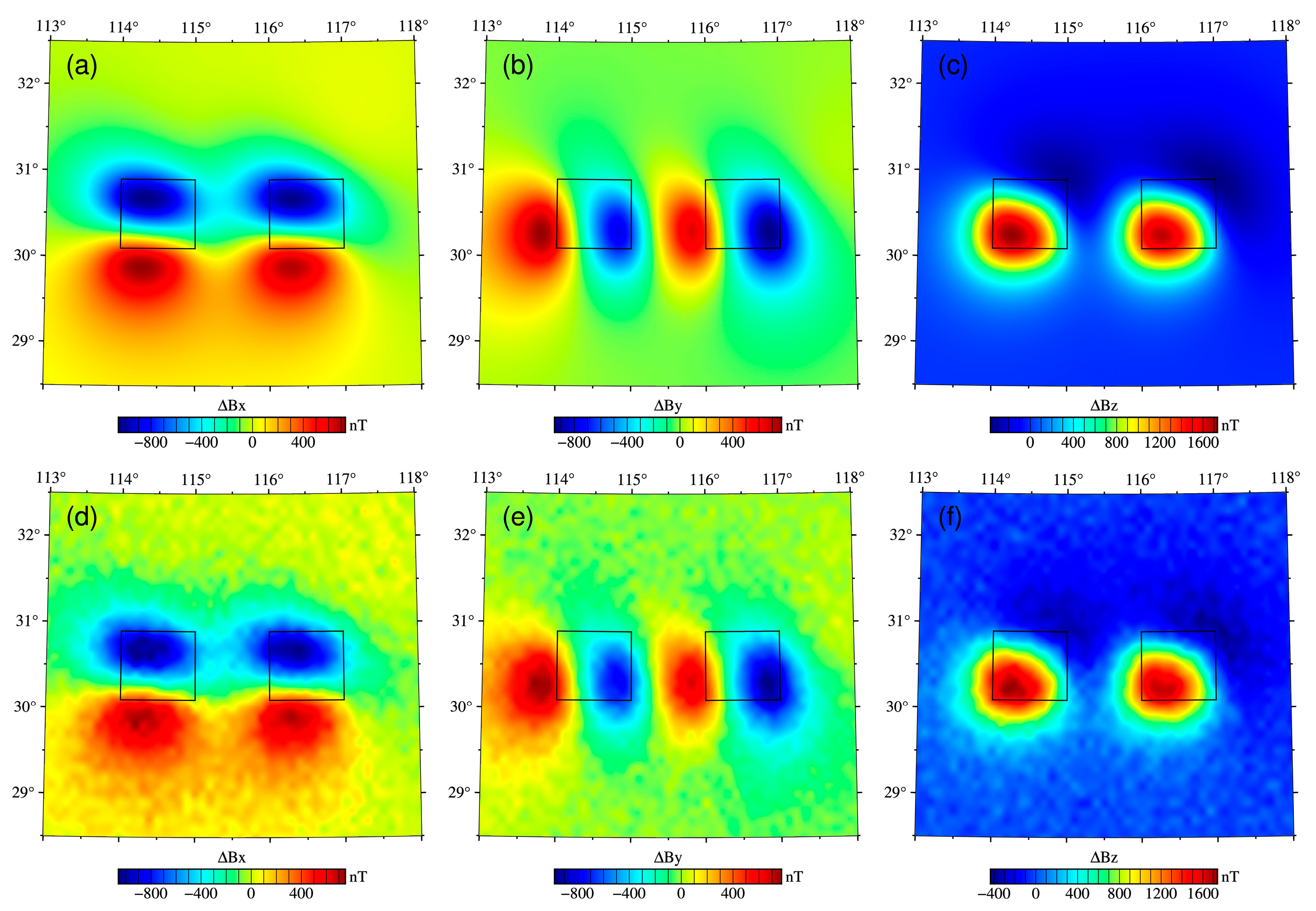
Figure 3 describes the three-component magnetic anomalies of the first set of models. Figure 4 and Figure 5 detail the magnetization imaging results of the Occam method and the improved method, respectively. The inversion results of the Occam method indicate that the magnetization boundary is fuzzy, and the field source range is difficult to define. The imaging results of the improved method can fit the actual model better. The magnetization ranges are relatively focused, and the field source’s boundaries are clear.
The two methods are both robust in the presence of noise. Some tiny false magnetic sources appeared near the surface of Δ B x - component and Δ B y - component imaging results.
It should be noted that the values obtained by both inversion methods deviate several times from the design models. The main reason is affected by the volume effect. Other reasons are that the recovered magnetic sources are still not focused enough (especially in the depth direction), and the model space is not finely divided. In comparison, the imaging results of the improved method are closer to the actual values.
Figure 3. Three-component magnetic anomalies, Δ B x , Δ B y , and Δ B z , of the first set of models: (ac) cases with noise-free; (df) cases with 5% noise signal. The black borders represent the position of the actual models.
Magnetochemistry 08 00157 g003
Figure 4. The inversion results (the profile at latitude = 30.5°) for three-component magnetic anomalies using the Occam method: (ac) the inversion results for Δ B x , Δ B y , and Δ B z of noise-free; (df) the inversion results for Δ B x , Δ B y , and Δ B z with 5% noise signal.
Magnetochemistry 08 00157 g004
Figure 5. The inversion results (the profile at latitude = 30.5°) for three-component magnetic anomalies using the improved method: (ac) the inversion results for Δ B x , Δ B y , and Δ B z of noise-free; (df) the inversion results for Δ B x , Δ B y , and Δ B z with 5% noise signal.
Magnetochemistry 08 00157 g005

3.2.2. Synthesis Model of Different Magnetic Parameters

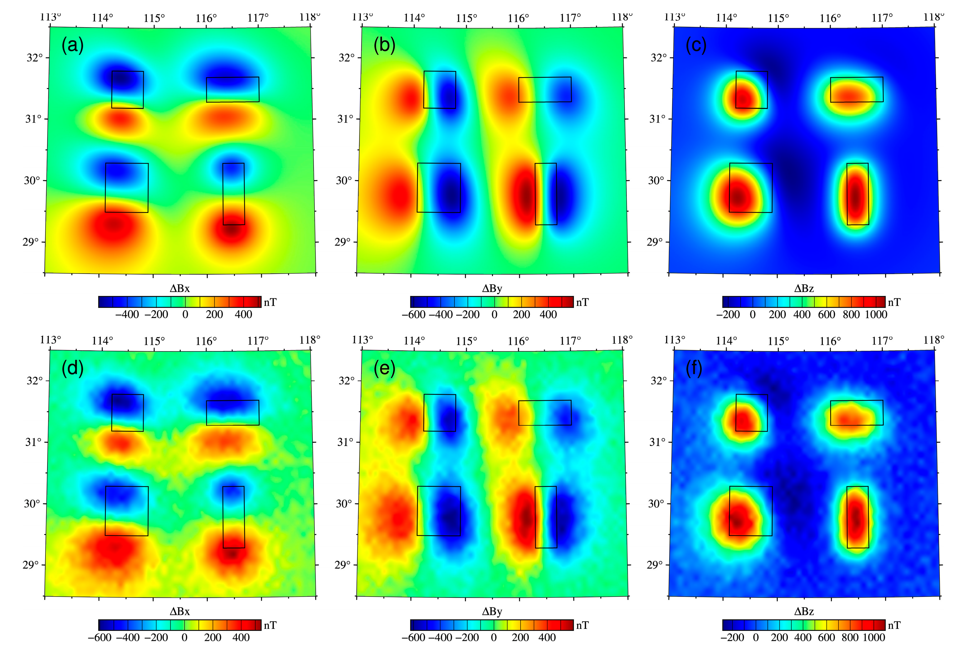
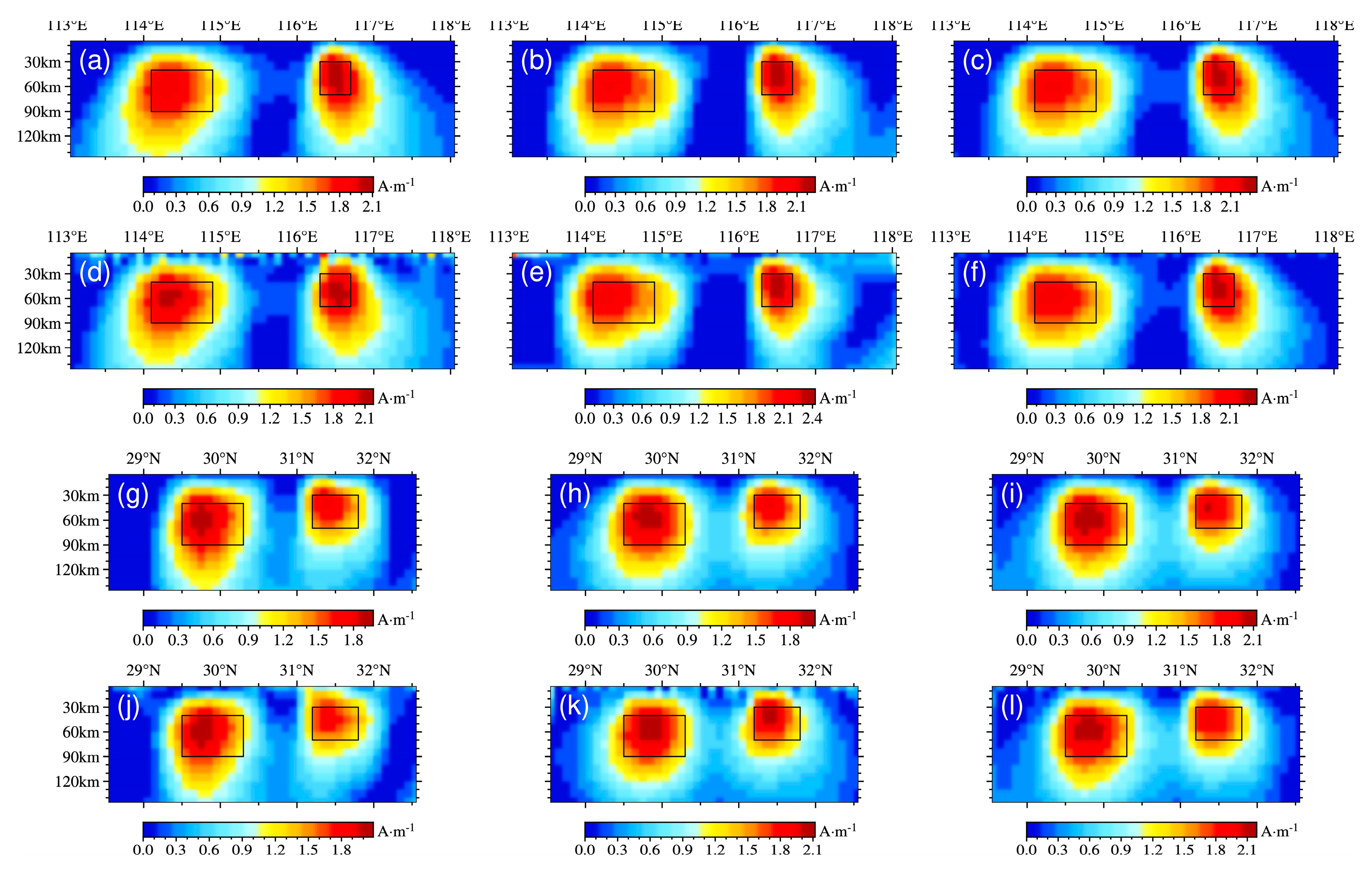
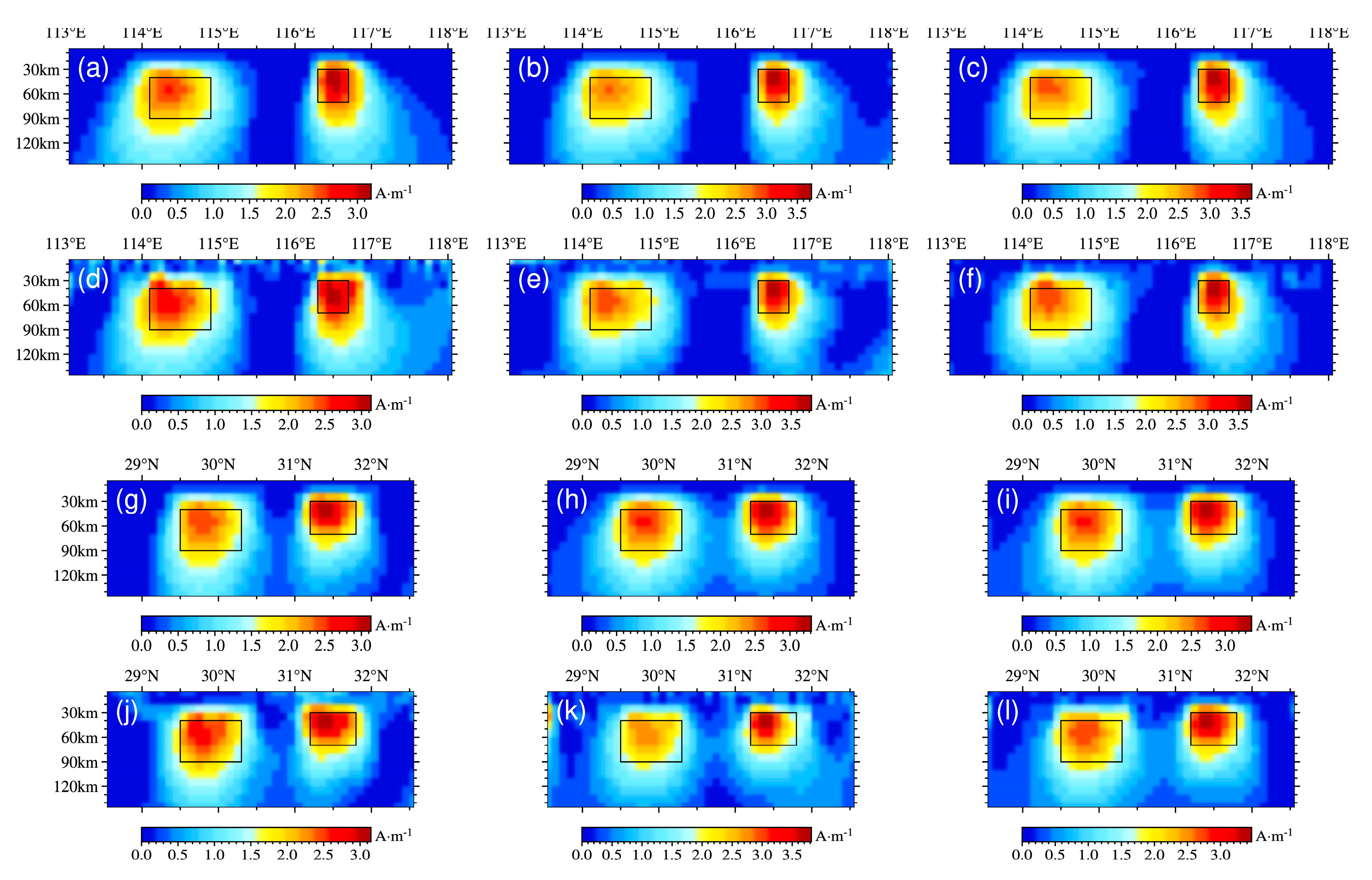
We still need to test the anti-noise ability of both inversion algorithms in the second set of models. The 5% noise signal was added to the magnetic three-component anomalies, and the noise levels are as shown in Figure 6, Figure 7 and Figure 8 are the magnetization imaging results of the Occam method and the improved method, respectively. In both figures, (a) to (f) are the vertical slices of the latitude directions, and (g) to (l) are the vertical slices of the longitude directions.
Comparing the imaging effects of the two inversion methods, the inversion results based on the improved method are in better agreement with the designed actual models. The ranges of magnetization distribution are small, and the properties boundaries are clear. The imaging result of the Occam method has a lower resolution, especially in the depth direction.
Similar to the conclusions of the first set of models, the magnetization intensity values of the actual model are several times higher than those obtained by the two inversion methods. The inversion results of the improved method are closer to the actual model. Noise has little effect on the Δ B z -component.
Overall, the improved inversion method clarifies the recovered magnetic model boundary and improves the depth resolution. For the three-component magnetic data, the inversion results of the vertical component are relatively stable.
In the model test, we obtained a group of weighted parameters ( β takes 3, γ is 0.5) with good results, and used the same parameter values for the following magnetic data inversion.

4. Magnetic Data Tests

The Dabie orogen is located in the middle section of the Qinling- Dabie- Sulu orogen in China, which is formed by the subduction of the northern margin of the South China Craton during the Triassic period and the continental collision with the North China Craton [54,55]. It is one of the largest high-pressure (HP) and ultrahigh-pressure (UHP) metamorphic rock belts worldwide. The orogen is composed of a series of metamorphic units bounded by faults (Figure 9). Tectonically, the NE- SW striking fault zone F6 divides the orogen into eastern Dabie and western Dabie. Four metamorphic units are further divided in eastern Dabie: northern Huaiyang (NHY) tectonic belt, northern Dabie complex unit, UHP metamorphic belt, and HP metamorphic belt. The NHY and HP belts are two relatively low-grade metamorphic rock units. Within the orogen, the rock types are mainly lower-degree to higher-degree metamorphic rock.
Many deep seismic investigations, electromagnetic explorations, and experimental gravity studies have been carried out to reveal the deeper physical properties information of the lithosphere. Seismic refraction profile results [57] show that the crust can be divided into upper, middle, and lower layers according to the velocity difference, and the thickness of the crust gradually increases from 35km in the south to 41km in the north. From the results of gravity spectrum analysis [58], there is obvious lateral heterogeneity in the middle and upper crust of the orogen. The inversion result of the magnetotelluric profile [59] shows that there are several isolated high-conductivity anomaly bodies in the middle crust. To sum up, there are low-density, high-resistivity, and low-velocity anomalies in Dabie orogen. However, researches regarding the lithospheric magnetic structures is still lacking. Yang and Li [58] previously used continuous wavelet transform to delineate two magnetic sources based on the total field magnetic anomalies along the profile line (the white line of dashes in Figure 10), which provided a basis for the comparative study in the area.
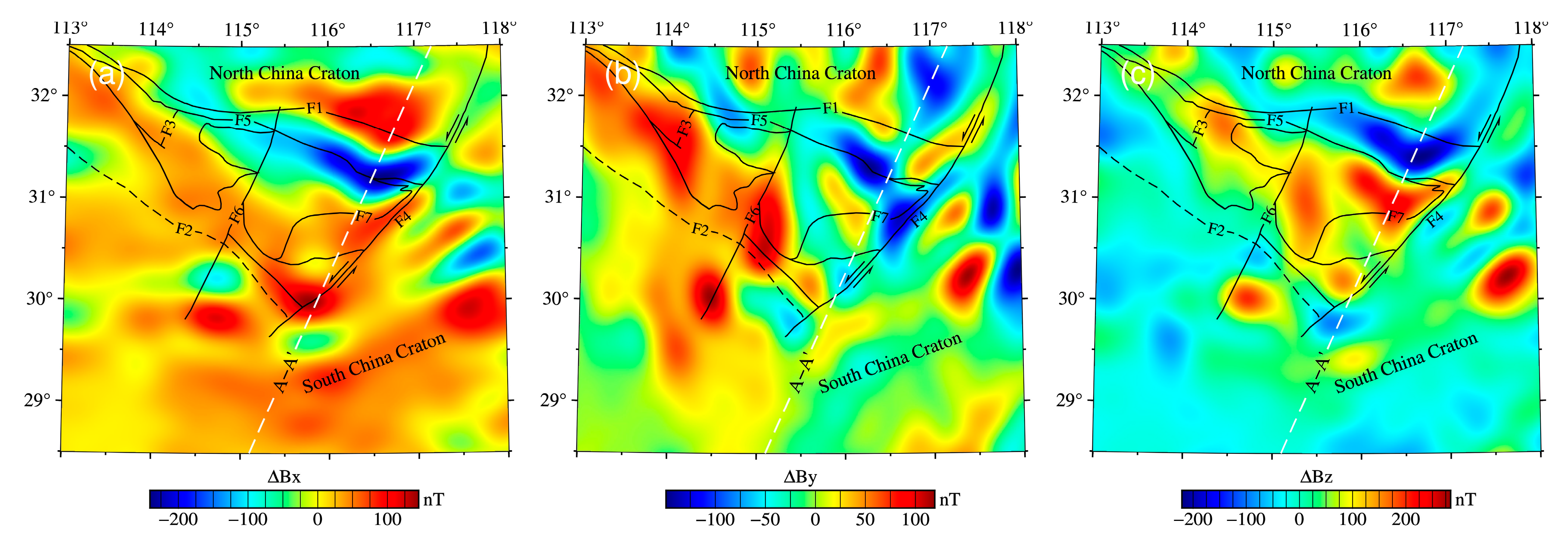
The lithospheric three-component magnetic anomalies of the Dabie orogen have been calculated at an aeromagnetic altitude (Figure 10). The magnetic survey datasets came from EMM2017 (Enhanced Magnetic Model, data can be found online: https://www.ngdc.noaa.gov/geomag/EMM/index.html, accessed on 1 September 2022). Spherical harmonic functions of the model are up to the orders of 790; that is, the spatial resolution is about 0.25 degrees. Moreover, the resolvable spatial wavelength is as fine as 51 km. The method used to calculate the lithosphere’s magnetic anomalies included stripping the core magnetic field (orders n 15 ) from the total magnetic field [60]. The observational grid size measured 0.1 ° × 0.1 ° and the size of each model space cell was 0.1 ° × 0.1 ° × 5 km in the applications of the forward modelling and inversion.
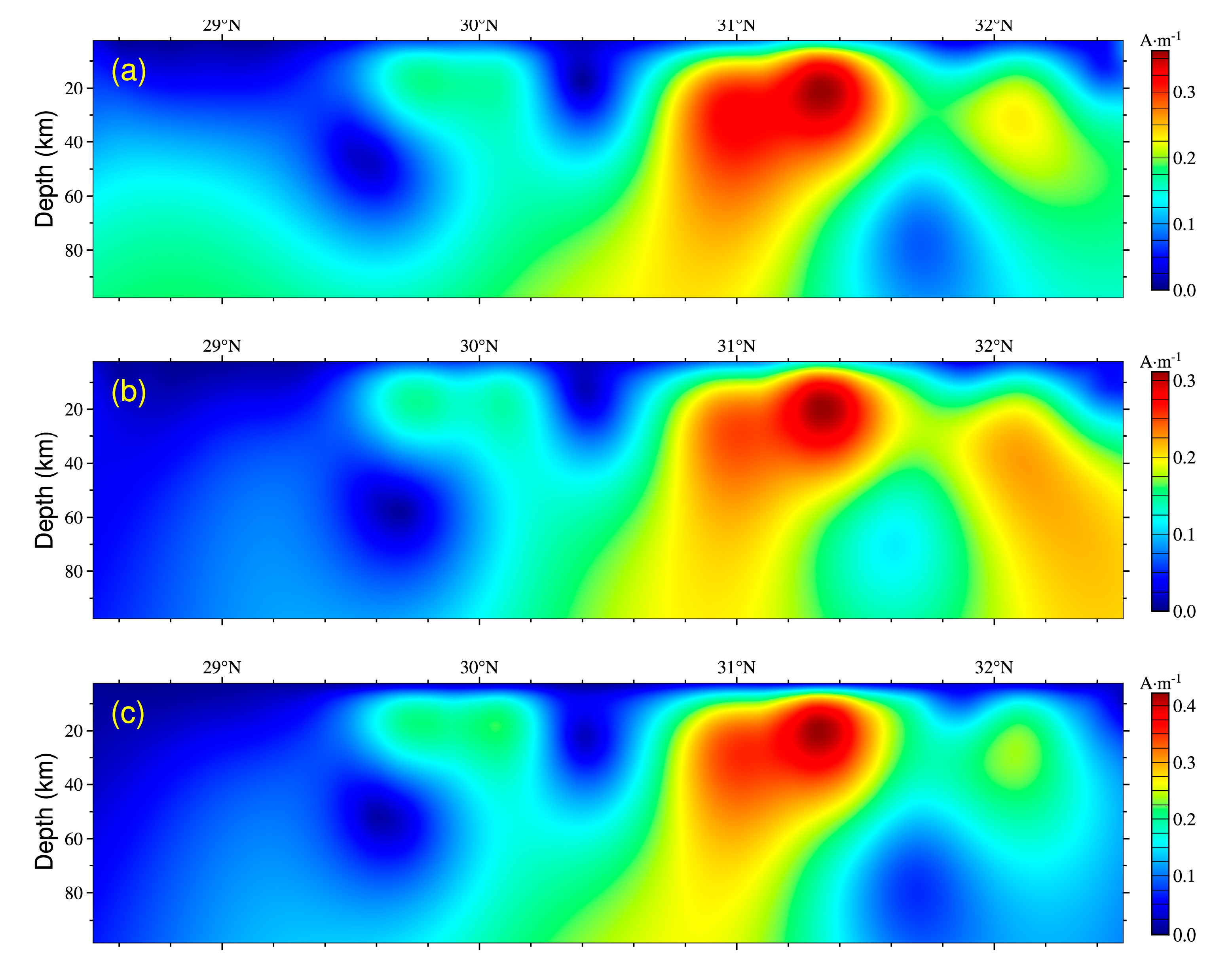
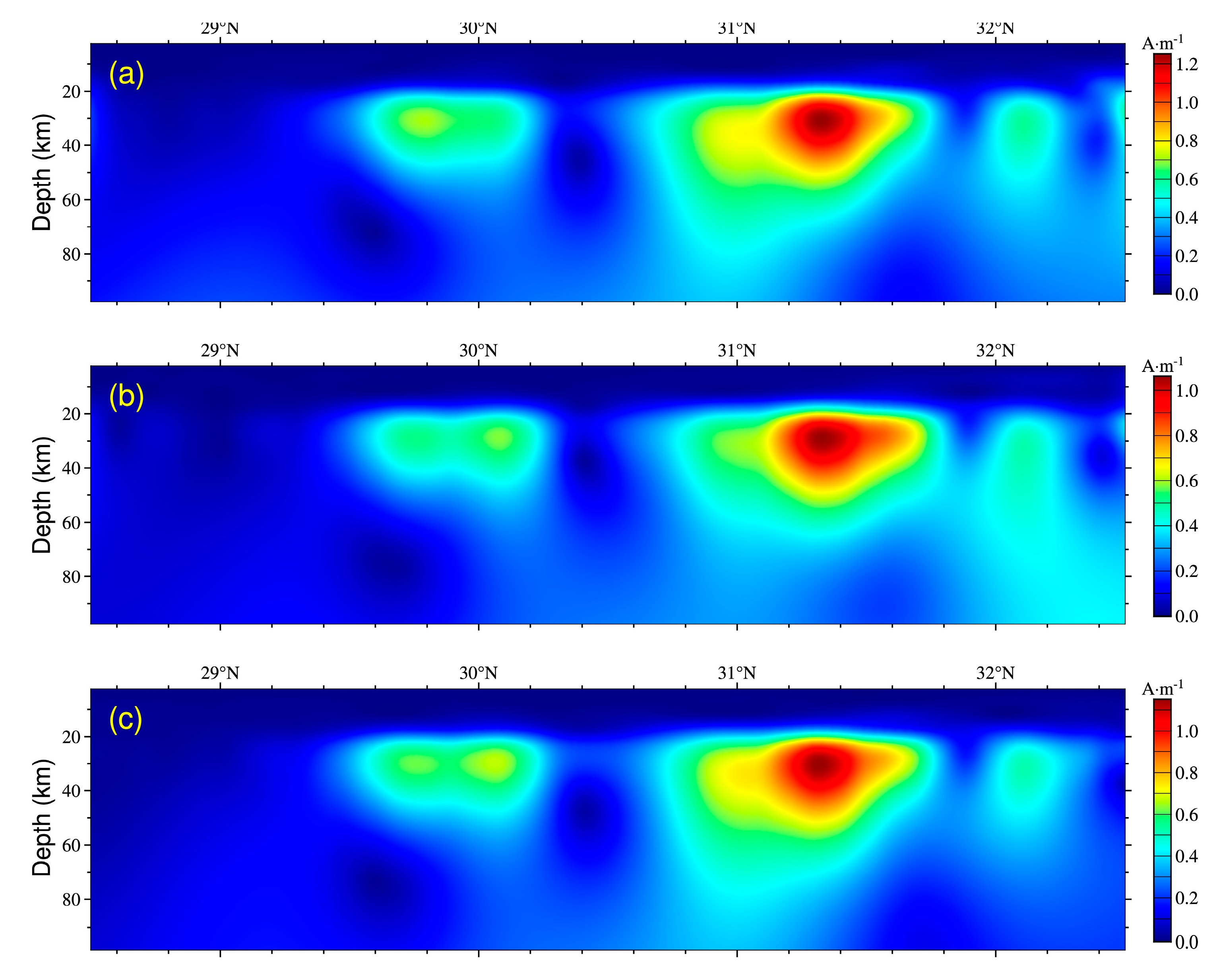
Figure 11 and Figure 12 show the vertical slices of the magnetization inversion results for the three-component magnetic anomalies of the Dabie orogen using Occam and the improved method, respectively.
There are three magnetic sources in the profile. However, the Occam method cannot determine the depth and extension of the magnetic field sources. In particular, the inversion results for Δ B x - and Δ B y - components data do not focus, even diverge on the boundary.
The improved method obtains a better inversion effect. We can clearly outline the contours of the three magnetic sources in Figure 12. The two magnetic sources below the surface near 30° N and 31° N, respectively, are consistent with the depth and horizontal extensions of the results of Yang and Li [58]. Comparing the inversion effects of the three-component magnetic data, it can be seen that the Δ B z - component is more stable.
The formation of UHP rocks indicates that the crustal rocks were subducted to depths of more than 100 km and then rapidly exhumed [61,62]. The upper part of the obvious magnetic source in Figure 12 is the F5 fault. Deep seismic wide-angle reflection/refraction studies have revealed that the Moho is cut off at 41 km below the F5 fault [63]. It may indicate the location of the magnetic source intrusions. The mafic-ultramafic intrusions exposed along the F5 included both alpine-type peridotite and pyroxene-gabbro intrusions produced by crust-mantle interactions. These are products of syn-collision intrusion processes [64], which may be related to the generation period of the magnetic source. At present, we know little about the information of magnetic structure, and we need to do further research in the future.
Figure 11. The inversion results for three-component magnetic anomalies of the Dabie orogen using the Occam method: (ac) the inversion results for Δ B x , Δ B y , and Δ B z , respectively.
Magnetochemistry 08 00157 g011
Figure 12. The inversion results for three-component magnetic anomalies of the Dabie orogen using the improved method: (ac) the inversion results for Δ B x , Δ B y , and Δ B z , respectively.
Magnetochemistry 08 00157 g012

5. Conclusions

We introduced the Occam inversion method into spherical coordinates and inverted the 3D magnetization intensity for the three-component magnetic anomalies. We designed two sets of synthetic models to test the inversion effects and noise impact. The results indicated that the Occam method could reflect the approximate position of the magnetic sources. At the same time, the boundary could not be delineated, and the resolution in the depth direction was low. Under the influence of noise, the inversion result of the Δ B z - component is relatively stable.
We proposed an improved inversion method and compared the imaging effects of the improved method and the Occam method on the two sets of synthetic models. The results showed that the developed method improved the focus and depth resolution.
The magnetization amplitudes of both algorithms deviated from the actual model, mainly caused by the volume effect of the spherical coordinates. We applied the improved method to the magnetic data of the Dabie orogen. The consistency of these results with those obtained from the continuous wavelet transform method verifies the newly developed algorithm.
Furthermore, to improve the computational efficiency, the observed grids or field source space cells of the forward modeling and inversion subdivision were still not sufficiently fine. It will be necessary to develop a fast algorithm suitable for larger regions or large-scale inversion in the future.

Author Contributions

L.Z.: conceptualization, investigation, and data processing and writing—original draft; S.C.: investigation, data processing, review and editing; G.L.: review and editing; Z.Z.: review and editing. All authors have read and agreed to the published version of the manuscript.

Funding

This work was supported by the National Natural Science Foundation of China (No. 41974148, 41704138). the Hunan Provincial Science & Technology Department of China (No. 2017JJ3069); the Hunan Provincial Key Laboratory of Share Gas Resource Exploitation (No. E21722); and the Project of Doctoral Foundation of Hunan University of Science and Technology (No. E51651).

Institutional Review Board Statement

Not applicable.

Informed Consent Statement

Not applicable.

Data Availability Statement

Not applicable.

Conflicts of Interest

All authors have no known competing financial interests or personal relationships that could have appeared to influence the work reported in this paper.

References

  1. Eppelbaum, L.; Katz, Y. A new regard on the tectonic map of the Arabian–African region inferred from the satellite gravity analysis. Acta Geophys. 2017, 65, 607–626. [Google Scholar] [CrossRef]
  2. Gao, G.; Kang, G.; Bai, C.; Li, G. Distribution of the crustal magnetic anomaly and geological structure in Xinjiang, China. J. Asian Earth Sci. 2013, 77, 12–20. [Google Scholar] [CrossRef]
  3. Nair, N.; Anand, S.P.; Rajaram, M.; Rao, P.R. A relook into the crustal architecture of Laxmi ridge, northeastern Arabian sea from geopotential data. J. Earth Syst. Sci. 2015, 124, 613–630. [Google Scholar] [CrossRef] [Green Version]
  4. Li, C.; Wang, J. Variations in Moho and Curie depths and heat flow in eastern and Southeastern Asia. Mar. Geophys. Res. 2016, 37, 1258. [Google Scholar] [CrossRef]
  5. Idárraga-García, J.; Vargas, C.A. Depth to the bottom of magnetic layer in South America and its relationship to Curie isotherm, Moho depth and seismicity behavior. J. Geod. Geodyn. 2018, 9, 93–107. [Google Scholar] [CrossRef]
  6. Wen, L.; Kang, G.; Bai, C.; Gao, G. Studies on the relationships of the curie surface with heat flow and crustal structures in Yunnan province, China, and its adjacent areas. Earth Planets Space 2019, 71, 85. [Google Scholar] [CrossRef] [Green Version]
  7. Lelièvre, P.G.; Oldenburg, D.W. A 3d total magnetization inversion applicable when significant, complicated remanence is present. Geophysics 2009, 74, L21–L30. [Google Scholar] [CrossRef]
  8. Du, J.; Chen, C.; Liang, Q.; Wang, H.; Li, Y.; Lane, R. 3-d inversion of regional magnetic data in spherical coordinates and its preliminary application in Australia. In Proceedings of the 23rd International Geophysical Conference and Exhibition, Melbourne, Australia, 11–14 August 2013. [Google Scholar]
  9. Liu, S.; Hu, X.; Zhang, H.; Geng, M.; Zuo, B. 3d magnetization vector inversion of magnetic data: Improving and comparing methods. Pure Appl. Geophys. 2017, 174, 4421–4444. [Google Scholar] [CrossRef]
  10. Liu, S.; Hu, X.; Zuo, B.; Zhang, H.; Geng, M.; Ou, Y.; Yang, T.; Vatankhah, S. Susceptibility and remanent magnetization inversion of magnetic data with a priori information of the köenigsberger ratio. Geophys. J. Int. 2020, 221, 1090–1109. [Google Scholar] [CrossRef]
  11. Wang, M.Y.; Di, Q.Y.; Xu, K.; Wang, R. Magnetization vector inversion equations and forword and inversed 2-d model study. Chin. J. Geophys. 2004, 47, 528–534. [Google Scholar] [CrossRef]
  12. Liu, S.; Hu, X.; Liu, T.; Feng, J.; Gao, W.; Qiu, L. Magnetization vector imaging for borehole magnetic data based on magnitude magnetic anomaly. Geophysics 2013, 78, D429–D444. [Google Scholar] [CrossRef]
  13. Li, Y.; Shearer, S.E.; Haney, M.M.; Dannemiller, N. Comprehensive approaches to 3d inversion of magnetic data affected by remanent magnetization. Geophysics 2010, 75, L1–L11. [Google Scholar] [CrossRef]
  14. Liu, S.; Hu, X.; Xi, Y.; Liu, T.; Xu, S. 2d sequential inversion of total magnitude and total magnetic anomaly data affected by remanent magnetization. Geophysics 2015, 80, K1–K12. [Google Scholar] [CrossRef]
  15. Liang, Q.; Chen, C.; Li, Y. 3-d inversion of gravity data in spherical coordinates with application to the grail data. J. Geophys. Res. Planets 2014, 119, 1359–1373. [Google Scholar] [CrossRef]
  16. Wang, H.; Li, Y.; Chen, C. 3d joint inversion of magnetic amplitude and gravity gradiometry data in spherical coordinates. In Proceedings of the SEG New Orleans Annual Meeting, New Orleans, LA, USA, 5–9 August 2015; SEG Technical Program Expanded Abstracts. pp. 1553–1557. [Google Scholar]
  17. Zhang, Y.; Wu, Y.; Yan, J.; Wang, H.; Rodriguez, J.A.P.; Qiu, Y. 3d inversion of full gravity gradient tensor data in spherical coordinate system using local north-oriented frame. Earth Planets Space 2018, 70, 58. [Google Scholar] [CrossRef]
  18. Zhao, G.; Chen, B.; Uieda, L.; Liu, J.; Kaban, M.K.; Chen, L.; Guo, R. Efficient 3-d large-scale forward modeling and inversion of gravitational fields in spherical coordinates with application to lunar mascons. J. Geophys. Res. Solid Earth 2019, 124, 4157–4173. [Google Scholar] [CrossRef] [Green Version]
  19. Li, Y.G.; Oldenburg, D.W. 3-d inversion of magnetic data. Geophysics 1996, 61, 394–408. [Google Scholar] [CrossRef]
  20. Li, Y.; Oldenburg, D.W. Separation of regional and residual magnetic field data. Geophysics 1998, 63, 431–439. [Google Scholar] [CrossRef]
  21. Portniaguine, O.; Zhdanov, M.S. Focusing geophysical inversion images. Geophysics 1999, 64, 874–887. [Google Scholar] [CrossRef] [Green Version]
  22. Zhdanov, M.S.; Ellis, R.; Mukherjee, S. Three-dimensional regularized focusing inversion of gravity gradient tensor component data. Geophysics 2004, 69, 925–937. [Google Scholar] [CrossRef]
  23. Asli, M.; Marcotte, D.; Chouteau, M. Direct inversion of gravity data by cokriging. In Geostat2000, Proceedings of the International Geostatistics Congress, Rio de Janeiro, Brazil, 6–17 August 2000; Springer: Cape Town, South Africa, 2000. [Google Scholar]
  24. Geng Meixia, G.M.; Huang Danian, H.D.; Yang Qingjie, Y.Q.; Liu Yinping, L.Y. 3d inversion of airborne gravity-gradiometry data using cokriging. Geophysics 2014, 79, G37–G47. [Google Scholar] [CrossRef]
  25. Krahenbuhl, R.A.; Li, Y. Inversion of gravity data using a binary formulation. Geophys. J. Int. 2006, 167, 543–556. [Google Scholar] [CrossRef] [Green Version]
  26. Zhdanov, M.S.; Cox, L.H. Multinary inversion for tunnel detection. IEEE Geosci. Remote Sens. Lett. 2013, 10, 1100–1103. [Google Scholar] [CrossRef]
  27. Sun, J.; Li, Y. Multidomain petrophysically constrained inversion and geology differentiation using guided fuzzy c-means clustering. Geophysics 2015, 80, D1–D18. [Google Scholar] [CrossRef]
  28. Constable, S.C.; Parker, R.L.; Constable, C.G. Occam’s inversion; A practical algorithm for generating smooth models from electromagnetic sounding data. Geophysics 1987, 52, 289–300. [Google Scholar] [CrossRef]
  29. Tikhonov, A.N.; Arsenin, V.Y. Solutions of Ill-Posed Problems; American Mathematical Society: Ann Arbor, MI, USA, 1977. [Google Scholar]
  30. Moghadas, D.; Engels, M.; Schwalenberg, K. 1d joint multi-offset inversion of time-domain marine controlled source electromagnetic data. Geophys. Prospect. 2015, 63, 1334–1354. [Google Scholar] [CrossRef]
  31. Tian, Y.; Wang, Y. Inversion of the density structure of the lithosphere in the north China craton from goce satellite gravity gradient data. Earth Planets Space 2018, 70, 173. [Google Scholar] [CrossRef]
  32. Lesur, V.; Gubbins, D. Using geomagnetic secular variation to separate remanent and induced sources of the crustal magnetic field. Geophys. J. Int. 2000, 142, 889–897. [Google Scholar] [CrossRef] [Green Version]
  33. Hulot, G.; Olsen, N.; Thébault, E.; Hemant, K. Crustal concealing of small-scale core-field secular variation. Geophys. J. Int. 2009, 177, 361–366. [Google Scholar] [CrossRef] [Green Version]
  34. Hemant, K.; Maus, S. Why no anomaly is visible over most of the continent–ocean boundary in the global crustal magnetic field. Phys. Earth Planet. Inter. 2005, 149, 321–333. [Google Scholar] [CrossRef]
  35. Hemant, K.; Mitchell, A. Magnetic field modelling and interpretation of the Himalayan–Tibetan plateau and adjoining north indian plains. Tectonophysics 2009, 478, 87–99. [Google Scholar] [CrossRef]
  36. Gao, G.; Kang, G.; Li, G.; Bai, C. Crustal magnetic anomaly in the ordos region and its tectonic implications. J. Asian Earth Sci. 2015, 109, 63–73. [Google Scholar] [CrossRef]
  37. Vonfrese, R.R.B.; Hinze, W.; Braile, L.; Luca, A. Spherical-earth gravity and magnetic anomaly modeling by gauss-legendre quadrature integration. J. Geophys. Z. Geophys. 1981, 49, 234–242. [Google Scholar]
  38. Asgharzadeh, M.F.; von Frese, R.R.B.; Kim, H.R. Spherical prism magnetic effects by gauss-legendre quadrature integration. Geophys. J. Int. 2008, 173, 315–333. [Google Scholar] [CrossRef] [Green Version]
  39. Du, J.; Chen, C.; Lesur, V.; Lane, R.; Wang, H. Magnetic potential, vector and gradient tensor fields of a tesseroid in a geocentric spherical coordinate system. Geophys. J. Int. 2015, 201, 1977–2007. [Google Scholar] [CrossRef] [Green Version]
  40. Blakely, R.J. Potential Theory in Gravity and Magnetic Applications, 1st ed.; Cambridge University Press: New York, NY, USA, 1995; pp. 91–93. [Google Scholar]
  41. Heiskanen, W.A.; Moritz, H. Physical Geodesy; W.H. Freeman and Company: San Francisco, CA, USA; London, UK, 1967; pp. 46–48. [Google Scholar]
  42. Ku, C.C. A direct computation of gravity and magnetic anomalies caused by 2- and 3-dimensional bodies of arbitrary shape and arbitrary magnetic polarization by equivalent-point method and a simplified cubic spline. Geophysics 1977, 42, 610–622. [Google Scholar] [CrossRef]
  43. Asgharzadeh, M.F.; von Frese, R.R.B.; Kim, H.R.; Leftwich, T.E.; Kim, J.W. Spherical prism gravity effects by gauss-legendre quadrature integration. Geophys. J. Int. 2007, 169, 1–11. [Google Scholar] [CrossRef] [Green Version]
  44. Heck, B.; Seitz, K. A comparison of the tesseroid, prism and point-mass approaches for mass reductions in gravity field modelling. J. Geodesy 2007, 81, 121–136. [Google Scholar] [CrossRef]
  45. Uieda, L.; Barbosa, V.C.F.; Braitenberg, C. Tesseroids: Forward-modeling gravitational fields in spherical coordinates. Geophysics 2016, 81, F41–F48. [Google Scholar] [CrossRef]
  46. Li, Y.G. 3-d inversion of gravity gradiometer data. In Proceedings of the Paper Presented at the 2001 SEG Annual Meeting, San Antonio, TX, USA, 9–14 September 2001. [Google Scholar]
  47. Joulidehsar, F.; Moradzadeh, A.; Doulati Ardejani, F. An improved 3d joint inversion method of potential field data using cross-gradient constraint and lsqr method. Pure Appl. Geophys. 2018, 175, 4389–4409. [Google Scholar] [CrossRef]
  48. Pilkington, M. 3-d magnetic imaging using conjugate gradients. Geophysics 1997, 62, 1132–1142. [Google Scholar] [CrossRef]
  49. Li, Y.; Yang, Y. Gravity data inversion for the lithospheric density structure beneath north China craton from egm 2008 model. Phys. Earth Planet. Inter. 2011, 189, 9–26. [Google Scholar] [CrossRef]
  50. Chen, S.H.; Zhu, Z.Q.; Lu, G.Y.; Cao, S.J. Inversion of gravity gradient tensor based on preconditioned conjugate gradient. J. Cent. South Univ. (Sci. Technol.) 2013, 44, 619–625, (In Chinese with English abstract). [Google Scholar]
  51. Last, B.J.; Kubik, K. Compact gravity inversion. Geophysics 1983, 48, 713–721. [Google Scholar] [CrossRef]
  52. Guillen, A.; Menichetti, V. Gravity and magnetic inversion with minimization of a specific functional. Geophysics 1984, 49, 1354–1360. [Google Scholar] [CrossRef]
  53. Silva, J.B.C.; Medeiros, W.E.; Barbosa, V.C.F. Gravity inversion using convexity constraint. Geophysics 2000, 65, 102–112. [Google Scholar] [CrossRef]
  54. Ames, L.; Tilton, G.R.; Zhou Gaozhi, Z.G. Timing of collision of the Sino-Korean and Yangtse cratons; U-pb zircon dating of coesite-bearing eclogites. Geology 1993, 21, 339–342. [Google Scholar] [CrossRef]
  55. Hacker, B.R.; Ratschbacher, L.; Liou, J.G. Subduction, collision and exhumation in the ultrahigh-pressure Qinling-Dabie orogen. Geol. Soc. Lond. Spec. Publ. 2004, 226, 157–175. [Google Scholar] [CrossRef] [Green Version]
  56. Zhang, H.; Gao, S.; Zhong, Z.; Zhang, B.; Zhang, L.; Hu, S. Geochemical and sr–nd–pb isotopic compositions of cretaceous granitoids: Constraints on tectonic framework and crustal structure of the Dabieshan ultrahigh-pressure metamorphic belt, China. Chem. Geol. 2002, 186, 281–299. [Google Scholar] [CrossRef]
  57. Wang, C.; Zeng, R.; Mooney, W.D.; Hacker, B.R. A crustal model of the ultrahigh-pressure Dabie Shan orogenic belt, China, derived from deep seismic refraction profiling. J. Geophys. Res. Solid Earth 2000, 105, 10857–10869. [Google Scholar] [CrossRef] [Green Version]
  58. Yang, Y.; Li, Y. Crustal structure of the Dabie orogenic belt (eastern China) inferred from gravity and magnetic data. Tectonophysics 2018, 723, 190–200. [Google Scholar] [CrossRef]
  59. Xu, Y.X.; Zhang, S.; Griffin, W.L.; Yang, Y.J.; Yang, B.; Luo, Y.H.; Zhu, L.P.; Afonso, J.C.; Lei, B.H. How did the Dabie orogen collapse? Insights from 3-d magnetotelluric imaging of profile data. J. Geophys. Res. Solid Earth 2016, 121, 5169–5185. [Google Scholar] [CrossRef]
  60. Purucker, M.E.; Whaler, K.A. Crustal magnetism. Treatise Geophys. 2007, 5, 195–235. [Google Scholar]
  61. Shutong, X.; Wen, S.; Yican, L.; Laili, J.; Shouyuan, J.; Okay, A.I.; Sengor, A.M.C. Diamond from the Dabie Shan metamorphic rocks and its implication for tectonic setting. Science 1992, 256, 80–82. [Google Scholar] [CrossRef]
  62. Chopin, C. Ultrahigh-pressure metamorphism: Tracing continental crust into the mantle. Earth Planet. Sci. Lett. 2003, 212, 1–14. [Google Scholar] [CrossRef]
  63. Faure, M.; Lin, W.; Schärer, U.; Shu, L.; Sun, Y.; Arnaud, N. Continental subduction and exhumation of uhp rocks. Structural and geochronological insights from the Dabieshan (east China). Lithos 2003, 70, 213–241. [Google Scholar] [CrossRef]
  64. Wang, J.; Deng, S. Emplacement age for the mafic-ultramafic plutons in the northern Dabie Mts. (Hubei): Zircon U-Pb, Sm-Nd and 40Ar/39Ar dating. Sci. China Ser. D Earth Sci. 2002, 45, 1. [Google Scholar] [CrossRef]
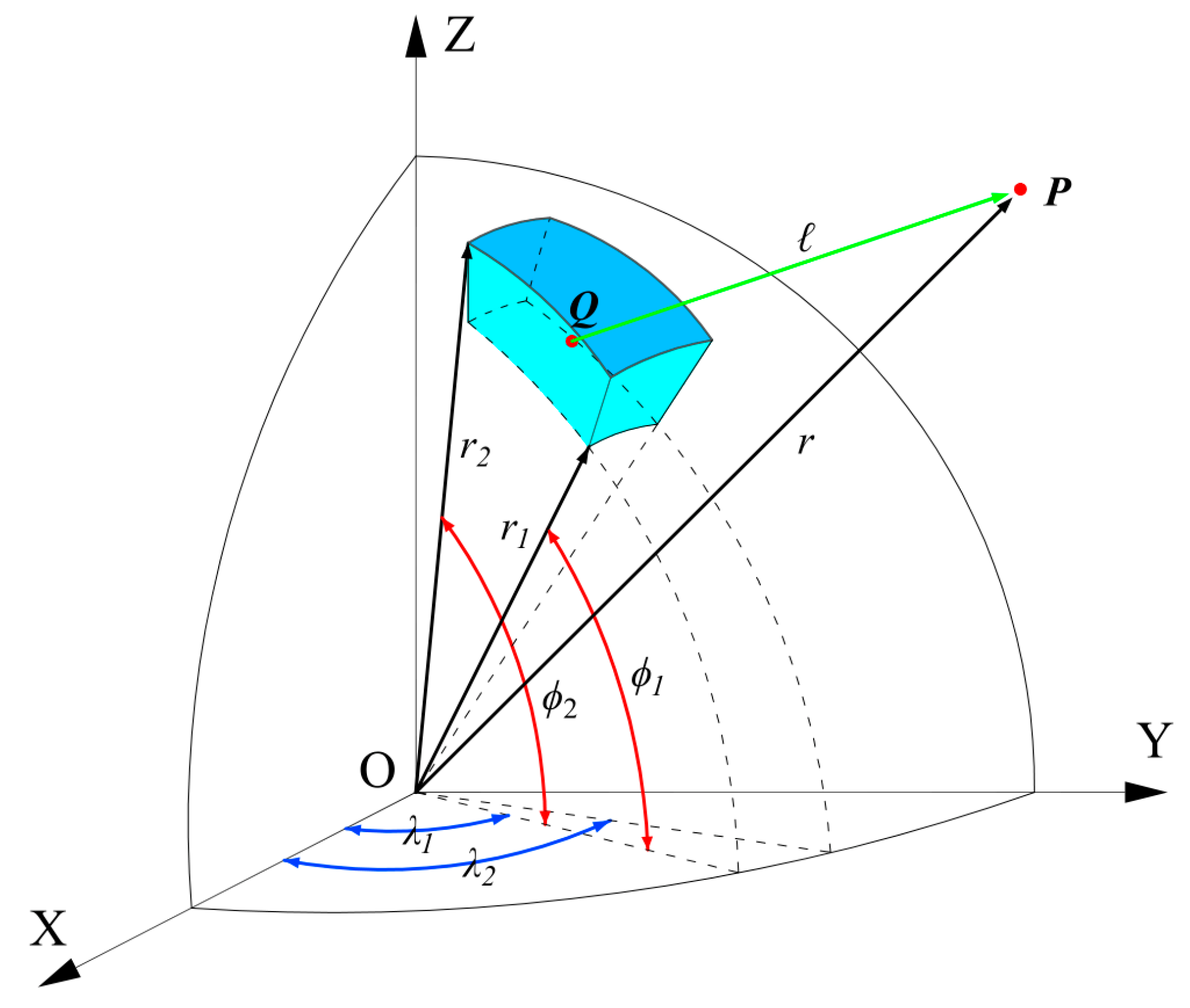
Figure 1. Geometry of the tesseroid.
Magnetochemistry 08 00157 g001
Figure 2. 3D visualization of models: (a) the first set of models; (b) the second set of models.
Magnetochemistry 08 00157 g002
Figure 6. Three-component magnetic anomalies, Δ B x , Δ B y , and Δ B z , of the second set of models: (ac) cases with noise-free; (df) cases with 5% noise signal.
Magnetochemistry 08 00157 g006
Figure 7. The inversion results for three-component magnetic anomalies using the Occam method: (af) are the profiles at latitude = 29.8°, where (ac) are the inversion results for Δ B x , Δ B y , and Δ B z of noise-free, (df) are the inversion results for Δ B x , Δ B y , and Δ B z with 5% noise signal; (gl) are the profiles at longitude = 114.5°, where (gi) are the inversion results for Δ B x , Δ B y , and Δ B z of noise-free, (jl) are the inversion results for Δ B x , Δ B y , and Δ B z with 5% noise signal.
Magnetochemistry 08 00157 g007
Figure 8. The inversion results for three-component magnetic anomalies using the improved method: (af) are the profiles at latitude = 29.8°, where (ac) are the inversion results for Δ B x , Δ B y , and Δ B z of noise-free, (df) are the inversion results for Δ B x , Δ B y , and Δ B z with 5% noise signal; (gl) are the profiles at longitude = 114.5°, where (gi) are the inversion results for Δ B x , Δ B y , and Δ B z of noise-free, (jl) are the inversion results for Δ B x , Δ B y , and Δ B z with 5% noise signal.
Magnetochemistry 08 00157 g008
Figure 9. Simplified geological map of the Dabie orogen (modified from Zhang et al. [56]). Note: In the figure, F1 is the Xinyang-Shucheng fault zone; F2 is the Xiangfan-Guangji fault zone; F3 is the Dawu fault; F4 is the Tancheng-Lujiang fault zone; F5 is the Tongbai-Shangcheng-Mozitan-Xiaotian fault zone; F6 is the Shangcheng-Macheng-Tuancheng fault zone; F7 is the Wuhe-Shuihou fault zone.
Magnetochemistry 08 00157 g009
Figure 10. Lithospheric three-component magnetic anomalies of the Dabie orogen at an altitude of 4 km: (ac) Δ B x , Δ B y , and Δ B z , respectively. Note: A - A represents the profile line position.
Magnetochemistry 08 00157 g010
Table 1. Synthesis models’ geometry and magnetic parameters.
Model IdLongitudeLatitudeDepthInclinationDeclination
A114.0–115.030.1–30.930–1004545
B116.0–117.030.1–30.930–1004545
C114.2–114.831.2–31.830–704545
D116.0–117.031.3–31.740–1006045
E114.1–114.929.5–30.340–904560
F116.3–116.729.3–30.330–709030
Note: In the table, the units of longitude, latitude, inclination, and declination are shown in degrees; the units of depth are in km.
Publisher’s Note: MDPI stays neutral with regard to jurisdictional claims in published maps and institutional affiliations.