Abstract
Electroporation is a technique applied both in biomedical and biotechnological fields which uses a high-voltage electric current to temporarily destabilize the plasma membrane of living cells, permitting the introduction of small molecules as well as nucleic acids into the cytosol. Besides viral and chemical transfections, this method is a common way to manipulate living cells. However, the majority of electroporation machines available on the market can only work using batch-based cuvettes treating only a few micrograms of cells. To transform cells in the order of several grams in the quickest possible way, it is necessary to use a continuous-flow method. In this work, we present the design, electric and fluid dynamics simulations, construction and testing of a flow cuvette that can adapt to standard electroporator systems. The flow cuvette connected with a peristaltic pump was able to successfully electroporate 20 mL of medium containing microalgae cells in less than 5 min. Microalgae Scenedesmus almeriensis cells were transfected with a fluorescent siRNA oligo as well as magnetically transformed by introducing magnetic nanoparticles in their cytoplasm. The flow cuvette presented here offers a valid tool for the high-throughput transformation/transfection/transfer of both prokaryotic and eukaryotic organisms, especially suitable for bioreactor cultivation and other industrial biotechnological contexts.
1. Introduction
The incorporation of genetic material in the cell cytoplasm can be achieved with various methods. Viral transfection is quite efficient; however, it can provoke mutagenesis, it is an expensive method and the genetic load that can be transferred is limited [1,2,3]. To promote temporary pores on the cells’ membrane, several other methods are used such as sonoporation [4,5], which uses ultrasound, mechanoporation [6,7], which uses shear stresses, heat shock [8], which uses rapid temperature changes and electroporation [9], which uses electric fields. Other methods to transfect nucleic acids into eukaryotic cells are the calcium phosphate [10] and the lipid-based techniques [11]. Some of the above-mentioned methods can also be used to introduce nongenetic material into the cytosol of living cells.
Electroporation is a common biotechnological technique, established in the 1990s and used for the introduction of molecules in the cytoplasm of cells [12,13]. Such molecules can be oligo and plasmid DNA, interference RNA or small compounds. Due to the method’s characteristics, electroporation works on batches and not as a continuous method, thus limiting the productivity of the transfection. The commercial cuvettes used for electroporation have a capacity ranging between 300 and 500 μL which is about 4 × 10⁵ cells per batch. This productivity rate is undesirable for industrial application such as antibody production or molecular therapy where a much higher rate is demanded [7,14,15].
The transmembrane potential induced by an external electric field (ΔψE) at a specific site on the cell membrane can be expressed using the following equation:
where the cell is assumed to be a sphere of radius r; g(λ) is a complex function of the conductivities of the membrane, the cytoplasm and the surrounding buffer; E is the external electric field intensity; and θ is the angle between the direction of the electric field and the normal to the membrane at a specific site of the cell [16].
When the transmembrane potential of the cell is increased to a critical threshold point (0.2–1 V), pores are formed on the membrane which can spontaneously reseal after the electric field is removed [16]. The required optimal electric field depends on the buffer and membrane conductivity, cell size and the strength and distribution of the external electric field [17,18].
Many attempts have been made to upscale the process by utilizing devices that enable continuous operation. Microfluidic devices have been tested with quite accurate results due to the size of the device and decreased nonuniformities in the produced field [17,19]. However, the small size of these devices is limiting for many applications. Other devices with plate electrodes have also been tested but they have been proven unreliable due to the big distance of the plates leading to the necessity of high voltages that are difficult to control and usually damage the cells to be transfected.
The device presented herein is designed to fit in the commercial Bio-Rad MicroPulser Electroporator in order to ensure a wide compatibility with electric field generators, the viability of the cells and the uniformity of the field generated. The device is a “sandwich” comprised of two aluminium plates and a comb-like structure creating a channel where the fluid passes through. The plates are connected at the Bio-Rad MicroPulser electrodes and a peristaltic pump is used to drive the cell solution through the flow cuvette. To test the efficacy of the device to temporarily destabilize the cell membrane, we used as cell model the microalga Scenedesmus almeriensis (S. almeriensis) and as foreign material iron oxide nanoparticles with an average size of 100 nm as well as fluorescent small interference RNA (siRNA) oligos.
The device described is constructed with low-cost materials, is easy to manufacture, can be easily sterilized and, if necessary, used multiple times after cleaning.
2. Materials and Methods
2.1. Cultivation of S. almeriensis and Pre-treatment
S. almeriensis cells were generously provided by Dr. Antonio Molino. Cells from a preculture, in the exponential phase, were inoculated into 1000 mL Erlenmeyer flask containing 600 mL of Mann and Myers medium and harvested when the concentration of microalgae was roughly 1 g/L. The culture conditions were the following: light intensity of 60–80 μE/m2/s, temperature of 20 °C with gentle agitation. For electroporation experiments, 100 mL (~100 mg) of culture was harvested by centrifugation at 2000× g for 10 min at 4 °C and washed three times with 1 mL 0.6 M 14 sorbitol/mannitol buffer, then pretreated (cell wall removal) and resuspended in 20 mL 0.6 M sorbitol/mannitol buffer. Cell wall removal (protoplast preparation) was performed using a single-enzyme treatment as reported previously in Savvidou et al. [20,21]. Briefly, the cell pellet was suspended in 25 mM phosphate buffer (pH 7.0) containing 0.6 M D-mannitol/mannitol and the polysaccharide-degrading enzyme cellulase (2%). The incubation temperature was chosen based on the literature as well as our preliminary data as 30 °C for 16 h (overnight). The digestion was performed in a final volume of 10 mL. After digestion, the enzymes and digestion debris were removed by 2 washing steps and the cells were resuspended in 5 mL of medium for electroporation. All solutions used for digesting, washing and electroporation contained 0.6 M D-mannitol to equilibrate the osmotic pressure.
2.2. siRNA Transfection and Analysis
A quantity of 20 mL of pretreated microalgae cells was mixed with an FITC-Conjugate siRNA oligo (Santa Cruz Biotechnology, sc-36869, Heidelberg, Germany) at a final concentration of 100 nM and incubated at room temperature for 20 min before electroporation. Control siRNA is a scrambled nonspecific 19–25 nt siRNA designed to measure transfection efficiency. Using a peristaltic pump (DuLabo PLP380, Labortechnik, Wasserburg, Germany) with an 8-cylinder rolling head (PHP5062, Labortechnik, Wasserburg, Germany) and a 3 mm hose, the mixture was pumped inside the flow cuvette at a rate of 100 μL/second. The pulse generator (MicroPulser, Bio-Rad, Hercules, CA, USA) was manually set at 3 KV [22]. The average pulse duration was between 3 and 5 milliseconds. The mixture of microalgae and siRNA oligo after electroporation was pumped in a clean tube and incubated for 24 h before observation.
The presence of siRNA inside the microalgae cells was detected using fluorescent microscopy with appropriate filters. Hoechst 33258 (Santa Cruz Biotechnology, sc-394039, Heidelberg, Germany) was mixed with cells at a final concentration of 10 μM for 30 min and then washed prior to microscope observation in order to counterstain nuclei and other subcellular structures containing DNA. A total of 20 μL of microalgae cells was dried on a glass slide and a drop of mounting solution (Fluoromount, Merck, F4680-25, Darmstadt, Germany) was used alongside a coverslip. Fluorescence microscopy studies were performed using the epifluorescent upright microscope Olympus BX-50 (Olympus Optical Co., GmbH, Hamburg, Germany). Excitation was achieved using a 100 W mercury arc lamp and brightfield and fluorescence images were acquired by a colour CCD camera (XC-30; Olympus, Hamburg, Germany). The Hoechst stain was excited by ultraviolet light at 350 nm with an emission maximum at 461 nm (blue/cyan fluorescence light), whereas the FITC-Conjugate siRNA oligo was excited at 490 nm and the emission maximum was at 514 nm (green fluorescence light).
2.3. Nanoparticles Transfer and Analysis
Experimental investigations were carried out by using ferrofluid nanoparticles (fluidMAG-lipid from Chemicell, Germany) consisting of an aqueous dispersion of magnetic iron oxides (magnetite) with a diameter of 80–100 nm and covered with phosphatidylcholine. Phosphatidylcholine forms, over the iron oxides core, a coating layer similar to a cell membrane. This characteristic gives an excellent biocompatibility since coated nanoparticles do not cross-react with the molecules and organelles of the cytosol. Nanoparticles at a final concentration of 50 ng/mL were added to 20 mL of pre-treated cells and incubated at room temperature for 20 min, then electroporated using the same protocol described for the siRNA assay. The presence of nanoparticles was detected with Prussian blue staining and transmission light microscope observation after 48 h. The suspension of electroporated cells (20 mL) was transferred in a glass flask with 480 mL of fresh medium in order to dilute the culture and incubated for 48 h. Before observation, the cells were washed to remove any excess of noninternalized magnetic particles.
2.4. Viability of Cells after Electroporation
After electroporation, cells deprived of their natural cell wall cannot survive if they are directly cultivated in normal media because of osmotic issues and of the fragility of their body. The efficiency of cell wall reconstitution and regeneration after protoplast preparation was studied in our previous works [20,21]. Based on our previous results, after electroporation, we cultivated S. almeriensis protoplast in a medium containing 2% glucose for 8 days. Every 2 days, we measure the optical density of the culture at 600 nm and used these values to construct growth curves. If cells were permanently damaged by the electroporation with the flow cuvette and not able to perform photosynthesis, the culture optical density would decrease day by day; on the contrary, an increase in culture optical density would indicate low or no cell death.
In order to compare the performance of the flow cuvette with standard cuvettes, we generated in parallel five growth curves: cells not electroporated, cells electroporated with the flow cuvette with and without glucose in the medium and cells electroporated with a standard 2 mm Bio-Rad cuvette with and without glucose in the medium.
2.5. Prussian Blue Staining
A Prussian blue reagent pack was purchased from BioPAL (Biopal, Worcester, MA, USA). The reagent pack consisted of reagent A (4% Prussian blue K4Fe(CN)6 in water), reagent B (4% HCL) (Biopal, Worcester, MA, USA) and phosphate buffered saline (PBS) (Gibco/Life Technologies Ltd., Paisley, UK). Briefly, cells were fixed in methanol/acetone for 10 min at −20 °C, a sufficient amount of Prussian blue cell-staining reagent was prepared by mixing equal amounts of reagent A with reagent B. Fixed cells and cell-staining reagents were mixed and left for 60 min at room temperature. During this time, if iron was present, a blue colour would develop that could be observed with a microscope.
2.6. Three-Dimensional Printing
The plastic part of the electroporator flow cuvettes was printed with a Flashforge Creator Pro using a nozzle of 0.4 mm diameter. The speed of the printer was set to 50 mm/s and the layer thickness was 0.2 mm with a print precision of ±0.2 mm. An external spool was used with a filament diameter of 1.75 mm.
Acrylonitrile butadiene styrene (ABS) was used for 3D printing. The material is compliant with the ISO 10993 and USP class VI biocompatibility standards. The material has been included in Drug Master Files (DMF) for use in medical and food contact applications in both Europe and the USA. Furthermore, ABS along with polycarbonate are the most commonly used plastics for electrical applications. Its dielectric strength is 18–50 kV/mm making it a safe choice as the electroporation device insulator.
The flow cuvette was designed using Solidworks software (licensed to NTUA) and the file was transferred to FlashPrint software which converted the file to one compatible with the printer.
3. Results and Discussion
3.1. Flow Cuvette Design, Fluid Dynamics and Electrical Field Simulations
To develop a continuous uptake system, we first optimized S. almeriensis transformation with different quantities of cells as well as nanoparticles and siRNA using standard cuvettes and electroporator machines. It is worth noting that the limiting part for a continuous-flow electroporation in this system was the design of the standard cuvettes that can fit only a few hundred microliters (100–400 μL) of medium.
The standard cuvette was fabricated using conductive metal (aluminium) and plastic, embedded together to form a small tank with a square shape. The distance between metallic walls could vary as well as the volume of the solution to be electroporated. A solution containing the cells that needed to be electroporated was added, as well as removed, inside the cuvettes by using micropipettes.
We reasoned that to obtain a continuous-flow electroporation it was necessary to modify only the design of the standard cuvettes as the commercial pulse generator can guarantee the production of appropriate electrostatic fields. Many modifications were analysed. After the computer simulations, one design was chosen. The basic design, as seen in Figure 1a, consisted of two aluminium plates and a plastic comb-like dielectric forming a chamber, that worked similarly to a capacitor, through which the fluid flowed.
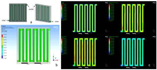
Figure 1.
(a) Continuous-flow electroporation chamber with square turns; (b) electric field intensity distribution in the chamber; (c) fluid flow characteristics inside the chamber with rectangular turns.
The dimensions of the internal channel (green part) were 2 mm wide and 2 mm thick, and so were the dimensions of the combs (grey part), allowing a volume of V = 14.56 × 10⁻⁶ m3 (14.56 mL) to receive the electric pulse.
For each cell entering the device (inlet side), we assumed that it needed n seconds to flow through the channel till the outlet. With this assumption, it was possible to adjust the electric pulse(s) frequency at 1/n in order to provide one pulse per cell, if necessary. However, if more than one pulse was necessary, the frequency of the pulse could be adjusted with respect to the time a given cell spent inside the chamber. By pumping medium inside the chamber at a given rate, the process became continuous.
The electric field produced by the electrodes is given:
where E is the electric field intensity; V is the voltage; d is the distance between the electrodes (2 mm).
The capacitor discharge is governed by the equation given:
where Vo is the initial (peak) voltage; τ = RxC is the time constant; R is the resistance of the circuit expressed in ohms; C is the capacitance of the apparatus expressed in microfarads.
Regarding the homogeneity of the electric pulse provided by this structure, simulations in ANSYS (licensed to NTUA) were carried out. As seen in Figure 1b, the electric field intensity appeared to be homogeneous in most of the parts (green areas) and through all the chamber volume.
Furthermore, simulations in ANSYS Fluent were carried out in order to study the fluid dynamics of medium containing cells into the channel. A realizable k-epsilon model with standard wall functions was chosen for the analysis, and the geometry was meshed with ~10,000 nodes. It was observed (Figure 1c) that turbulences were created at the corners, suggesting that cells could be trapped in these areas and spend more time than expected in the cuvette.
To overcome the above-mentioned difficulty, the design of the inner channel was modified. Indeed, we opted for smooth turns (Figure 2a) instead of 90° corners.
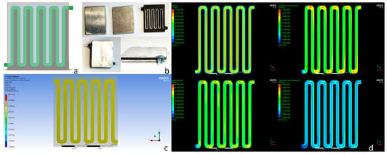
Figure 2.
(a) Electroporation chamber with smoothed corners. (b) Channels’ chamber system that was used to fabricate the continuous electroporation apparatus. Metallic plates were glued to the two plastic structures. (c) Electric field intensity distributed in the chamber. (d) Fluid flow characteristics inside the chamber with smooth turns.
Using the same inlet velocity of the previous simulations (Figure 1c), the fluid flow was smoother as can be seen in Figure 2d. The turbulence kinetic energy was distributed more homogeneously and thus, cells did not stall at the turns of the device.
Summarizing, after fluid and electric simulations, the optimum apparatus consisted of a plastic comb-like structure with smoothened corners forming the flow channel and metallic plates playing the role of the electrodes.
3.2. Flow Cuvette Construction
To realize the device, a plastic structure from ABS forming the above-mentioned chamber was 3D-printed and two aluminium plates were glued on both sides to form the electroporation chamber. Two silicon tubes with a diameter of 1 mm were attached to the inlet and outlet of the chamber in order to transfer the solution to be electroporated (Figure 1c). The complete apparatus is depicted in Figure 3.
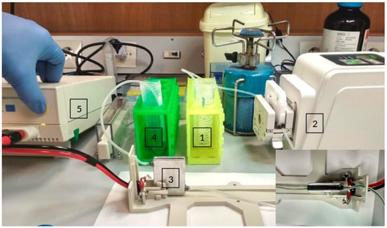
Figure 3.
Microalgae cells and the magnetic nanoparticles are contained in the testing tube (1). From there, the peristaltic pump (2) pulls the mixture and drives it through the electroporator device (3). Then, the mixture ends up in collector tube (4). The electric generator is controlled manually (5). On the right bottom corner is a top view of the electroporator device at the base of the Bio-Rad electroporator.
The last step to complete the continuous flow electroporator was to adjust the Bio-Rad MicroPulser in such a way as to provide the pulses continuously. To achieve this, an ATmega2560 microcontroller and a relay were connected to the circuit of the electroporator’s switch. By programming the microcontroller, the pulses could be generated at the necessary time intervals.
3.3. Testing Flow Cuvettes
Two different materials were transfected into the cytoplasm of S. almeriensis. The first material was magnetic nanoparticles, whereas the second material was a fluorescent siRNA oligo. S. almeriensis microalga strain was selected since the transfection experiments did not need any particular sterile conditions, cells were sufficiently big (~10 µm) and the challenge represented by the presence of the cell wall signified a strong barrier to transfection. On average, we could estimate that each cell received only one electric pulse when transiting inside the flow cuvette. To verify the effects of such a pulse on cell viability and compare such effects with those observed with a standard batch-based cuvette, we determined the growth curves of cells electroporated with both types of cuvettes. Furthermore, in parallel with the electroporated cells, we also evaluated the growth curves of nonelectroporated cells. The growth curves of the cells transfected with magnetic nanoparticles are shown in Figure 4. According to our previous works [20,21], after electroporation, it is necessary to supplement the microalgae growth medium with 2% glucose in order to keep cells alive since they cannot sustain the double stress coming from the cell wall removal and from electroporation. In Figure 4, we can see that cells electroporated with both systems (dark blue and orange curves) grew with comparable rates only if they were supplemented with 2% glucose. If electroporated cells were not supplanted, independently by the cuvette used, the entire cultures died after a few days (yellow and grey curves). Therefore, independently of the cuvette we used, the cells’ viability strongly depended on the recovery medium used [20,21].
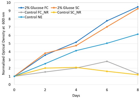
Figure 4.
Growth curves comparison between cells electroporated with standard (SC) and flow-cuvette (FC) systems. Only magnetic nanoparticles were used in this experiment. Three control experiments were performed: (i) control FC_NR refers to cells electroporated with a flow cuvette and a growth in medium without glucose (no recovery); (ii) control SC_NR refers to cells electroporated with a standard cuvette and a growth in medium without glucose (no recovery); (iii) control NE refers to cells not digested and not electroporated. Optical density values were normalized by dividing all measuring points by the initial value (day zero).
Figure 3 shows how the flow cuvette was inserted on the pulse generator adapter. Using a peristaltic pump, the mixture of magnetic particles and cells was pumped through the flow cuvette and at a regular interval of ~15 s, a pulse of 3 KV was delivered. The time course graph had the typical shape of the capacitor discharge curves (Figure 5) with intervals of 15 s and a pulse lasting for milliseconds. The same assembling was also used to transfect cells with the siRNA oligo.
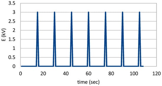
Figure 5.
Time course of pulses used on the flow cuvette to execute electroporation.
To verify the transfer of magnetic nanoparticles, Prussian blue staining was used to visualize them into the cytoplasm of microalgae cells (Figure 6a).

Figure 6.
Prussian blue staining. (a) Nonelectroporated cells stained with Prussian blue. (b) Low magnification (40×) of electroporated cells stained with Prussian blue. (c) High magnification (100×) of electroporated cells stained with Prussian blue, which turns blue in the presence of iron inside cells. Bar size: 5 μm.
Images from an optical microscope verified that the Prussian blue reagent turned blue into the cytoplasm of S. almeriensis (Figure 6a). Since iron is not normally present in the S. almeriensis cytosol (Figure 6b), the fact that we detected a blue colour inside the cell indicated that iron oxide nanoparticles entered the cells’ body. Furthermore, by putting permanent magnets in the vicinity of transformed cells, it was possible to attract them towards the tube walls.
To verify the presence of fluorescent siRNA oligo inside S. almeriensis cells (Figure 7a,d), a fluorescent microscope was used. The nuclei of cells were counterstained using a Hoechst stain (Figure 7b,e). The successful introduction of siRNA inside S. almeriensis cells was confirmed by the green fluorescence (Figure 7c,f) generated by the fluorophore linked to the siRNA.
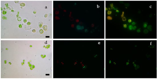
Figure 7.
(a,d) Bright field microalgae cells; (b,e) nuclei are stained with fluorescent Hoechst stain (cyan). The red colour in cells is due to the autofluorescence of microalgae cells; (c,f) siRNA oligos emit fluorescent green light. Bar size: 10 μm.
4. Conclusions
We realized a low-cost, easy-to-construct continuous flow electroporator cuvette compatible with the Bio-Rad MicroPulser Electroporator. The functionality of the device was proven by two means. First, microalgae cells were magnetically transformed by introducing magnetic nanoparticles in their cytoplasm and their presence confirmed by Prussian blue staining as well as by attracting them with a magnet. Second, in a separate experiment, fluorescent siRNA oligos were introduced in the cytoplasm of the same cell system. The emission of a green light was observed in the cytoplasm of the transfected cells, thus confirming the proper internalization of siRNA molecules. The electroporation flow cuvette can be sterilized, if necessary, and provide a high-throughput workflow. However, such flow cuvettes are meant for a single use. After their assembly, we perform several washes with 95% ethanol in order to remove impurities and microorganisms. Our flow cuvette electroporation method could be used not only for research purposes but also for biotechnological and industrial applications that require to transform high volumes of cultured cells such as the cultivation of magnetically modified microalgae in bioreactors. The new system described, in contrast to the standard cuvettes, provides the ability to electroporate big volumes of cells without demanding the presence of a user through the process. This enables a high transformation productivity, opening the road for numerous biotechnological applications. The accuracy of the device is not high (since some cells may receive zero, two or more electric pulses) but it can be suitable for bulk applications where the quantity of the transformed cells is important even if there are cells in the culture that did not receive foreign material in their cytoplasm. In other applications, such as the production of magnetic cells, a selection method could be introduced in order to enrich the transformed cells and overcome potential low-efficiency issues.
Author Contributions
All authors contributed to the study conception and design. More specifically, the work of each author was as follows: conceptualization, A.F., G.B. and A.B.; methodology, A.F., G.B., M.S. and A.B.; software, G.B. and A.G.; validation, A.F.; formal analysis, M.S., G.B. and A.F.; investigation, G.B., M.S., A.G. and A.F.; resources, A.B., E.H. and F.K.; data curation, A.F. and M.S.; writing—original draft preparation, G.B., A.F. and M.S.; writing—review and editing, A.F. and E.H.; visualization, A.F., G.B. and A.G.; supervision, E.H. and F.K.; project administration, A.F.; funding acquisition, A.F. and E.H. All authors have read and agreed to the published version of the manuscript.
Funding
The research leading to these results received funding from Operational Programme Competitiveness, Entrepreneurship and Innovation 2014–2020 (EPAnEK) under grant agreement no. T1EDK-04223.
Institutional Review Board Statement
Not applicable.
Informed Consent Statement
Not applicable.
Data Availability Statement
Data is contained within the article.
Acknowledgments
All authors acknowledge the assistance of Eleni Alexandratou and thank her for providing the fluorescent microscope and help with the fluorescence images acquisition.
Conflicts of Interest
The authors declare no conflict of interest.
References
- Kim, J.; Hwang, I.; Britain, D.; Chung, T.D.; Sun, Y.; Kim, D.H. Microfluidic Approaches for Gene Delivery and Gene Therapy. Lab Chip 2011, 11, 3941–3948. [Google Scholar] [CrossRef]
- Schnoor, M.; Buers, I.; Sietmann, A.; Brodde, M.F.; Hofnagel, O.; Robenek, H.; Lorkowski, S. Efficient Non-Viral Transfection of THP-1 Cells. J. Immunol. Methods 2009, 344, 109–115. [Google Scholar] [CrossRef] [PubMed]
- Goomer, R.S.; Deftos, L.J.; Terkeltaub, R.; Maris, T.; Lee, M.C.; Harwood, F.L.; Amiel, D. High-Efficiency Non-Viral Transfection of Primary Chondrocytes and Perichondrial Cells for Ex-Vivo Gene Therapy to Repair Articular Cartilage Defects. Osteoarthr. Cartil. 2001, 9, 248–256. [Google Scholar] [CrossRef] [PubMed]
- Fan, Z.; Liu, H.; Mayer, M.; Deng, C.X. Spatiotemporally Controlled Single Cell Sonoporation. Proc. Natl. Acad. Sci. USA 2012, 109, 16486–16491. [Google Scholar] [CrossRef] [PubMed]
- Tomizawa, M. Sonoporation: Gene Transfer Using Ultrasound. World J. Methodol. 2013, 3, 39. [Google Scholar] [CrossRef] [PubMed]
- Sharei, A.; Zoldan, J.; Adamo, A.; Sim, W.Y.; Cho, N.; Jackson, E.; Mao, S.; Schneider, S.; Han, M.J.; Lytton-Jean, A.; et al. A Vector-Free Microfluidic Platform for Intracellular Delivery. Proc. Natl. Acad. Sci. USA 2013, 110, 2082–2087. [Google Scholar] [CrossRef]
- Dixit, H.G.; Starr, R.; Dundon, M.L.; Pairs, P.I.; Yang, X.; Zhang, Y.; Nampe, D.; Ballas, C.B.; Tsutsui, H.; Forman, S.J.; et al. Massively-Parallelized, Deterministic Mechanoporation for Intracellular Delivery. Nano. Lett. 2020, 20, 860–867. [Google Scholar] [CrossRef]
- Froger, A.; Hall, J.E. Transformation of Plasmid DNA into E. Coli Using the Heat Shock Method. J. Vis. Exp. 2007, 6, 253. [Google Scholar] [CrossRef]
- Weaver, J.C. Electroporation: A General Phenomenon for Manipulating Cells and Tissues. J. Cell. Biochem. 2018, 51, 426–435. [Google Scholar] [CrossRef]
- Kingston, R.E.; Chen, C.A.; Rose, J.K. Calcium Phosphate Transfection. Curr. Protoc. Mol. Biol. 2003, 63, 9.1.1–9.1.11. [Google Scholar] [CrossRef]
- Hoekstra, S.A.D. Cationic Lipid-Mediated Transfection in Vitro and in Vivo. Mol. Membr. Biol. 2001, 18, 129–143. [Google Scholar] [CrossRef]
- Tryfona, T.; Bustard, M.T. Enhancement of Biomolecule Transport by Electroporation: A Review of Theory and Practical Application to Transformation of Corynebacterium Glutamicum. Biotechnol. Bioeng. 2006, 93, 413–423. [Google Scholar] [CrossRef] [PubMed]
- Jiang, C.; Davalos, R.V.; Bischof, J.C. A Review of Basic to Clinical Studies of Irreversible Electroporation Therapy. IEEE Trans. Biomed. Eng. 2015, 62, 4–20. [Google Scholar] [CrossRef] [PubMed]
- Maude, S.L.; Teachey, D.T.; Porter, D.L.; Grupp, S.A. CD19-Targeted Chimeric Antigen Receptor T-Cell Therapy for Acute Lymphoblastic Leukemia. Blood 2015, 125, 4017–4023. [Google Scholar] [CrossRef]
- Zhao, D.; Huang, D.; Li, Y.; Wu, M.; Zhong, W.; Cheng, Q.; Wang, X.; Wu, Y.; Zhou, X.; Wei, Z.; et al. A Flow-Through Cell Electroporation Device for Rapidly and Efficiently Transfecting Massive Amounts of Cells in Vitro and Ex Vivo. Sci. Rep. 2016, 6, 18469. [Google Scholar] [CrossRef] [PubMed]
- Teissié, J.; Rols, M.P. An Experimental Evaluation of the Critical Potential Difference Inducing Cell Membrane Electropermeabilization. Biophys. J. 1993, 65, 409–413. [Google Scholar] [CrossRef]
- Teissie, J.; Golzio, M.; Rols, M.P. Mechanisms of Cell Membrane Electropermeabilization: A Minireview of Our Present (Lack of ?) Knowledge. Biochim. Biophys. Acta Gen. Subj. 2005, 1724, 270–280. [Google Scholar] [CrossRef]
- Miklavčič, D. Handbook of Electroporation. Handb. Electroporation 2017, 1–4, 1–2998. [Google Scholar] [CrossRef]
- Huang, D.; Zhao, D.; Li, J.; Wu, Y.; Zhou, W.; Wang, W.; Liang, Z.; Li, Z. High Cell Viability Microfluidic Electroporation in a Curved Channel. Sens. Actuators B Chem. 2017, 250, 703–711. [Google Scholar] [CrossRef]
- Savvidou, M.G.; Ferraro, A.; Hristoforou, E.; Mamma, D.; Kekos, D.; Kolisis, F.N. Incorporation of Magnetic Nanoparticles into Protoplasts of Microalgae Haematococcus pluvialis: A Tool for Biotechnological Applications. Molecules 2020, 25, 5068. [Google Scholar] [CrossRef]
- Savvidou, M.G.; Ferraro, A.; Schinas, P.; Mamma, D.; Kekos, D.; Hristoforou, E.; Kolisis, F.N. Magnetic Immobilization and Growth of Nannochloropsis oceanica and Scenedasmus almeriensis. Plants 2022, 11, 72. [Google Scholar] [CrossRef] [PubMed]
- MicroPulser Electroporator. Available online: https://www.bio-rad.com/en-gr/product/micropulser-electroporator?ID=83527990-34fb-4b33-b955-ca53b57bf8b9 (accessed on 16 September 2022).
Publisher’s Note: MDPI stays neutral with regard to jurisdictional claims in published maps and institutional affiliations. |
© 2022 by the authors. Licensee MDPI, Basel, Switzerland. This article is an open access article distributed under the terms and conditions of the Creative Commons Attribution (CC BY) license (https://creativecommons.org/licenses/by/4.0/).