Abstract
In this paper, we propose an optimal design procedure for magnetically shielded rooms. Focusing on multi-layer ferromagnetic structures, where inner layers operate at very low magnetic field, we propose an identification method of the magnetic material characteristic in the Rayleigh region. A numerical model to simulate the shielding efficiency of a multi-layer ferromagnetic structure is presented and experimentally tested on different geometries and layer configurations. The fixed point iterative method is adopted to handle the nonlinearity of the magnetic material. In conclusion, the optimization of the design parameters of a MSR is discussed, using the Vector Immune System algorithm to minimize the magnetic field inside the room and the cost of the structure. The results highlight that a linear magnetic characteristic for the material is sufficient to identify the suitable geometry of the shield, but the nonlinear model in the Rayleigh region is of fundamental importance to determine a realistic shielding factor.
1. Introduction
Magnetically Shielded Rooms (MSRs) are closed spaces employed for the magnetic field mitigation in environments where sensitive electronic equipment is used (e.g., electronic microscopes and medical imaging devices) [1,2,3,4,5]. Figure 1a represents a commercial MSR. An effective design strategy for a MSR is the adoption of multiple closed ferromagnetic layers, not in contact with each other. The inner layer shields the residual field passing through the outer ones. A qualitative representation of the flux lines obtained using one layer and three layers is shown in Figure 1b,c, respectively. The aim is to minimize the magnetic field in a target region that often coincides with the center of the room [6,7].
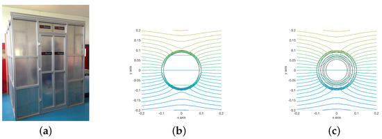
Figure 1.
Example of a commercial Magnetically Shielded Room (MSR) (a). Qualitative representations of the flux lines in a one-layered and a three-layered cylindrical shield (b,c).
Bearing all this in mind, it is apparent that the outermost layer is subject to the external magnetic field value, whereas the innermost layer is subject to a very low residual field. Therefore, the shielding material of some layers could operate in the Rayleigh region of the magnetic characteristic, where the permeability is a nonlinear function of the applied field, with values of the equivalent magnetic permeability considerably lower than those in the linear region. Developing the design of MSRs using the data provided by manufacturers, referred to the permeability measured in the linear region, could lead to a considerable overestimation of the shielding efficiency. To overcome this issue, some authors adopt a preliminary design procedure based on analytical expressions, provided for simple geometries as cylinders and spheres, experimentally verifying the final design [7,8]. Other authors propose to measure the curve at very low applied field and identify an equivalent permeability used to solve the field problem under linear assumption. [9,10,11].
This paper aims to define an identification procedure for the curve of the shielding material in the Rayleigh region, to define a design strategy based on a numerical simulation of the ferromagnetic shield able to handle the nonlinearity of the material, and to evaluate the design parameters of a MSR through a multi-objective optimization strategy, based on the Vector Immune System algorithm [12].
2. Material Modeling
The numerical simulation of a MSR involves a large volume, thin thickness of the shield layer, and air gap between layers. This is a multi-scale problem that can be hardly handled by classical formulations based on volume discretization like finite elements (Figure 2).
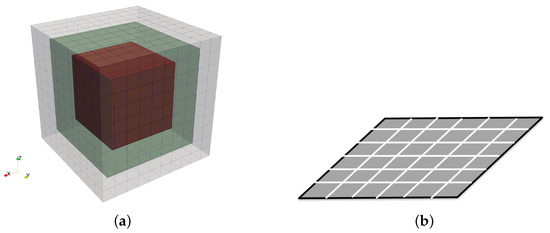
Figure 2.
Three-layered MSR mesh (a). Detail of the layer surface discretization (b).
In this paper, the thin shell approximation is adopted to model the thin ferromagnetic shield [13,14,15], therefore the metallic material is modeled and discretized as a surface. A magnetostatic integral formulation in terms of the magnetic field H and the magnetization M in the shell elements is used both for the linear and the nonlinear case. The fixed point iterative method is adopted to handle the nonlinear behavior of the material in the Rayleigh region [16].
2.1. Numerical Model of Ferromagnetic Shields
It is well known that the magnetic field at an arbitrary point of the space can be expressed as the sum of the external magnetic field and the contribution of the magnetized bodies [17]:
The external magnetic field is generated from the sources, i.e., source currents. The term can be related to the reduced scalar potential by knowing that, in a source free region, the relation holds true. Therefore, .
With reference to Figure 3, the reduced scalar potential can be computed by applying (2) and the field is obtained as its gradient as shown in (3) [18,19,20,21,22].
where is the magnetization.
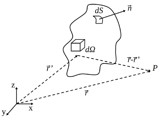
Figure 3.
Integration domain for the computation of .
By assuming a finite and homogeneous magnetic permeability, the term vanishes [21]. Therefore, considering that , the following relation between and is obtained:
The term is a scalar quantity called surface magnetic charge density and, when the shell approximation can be applied, some simplifications can be discussed. For a thin metallic sheet it is possible to assume that the magnetization lays on the same plane of the sheet [13,14,23], this behavior is also called shape anisotropy [24,25]. Figure 4 shows a shell element with its magnetization that is assumed to be uniform inside the volume. From the analysis of the 3D representation, it is apparent that the surface magnetic charge density vanishes on the top and bottom surfaces. Therefore, the integral in (4) can be computed only on the lateral surfaces. Moreover, considering the 2D shell element, the surface integral can be simplified in a line integral multiplied by the thickness t [14].
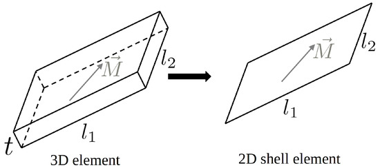
Figure 4.
From volume element to shell element representation when .
By introducing the magnetic susceptibility , the total magnetic field can be related to the magnetization , therefore, the substitution of (4) in (1) leads to
If the metallic layer is discretized in several rectangular of triangular elements, by applying a collocation method to the barycenter of each element, (5) leads to a linear system with the magnetization as unknown [13,14,15]:
Solving (6) the magnetization at each element of the shield is obtained. Afterward, the magnetic field in air can be computed as the sum of the source field and the one of the magnetized shield. The latter is computed using the equivalent surface charge density associated to each magnetized element according to (4) [14]. This approach can be used to surface meshes made of rectangular or triangular patches. In the first case, significant speed-up can be obtained exploiting the properties of the fast Fourier transform [15].
As explained earlier, the MSR is made of multiple layers that operate at different values of external magnetic fields. Some of the layers can operate in the Rayleigh region. Therefore, a nonlinear relation holds between the magnitudes of the magnetization and the magnetic field:
The nonlinearity can be handled with different iteration schemes. It is well known that the Newton–Raphson technique is usually fast, but some difficulties can arise in the case of magnetic characteristics presenting inflections. In contrast, the fixed point method is always convergent but its convergence rate can be slow compared to the Newton–Raphson technique [26,27]. In this paper, the fixed point technique is adopted to handle the nonlinearity. This method allows to split the nonlinearity in a linear term and a residual term [16,28]:
where is a constant value and is a residual term that describes the nonlinear dependence on H. Discretizing (8) at the barycentre of each element, and introducing the iterative procedure the following linear system can be obtained:
The residual term at the first iteration is set to zero, and the value is updated after each step with the following equation:
The iterative process is terminated when the residual term reaches a constant value up to a given tolerance. The convergence of the presented numerical method is ensured for any initial value of residual field. However, the constant term must be selected carefully [26,27]. In literature, the recommended value is
where and are the minimum and maximum slopes of the relation, respectively.
2.2. Identification of the Curve
The MSR considered in this paper is made of grain-oriented (GO) electrical steel. To take it into account in the simulations, its magnetic properties must be identified because, commonly, the manufacturers do not provide the magnetic characteristic in the Rayleigh region.
The identification is performed using a laboratory setup made of a single layer of GO electrical steel with thickness . The shape of the shield is a parallelepiped of size such as the one represented in Figure 5a. The material is placed in a pair of circular Helmholtz coils used to generate a homogeneous magnetic field at the frequency of (in order to exclude the influence of the earth magnetic field). The radius of the two coils is and the same value corresponds to the coil-to-coil axial distance. This geometry allows to maximize the homogeneity of the generated magnetic field. Figure 5b,c shows the calculated homogeneity volume considering a tolerance of 5%. The tolerance is defined as the deviation of magnetic field value compared to the target value at the center of the system.
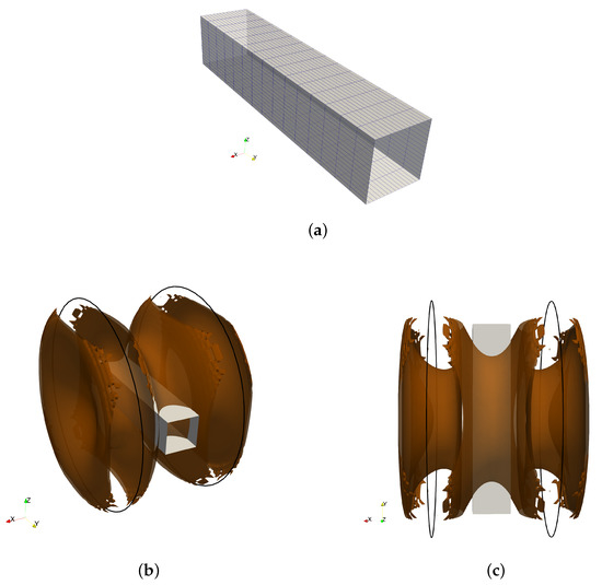
Figure 5.
Shield used in the identification procedure (a). Shield immersed in the magnetic field created by the Helmholtz coils. The surface represents the homogeneity volume considering 5% of tolerance (b,c).
The magnetic flux density is measured at the center of the system under different values of the applied external fields. The dimension of the magnetic field probe used to perform the measurement is small enough to be completely included in this homogeneity volume.
The same test conditions are reproduced using the numerical method presented above. The curve in the Rayleigh region adopted in the simulations is described by [29]
The relative permeability and the coefficient of the irreversible part of the magnetic flux density are the targets of the identification procedure [5]. An optimization of the two variables is performed, defining the objective function to be minimized as the mean square error between measured and simulated magnetic flux density values at the center of the shield. The optimal solution is obtained for and . With these values, the relationship represented in Figure 6a is obtained, whereas Figure 6b highlights the very good agreement between measured and simulated data.
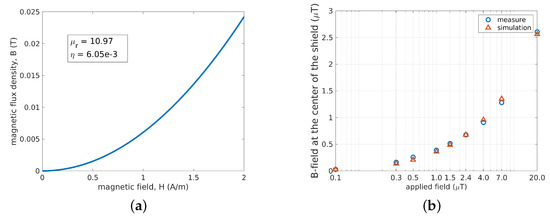
Figure 6.
curve in the Rayleigh region obtained with the identification procedure (a). Comparison of measured and simulated magnetic flux density at the center of the shield for different external field values (b).
2.3. Robustness of the Identification
To test the robustness of the identified material properties, other experimental tests are carried out. The aim is to understand if the relationship obtained earlier is still reliable considering a multi-layered shield (instead of a single layer) with a different geometry (cylindrical instead of parallelepiped). Therefore, a new shield is developed and tested with the same Helmholtz coils described above. The shield is made of three cylindrical layers with thickness of , the values of the radii are , , and . The complete shield structure is shown in Figure 7a. Six configurations are tested: (1) only the larger cylinder, (2) only the medium cylinder, (3) only the smaller cylinder, (4) larger and medium cylinders, (5) medium and smaller cylinders, and (6) shield with all cylinders. For the six configurations, the magnetic flux density at the center of the system is measured for different values of the applied magnetic field generated by the Helmholtz coils. The results are shown in Figure 7b. At the top of the figure, the values of the applied fields (, , , and ) are summarized, then the figure is divided into six frames corresponding to the shield configurations. Configurations from 1 to 6 are presented from the leftmost to the rightmost frame. Moreover, the inset in each frame makes it possible to easily understand the configuration under test. In particular, the inset represents the cross section of the shield where a dashed line is used to show the layers not considered in both measurements and simulations.
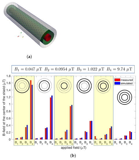
Figure 7.
Shield configuration adopted to test the identification robustness (a). Comparison of measured and simulated magnetic flux density at the center of the shield for different external field values and layer configurations (b).
The analysis of Figure 7b shows that measurements and simulation are in good agreement for all the configurations and for all the applied fields, proving the robustness of the identification procedure and the effectiveness of the numerical formulation.
3. Design of a MSR
This section proposes a methodology for the design of a magnetically shielded room considering real dimensions and highlighting the importance of nonlinear relations.
3.1. Optimization Method
The main objective is to minimize the magnetic flux density inside the room. Usually, the edge effects due to a local increase of the magnetic flux density close to the edges of the shield have to be taken into account in the design [30]. For this reason, it is a good approach to discretize the region of interest and minimize the average magnetic flux density rather than minimize the value at a single point or the maximum value [31]. However, in the case of a MSR, it is sufficient to focus on the center of the room because, as the volume is completely surrounded by the metallic material, common edge effects of flat and open shields are avoided. Therefore, in this paper, the first goal of the design is the minimization of the magnetic field at the center of the room. The second objective is to minimize the cost of the MSR, that is equivalent to minimize the volume of material used.
From simple and qualitative considerations, it is possible to conclude that the two objectives are conflicting and therefore a multi-objective optimization approach has to be adopted. In this paper, the Vector Immune System algorithm is used. All details can be found in [12] and the code is freely available at https://github.com/giaccone/VIS.
The optimization problem analyses a MSR with imposed external dimensions of . The five parameters of the optimization are represented in Figure 8:
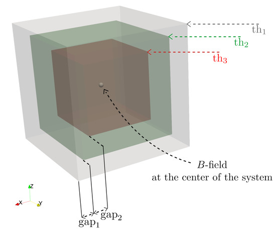
Figure 8.
Geometrical parameters of the optimization problem.
- the thickness of each layer: , , ;
- the gap between layers: , .
Finally, we recall that in a multi-objective optimization with conflicting objectives the output is not a single solution. The result is a set of trade-off solutions called Pareto optimal solutions or Pareto front [12].
3.2. Optimization Results
As a first attempt, the optimization is performed considering a linear characteristic of the shielding material. For the GO electrical steel, a relative permeability value of 30,000 is selected according to the literature [32]. In a second attempt, the relationship identified in previous sections is considered.
In both cases the geometrical parameters can be adjusted by the VIS algorithm in the following ranges:
- Fixed external dimensions: .
- Gap between layers values: .
- Layer thickness values: .
The Pareto fronts obtained in the linear and nonlinear case are represented in Figure 9. The x-axis represents the magnetic flux density at the center of the room and the y-axis the volume of the shield. As both objectives have to be minimized the utopia point corresponds to the origin of the axes.
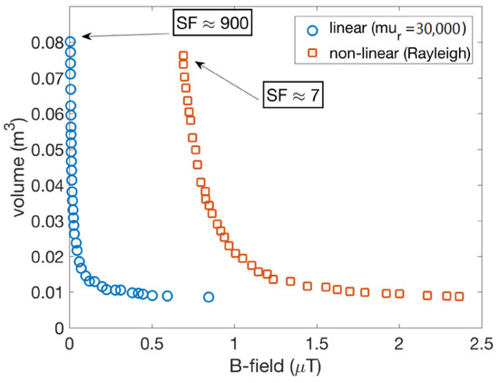
Figure 9.
Comparison of the Pareto front obtained from linear and nonlinear assumption. The shielding factors computed at the points of each Pareto front are highlighted.
The shapes of the two Pareto fronts are similar, however, it is apparent that with the linear assumption the magnetic flux density at the center of the room is much lower than the values obtained with the nonlinear material. By considering the shielding factor (SF; i.e., the ratio between the magnetic field without and with the shield) at the point of the Pareto front that minimizes the B-field, the linear assumption leads to 900 whereas the nonlinear assumption to 7. The significant variation of the SF highlights the important role of the correct identification of the magnetic characteristic.
To better understand differences and similarities of the two Pareto fronts, more details about the geometry are given in the following. First of all, it is observed that for each solution in the Pareto front the values of and (distances between layers) is always very close to , with a deviation lower than 5%. Further considerations can be done on the thicknesses. To this aim, let us consider Figure 10 where a qualitative Pareto front is represented. It is composed by all the solutions that can be observed moving from the point (, ) to the point (, ), as shown by the orange arrow. For each solution, it is possible to see the thickness values , , and , as presented in the plot. In the x-axis the solutions from (, ) to (, ) are listed and, for each solution 6 points can be read in the y-axis: , , and with linear assumption, and , , and with the nonlinear assumption. It is possible to observe that the thickness values obtained in the linear case are very similar to the ones obtained in the nonlinear case.
From the analysis of the optimization results it is possible to conclude the following.
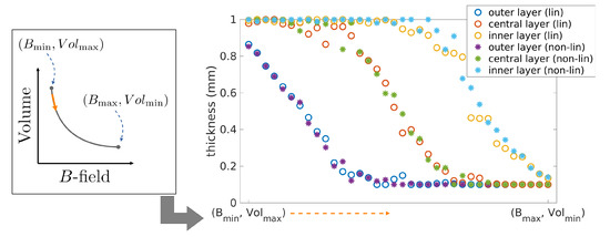
Figure 10.
Thickness values of the three layers obtained from linear and nonlinear assumption, corresponding to the Pareto front solutions, listed in the x-axis from the point (, ) to the point (, ), as shown by the orange arrow.
- The gap between layers is always maximized.
- A linear approximation seems to be sufficient to estimate the geometry of the MSR.
- After finding the optimal geometry, it is important to consider the nonlinear behavior of the material to estimate the real SF of the MSR.
4. Conclusions
The paper evaluates the optimal design of a multi-layer MSR, focusing on the modeling of ferromagnetic sheets at very low applied fields. An effective design procedure requires the accurate evaluation of the material characteristic in the Rayleigh region of the curve. To this end, an identification procedure of the magnetic characteristic is proposed, and the results are used within a numerical model able to simulate the shielding effect of metallic layers taking into account the nonlinearity of the material. The robustness of the identification procedure and the numerical model is tested through the simulation of different experimental setups. A multi-objective optimization is proposed to define the optimal choice of the thickness and the distance between shielding layers of a MSR, minimizing the magnetic field at the center of the room and the volume of magnetic material. The results highlight that a linear model of the magnetic characteristic is sufficient to identify the optimal geometry of the shield, but the nonlinear model of the Rayleigh region is required to evaluate the effective shielding factor of the MSR.
Author Contributions
All authors contributed equally to this work. All authors have read and agreed to the published version of the manuscript.
Funding
This research received no external funding.
Conflicts of Interest
The authors declare no conflict of interest.
References
- Harakawa, K.; Kajiwara, G.; Kazami, K.; Ogata, H.; Kado, H. Evaluation of a high-performance magnetically shielded room for biomagnetic measurement. IEEE Trans. Magn. 1996, 32, 5256–5260. [Google Scholar] [CrossRef]
- Trahms, L.; Burghoff, M. NMR at very low fields. Magn. Reson. Imaging 2010, 28, 1244–1250. [Google Scholar] [CrossRef] [PubMed]
- Sander, T.H.; Leistner, S.; Geisler, F.; MacKert, B.M.; Trahms, L. Characterization of motor and somatosensory function for stroke patients. Physiol. Meas. 2011, 32, 1737–1746. [Google Scholar] [CrossRef] [PubMed]
- Bork, J.; Hahlbohm, H.D.; Klein, R.; Schnabel, A. The 8-Layered Magnetically Shielded Room of the PTB: Design and Construction; Technical Report; Helsinki University of Technology: Espoo, Finland, 2001. [Google Scholar]
- Canova, A.; Freschi, F.; Giaccone, L.; Repetto, M. Numerical Modeling and Material Characterization for Multilayer Magnetically Shielded Room Design. IEEE Trans. Magn. 2018, 54, 1–4. [Google Scholar] [CrossRef]
- Mager, A. The Berlin Magnetically Shielded Room (BMSR), Section A: Design And Construction. In Biomagnetism; De Gruyter: Berlin, Germany, 2019; pp. 51–78. [Google Scholar] [CrossRef]
- Kelha, V.O.; Pukki, J.M.; Peltonen, R.S.; Penttinen, A.J.; Ilmoniemi, R.J.; Heino, J.J. Design, Construction, and Performance of a Large-Volume Magnetic-Shield. IEEE Trans. Magn. 1982, 18, 260–270. [Google Scholar] [CrossRef]
- Hasselgren, L.; Luomi, J. Geometrical aspects of magnetic shielding at extremely low frequencies. IEEE Trans. Electromagn. Compat. 1995, 37, 409–420. [Google Scholar] [CrossRef]
- Tashiro, K.; Sasada, I. A low-cost magnetic shield consisting of nonoriented silicon steel. IEEE Trans. Magn. 2005, 41, 4081–4083. [Google Scholar] [CrossRef]
- Liyi, L.; Zhiyin, S.; Donghua, P.; Jiaxi, L.; Feng, Y. An Approach to Analyzing Magnetically Shielded Room Permeability in Low Magnetic Field. IEEE Trans. Magn. 2014, 50, 1–4. [Google Scholar] [CrossRef]
- Yamazaki, K.; Kato, K.; Muramatsu, K.; Haga, A.; Kobayashi, K.; Kamata, K.; Fujiwara, K.; Yamaguchi, T. Incremental permeability of mu-metal in low magnetic fields for design of multi-layer-type of magnetically-shielded rooms. In Proceedings of the INTERMAG ASIA 2005: Digests of the IEEE International Magnetics Conference, Nagoya, Japan, 4–8 April 2005; p. 774. [Google Scholar] [CrossRef]
- Freschi, F.; Repetto, M. VIS: An artificial immune network for multi-objective optimization. Eng. Optim. 2006, 38, 975–996. [Google Scholar] [CrossRef]
- Chadebec, O.; Coulomb, J.; Bongiraud, J.; Cauffet, G.; Le Thiec, P. Recent Improvements for Solving Inverse Magnetostatic Problem Applied to Thin Shells. IEEE Trans. Magn. 2002, 38, 1005–1008. [Google Scholar] [CrossRef]
- Vuillermet, Y.; Chadebec, O.; Coulomb, J.; Rouve, L.L.; Cauffet, G.; Bongiraud, J.; Demilier, L. Scalar Potential Formulation and Inverse Problem Applied to Thin Magnetic Sheets. IEEE Trans. Magn. 2008, 44, 1054–1057. [Google Scholar] [CrossRef][Green Version]
- Giaccone, L.; Ragusa, C.; Khan, O.; Manca, M. Fast magnetic field modeling for shielding systems. IEEE Trans. Magn. 2013, 49, 4128–4131. [Google Scholar] [CrossRef]
- Giaccone, L.; Ragusa, C. Fast analysis of ferromagnetic shields by means of fixed point iterative technique. Phys. B Condens. Matter 2014, 435, 96–99. [Google Scholar] [CrossRef]
- Rogovoy, A.A.; Stolbov, O.V.; Stolbova, O.S. The Microstructural Model of the Ferromagnetic Material Behavior in an External Magnetic Field. Magnetochemistry 2021, 7, 7. [Google Scholar] [CrossRef]
- Kobayashi, M.; Ishikawa, Y. Surface Magnetic Charge Distributions and Demagnetizing Factors of Circular Cylinders. IEEE Trans. Magn. 1992, 28, 1810–1814. [Google Scholar] [CrossRef]
- Ozaki, K.; Kobayashi, M.; Rowlands, G. Surface Magnetic Charge Distribution of a Long, Thin Cylinder and Its Edge Singularity. IEEE Trans. Magn. 1998, 34, 2185–2191. [Google Scholar] [CrossRef]
- Ozaki, K.; Kobayashi, M. Surface Magnetic Charge Densities and Demagnetizing Factors for Rotating Astroids. IEEE Trans. Magn. 2000, 36, 210–215. [Google Scholar] [CrossRef]
- Soda, M.; Kobayashi, M.; Rowlands, G. Charge Densities and Inclination Angles of Magnetization on Various Surfaces of Rotational Symmetry. IEEE Trans. Magn. 2004, 40, 1763–1768. [Google Scholar] [CrossRef]
- Muscia, R. Equivalent magnetic charge in helicoidal magnets. J. Appl. Phys. 2008, 104, 103916. [Google Scholar] [CrossRef]
- Brunotte, X.; Meunier, G. Line element for efficient computation of the magnetic field created by thin iron plates. IEEE Trans. Magn. 1990, 26, 2196–2198. [Google Scholar] [CrossRef]
- Newell, A.; Williams, W.; Dunlop, D. A Two-Dimensional Micromagnetic Model of Magnetizations and Fields in Magnetite. J. Geophys. Res. 1993, 98, 9533–9549. [Google Scholar] [CrossRef]
- Volmer, M.; Neamtu, J. Computer simulation of magnetization curves in magnetic thin films. J. Optoelectron. Adv. Mater. 2003, 5, 319–324. [Google Scholar]
- Chiampi, M.; Chiarabaglio, D.; Repetto, M. An accurate investigation on numerical methods for nonlinear magnetic field problems. J. Magn. Magn. Mater. 1994, 133, 591–595. [Google Scholar] [CrossRef]
- Chiampi, M.; Chiarabaglio, D.; Repetto, M. An Improved Technique for Nonlinear Magnetic Problems. IEEE Trans. Magn. 1994, 30, 4332–4334. [Google Scholar] [CrossRef]
- Hantila, I. A method for solving stationary magnetic field in non-linear media. Rev. Roum. Des Sci. Tech. ÉLectrotechnique ÉNergÉTique 1975, 20, 397. [Google Scholar]
- Bozorth, R. Ferromagnetism; Wiley: Hoboken, NJ, USA, 1993. [Google Scholar]
- Bavastro, D.; Canova, A.; Freschi, F.; Giaccone, L.; Manca, M. Magnetic Field Mitigation at Power Frequency: Design Principles and Case Studies. IEEE Trans. Ind. Appl. 2015, 51, 2009–2016. [Google Scholar] [CrossRef]
- Del-Pino-López, J.C.; Giaccone, L.; Canova, A.; Cruz-Romero, P. Design of active loops for magnetic field mitigation in MV/LV substation surroundings. Electr. Power Syst. Res. 2015, 119, 337–344. [Google Scholar] [CrossRef]
- Mitigation Techniques of Power Frequency Magnetic Fields Originated from Electric Power Systems; Technical Report Worging Group C4.204; International Council on Large Electric Systems (CIGRE’): Paris, France, 2009; ISBN 978-2-85873-060-5.
Publisher’s Note: MDPI stays neutral with regard to jurisdictional claims in published maps and institutional affiliations. |
© 2021 by the authors. Licensee MDPI, Basel, Switzerland. This article is an open access article distributed under the terms and conditions of the Creative Commons Attribution (CC BY) license (http://creativecommons.org/licenses/by/4.0/).