Article

Study on the Influence of Hall Effect on the Performance of Disk Generation Channel

School of Aeronautics and Astronautics, Guilin University of Aerospace Technology, Guilin 541004, China
*
Authors to whom correspondence should be addressed.
Magnetochemistry 2025, 11(3), 19; https://doi.org/10.3390/magnetochemistry11030019
Submission received: 27 November 2024 / Revised: 19 February 2025 / Accepted: 27 February 2025 / Published: 4 March 2025

Abstract

:
Compared to the Faraday-type power generation channel structure, the disk-type power generation channel offers several advantages, including a simpler structure, higher enthalpy extraction efficiency, and greater power density. These features effectively reduce the requirements for magnetic systems, making it a priority development direction for space nuclear magnetohydrodynamic (MHD) power generation channels. The disk power generation channel utilizes the Hall effect for power generation; however, the impact of the Hall effect on current distribution, plasma characteristics, conductivity, and other parameters within the disk-type power generation channel remains unclear. A mathematical model of a plasma MHD power generation channel was established using a He/Xe mixed gas as the working fluid. Numerical simulations were conducted to investigate the performance of the disk-shaped power generation channel under varying Hall parameters. The research findings indicate that a strong circular Faraday current forms near the anode, leading to significant anode erosion. The Hall effect significantly influences plasma stability, with stronger Hall effects resulting in reduced plasma stability. Conductivity between the electrodes gradually increases from the anode to the cathode, becoming more pronounced as the Hall effect intensifies. By enhancing the Hall effect, the enthalpy extraction rate is significantly improved, electrical efficiency asymptotically approaches 50%, and the overall performance of the power generation channel is substantially enhanced.

1. Introduction

The disk-shaped magnetohydrodynamic (MHD) generator is a closed-cycle power generation system that utilizes an inert gas as the working fluid for electricity generation. The disk-shaped power generation channel boasts a simple structure, lacks a rotating mechanism, and achieves direct thermal-to-electric conversion with high efficiency. This system can provide a reliable and long-lasting electrical energy supply for deep space exploration activities, making it an ideal power source for applications such as deep space probes, electric propulsion vehicles, and extraterrestrial energy bases. Numerous theoretical and experimental studies have been conducted on disk-shaped power generation, particularly focusing on aspects such as working fluid ionization, seed concentration, and power generation channel structure.
Tanaka M’s research demonstrated that, even with a small amount of pre-ionization energy, Joule heating upstream of the channel can maintain effective plasma ionization. An argon generator with a magnetic field strength of 4 T achieves an enthalpy extraction rate of 25% and an isentropic efficiency of 65%. High-speed digital camera images of the plasma structure reveal no significant ionization instability within the experimental channel, and the plasma brightness exhibits radial expansion [1,2,3]. A disk-shaped power generation channel featuring swirl blades at the inlet was proposed and subjected to numerical simulation studies. Numerical analysis revealed that the electron temperature between conductive swirl blades is higher than that between insulating swirl blades. However, this temperature difference diminishes near the annular electrode region. Consequently, the performance of the disk-shaped power generation channel using conductive and insulating swirl blades is nearly identical [4]. Additionally, a working fluid scheme involving the addition of Xe seeds to Ne has been proposed to investigate the plasma characteristics of different seed concentrations and their effects on power generation channel performance. For instance, adding a small amount of Xe to Ne can enhance conductivity and the enthalpy extraction rate in the disk-shaped power generation channel, leading to improved performance. However, when the seed concentration increases to 5%, the performance of the power generation channel begins to deteriorate [5,6].
The NASA Marshall Space Flight Center and Nagaoka University of Technology have collaborated to propose a megawatt-class disk magnetohydrodynamic (MHD) power generation system using a He/Xe mixed gas as the working fluid [7]. They concluded that the optimal power-to-mass ratio is highly dependent on the overall scale of the power generation system. Specifically, when the net output power reaches 1 MW, a mass–power ratio of 3 kg/kW can be achieved. When the net output power exceeds 3 MW, the mass–power ratio decreases to below 2 kg/kW. Stanford University and the University of Illinois conducted experimental research on argon gas ionization [8]. Using spectral measurement techniques, they determined the three-body recombination rate coefficient of argon electrons and ions. The experimental results were consistent with those predicted by the Saha equation. Additionally, the shock tube method for plasma generation has been widely adopted by researchers. For instance, Vasil’eva R V et al. utilized this method to investigate a disk-shaped power generation channel. Their study found that the development of ionization instability increases the average electrical conductivity of the plasma [9].
China has also conducted extensive numerical simulations and experimental research on plasma magnetohydrodynamic (MHD) power generation. Ling Wenhui’s study revealed that the number of electrodes and magnetic field strength in the power generation channel significantly influence the deceleration of the channel airflow. His findings indicate that higher magnetic field strength results in a more pronounced reduction in Mach number within the channel. Increasing the number of electrodes can reduce Joule heat dissipation, thereby enhancing the electrical efficiency of the power generation channel [10]. Liu Feibiao experimentally investigated a Faraday-type power generation channel using an Ar/Cs mixed gas as the working fluid and successfully completed the principle verification of Faraday-type MHD power generation. Under experimental conditions with a magnetic field strength of 1 T, a power output of 194 W was achieved, corresponding to a power density of 866 kW/m3 [11]. Lu Ziyin utilized detonation shock tube technology to ionize inert gases and conducted experimental research on inert gas MHD power generation, verifying the feasibility of detonation-driven shock tube technology in this context [12]. Zhu Peiqi from the Institute of Electrical Engineering of the Chinese Academy of Sciences also investigated the performance characteristics of the disk generator [13].
Current research on the disk-shaped power generation channel primarily focuses on aspects such as channel structure, working fluid type, ionization methods, and system design. In the disk-shaped power generation channel, there exists a complex interaction between the Hall parameter and plasma characteristics. Variations in the Hall parameter not only affect current distribution but also lead to changes in parameters such as the Lorentz force, static temperature, and fluid velocity within the power generation channel, thereby altering the plasma characteristics. Conversely, changes in the plasma characteristics also influence the Hall parameter, ultimately causing fluctuations in the electrical energy output of the power generation channel. Therefore, this study investigates the relationship between the Hall parameter and plasma characteristics by setting the Hall parameter to 2.0, 4.0, 6.0, and 8.0. According to the mechanism of the Hall effect, a stable Hall parameter can achieve a stable current distribution, thereby revealing the patterns of plasma characteristic changes under stable current conditions. By adjusting the value of the Hall parameter, different current distribution patterns can be obtained, allowing for an analysis of the degree of influence of Hall parameter variations on plasma characteristics. This research aims to explore control methods for plasma stability in the disk-shaped power generation channel, optimize its structural design, and enhance its power generation performance.

2. Research Models and Computational Methods

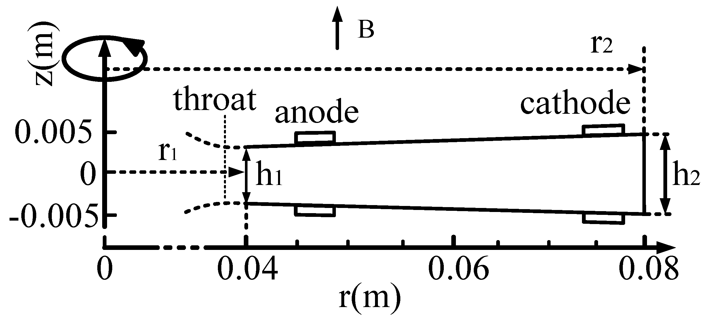
2.1. Research Object and Power Generation Principle

Space nuclear magnetohydrodynamic (MHD) power generation technology holds promising application prospects in extraterrestrial energy bases, power sources for deep space probes, electric propulsion vehicles, and other fields. Numerous research institutions and researchers have conducted detailed studies on its power generation principles, channel structures, plasma characteristics, and other aspects. The current mainstream power generation structures include disk-shaped and Faraday-type power generation channels. Due to their simple structure and high power density, disk-shaped power generation channels are considered the most ideal configuration for deep space exploration activities. The 1/4 section model of the disk-shaped generator is shown in Figure 1. In this study, the coordinate origin of the research model depicted in Figure 1 is located at the geometric center of the disk-shaped power generation channel. The external magnetic field B is oriented along the z-axis. Plasma enters through the annular inlet and exits via the annular outlet, forming an annular Faraday current Jθ under the influence of the magnetic field. During this process, ions and electrons experience opposite Lorentz forces along the radial direction, causing them to move in opposite directions and generating a Hall voltage between the anode and cathode. When externally loaded, a Hall current Jr is induced, thereby achieving Hall power generation.
Figure 2 illustrates the r-z plane, with a throat height of h1 = 0.006 m, an outlet height of h2 = 0.008 m, a circular entrance radius of r1 = 0.04 m, and an outlet radius of r2 = 0.08 m. The geometric center of the disk-shaped generator is located at the coordinate origin.

2.2. Calculation Method

2.2.1. Maxwell’s Equations

Plasma magnetofluid flows in a magnetic field, generating a current through electromagnetic induction. The electric field, magnetic field, current, and charge density are governed by the Maxwell equations. The subsequent section presents the Maxwell equations [14]:
× E = B t
× H = J + D t
B = 0
D = ε E
H = 1 μ m B
The generalized Ohm’s equation is
J + β B J × B = σ E + U × B
where β is the Hall parameter, σ is the conductivity, μm is the magnetic permeability, ε is the dielectric constant, D is the potential shift, H is the magnetic field strength, and B is the magnetic flux density.

2.2.2. Potential Equation

We employ the electric potential method for solving, and the governing equation is presented as follows:
J = 0
× E = 0
Derived from Equation (8):
E r = ϕ r , E z = ϕ z
where ϕ is the potential, and the potential equation can be derived from Equations (6) and (7):
σ ϕ = σ U × B + β U
The potential distribution of the disk-shaped power generator can be derived from the potential equation. Subsequently, the current distribution can be obtained using Equation (8) and the generalized Ohm’s law. Finally, parameters such as the Lorentz force, Joule heating, and electric power can be calculated. Given that the external magnetic field is oriented along the z-axis, the equation for solving the current density can be simplified as follows:
J r = σ / 1 + β 2 ϕ / r + u θ B z + β u r B z
J θ = σ / 1 + β 2 ϕ / r + β u θ B z u r B z
J z = σ ϕ / z

2.2.3. Nonequilibrium Ionization Model

We assume that the nonequilibrium ionization model incorporates two distinct temperature states: the heavy particle temperature Tg and the electron temperature Te. Based on this assumption, we can formulate a nonequilibrium ionization model for He/Xe mixed gases [15,16,17,18].
(1)
The charged-particle conservation equation:
n i + t + n i + u = k f i n e n i k r n e 2 n i +
n e = n i +
(i = Noble gas, ion), where ni+ is the particle number density of helium or xenon ions, ni is the atomic number density of helium or xenon atoms, ne is the electron number density, kfi is the ionization rate coefficient, and kr is the three body recombination rate coefficient [18].
k r = k r h k r o k r h + k r o   ( T e > 4000   K )
k f i = 2 k r g i g h 2 π m e k T e h 2 3 / 2 exp e ε i k T e
in which
k r h = 1.09 × 10 20 T e 9 / 2
k r o = 1.21 × 10 35 T e 2 exp 5.53 × 10 4 T e
where gi is the ground state statistical weight of helium or xenon ions, gh is the ground state statistical weight of helium or xenon atoms, me is the electron mass, Te is the electron temperature, h is the Planck constant, εi is the ionization potential of helium or xenon atoms, and k is the Boltzmann constant.
(2)
Conservation of electron energy
U e t + U e u e = J 2 σ 3 n e m e k T e T g n v e n m n ε i n i +
U e = 3 2 n e k T e + i ε i n i +
(n = He, Xe, He+, Xe+, i = He+, and Xe+), here Ue is the electron energy, and ven is the averaged collision frequency of electrons with atoms or ions.
v e n = n n n Q e n C e
where nn is the number density of atoms and ions, Qe−n is the cross-sectional area of collisions between electrons and atoms or ions, and Ce is the average velocity of electrons.
C e = 8 k T e / π m e
Q e n = 4 3 × 5.65 × 10 20 , n = H e 4 3 × 0.4 × 10 17 , n = X e 6 π e 2 12 π ε 0 k T e 2 ln 12 π ε 0 k ε 2 1.5 T e 3 n e , n = H e + ,   X e +
where e is the amount of charge carried by an electron, and ε0 is the vacuum dielectric constant. The conductivity can be calculated using the following formula:
σ = e 2 n e m e v e n β = e B m e v e n

2.2.4. Governing Equations

Due to the relatively small induced magnetic field generated in the power generation channel, it can be neglected. Considering the influence of the Lorentz force and Joule heating on the flow field, the Navier–Stokes equations are written as follows [19].
Continuous equation:
ρ t + ρ u = 0
Momentum equation:
t ρ u + ρ u u = J × B p p L
Energy equation:
E s t + E s + p u = J 2 σ + u J × B Q L
where p is the static pressure, Es is the total energy of the mixed gas, QL is the heat loss caused by thermal conduction, and pL is the static pressure loss caused by friction.
p L = 1 2 ρ n C f 4 π r A u
C f = 0.064 σ B 2 ρ u R e 0.2

2.2.5. Turbulence Model

The Spalart–Allmaras (S–A) turbulence model is one of the primary turbulence models used in engineering calculations, particularly well-suited for simulating the gas flow. It requires solving only one transport equation, offering advantages such as fast computation speed and accurate results for simulations involving inverse pressure gradients. Due to its high reliability in supersonic gas flow calculations, the S–A turbulence model is widely adopted. Therefore, we utilize the S–A turbulence model for our simulation calculations.

2.3. Performance Parameters of the Power Generator

The key performance metrics for evaluating a magnetohydrodynamic (MHD) generator encompass the enthalpy extraction rate, electric power density, electrical efficiency, and power output.
(1)
Enthalpy extraction rate
The enthalpy extraction ratio is defined as the ratio of the electrical energy output by the generator to the input thermal energy. The corresponding calculation expression is presented as follows:
η g = W g W 0 = V J E d V m 0 c p T 0 + u 0 2 2
(2)
Electric power density
The electric power density signifies the electrical entric power density signifies the electrical energy output per unit volume in a magnetohydrodynamic (MHD) generator. The corresponding calculation formula is presented as follows:
P g = E J
(3)
Electric efficiency
Electrical efficiency is defined as the ratio of the effective electrical power extracted from the fluid to the electromagnetic braking power. This parameter is crucial for evaluating the performance of energy conversion. The corresponding calculation formula is presented as follows:
η e = J E u J × B
(4)
Electricity generation
Power output is a physical quantity that quantifies the electrical energy generated by a magnetohydrodynamic (MHD) generator. The corresponding calculation formula is presented as follows:
P 0 = V P g d V = V E J d V

2.4. Boundary Conditions

2.4.1. Grid Division of Power Generation Channels

The grid configuration for the disk-shaped generator utilizes structured grids, as illustrated in Figure 3. The mesh comprises a total of 254,408 cells, with 240 nodes in the circumferential direction, 78 nodes in the radial direction, and 15 nodes along the z-axis. The thickness of the first layer of grids adjacent to the wall is set to 0.0004 m, and the grid growth ratio is 1.02.

2.4.2. Boundary Conditions of the Object Surface

In consideration of the fluid’s viscosity, there is no velocity slip at the interface between the fluid and the object. As a result, the flow velocity of the fluid at the object’s surface adheres to the no-slip boundary condition:
u r = 0 ,   u z = 0
As for the boundary conditions for the elliptic partial equation governing the electrical potential ϕ , the Dirichlet boundary condition is specified on the electrodes, ( ϕ = 0 on the anode, and ϕ = V H a l l on the cathode).
In this study, we examine four cases of the Hall parameter: β = 2, 4, 6, and 8. The wall is modeled as an insulated surface with a temperature of 1000 K, which prevents current lines from penetrating it. The electrode is represented as a perfect conductor with zero voltage drop, ensuring that the condition e·E = 0—or, equivalently, J·e = 0—is satisfied, where e denotes the unit normal vector on the wall.

2.4.3. Import/Export Boundary Conditions

The annular inlet of the channel is configured as a pressure inlet boundary condition with a total inlet pressure of 0.6 MPa, a static pressure of 0.1 MPa, a total temperature of 2500 K, and a static temperature of 1227 K. Helium (He) serves as the working fluid, with xenon (Xe) as the seed material at a concentration of 3 × 10⁻⁵. An external magnetic field is applied along the positive z-axis, with a magnetic field strength of B = 1 T. According to previous studies [20], maintaining the electron temperature between 8000 K and 9000 K ensures relative stability in the electron number density of He/Xe plasma, which is critical for the stability of the power generation channel performance. Therefore, setting the inlet electron temperature to 8000 K is appropriate. The outlet is defined as a pressure outlet boundary condition with a gauge pressure of 0 Pa and a backflow total temperature of 300 K.

3. Methods and Model Validation

The accuracy of the computational model we have established is crucial for our research and must be validated. To this end, we adopted Murakami’s power generation channel model for verification, replicating his experimental setup and comparing our results with his findings [21]. The comparison results are summarized as follows. In the electron temperature comparison (Figure 4), the maximum discrepancy occurs at an r-axis position of 58 mm. At this location, Murakami’s simulation yields a temperature of 5500 K, whereas our simulation results in a temperature of 5310 K, resulting in a deviation of only 3.5%.
Figure 5 illustrates the comparison results for the ionization degree, with the maximum discrepancy occurring at an r-axis position of 97 mm. At this location, Murakami’s simulation yields an ionization degree of 0.13%, while our simulation results in an ionization degree of 0.129%, resulting in a deviation of only 0.0769%.
In the conductivity comparison results (Figure 6), the maximum discrepancy in conductivity is observed at an r-axis position of 57 mm. At this location, Murakami’s reported value is 550 S/m, whereas our simulation yields a result of 524 S/m, resulting in a deviation of 4.7%.
The comparison results presented in Figure 7 indicate that the maximum deviation in static temperature is observed at a horizontal position of 80.5 mm, with a deviation of 4.0%. At this location, Murakami’s simulation result is 2500 K, whereas our simulation yields a result of 2400 K. The comparison results for the Mach number (Figure 8) show that the maximum deviation in the Mach number is 2.5%, occurring at a horizontal position of 56 mm. At this point, Murakami’s simulation result is 1.2, while our simulation yields a value of 1.23.
Based on the comparison data from the previous five groups, within the allowable error range, we can conclude that the ionization model established in this study is accurate.

4. Calculation Results and Analysis

4.1. Structure of Supersonic High-Temperature Helium/Xenon Mixture Flow

As detailed in Section 2.4.3, the inlet static temperature is set at 2500 K, and the static pressure is maintained at 0.1 MPa. Within the disk generator channel, the static pressure decreases from 0.1 MPa at the inlet to 0.02 MPa at the exit due to gas expansion within the channel (Figure 9). Throughout this process, the static pressure exhibits a consistent decreasing trend, with the most significant reduction occurring between the inlet and the anode, followed by a gradual decrease from the anode to the outlet. The analysis reveals that higher initial pressure facilitates a more rapid conversion of pressure energy into kinetic energy, leading to a steeper decline in static pressure near the inlet and a relatively slower decrease downstream. As illustrated in Figure 9, an increase in the Hall parameter results in increasingly irregular static pressure contours, indicating that the Hall effect significantly influences the stability of the flow field structure. Specifically, a weaker Hall effect promotes a more stable flow field, while a stronger Hall effect introduces greater instability. During the flow through the channel, the plasma magnetofluid is influenced by the Lorentz force F. When the Hall effect is negligible, the Lorentz force acts radially. As the Hall effect intensifies, the Lorentz force gradually deflects toward the tangential direction, resulting in an increasing tangential component Fθ. The magnitude of Fθ increases with the strength of the Hall effect, thereby enhancing the instability of the flow field structure.
As illustrated in Figure 10, the expansion of the channel results in an increase in the Mach number, with the magnitude of this increase remaining consistent across different Hall parameter conditions. The Mach number rises from 1.8 at the inlet to 3.0 at the channel exit due to gas flow through the expanding channel. In this study, the channel’s expansion ratio is fixed, and the applied magnetic field and potential are uniform throughout the channel, ensuring a consistent radial Lorentz force Fr acting on the plasma. Under these conditions, the increase in Mach number remains largely unchanged. However, the tangential Lorentz force Fθ, which increases with higher Hall parameters, causes the Mach number distribution to become increasingly uneven. This unevenness reflects the destabilization of the flow field structure due to the influence of Fθ.
Through the analysis of Figure 9 and Figure 10, it can be concluded that the Hall effect significantly influences the tangential Lorentz force generated within the power generation channel. Specifically, the intensity of the Hall effect is positively correlated with the magnitude of the tangential Lorentz force, which, in turn, critically affects the stability of the flow field structure. For a magnetohydrodynamic (MHD) generator, a stable flow field structure is essential for ensuring optimal performance. Therefore, in the design of a disk-type generator, the intensity of the Hall effect should be maintained within an appropriate range: excessively low values may impede effective electrical energy output, while excessively high values can disrupt the flow field structure, thereby degrading the overall performance of the generator.

4.2. Distribution of the Current Lines

Figure 11 illustrates the distribution of the current lines under different Hall parameters in the z = 0 section of the disk-shaped power generation channel. Analysis reveals that, near the annular anode, the Faraday effect is pronounced, resulting in a stronger annular current and a weaker radial current. As one moves from the anode toward the cathode, the Faraday effect gradually diminishes, while the Hall effect becomes increasingly dominant, leading to a gradual decrease in the annular current and an increase in the radial current. Near the cathode, the Hall effect is most significant; particularly, when the Hall parameter β = 8.0, the current lines are nearly perpendicular to the outlet.
According to the principle of the Hall effect, two types of currents exist in the disk-shaped power generation channel: the circumferential Faraday current Jθ and the radial Hall current Jr. The radial Hall current Jr flows from the anode to the cathode. Given that the distance between the anode and cathode is fixed and the external load remains constant, it can be assumed that the voltage and resistance along this path remain unchanged, resulting in a constant magnitude of the radial Hall current Jr. The circumferential Faraday current Jθ forms a closed loop, with its circular path increasing as the radius increases. Consequently, the circumferential resistance also increases with the radius, leading to a decrease in the circumferential Faraday current Jθ as the radius grows. By analyzing the trends in both the Hall current and the Faraday current, it can be observed that, within the disk-shaped power generation channel, as one moves from the anode to the cathode and the radius increases, the direction of the combined current gradually shifts from the circumferential to the radial direction. Near the anode, electrical conductivity is relatively high (Figure 14a), and the resistance is relatively low, resulting in a strong Faraday current that forms a significant annular Faraday current. Conversely, near the cathode (0.070 m < r < 0.075 m), electrical conductivity decreases (Figure 14a), the radius is larger, and the resistance increases rapidly, causing the Faraday current to diminish significantly. This rapid increase in resistance near the cathode results in a more pronounced shift of the current towards the radial direction.
Based on the aforementioned analysis, it can be concluded that, with a constant Hall parameter, an increase in the radius of the disk-shaped power generation channel leads to a diminishing Faraday effect, causing the current lines to gradually deflect toward the radial direction until they are nearly perpendicular to the outlet.
Due to the formation of annular Faraday currents near the anode, local high temperatures are likely to occur in this region, as illustrated in Figure 12a. According to the circuit principles, the currents through the anode and cathode are equal. However, due to the shorter circumference of the anode compared to the cathode, the current density at the anode is higher, as shown in Figure 12b. Furthermore, the gradient of the current density within the red circle at the anode is greater than that within the blue circle, leading to an uneven current distribution across the anode, with a higher current on the right side compared to the left side. The elevated current density and uneven current distribution exacerbate the deterioration of the anode’s working environment and, in severe cases, may result in electrode erosion. Therefore, optimizing the anode structure to suppress Faraday currents can enhance the service life of the anode electrode.

4.3. Analysis of the Plasma Distribution

The stability of the plasma structure significantly influences the performance of the power generation channels. According to the results shown in Figure 13, from the channel entrance to the anode (0.04 m ≤ r < 0.045 m), the low current density leads to a decrease in electron temperature (Figure 12b), with the electron–ion recombination rate (kr) exceeding the ionization rate (kfi). Consequently, the degree of ionization exhibits a decreasing trend (Figure 13a). Near the anode (0.045 m < r < 0.05 m), the circular Faraday current is relatively strong (Figure 11), resulting in higher electron temperatures and a gradual increase in the degree of ionization (Figure 13a).
However, the degree of ionization shows distinct variations under different Hall parameters between the anode and cathode. When the Hall parameter β = 2.0, the ionization degree exhibits minimal variation, leading to a relatively stable plasma structure within the channel. As the Hall parameter increases, the radial ionization degree fluctuates more significantly, causing greater instability in the plasma structure between the electrodes (Figure 13a).
In the disk-shaped power generation channel, both circumferential Faraday currents and radial Hall currents exist. The circumferential Faraday current subjects charged particles in the plasma to a radial Lorentz force, while the radial Hall current subjects them to a tangential Lorentz force. As the Hall parameter increases, the Hall current also increases, enhancing the tangential Lorentz force and intensifying the disturbance of the plasma magnetohydrodynamic flow (Figure 10). This disturbance gradually deteriorates the stability of the plasma magnetohydrodynamic flow, resulting in an unstable plasma magnetohydrodynamic structure and causing fluctuations in the plasma ionization degree curve. The more significant the Hall effect, the greater the fluctuation amplitude of the ionization degree curve. Consequently, the Hall effect plays a crucial role in determining the stability of the plasma structure within the channel. A stronger Hall effect correlates with more pronounced plasma instability.
The expansion of the channel plays a dominant role in the variation of the electron number density, leading to an overall downward trend in electron number density within the channel (Figure 13b). However, within the intervals 0.048 m < r < 0.053 m and 0.062 m < r < 0.065 m, the electron number density exhibits a slight increase. Analysis in conjunction with the ionization degree variation trend (Figure 13a) indicates that the rise in ionization degree within these intervals is the primary factor responsible for the increase in electron number density.
From the distribution of electrical conductivity along the r-axis (Figure 14a), it can be observed that the trend of conductivity changes under different Hall parameter conditions is generally consistent. Specifically, from the inlet to the anode and, subsequently, from the anode to the cathode, the conductivity initially increases and then decreases. Under different Hall parameter conditions, the variation trend of the electron-heavy particle collision frequency remains largely consistent. Specifically, within the range 0.045 m < r < 0.05 m, the collision frequency exhibits a gradual increase, whereas, in other regions, it demonstrates a gradual decrease (Figure 14b). It is important to note that, based on the calculation formula for the Hall parameter (Equation (22)), each Hall parameter corresponds to a specific average electron-heavy particle collision frequency. Consequently, the collision frequency determined by this Hall parameter represents a definite average value and should not be directly correlated with the local collision frequency depicted in Figure 14b.
Based on the variation in electron-heavy particle collision frequency (Figure 14b) and the relationship between conductivity, electron number density, and electron collision frequency ( σ = e 2 n e / m e v e n ), it can be concluded that, within the range 0.04 m < r < 0.07 m, the influence of electron-heavy particle collision frequency on conductivity is predominant, leading to an increase in conductivity. When r > 0.07 m, channel expansion results in a decrease in the electron number density, which subsequently dominates the change in conductivity. Due to the low current density from the inlet to the anode (Figure 12b), the electron temperature remains relatively low. Consequently, channel expansion leads to a reduction in gas density, which has a predominant effect on the frequency of electron-heavy particle collisions. As a result, the frequency of electron-heavy particle collisions gradually decreases, leading to a gradual increase in conductivity. Near the anode, due to the high current density, the electron temperature rises, and the influence of electron temperature on the frequency of electron-heavy particle collisions becomes predominant. Consequently, the frequency of electron-heavy particle collisions increases, resulting in a decrease in conductivity.
Within the range of 0.05 m < r < 0.07 m, channel expansion leads to a reduction in gas density, which significantly influences the frequency of electron-heavy particle collisions. Consequently, the collision frequency decreases, resulting in a gradual increase in conductivity. For r > 0.07 m, channel expansion causes a substantial reduction in electron number density, leading to a gradual decrease in conductivity.
From the distribution of conductivity within the channel, it can be concluded that the conductivity near the anode is at its lowest, resulting in relatively high resistivity. Additionally, this region forms a significant annular current, which can lead to elevated temperatures near the anode. Such high temperatures not only increase the risk of thermal corrosion but also reduce the efficiency of the anode. In severe cases, thermal corrosion can significantly degrade the anode’s structural integrity, leading to material degradation and compromising its long-term operational stability and durability.

4.4. Analysis of the Power Generation Channel Performance

The enthalpy extraction rate and electrical efficiency are key indicators of the generator’s performance. Higher values of these parameters generally signify superior generator performance. According to the variation in the enthalpy extraction rate with Hall parameters (Figure 15), it can be concluded that an increase in the Hall parameter leads to a more significant enhancement in the enthalpy extraction rate. Therefore, Hall parameters play a crucial role in energy conversion. The electrical efficiency also increases with the increasing Hall parameters; however, the magnitude of this increase diminishes as the Hall parameters rise, ultimately causing the electrical efficiency to asymptotically approach 50%. Analysis shows that larger Hall parameters result in a greater radial Hall current Jr in the disk-shaped power generation channel, thereby shortening the distance for the current flow from the anode to the cathode. This reduction in the current path length results in lower Joule dissipation within the channel. Consequently, more electrical energy is output to the load through the electrodes, significantly improving electrical efficiency. As the Hall effect continues to increase, the current path length gradually approaches its minimum value, and Joule dissipation also approaches its minimum, leading to diminishing returns in electrical efficiency improvements.
Electric power density is defined as the electrical energy output per unit volume of a disk-shaped power generation channel. Higher electric power density corresponds to increased electrical energy output. Power generation refers to the quantity of electrical energy produced by the channel. Our research findings indicate that both electric power density and power generation exhibit a parabolic trend with an upward opening as the Hall parameter increases (Figure 16). This parabolic relationship suggests that there is an optimal range for the Hall parameter where the improvements in electric power density and power generation are most pronounced. Within this optimal range, enhancing the Hall effect can lead to substantial improvements in electric power density and power generation, thereby promoting more efficient energy conversion and utilization. Beyond this range, further increases in the Hall parameter may result in diminishing returns, highlighting the importance of identifying and operating within the optimal parameter range.

5. Conclusions

We employed a He/Xe mixed gas as the working fluid to investigate the effects of the Hall effect on the current distribution, plasma stability, and the performance of a disk-shaped power generation channel. Based on our analysis, the following conclusions were drawn:
(1)
A strong annular Faraday current forms near the anode of the disk-shaped power generation channel, deteriorating the working environment and leading to erosion, which significantly affects the service life of the channel. To protect the anode, it is crucial to suppress the Faraday current in the anode region. It is recommended to install periodically arranged insulating partitions from the inlet to the anode (0.040 m < r < 0.047 m) to effectively block a portion of the Faraday current, thereby reducing the risk of anode corrosion and ensuring long-term stable operation. This approach not only mitigates the adverse effects of the Faraday current but also enhances the durability and reliability of the anode.
(2)
For the disk-shaped power generation channel, enhanced plasma stability correlates with improved performance. However, as the Hall effect intensifies, plasma stability within the channel progressively decreases. This reduction in stability can lead to increased turbulence and reduced efficiency, underscoring the importance of optimizing the Hall parameter for optimal performance.
(3)
Conductivity exhibits an upward trend from the anode to the cathode. As the Hall effect intensifies, this increase in conductivity becomes more pronounced. Consequently, enhancing the Hall effect can effectively improve channel conductivity, leading to better energy transfer and utilization.
(4)
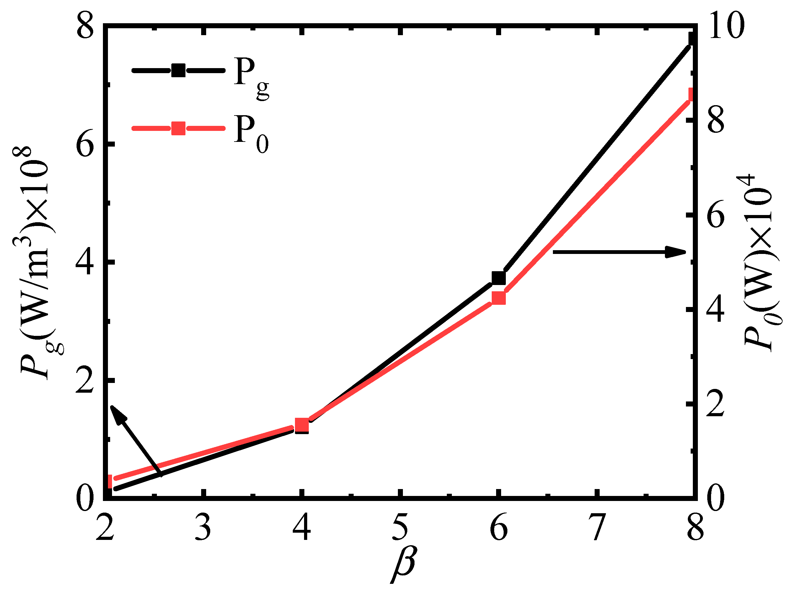
Increasing the Hall effect can significantly enhance the enthalpy extraction rate, while electrical efficiency asymptotically approaches 50%. Consequently, enhancing the Hall effect can substantially improve the overall performance of the power generation channel. This improvement is particularly evident in the initial stages of Hall parameter increase; after which, further increases yield diminishing returns.
Currently, despite extensive theoretical research and experimental work on disk-shaped power generation channels conducted by Japan, the United States, and other countries, practical application still faces considerable challenges due to several key limiting factors. The specific limiting factors are as follows:
(1)
The plasma structure is highly sensitive to external influences, leading to instability and significant, uneven variations in plasma conductivity, which substantially impact the generator performance. These fluctuations can result in reduced efficiency and operational reliability, highlighting the need for advanced stabilization techniques.
(2)
The existing research on disk-shaped channels has primarily focused on relatively small-scale structures. To achieve a competitive mass-to-power ratio of 20 kg/kW for space nuclear magnetohydrodynamic (MHD) power generation systems, the disk-shaped channel must meet stringent high power density requirements. This necessitates innovative design approaches and material advancements to ensure both compactness and efficiency.
(3)
Using inert gases as the working medium necessitates ultra-high-temperature reactors for thermal ionization, presenting significant challenges to the heat resistance and cooling capabilities of the channel and its structural materials. Advanced thermal management systems are essential to mitigate these challenges and maintain optimal operating conditions.
(4)
A strong magnetic field is required for efficient power generation, making the magnet system a critical component. The design and implementation of such a system must balance weight, size, and magnetic field strength to optimize the overall performance.
In conclusion, numerous challenges must be addressed before the disk-shaped power generation channel can be practically implemented. We hope that more researchers will focus on this area to advance the development of space nuclear MHD power generation systems, contributing to deep space exploration.

Author Contributions

Writing—review and editing, software, formal analysis: L.L.; investigation, funding acquisition: G.W.; software: Y.L.; formal analysis: Q.W.; investigation: P.N. All authors have read and agreed to the published version of the manuscript.

Funding

This research was funded by the National Natural Science Foundation of China (No. 52366002).

Institutional Review Board Statement

Not applicable.

Informed Consent Statement

Not applicable.

Data Availability Statement

The original contributions presented in this study are included in the article. Further inquiries can be directed to the corresponding authors.

Conflicts of Interest

The authors declare no conflicts of interest.

References

  1. Tanaka, M.; Okuno, Y. Performance of a Seed-Free Disk Magnetohydrodynamic Generator with Self-Excited Joule Heating in the Nozzle. IEEE Trans. Plasma Sci. 2017, 45, 454–460. [Google Scholar] [CrossRef]
  2. Muraka, T.; Okuno, Y. Experiment and simulation of MHD power generation using convexly divergent channel. In Proceedings of the 42nd AIAA Plasmadynamics and Lasers Conference, Honolulu, HI, USA, 27–30 June 2011. [Google Scholar] [CrossRef]
  3. Muraka, T.; Okuno, Y. Experiments and numerical simulations on high-density magnetohy-drodynamic electrical power generation. J. Appl. Phys. 2008, 104, 063307. [Google Scholar] [CrossRef]
  4. Ichinokiyama, D.; Takayasu, F. Numerical Analysis of Non-equilibrium Disk MHD Generator with Swirl Vanes. In Proceedings of the 14th International Energy Conversion Engineering Conference, Salt Lake City, UT, USA, 25–27 July 2016; p. 4524. [Google Scholar]
  5. Ork, K.; Okuno, Y. Numerical Study of Plasma Behavior and Power Generation Characteristics in a Disk MHD Generator with Xenon-Seeded Neon Gas. IEEE Trans. Plasma Sci. 2023, 51, 1518–1526. [Google Scholar] [CrossRef]
  6. Ork, K.; Masuda, R.; Okuno, Y. Fundamental Experiment and Numerical Simulation of Ne/Xe Plasma Magnetohydrodynamic Electrical Power Generation. J. Propuls. Power 2024, 40, 368–379. [Google Scholar] [CrossRef]
  7. Litchford, R.J.; Harada, N. Multi-MW closed cycle MHD nuclear space power via nonequilibrium He/Xe working plasma. In Proceedings of the Nuclear and Emerging Technologies for Space Meeting, Albuquerque, NM, USA, 7–10 February 2011. [Google Scholar]
  8. Owano, T.G.; Kruger, C.H.; Beddin, R.A. Electron-Ion Three-Body Recombination Coefficient of Argon. AIAA 1991, 1, 75–82. [Google Scholar]
  9. Vasil’eva, R.V.; Erofeev, A.V.; Zuev, A.D. Ionizationally unstable plasma of pure inert gas-working substance in closed-cycle MHD generator. In Proceedings of the 11th International Conference MHD Electrical Power Generation, Beijing, China, 12–16 October 1992; Volume 4, pp. 1199–1205. [Google Scholar]
  10. Ling, W.; Wu, S.; Zhang, Y.; Liu, C.; Meng, H. Numerical simulation on magnetohydrodynamic power generation channel of scramjet. Propuls. Technol. 2024, 45, 261–274. [Google Scholar] [CrossRef]
  11. Liu, F.; Wang, T.; Peng, Y. Faraday type magnetohydrodynamic generator experiment and numerical simulation. Acta Aeronaut. Astronaut. Sin. 2020, 41, 302–311. [Google Scholar] [CrossRef]
  12. Lu, Z.; Zhang, X.; Li, J.; Ma, H. Experimental Study on Inert Gas Magnetohydrodynamic Power Generation by Detonation-Driven. Theor. Appl. Mech. 2023, 55, 1019–1027. [Google Scholar]
  13. Zhu, P.; Peng, A. Research on the Influence of Axial Applied Magnetic Field on the Performance of Disk Magnetohydrodynamic Generator. Power Gener. Technol. 2024, 1–9. [Google Scholar] [CrossRef]
  14. Li, L. Performance Investigation of Plasma Magnetohydrodynamic Power Generation. Master’s Thesis, Nanjing University of Aeronautics and Astronautics, Nanjing, China, 2017. [Google Scholar] [CrossRef]
  15. Tanaka, M.; Murakami, T.; Okuno, Y. Plasma Characteristics and Performance of Magnetohydrodynamic Generator with High-Temperature Inert Gas Plasma. IEEE Trans. Plasma Sci. 2014, 42, 4020–4025. [Google Scholar] [CrossRef]
  16. Tanaka, M.; Aoki, Y.; Zhao, L.; Okuno, Y. Experiments on High-Temperature Xenon Plasma Magnetohydrodynamic Power Generation. IEEE Trans. Plasma Sci. 2016, 44, 1241–1246. [Google Scholar] [CrossRef]
  17. Tanaka, M.; Murakami, T.; Okuno, Y. Plasma Fluid Flow Behavior and Power Generation Characteristics in a High-Temperature Inert Gas Plasma Faraday MHD Generator. Electr. Eng. Jpn. 2016, 194, 46–53. [Google Scholar] [CrossRef]
  18. Harada, N.; Tashiro, T. Influence of Recombination Coefficient on Discharge Structure and Plasma Stability in Closed Cycle MHD Generator with He/Xe Working Gas. In Proceedings of the AIAA Plasmadynamics and Lasers Conference, Orlando, FL, USA, 23–26 June 2003. [Google Scholar]
  19. Harada, N.; Le, C.K.; Tashiro, T. Closed Cycle MHD Generator Using He/Xe Working Plasma. In Proceedings of the Plasmadynamics and Lasers Conference, San Diego, CA, USA, 24–27 June 2013. [Google Scholar]
  20. Harada, N.; Sakamoto, N.; Endo, H. Closed Cycle MHD System Using He/Xe Working Gas. In Proceedings of the AIAA Plasmadynamics and Lasers Conference, Atlanta, GA, USA, 23–25 June 1997. [Google Scholar]
  21. Murakami, T.; Okuno, Y. Simulation and Demonstration of Magnetohydrodynamic Energy Conversion in a High-temperature Inert gas. Phys. Plasmas 2009, 16, 425–429. [Google Scholar] [CrossRef]
Figure 1. The 1/4 section model of the disk-shaped channel.
Magnetochemistry 11 00019 g001
Figure 2. The r-z plane of the disk-shaped channel.
Magnetochemistry 11 00019 g002
Figure 3. Grid division of the power generation channel.
Magnetochemistry 11 00019 g003
Figure 4. Comparison of the electronic temperature.
Magnetochemistry 11 00019 g004
Figure 5. Comparison of the ionization degree.
Magnetochemistry 11 00019 g005
Figure 6. Comparison of the electrical conductivity.
Magnetochemistry 11 00019 g006
Figure 7. Comparison of the static temperature.
Magnetochemistry 11 00019 g007
Figure 8. Comparison of the Mach number.
Magnetochemistry 11 00019 g008
Figure 9. Distribution of static pressure in the r-z plane under different hall parameters obtained by numerical simulation.
Magnetochemistry 11 00019 g009
Figure 10. Distribution of the Mach number in the r-z plane under different Hall parameters obtained by numerical simulation.
Magnetochemistry 11 00019 g010
Figure 11. Distribution of the current lines in the z = 0 plane under different Hall parameter conditions.
Magnetochemistry 11 00019 g011
Figure 12. Contour distribution of the static temperature and current density under the condition of β = 8.0. (a) Contour distribution of the static temperature in the plane of z = 0.003 m. (b) Contour distribution of the current density in the r–z plane near the anode (0.04 m < r < 0.05 m).
Magnetochemistry 11 00019 g012
Figure 13. Radial distribution of the ionization degree and electron number density in the z = 0 m plane. (a) Radial distribution of the ionization degree. (b) Radial distribution of the electron density.
Magnetochemistry 11 00019 g013
Figure 14. Radial distribution of the electrical conductivity and electron-heavy particle collision frequency in the z = 0 m plane under different Hall parameter conditions. (a) Radial distribution of the conductivity. (b) Radial distribution of the electron-heavy particle collision frequency.
Magnetochemistry 11 00019 g014
Figure 15. Changes in the enthalpy extraction rate (ηg) and electrical efficiency (η0) of the power generation channels.
Magnetochemistry 11 00019 g015
Figure 16. Changes in electrical power density and power generation within the channel.
Magnetochemistry 11 00019 g016
Disclaimer/Publisher’s Note: The statements, opinions and data contained in all publications are solely those of the individual author(s) and contributor(s) and not of MDPI and/or the editor(s). MDPI and/or the editor(s) disclaim responsibility for any injury to people or property resulting from any ideas, methods, instructions or products referred to in the content.

