Article

Digital Synthesis of Realistically Clustered Carbon Nanotubes

1
Applied Research Associates Inc., Raleigh, NC 27615-6545, USA
2
Department of Mechanical & Aerospace Engineering, North Carolina State University, Raleigh, NC 27695-7910, USA
*
Author to whom correspondence should be addressed.
Submission received: 24 May 2022 / Revised: 15 June 2022 / Accepted: 18 June 2022 / Published: 22 June 2022
(This article belongs to the Collection Novel Applications of Carbon Nanotube-Based Materials)

Abstract

:
A computational approach for creating realistically structured carbon nanotubes is presented to enable more accurate and impactful multi-scale modeling and simulation techniques for nanotube research. Much of the published literature to date involving computational modeling of carbon nanotubes simplifies their structure as being long and straight, and often existing as isolated individual nanotubes. However, imagery of nanotubes has shown over several decades that nanotubes agglomerate together and exhibit looping and curvature due both to inter- and intra-nanotube attraction. The research presented in this paper leverages multi-scale simulations consisting of a simple bead-spring model for initial nanotube relaxation followed by a differential geometry approach to create an atomic representation of carbon nanotubes, and then finalized with molecular dynamics simulations using the Tersoff potential model for carbon that allows dynamic bonding and cleavage. The result is atomically accurate representations of carbon nanotubes that exist as single nanotubes, or as clusters of multiple nanotubes. The presented approach is demonstrated using (5,5) single-walled carbon nanotubes. The synthesized nanotubes are shown to relax into the curving and looping structures observed in transmission or scanning electron microscopy, but also exhibit nano-scale defects due to buckling, crimping, and twisting that are resolved during the molecular dynamics simulations. These features locally compromise the desired strength characteristics of nanotubes and therefore the presented procedure will enable more accurate modeling and simulation of nanotubes in subsequent research by representing them less as the theoretically straight and independent entities, but as realistically imperfect.

1. Introduction

Since their discovery in the early 1990’s, carbon nanotubes (CNTs) were expected to revolutionize material properties the way carbon fiber had done in the decades prior. Carbon nanotubes are used in myriad applications such as fuel cells [1,2,3], low power electromagnetic device performance [4,5], metal matrix composites [6,7], and even for realizing practical quantum mechanics technological applications [8,9]. The advancement of carbon nanotube manufacturing now allows for controlling the size and chirality of fabricated carbon nanotubes to a greater degree than before. Advances in chirality and orientation-specific growth of CNTs [10,11] have opened the possibility of using tailor-made CNTs with desirable physical characteristics for specific applications. High quality carbon nanotubes are more affordable and practical barriers for regular use of carbon nanotubes are waning. Additional applications for the thermal, electronic, and even optical properties of CNTs continue to emerge.
To further advance the science and applications of CNTs, fundamental research into their properties and behavior is important. Due to the extremely small spatial and temporal scales required to resolve CNT behavior, empirical observation is very difficult, especially for dynamic processes. As multi-scale numerical and computational modeling techniques continue to advance, modeling and simulation is becoming a more viable tool for nanotube research. A great deal of literature exists on the quantum, molecular, and even meso-scale modeling techniques used for various research into nanotubes [12], however, the nanotubes modeled in simulations are often highly simplified or idealized as straight and singular entities [13,14]. This simplification often does not help to understand how nanotubes behave at their true scale. Real carbon nanotubes are almost always agglomerated together, acting under the short-range attraction of Van der Waals forces and real nanotube clusters are almost never entirely straight, exhibiting loops and twists far from the simplified assumptions reported in the literature.
The objective of this paper is to establish enabling tools for generating realistically sized nanotubes and anisotropic nanotube clusters with atomic resolution for exploring new applications using modeling and simulation-based approaches. One targeted area is the use of carbon nanotubes as a reinforcing medium in a metal matrix composite [6,7,15]. While computational resources now exist for molecular dynamics simulations of multi-billions of atoms [16], atomically modeling the whole formation process of nanotubes is still not yet tractable. The time scales required for nucleation events that precipitate nanotube formation are still too great for tenable simulations. This paper presents new modeling techniques for digital synthesis of carbon nanotubes to achieve realistic CNT cluster generation and property observation using contemporary computing resources.

2. Methods and Concepts

2.1. Carbon Nanotube Structure

In order to digitally synthesize carbon nanotubes, it is essential to understand the fundamental geometry of how the nanotubes naturally form. The structure of carbon nanotubes is intuitively related to graphene. Graphene is a two-dimensional sheet of carbon atoms, bonded in a hexagonal lattice. For each carbon atom in the planar sheet, the atoms’ 2s and two of the three 2p orbitals combine into three planar orbitals, 120° apart [17]. These orbitals represent the very strong sp2 bonds which give graphene such a stable two-dimensional structure. If the carbon atoms are spread in the xy plane, the remaining carbon valence electron’s orbital, the 2pz orbital, comes out of the plane in the perpendicular direction to the graphene sheet. This layer of probable electron density provides the relatively weaker bonds between separate sheets of graphene that make up graphite. It is therefore intuitive to imagine that a carbon nanotube is a rolled-up graphene sheet that will tend to focus the interaction potential to act normally to the curved surface of the nanotube. Either van der Waals forces between atoms or transient delocalization of the lingering 2pz orbital from the carbon atoms contributes to how carbon nanotubes attract and repel matter around them, including other nanotubes (inter-CNT attraction) and even different parts of the same nanotube (intra-CNT attraction) [17].
These tendencies to attract or repel are why carbon nanotubes are rarely straight in nature, especially single-walled carbon nanotubes (SWCNTs) that are structurally less rigid than multi-walled carbon nanotubes (MWCNTs). When the SWCNTs are long, the curvature happens over length scales that are significantly longer than the nanotube diameter, so the localized compression and tension that could resist bending is relatively low. Nanotubes, therefore, intertwine into tangled masses. As the entangled nanotube structure grows, the likelihood of attraction-inducing curvature increases, and this results in the large, looping, and anisotropic structures typically observed in carbon nanotube clusters [18,19,20].
The difficulty in characterizing such complicated structures for simulations is that they exhibit anisotropy. It is ordered but not chaotic. Randomly creating strands of nanotubes is therefore unlikely to replicate how the structures come together in the first place. Simulating the natural processes that lead to these structures would incorporate the inherent order to provide more accurate representations, but the required durations of such simulations are unachievable with even massive-scale high performance computing resources. Unfortunately doing so would require simulations of time scales that current atomistic simulations still cannot achieve.

2.2. Multi-Scale Coupling

A methodology is presented in this paper to digitally synthesize a three-dimensional nanotube cluster comprised of atomically resolved nanotubes for the purposes of simulating how the cluster would interact with other materials, in particular molten metals. To the authors’ best knowledge, currently there are no carbon nanotube cluster modeling approaches to create atomically resolved clusters of carbon nanotubes that exhibit realistic anisotropy and localized defect details. The digital synthesis of nanotube clusters consists of several phases, including:
Phase I: Use a random walk and coarse-grained molecular model to create a template that serves as the scaffold upon which atomistic nanotubes will be built.
Phase II: Use differential geometry to refine the coarse-grained representations into fully atomistic carbon nanotubes, forming a cluster.
Phase III: Relax the atomistic nanotube cluster using classical molecular dynamics with an accurate potential model that allows for dynamic bonding and bond-breaking, and inter-and intra-nanotube attraction.
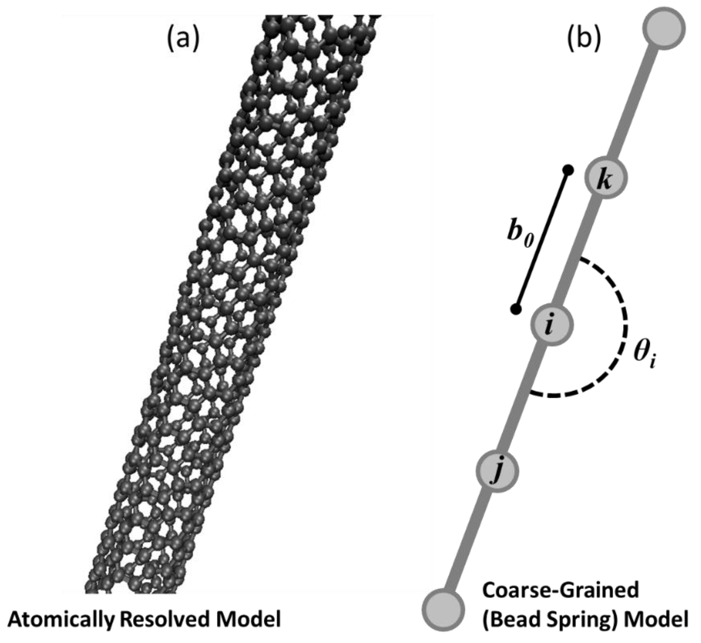
There are two different models for single-walled carbon nanotubes in this work. In Phase I, a Coarse-Grained (CG) bead-spring model [21], referred to as the CG-CNT model, is used as shown in Figure 1a. In Phase I, an atomistic model is used that represents carbon nanotubes in full fidelity as bonded carbon atoms shown in Figure 1a. Despite the difference in scale and fidelity, both nanotube variations model interactions of atoms or coarse-grained beads based on the potential energy for a discrete system as a function of relative atom or bead positions with respect to nearby neighbors. This potential energy approach enables the use of classical molecular dynamics to integrate the trajectories of both representations (beads/nodes or atoms) in time, based on force computations. While the models that govern interactions differ for the two representations of CNTs, the overall approach of simulating them both as systems of atoms in a molecular dynamics simulation is the same. Therefore, both Phase I and Phase III require atomic scale simulations to predict cluster relaxation, but with different computational requirements.
The equations of motion for classical molecular dynamics simulations can be rigorously derived from either Lagrangian mechanics [22] or Hamiltonian dynamics [23]. The system is fully described by atomic coordinates and atomic momenta, collectively referred to as the system’s phase space. This dynamic system is given thermodynamic meaning through statistical mechanics where ensemble averages of phase space are related to macroscopic thermodynamic variables. In this paper both the micro-canonical ensemble (constant number of atoms, constant volume, constant energy, NVE) and the canonical ensemble (constant number of atoms, constant volume, and constant temperature, NVT) are used. Among the differences of the two are that the NVE ensemble holds energy constant, treating the system as thermodynamically conserved. The NVT ensemble allows the system to interact with a thermal reservoir where energy can be exchanged. We defer the formal derivations to reference texts [22,23] and define here the governing equations of motion for the molecular dynamics system as in [22] and shown in Equation (1) for a single atom i, where the vector r ¯ i denotes spatial coordinates of the atom, m i is mass of the atom, V i represents potential energy of the atom relative to its neighbors that will be defined below, γ is a damping coefficient used only for the canonical ensemble simulations and otherwise set to zero, and u ¯ i is the instantaneous velocity of the atom.
m i 2 r ¯ i t 2 = r i ¯   V i γ u ¯ i
Potential energy for a given atom is defined following [22] as shown in Equation (2) where V q denotes potential energy functions involving 1, 2, 3, …, q particles at positions r q in three-dimensional space relative to each ith atom of the system.
V i = i V 1 ( r i ) + i j > i V 2 ( r i , r j ) + i j > i k > j V 3 ( r i , r j , r k ) +
Appropriate selection of the potential energy functions is of paramount importance for a molecular dynamics simulation in either the micro-canonical or canonical ensemble. The forms of these functions used in this paper are detailed in subsequent sections and vary between Phase I and Phase III of the methodology presented in this paper. Despite the different choices for the potential energy functions, the open source Large-scale Atomic/Molecular Massively Parallel Simulator (LAMMPS) code [24] is used for both the CG-CNT relaxation (Phase I) as well as the fully atomistic simulations (Phase III) in this work.
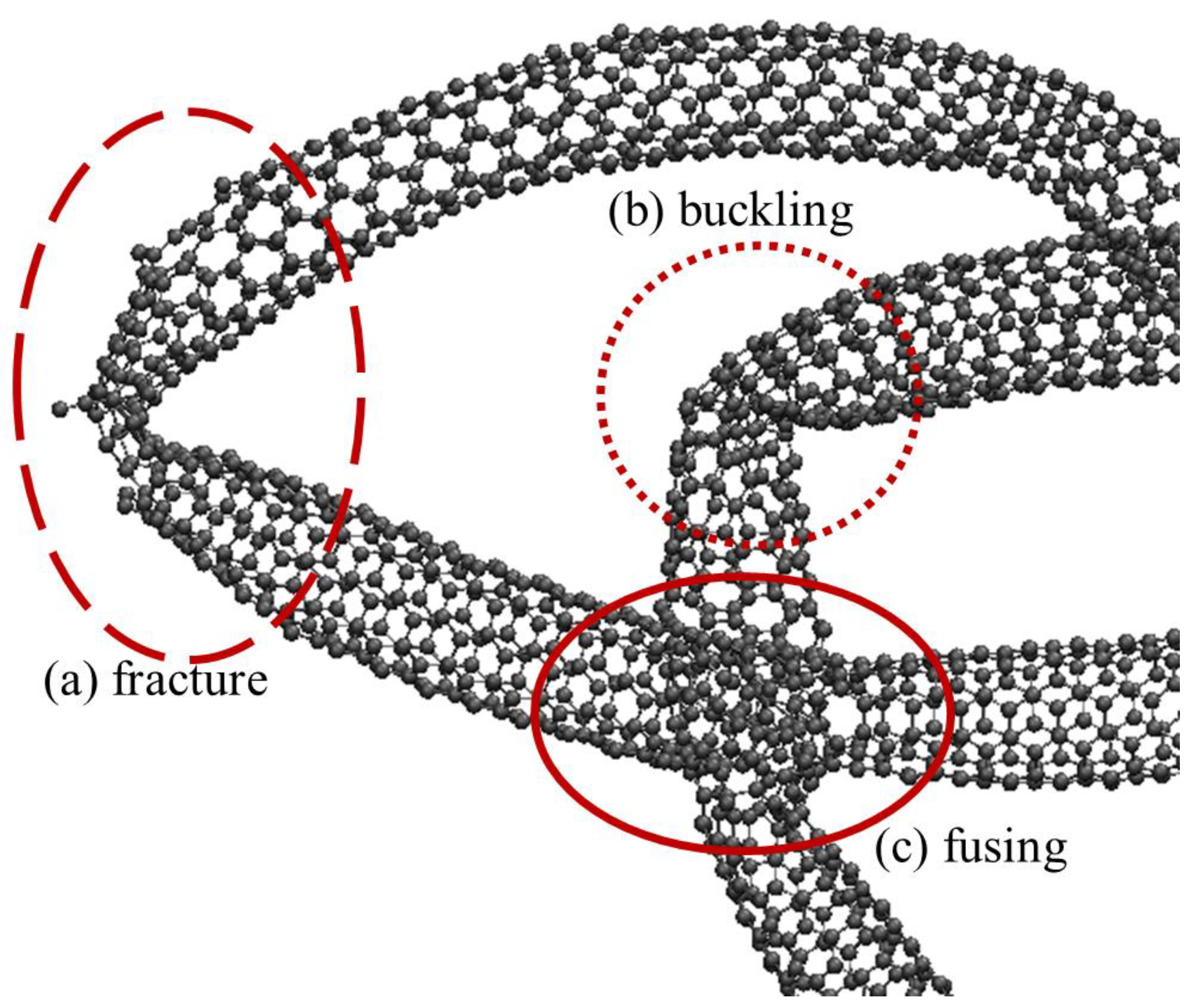
The CG-CNT model is used only in Phase I for creating initial topological scaffolds for the creation of realistic carbon nanotubes and clusters. The CG-CNT model enables large conformational relaxation of fabricated clusters, but does not correctly model CNT defects from buckling, twisting, or bending. The atomistic carbon interactions that are used for all stages of this research beyond initial CNT synthesis are modeled using the Tersoff empirical bond order model for atomistic carbon interactions [25,26], detailed in Phase III.

2.3. Phase Ia: Random Walk to Generate an Initial CG-CNT

The initial phase of creating a carbon nanotube or nanotube cluster consists of seeding N individual points in space at random or pseudo-random locations in a spatial domain, where N is the number of desired nanotubes. Consistent random number seeds were used in this work to obtain pseudo-random locations to ensure repeatable carbon nanotube cluster realizations, but truly random numbers could be used the same way in this methodology. These pseudo-random individual points serve as the beginning node of discrete space curves that will eventually form nanotube filaments constructed using the CG-CNT methodology. The curves are built in piecewise increments where a new node is placed a known distance from the previous, but in a randomized direction. Essentially, this is akin to creating N random walks. The discretization, or the length of each discrete element of the curve, is a CG-CNT model parameter that is more fully defined in the next section.

2.4. Phase Ib: Coarse-Grained Carbon Nanotube Modeling

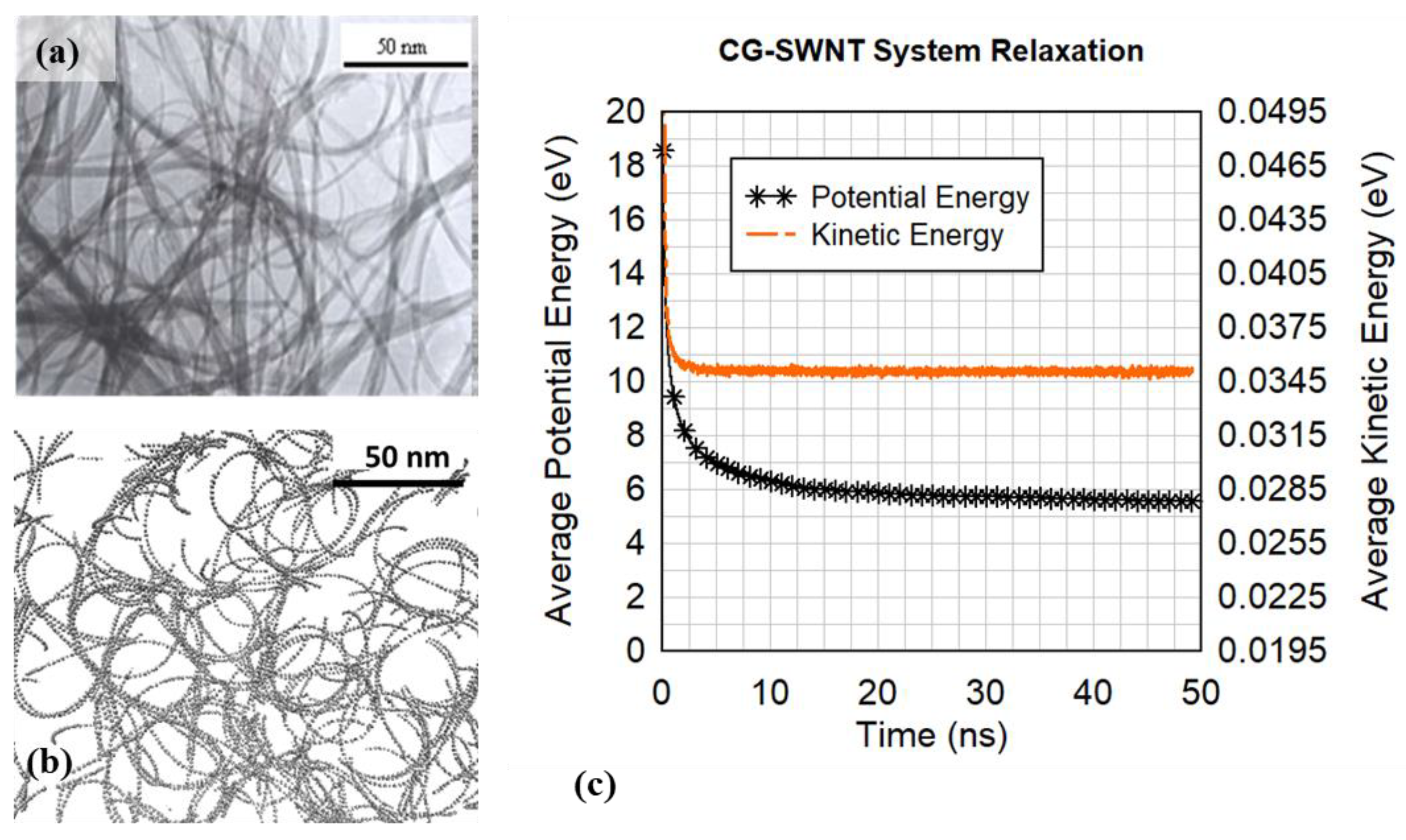
There is no accounting for physically preferential orientations of the discrete curve elements generated during the random walk, but the intended effect of these curves is to serve as something resembling a relatively rigid carbon nanotube. The intuition is therefore that the very tangled and cramped random walk realizations will want to stretch out, and the CG-CNT methodology is employed to govern that relaxation. The relaxation is a process to allow the atoms to settle into equilibrium positions that minimize the system’s potential energy.
There is considerable work in the literature on modeling single- and double-walled carbon nanotubes as coarse-grained filaments, attempting to replicate how clusters of carbon nanotubes exist in nature as individual elements and as interacting structures [21,27,28,29]. These methods attempt to incorporate more realistic physical modeling of the natural nanotube clustering, but still lack the effects of nanotube fracture, crimping, and torsion in such relatively larger structures. The model used in this paper is based on [21] where the CG-CNT model coarsens a single-walled carbon nanotube into a filament discretized into evenly spaced beads or nodes, as illustrated in Figure 1.
The beads are subject to inter- and intra-bead attraction, bending, and bonding forces that are deliberately designed to be analogous with conventional molecular dynamics potentials. Referring to Figure 1b for graphical depictions of parameters defined in the following equations, three terms contribute to an overall potential energy relationship for any bead i as a function of its explicitly bonded neighbors (j, and k) and any nearby beads within a cutoff radius as shown in Equation (3).
V i = B o n d s V ( r i ,   r ) s t r e t c h i n g + V ( r i ,   r j , r k ) b e n d i n g + m     j ,   k V ( r i ,   r m ) V a n   d e r   W a a l s
Stretching between bonded neighbors is modeled using a harmonic potential shown in Equation (4) where an equilibrium distance between a bead and its neighbors is defined as b 0 and k s is a defined parameter that dictates the magnitude of the potential energy for atomic positions that are not at the equilibrium distance. In this paper, r ¯ i l denotes the non-normalized distance in Cartesian space from coordinate r ¯ i to coordinate r ¯ .
V ( r i ,   r ) s t r e t c h i n g = 1 2 k s ( r ¯ i l b 0 ) 2
Each bead except the first and final bead of a coarse-grained carbon nanotube model experience this stretching potential for two neighbors, in the illustration in Figure 1b this would mean that bead i experiences stretching contributions to the net potential energy from its bond with bead j and bead k.
The bending function is a three-body potential, measured about a bead and its two bonded neighbors. An angle defined as θ i in Figure 1b is computed using the Law of Cosines and the coordinates of bead i and its two bonded neighbors. Displacement of that computed angle θ i from an equilibrium angle θ 0 contributes to a harmonic potential energy function weighted by a bending stiffness coefficient, k θ as shown in Equation (5).
V ( r i , r j , r k ) b e n d i n g = 1 2 k θ ( c o s 1 (   r ¯ i j + r ¯ i k r ¯ j k 2 · r ¯ i j   ·   r ¯ i k ) θ 0 ) 2
The angle term is only computed for beads with two bonded neighbors.
The final term in the coarse-grained model potential energy function shown in Equation (3) is a pair-wise potential with any non-bonded beads within a cutoff radius. The distance between a bead i and any non-bonded neighbor bead m is computed using a Lennard-Jones 12-6 potential as shown in Equation (6) where ε and σ are the potential energy well depth and equilibrium distance respectively.
V ( r i ,   r m ) V a n   d e r   W a a l s = 4 ε [ ( σ r ¯ i m ) 12 ( σ r ¯ i m ) 6 ]
For computational efficiency, the pair-wise interactions modeled using Equation (6) are modeled only for as many neighbors as fall within a certain radial distance from a bead, a distance referred to as the Lennard-Jones (LJ) cutoff distance. The contribution of this term rapidly diminishes for atomic distances on the order of two or three times the equilibrium distance σ, so truncating the number of neighbors based on a cutoff radius is a widely accepted procedure for this type of a potential model. The pair-wise potential accounts for inter- and intra-nanotube attraction and is the mechanism through which carbon nanotubes tend to agglomerate into clusters and exhibit looping structures.
The free parameters of the bead-spring model defined in Equations (4)–(6) are determined so that the coarse-grained model will match the tensile strength, bending modulus, and persistence length of a (5,5) single-walled carbon nanotube (Figure 1a). The parameters used in this paper are shown in Table 1 and consistent with those reported in [21,30,31].
Molecular dynamics simulations using the potential model described in this section relax the previously disordered and energetically unfavorable random walk clusters into filaments that physically resemble carbon nanotubes and nanotube clusters more realistically.
Ensuring the coarse-grained model replicates atomically resolved carbon nanotube properties helps improve the physical accuracy and fidelity of the random walk realizations as they relax into a cluster, improving the behavior of the fully resolved atomic nanotube cluster relaxation in Phase III.

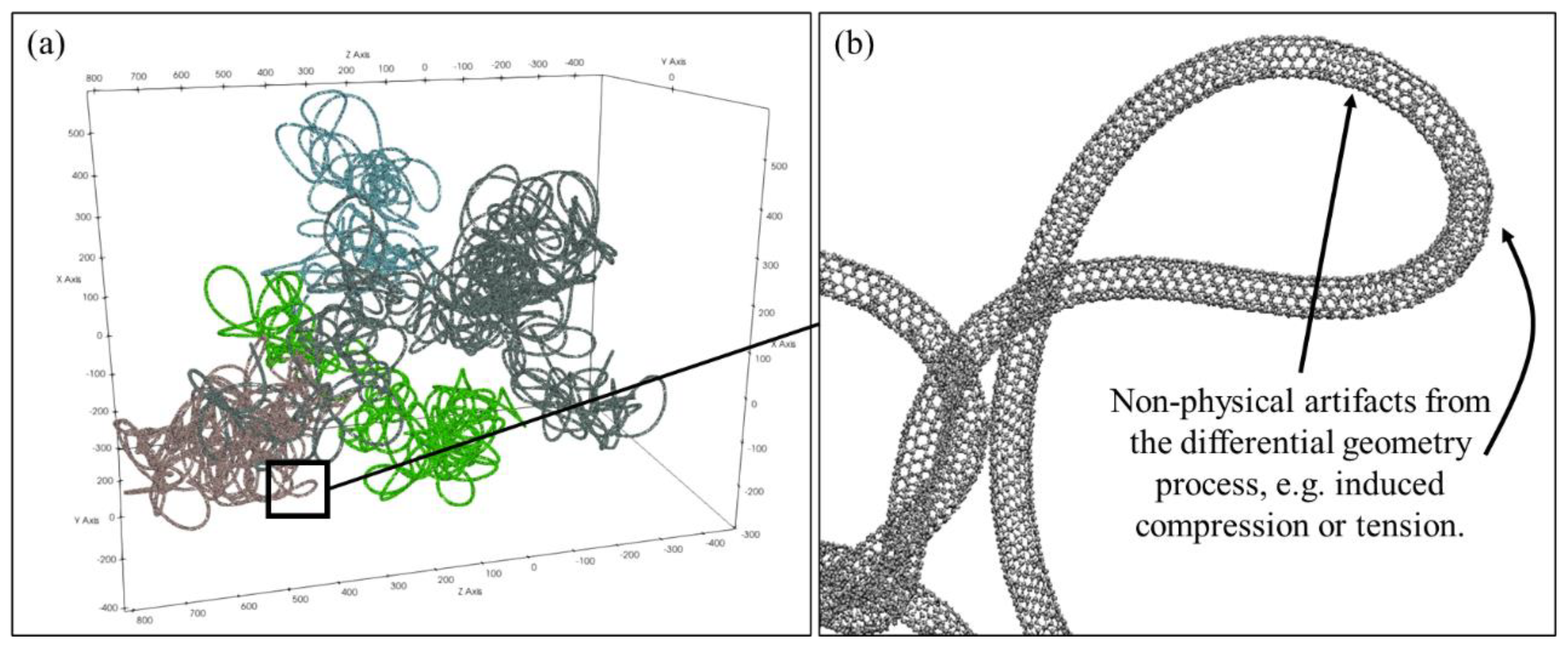
2.5. Phase II: Differential Geometry

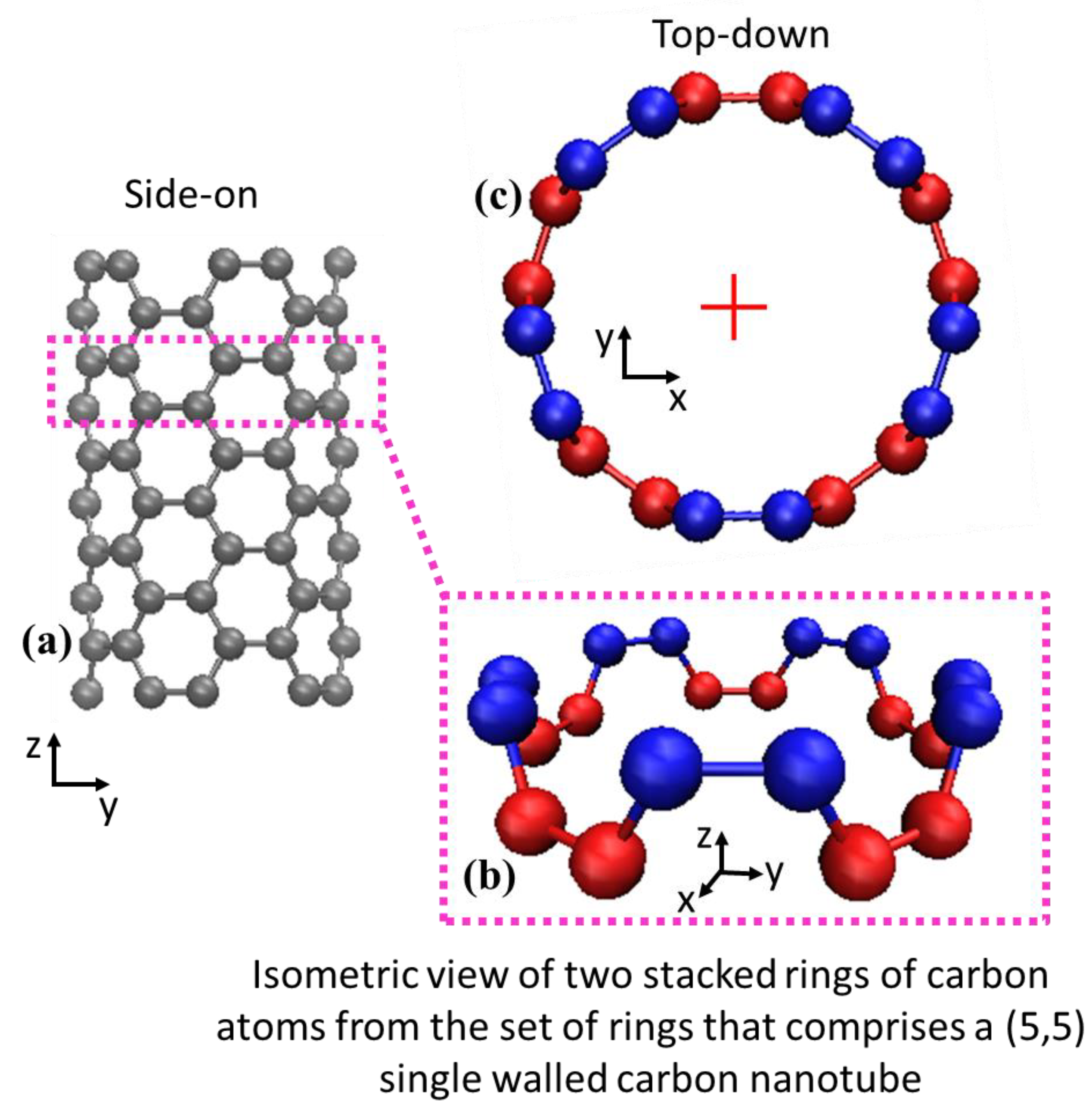
This phase represents a bridge to convert the coarse-grained approximations of nanotubes as filaments into fully atomic carbon nanotubes. The coarse-grained nanotubes function as a central axis upon which carbon atoms are accurately positioned. The process can be envisioned as incrementally building an atomic carbon nanotube as a series of concentric atomic rings stacked atop each other. In the limit of a perfectly straight carbon nanotube (Figure 1a) the procedure is very simple. Beginning at the base of a bead-spring filament, an initial ring of carbon atoms is placed along the filament’s longitudinal axis, where the carbon atoms are arranged at the known circumferential position for the (5,5) SWNT (e.g., the red atoms in Figure 2b,c). Another ring is then placed at the known step size δ along the filament length, rotated by θ about the axis perpendicular to the plane of the prior ring (e.g., the blue atoms in Figure 2b,c). Parameters δ and θ used in this work are shown in Table 2 for (5,5) single-walled carbon nanotubes, but adaptation to other arm-chair carbon nanotubes is straightforward. For example, the prevalent (10,10) single-walled carbon nanotube would be built the same way as described here, except for changes to the single carbon ring commensurate with the additional carbon atoms and increased radius, and different δ and θ parameters.
An example of a straight carbon nanotube is depicted in Figure 2a and examples of two levels of stacked atomic rings are shown by red and blue layers in Figure 2b,c.
For a straight nanotube, repeated operations of rotating and stacking of atomic rings of carbon would incrementally build a nanotube and are trivial to execute. Real carbon nanotubes are almost never straight however, which complicates the rotation operation of the stacking procedure. The central axis normally exhibits curvature and so an additional rotation must take place for the plane of the atomic ring, but it cannot be arbitrary or else the nanotube lattice will not be maintained. A differential geometry approach to curve framing is used called the Parallel Transport frame [32,33]. This approach provides mathematical formalism to create an initial nanotube structure that orients the discrete atomic rings correctly along the axis of the curved bead-spring filament. It is similar in nature to Frenet-Serret frames [34] that define planes along a space curve, but is more suitable for the present research because the calculations of Frenet-Serret frames requires the second order derivative of the curve which does not exist for straight lines and manifests in abrupt orientation changes when the second derivative approaches and crosses local minima and maxima. Carbon nanotubes in this research exist in both of those cases and so Frenet-Serret frames are not ideal. Janakiev provides a very useful description and implementation examples of parallel transport frames in [33] that complements the original work by Hanson and Ma [
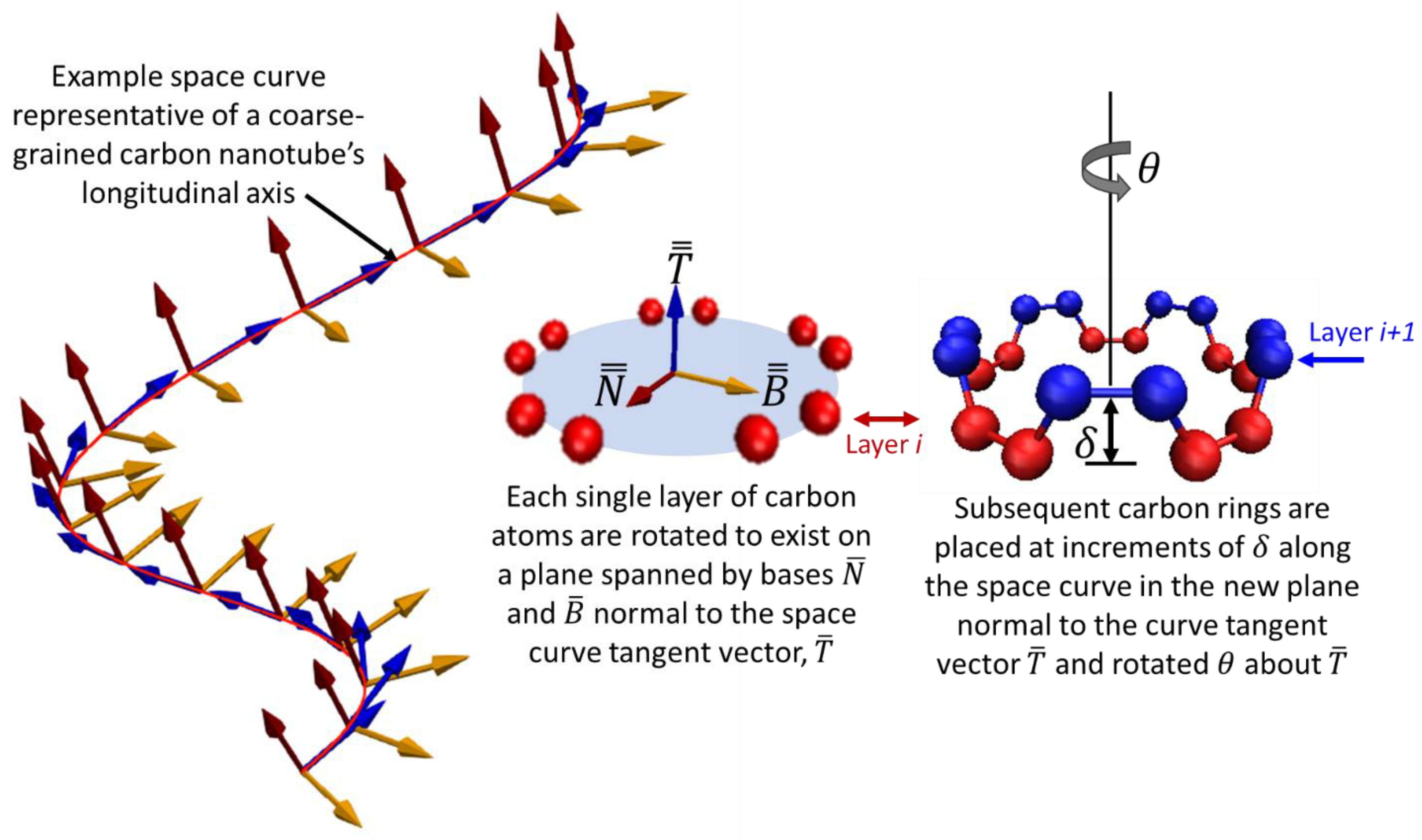
32] and differentiates it from Frenet-Serret. The concept is illustrated for a generic three-dimensional space curve in Figure 3 where the red line is a curve defined in three-dimensions, and the parallel transport frames approach is illustrated at finite increments along the curve where local frames are shown to remain consistent.
Consider a discrete curve in space illustrated in Figure 3, composed of discrete points represented by the matrix S = which is an m × 3 matrix where m is the number of discrete points that comprise the curve, each point being in three dimensions. The parallel transport of the frames begins with the first derivative computed with respect to the spatial dimensions of the space to obtain the curve’s tangent vectors, T = as shown in Equation (7). These are then normalized and are shown in Figure 3 as the set of blue vectors.
T = = S =
The set of normal vectors to the tangents, B = in Figure 3 are then computed using the normalized cross-product between two successive tangent vectors using Equation (8).
B = = { t ¯ i + 1 × t ¯ i t ¯ i + 1 × t ¯ i } i   f o r   i = 1   t o   m
A final basis vector set N = is then computed from the cross products of sets B = and T = .
Each discrete frame spanned by basis vectors N ¯ and B ¯ from sets N = and B = shown in Figure 3 represent the plane orientation of the carbon atoms unit cell, pictured as the red or blue atoms in Figure 2b,c. The central axis of the coarse-grained nanotube filament is the red curve, with piecewise orientation vectors denoted by the blue vectors in Figure 3.
At each increment δ along the central axis, the carbon atom ring is rotated θ about the prior increment’s blue vector and then rotated again to coincide with the plane defined by the red and yellow vectors that are each orthogonal to the tangential vector (blue).
Although the methodology presented here was based on parallel transport frames reported in the literature, the application of it to create realistic carbon nanotubes is new.

2.6. Phase III: Atomistic Carbon Nanotube Modeling

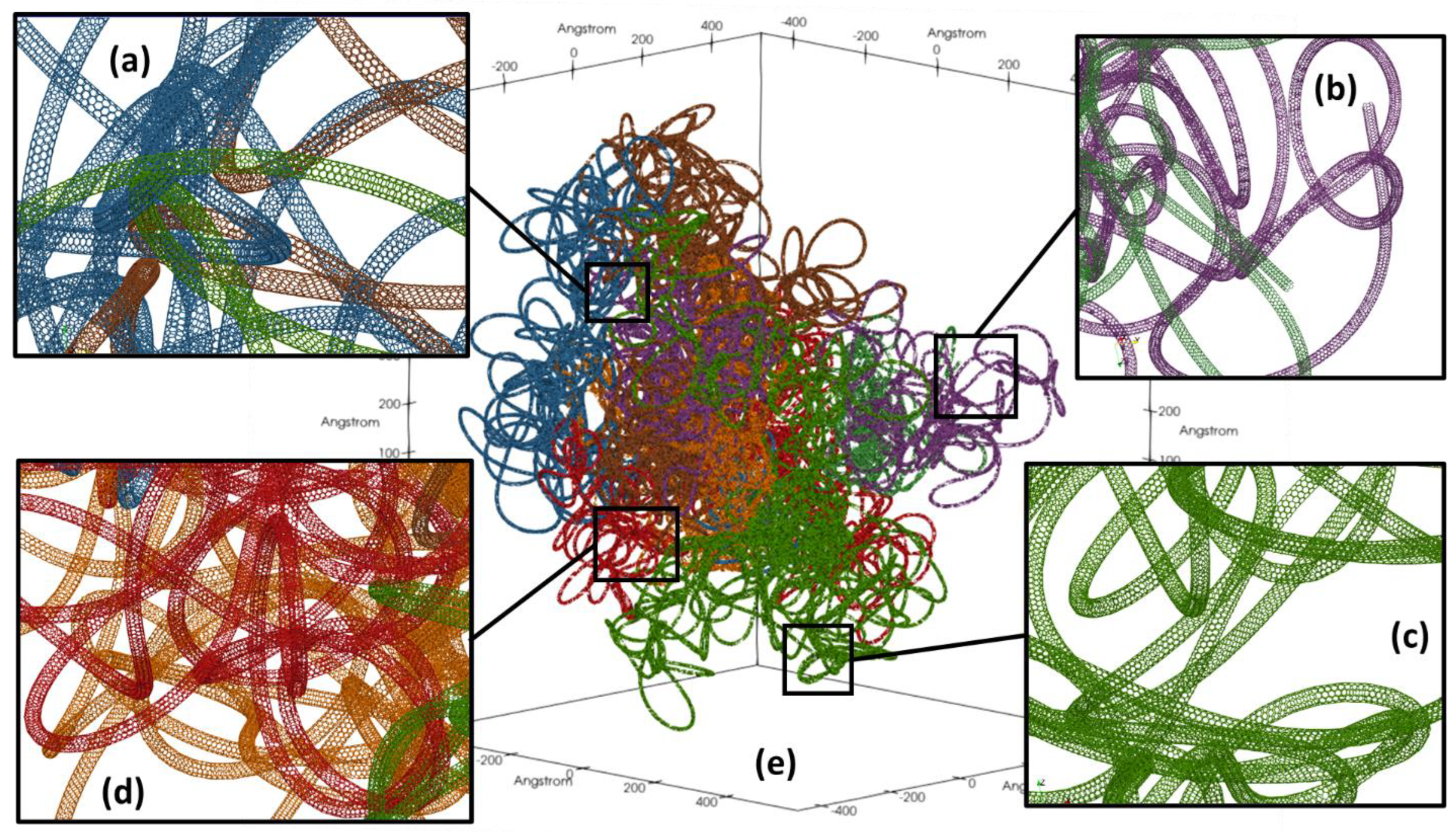
Phase I creates individual filaments of realistically curved, looping, and agglomerated carbon nanotube surrogates to serve as a central axis for an atomic representation of a carbon nanotube. Phase II orients the carbon rings along all of the filaments to create atomic carbon nanotubes in the cluster. Phase III then models the carbon atoms individually to allow the whole carbon nanotube cluster to behave as a complex system with atomic resolution.
There are a variety of classical molecular dynamics potentials used for atomistic modeling of carbon structures, but for this work the Tersoff empirical bond order model is chosen [26] with optimized carbon–carbon model parameters defined by Lindsay and Broido [25]. Practical experience using other dynamic potential models including ReaxFF and AI-REBO have informed the conclusion that the Tersoff potential provides the best balance of requisite fidelity of carbon nanotube response and computational efficiency as befits the overall problem at hand. Since the Tersoff potential model includes dynamic bonding and bond-breaking commensurate with nanotube deformation, it has enough physical fidelity for the present application while also being stable and efficient for the number of carbon–carbon interactions modeled in this work. The Tersoff potential model is introduced here but the reader is referred to [26] for greater detail. The general potential energy functional form Equation (2) is defined for the Tersoff model as V i in Equation (9) which is the summation of pairwise bond energies Vij between atoms i and j, shown respectively in Equations (9) and (10) which includes both attractive Equation (11) and repulsive Equation (12) potential energy terms, as well as a smoothing function Equation (13) that implements a cut-off for interactions that become vanishingly small with increased separations.
V i = 1 2 i j V i j ( r i ,   r j )
V i j ( r i ,   r j ) = f C ( r ¯ i j ) [ a i j · f R ( r ¯ i j ) + b i j · f A ( r ¯ i j ) ]
f A ( r ) = B · e λ 2 · r
f R ( r ) = A · e λ 1 · r
f C ( r ) = { 1 , r < R D 1 2 1 2 s i n ( π 2 · ( r R ) D ) ,   R D < r < R + D 0 ,   r > R + D  
The coefficients A, B, λ 1 , λ 2 , R, and D are model parameters defined for the system of interest in [25], and the a i j and b i j terms in Equation (10) are defined in Equation (14) through Equation (18) from [26] with model coefficients c, d,   λ 3 , α, β, and n also defined in [25].
a i j = ( 1 + α n · η i j n ) 1 2 n
η i j = k i , j f C ( r i k ) · e λ 3 3 ( r i j r i k ) 3
b i j = ( 1 + β n · ξ i j n ) 1 2 n
ξ i j = k i , j f C ( r i k ) · g ( θ i j k ) · e λ 3 3 ( r i j r i k ) 3
g ( θ ) = 1 + c 2 d 2 c 2 [ d 2 + ( h c o s ( θ ) ) 2 ]
The Tersoff potential is very widely used for atomic carbon–carbon interactions and the model parameters, and the coefficients used in Equation (10) through Equation (18) do not vary based on a particular application of the methodology. Since the model predicts carbon–carbon interactions, the configuration being carbon nanotubes, graphene, graphite, or amorphous carbon does not matter, just that the Tersoff potential model predicts physical bonding and orientation of individual carbon atoms. The present work uses model coefficients defined using the parameterization for carbon–carbon interactions from [25], and as implemented in LAMMPS [24]. The Tersoff potential is used for all atomically resolved motion of the carbon nanotube cluster in Phase III of the presented methodology when relaxing the carbon nanotube cluster to a more energetically favorable configuration.

3. Results

An entangled nanotube cluster has been created to demonstrate the algorithm described in Section 2, consisting of 10 individual nanotubes with lengths sampled from measurements published by Carbon Solutions Inc. [35] for typical CNT clusters as manufactured at their facility. The procedure results in 2,072,310 carbon atoms that form coherent carbon nanotube structures that converged to an equilibrium potential energy.

3.1. Coarse-Grained Cluster Generation

The process to generate a coarse-grained carbon nanotube cluster begins with N random walks, each of which generates a single filament, where the step length is dictated by the coarse-grained model equilibrium bead distance defined to be 10 in Table 1. This process repeats successively for the desired number of carbon nanotubes in a cluster as described in Phase Ia and Phase Ib in Section 2.2. Different realizations of 10 coarse-grained carbon nanotubes are shown in Figure 4 where the individual and unrelaxed carbon nanotube filaments are differentiated by color.
We can closely examine how different filaments are entangled within the cluster. Severe and unphysical kinks are prevalent, as shown in Figure 4b. The relaxation of the initial filaments into a realistic cluster is not a static process and the system potential energy and kinetic energy were monitored during micro-canonical (NVE) ensemble simulations of 49 nanoseconds. Convergence in the kinetic and potential energy indicate that the system reaches equilibrium as shown in Figure 5c. Figure 5b is a slice of an image of the coarse-grained cluster of the simulation result, compared with the Transmission Electron Microscopy (TEM) image of a CNT cluster from Liu et al. [19] shown in Figure 5a.

3.2. Differential Geometry with Molecular Dynamics Relaxation

Each of the individual coarse-grained carbon nanotubes within the cluster that were relaxed for 49.1 ns of simulation time now serve as space curves for the differential geometry phase of the model to create fully atomic carbon nanotubes. Four of the 10 fully atomic carbon nanotubes are shown in Figure 6a prior to any further molecular dynamics relaxation (the other six CNTs are not shown simply for better clarity). A close-up view of one loop is shown in Figure 6b. From this close-up image, we observe that some sections of the nanotube are either compressed or stretched, demonstrated by the narrowed or enlarged spacing with neighboring atomic rings. These compressed or stretched sections indicate that some atomic positions are close to a realistic configuration but not exact.
The final stage of generating the CNT cluster is to relax the fully articulated atomistic nanotubes to remove those compressed or stretched sections. A series of dampened molecular dynamics simulations are used to relax the atoms, this time using the Tersoff potential to account for any induced defects or maladies resulting naturally by the nanotube’s atomic motion. The damping force applied to the atoms alters the system energy, and so the system is no longer guaranteed to remain within the micro-canonical ensemble. Instead, the system evolves in the canonical ensemble (NVT) where a Langevin force is added to the atoms that acts to slow atomic motion proportional to the atom’s velocity [24,36]. In the present work, the damping is imposed using the fix viscous command in LAMMPS, meaning that the Brownian motion term of the Langevin force is zero and only the damping term remains as shown in Equation (1). The imposed viscous damping was decreased over successive simulations. The overall relaxation occurred over 3.5 nanoseconds of simulated duration, divided into the stages described in Table 3.
The durations shown in Table 3 were derived from monitoring the system’s total energy, and the values presented represent durations at which point the system’s total energy had converged and the atomic positions were no longer moving appreciably. At the end of the five stages, the last of which was undamped, a relaxed and atomically resolved 100 nm cluster has been created as shown in Figure 7e, where insets (a–d) are used to show greater detail of the individual nanotubes exhibiting curvature and entanglement.
The transient kinetic and potential energy over the 3.5 ns duration of the five stages described in Table 3 is shown in Figure 8. The relaxation of the whole system is clearly shown by both the kinetic energy (red curve with diamond markers) and the time derivative of the system’s average potential energy (blue curve with no markers) stabilizing at zero on their respective axes, indicating a converged minimum energy state of the system.

4. Discussion

Some of the nanotubes in the generated cluster exhibited defects, such as those shown in Figure 9, that have also been observed in real nanotube clusters from TEM imagery [37,38,39]. The TEM observations corroborate that kinks and fusing exist, but they do not quantify the effect these defects have on structural integrity of the nanotubes, nor do they have the resolution to show individual atoms as shown in Figure 9. However, copious publications exist that investigate carbon nanotube structural integrity, stiffness, tensile strength using computational modeling (e.g., [12] among others), including the Tersoff potential formulation used in this paper as well as advanced quantum mechanics models like Density Functional Theory. This comprehensive body of work indicates that the failure mechanisms shown in Figure 9 are expected responses to the types of features observed in TEM imagery, however as mentioned previously in this paper, most computational studies of carbon nanotubes in the literature consider only highly simplified scenarios or idealized carbon nanotubes. The importance of this presented work is highlighted as being able to predict the realistic clustering features of carbon nanotubes as observed in TEM images, but with atomic resolution that enables computational modeling of nanotube structural defects as they likely exist as fabricated or treated in practice. This is especially consequential for designing and optimizing processes to create composite materials where carbon nanotubes are a reinforcing medium in the composite material. Localized areas of compromised structural integrity will negatively impact the efficacy of nanotube reinforcement in the composite materials and this research provides more realistic characterizations for carbon nanotubes to inform those designs.
This research will be used in conjunction with prior carbon nanotube modeling work [15] to further explore the hydrodynamic effects that molten copper exerts on agglomerated carbon nanotubes, where defects as shown in Figure 9 may be of consequence.
The digital synthesis presented in this paper does not produce rope-like structures where individual SWNTs longitudinally attract under van der Waals forces. Such rope-like features have been observed in TEM imagery like that of Figure 5 or as reported in [20]. It is likely that by controlling the simulation parameters to change the nearest-neighbor search cutoff distance could lead to the rope-like structure. Although this topic is beyond the scope of this paper, it is important to investigate if the presented methodology can be expanded to synthesize other SWCNT cluster structures.

5. Conclusions

A procedure for creating realistic simulated carbon nanotube clusters with atomic resolution has been presented and demonstrated for a cluster of 10 carbon nanotubes. This work significantly improves the fidelity and realism of simulated carbon nanotube clusters, without significant increases in computational complexity or resources. The novelty of this paper is in the simplifications regarding the temporal domain to achieve carbon nanotube structures that qualitatively match electron microscopy images while at the same time preserving the spatial fidelity of atomistic simulations. The unique contributions that enabled these results include the application of a parallel frame transport methodology to a coarse-grained relaxation of random carbon nanotube realizations to create atomically resolved carbon nanotubes. The work presented in this paper is limited to single-walled (5,5) carbon nanotubes but is adaptable to other chiralities and multi-walled carbon nanotubes with relatively minor changes.
The applications for this research include better understanding the ramifications of realistic nanotubes clusters for thermal, electronic, or optical properties, for greater characterization of how clusters affect strength transfer between matrix material and nanotube inclusions in composite materials, or better understanding the hydrodynamics and molecular mixing of nanotubes. This presented work will inform future research where additional physical phenomena like wetting and rheology become increasingly important, such as understanding inhalation dynamics of nanotube clusters and whether their deposition in human airways is dangerous, or how compromised structural integrity of carbon nanotube clusters affect composite materials when carbon nanotubes are the participating reinforcing medium.

Author Contributions

Conceptualization, B.T.S. and J.F.T.; methodology, B.T.S.; software, B.T.S.; validation, B.T.S.; formal analysis, B.T.S. and J.F.T.; investigation, B.T.S. and J.F.T.; resources, B.T.S. and J.F.T.; data curation, B.T.S.; writing—original draft preparation, B.T.S.; writing—review and editing, B.S and J.F.T.; visualization, B.T.S.; supervision, J.F.T.; project administration, B.T.S. and J.F.T.; funding acquisition, B.T.S. and J.F.T. All authors have read and agreed to the published version of the manuscript.

Funding

This research received no external funding.

Institutional Review Board Statement

Not applicable.

Data Availability Statement

Not applicable.

Acknowledgments

The authors would like to acknowledge Applied Research Associates Inc., and North Carolina State University for use of the Henry2 HPC cluster for the simulations performed.

Conflicts of Interest

The authors declare no conflict of interest.

References

  1. Kumar, M.K.; Ramaprabhu, S. Palladium dispersed multiwalled carbon nanotube based hydrogen sensor for fuel cell applications. Int. J. Hydrogen Energy 2007, 32, 2518–2526. [Google Scholar]
  2. Li, W.; Wang, X.; Chen, Z.; Waje, M.; Yan, Y. Carbon nanotube film by filtration as cathode catalyst support for proton-exchange membrane fuel cell. Langmuir 2005, 21, 9386–9389. [Google Scholar] [CrossRef] [PubMed]
  3. Wang, X.; Li, W.; Chen, Z.; Waje, M.; Yan, Y. Durability investigation of carbon nanotube as catalyst support for proton exchange membrane fuel cell. J. Power Sources 2006, 158, 154–159. [Google Scholar] [CrossRef]
  4. Xiong, F.; Liao, A.D.; Estrada, D.; Pop, E. Low-power switching of phase-change materials with carbon nanotube electrodes. Science 2011, 332, 568–570. [Google Scholar] [CrossRef] [Green Version]
  5. Zhong, D.; Zhang, Z.; Ding, L.; Han, J.; Xiao, M.; Si, J.; Xu, L.; Qiu, C.; Peng, L.-M. Gigahertz integrated circuits based on carbon nanotube films. Nat. Electron. 2018, 1, 40–45. [Google Scholar] [CrossRef]
  6. Tu, J.F.; Rajule, N.; Molian, P.; Liu, Y. Laser synthesis of a copper–single-walled carbon nanotube nanocomposite via molecular-level mixing and non-equilibrium solidification. J. Phys. D Appl. Phys. 2016, 49, 495301. [Google Scholar] [CrossRef]
  7. Tu, J.F.; Rajule, N.; Mun, S.D. Laser Spot Welding and Electric Contact Points Using Copper/Single-Walled Carbon Nanotube Nanocomposite Synthesized by Laser Surface Implanting. J. Compos. Sci. 2021, 5, 87. [Google Scholar] [CrossRef]
  8. Pistolesi, F.; Cleland, A.N.; Bachtold, A. Proposal for a nanomechanical qubit. Phys. Rev. X 2021, 11, 031027. [Google Scholar] [CrossRef]
  9. Rips, S.; Hartmann, M.J. Quantum information processing with nanomechanical qubits. Phys. Rev. Lett. 2013, 110, 120503. [Google Scholar] [CrossRef] [Green Version]
  10. Liu, B.; Liu, J.; Tu, X.; Zhang, J.; Zheng, M.; Zhou, C. Chirality-Dependent Vapor-Phase Epitaxial Growth and Termination of Single-Wall Carbon Nanotubes. Nano Lett. 2013, 13, 4416–4421. [Google Scholar] [CrossRef]
  11. Stano, K.L.; Chapla, R.; Carroll, M.; Nowak, J.; McCord, M.; Bradford, P.D. Copper-Encapsulated Vertically Aligned Carbon Nanotube Arrays. ACS Appl. Mater. Interfaces 2013, 5, 10774–10781. [Google Scholar] [CrossRef] [PubMed]
  12. Qiu, C.; Su, Y.; Yang, J.; Chen, B.; Ouyang, Q.; Zhang, D. Structural modelling and Mechanical Behaviors of Graphene/Carbon Nanotubes Reinforced Metal Matrix Composites via Atomic-scale Simulations: A Review. Compos. Part C Open Access 2021, 4, 100120. [Google Scholar] [CrossRef]
  13. Long, Y.; Śliwińska-Bartkowiak, M.; Drozdowski, H.; Kempiński, M.; Phillips, K.A.; Palmer, J.C.; Gubbins, K.E. High pressure effect in nanoporous carbon materials: Effects of pore geometry. Colloids Surf. A Physicochem. Eng. Asp. 2013, 437, 33–41. [Google Scholar] [CrossRef]
  14. Tang, J.; Wang, X.; Zhang, J.; Wang, J.; Yin, W.; Li, D.S.; Wu, T. A chalcogenide-cluster-based semiconducting nanotube array with oriented photoconductive behavior. Nat. Commun. 2021, 12, 4275. [Google Scholar] [CrossRef] [PubMed]
  15. Susi, B.T.; Tu, J.F. Molecular dynamics simulations of the wetting behavior of carbon nanotubes in liquid copper. Comput. Fluids 2018, 172, 19–28. [Google Scholar] [CrossRef]
  16. Barreales, G.N.; Novalbos, M.; Otaduy, M.A.; Sanchez, A. MDScale: Scalable multi-GPU bonded and short-range molecular dynamics. J. Parallel Distrib. Comput. 2021, 157, 243–255. [Google Scholar] [CrossRef]
  17. Crespi, V. The geometry of nanoscale carbon. In Introduction to Nanoscale Science and Technology; Springer: Boston, MA, USA, 2004; pp. 103–118. [Google Scholar]
  18. Agarwal, A.; Bakshi, S.R.; Lahiri, D. Carbon Nanotubes: Reinforced Metal Matrix Composites; CRC Press: Boca Raton, FL, USA, 2016. [Google Scholar]
  19. Liu, X.; Zhang, S.; Pan, B. Potential of Carbon Nanotubes in Water Treatment. In Recent Progress in Carbon Nanotube Research: Chapter in Preparation; InTech: Rijeka, Croatia, 2012. [Google Scholar]
  20. Thess, A.; Lee, R.; Nikolaev, P.; Dai, H.; Petit, P.; Robert, J.; Xu, C.; Lee, Y.H.; Kim, S.G.; Rinzler, A.G.; et al. Crystalline ropes of metallic carbon nanotubes. Science 1996, 273, 483–487. [Google Scholar] [CrossRef] [Green Version]
  21. Buehler, M.J. Mesoscale modeling of mechanics of carbon nanotubes: Self-assembly, self-folding, and fracture. J. Mater. Res. 2006, 21, 2855–2869. [Google Scholar] [CrossRef] [Green Version]
  22. Allen, M.P.; Tildesley, D.J. Computer Simulation of Liquids; Oxford University Press: Oxford, UK, 2017. [Google Scholar]
  23. Haile, J.M. Molecular Dynamics Simulation: Elementary Methods; John Wiley & Sons, Inc.: Hoboken, NJ, USA, 1992. [Google Scholar]
  24. Plimpton, S. Fast parallel algorithms for short-range molecular dynamics. J. Comput. Phys. 1995, 117, 1–19. [Google Scholar] [CrossRef] [Green Version]
  25. Lindsay, L.; Broido, D.A. Optimized Tersoff and Brenner empirical potential parameters for lattice dynamics and phonon thermal transport in carbon nanotubes and graphene. Phys. Rev. B 2010, 81, 205441. [Google Scholar] [CrossRef] [Green Version]
  26. Tersoff, J. New empirical approach for the structure and energy of covalent systems. Phys. Rev. B 1988, 37, 6991. [Google Scholar] [CrossRef]
  27. Cranford, S.W.; Buehler, M.J. In silico assembly and nanomechanical characterization of carbon nanotube buckypaper. Nanotechnology 2010, 21, 265706. [Google Scholar] [CrossRef] [PubMed] [Green Version]
  28. Cranford, S.; Yao, H.; Ortiz, C.; Buehler, M.J. A single degree of freedom ‘lollipop’model for carbon nanotube bundle formation. J. Mech. Phys. Solids 2010, 58, 409–427. [Google Scholar] [CrossRef] [Green Version]
  29. Li, Y.; Kröger, M. A theoretical evaluation of the effects of carbon nanotube entanglement and bundling on the structural and mechanical properties of buckypaper. Carbon 2012, 50, 1793–1806. [Google Scholar] [CrossRef]
  30. Xu, Z.; Buehler, M.J. Nanoengineering heat transfer performance at carbon nanotube interfaces. ACS Nano 2009, 3, 2767–2775. [Google Scholar] [CrossRef]
  31. Xu, Z.; Buehler, M.J. Interface structure and mechanics between graphene and metal substrates: A first-principles study. J. Phys. Condens. Matter 2010, 22, 485301. [Google Scholar] [CrossRef]
  32. Hanson, A.J.; Ma, H. Parallel Transport Approach to Curve Framing; Techreports-TR425; Indiana University Bloomington: Bloomington, IN, USA, 1995; Volume 11, pp. 3–7. [Google Scholar]
  33. Janakiev, N.; Framing Parametric Curves. Parametric Thoughts. 30 June 2017. Retrieved 20 September 2021. Available online: https://janakiev.com/blog/framing-parametric-curves/ (accessed on 20 September 2021).
  34. Hanson, A.J. Quaternion Frenet Frames: Making Optimal Tubes and Ribbons from Curves; Computer Science Department, Indiana University Bloomington: Bloomington, IN, USA, 1994. [Google Scholar]
  35. Carbon Solutions Inc. Frequently Asked Questions. Retrieved from Carbon Solutions Inc. FAQ. 5 May 2014. Available online: http://www.carbonsolution.com/FAQ (accessed on 5 May 2014).
  36. Schneider, T.; Stoll, E. Molecular-dynamics study of a three-dimensional one-component model for distortive phase transitions. Phys. Rev. B 1978, 17, 1302–1322. [Google Scholar] [CrossRef]
  37. Hayashi, T.; Endo, M. Carbon nanotubes as structural material and their application in composites. Compos. Part B Eng. 2011, 42, 2151–2157. [Google Scholar] [CrossRef]
  38. Landois, P.; Peigney, A.; Laurent, C.; Frin, L.; Datas, L.; Flahaut, E. CCVD synthesis of carbon nanotubes with W/Co–MgO catalysts. Carbon 2009, 47, 789–794. [Google Scholar] [CrossRef] [Green Version]
  39. Ngoma, M.M.; Mathaba, M.; Moothi, K. Effect of carbon nanotubes loading and pressure on the performance of a polyethersulfone (PES)/carbon nanotubes (CNT) membrane. Sci. Rep. 2021, 11, 23805. [Google Scholar] [CrossRef]
Figure 1. (a) A straight section of an atomically resolved (5,5) singled-walled carbon nanotube, and (b) a simplified coarse-grained model based on [21] that serves as the coarsest representation of the presented hierarchical modeling approach.
Carbon 08 00034 g001
Figure 2. (a) Orthographic view of a small section of a (5,5) SWNT, (b) Isolated view of two levels of concentric carbon rings that form a unit cell, colored by individual ring, and (c) View down the central axis of this straight example SWNT, where the central axis is denoted by the cross symbol.
Carbon 08 00034 g002
Figure 3. A three-dimensional space curve (red line) with consistently oriented finite frames along the curve. The red line is representative of the coarse-grained nanotube’s central axis and the consistency in the finite frames defined by planes spanned by vectors N ¯ and B ¯ normal to the curve’s tangent vector T ¯ is required to enforce the appropriate rotations and re-orientations of the atomic carbon rings for building the atomistic nanotubes.
Carbon 08 00034 g003
Figure 4. (a) Example of a cluster of random walk realizations for N = 10 nanotubes of varying lengths sampled from specifications provided by Carbon Solutions Inc. [35]. (b) Highly maligned and energetically unfavorable configuration shown in the magnified section.
Carbon 08 00034 g004
Figure 5. (a) TEM image from Liu et al. [19] (b) slice of the relaxed coarse-grained configuration from the present research, and (c) the energy relaxation from the canonical MD simulation of the bead spring filament system showing convergence in kinetic and potential energies.
Carbon 08 00034 g005
Figure 6. (a) Images of 4 carbon nanotubes differentiated by color from a large cluster on the order of 100 nm and (b) a close-up view of one representative loop to show atomistic resolution.
Carbon 08 00034 g006
Figure 7. 100 nm cluster of 10 relaxed atomically resolved carbon nanotubes (e) with insets (ad) showing greater detail from different locations in the cluster. Different colors denote individual carbon nanotubes.
Carbon 08 00034 g007
Figure 8. Transient records of the average kinetic (red, right axis) and average potential energy (black, left axis) for the 5-stage relaxation of the 100 nm cluster of 10 atomically resolved carbon nanotubes where the ensemble is noted graphically in concurrence with Table 3.
Carbon 08 00034 g008
Figure 9. Atomically resolved nanotubes exhibit features and interactions coarse-grained models under-represent. Examples shown here include (a) nanotube fracture, (b) bending-buckling, and (c) fusing.
Carbon 08 00034 g009
Table 1. CG-CNT Model Parameters.
L-J Cutoff Distance k s b 0 k θ θ 0
9.35   Å 43   e V Å 2 10   Å 614.9   e V r a d 2 π
Table 2. Physical Parameters.
δ θ
1.228   Å 36 °
Table 3. Atomistic Carbon Nanotube Relaxation.
Stage 1Stage 2Stage 3Stage 4Stage 5
Damping
Coefficient, γ
1.00.50.10.010.0
Simulated
Duration
0.001 ns0.001 ns0.001 ns1 ns2.5 ns
Publisher’s Note: MDPI stays neutral with regard to jurisdictional claims in published maps and institutional affiliations.

