
Recent Progress in Synthesis and Application of Activated Carbon for CO2 Capture


Abstract
:1. Introduction
2. Activation Methods to Develop Activated Carbon for Effective CO2 Capture
3. Performance of Activated Carbon in CO2 Capture
3.1. Physical Activation

| Labels | Carbonaceous Feedstock | Activation Condition | Adsorption Condition | CO2 Adsorption (mmol/g) | CO2/N2 Selectivity [a] | Ref. |
|---|---|---|---|---|---|---|
| A-3-650-83 | Almond shells | 3% O2 (balance N2), 650 °C, 83 min | 25 °C, 1 bar | 2.02 | 32 | [27] |
| AC-700-800-1H | Date seeds | CO2, 700 °C, 1 h | 25 °C, 1 bar | 2.88 | - | [32] |
| AA750 | Raw almond shells | CO2, 700 °C | 25 °C, 1 bar | 2.50 | - | [33] |
| AC-850-3 | Pennsylvania anthracite | 65.8% steam (balance N2), 850 °C, 3 h | 30 °C, 1 bar | 2.64 | - | [35] |
| ACS-1 | Polyvinylidene chloride (PVDC) | N2 | 0 °C, 1 bar | 2.68 | - | [22] |
| ACS-2 | Polyvinylidene chloride (PVDC) | N2 | 0 °C, 1 bar | 2.75 | - | [22] |
| ACS-3 | Polyvinylidene chloride (PVDC) | N2 | 0 °C, 1 bar | 3.20 | - | [22] |
| AOS-A900 (45%) [b] | Air-oxidized olive stones | CO2, 900 °C | 25 °C, 1 bar | 2.52 | - | [30] |
| AS | Almond shells | CO2, 750 °C, 4 h | 25 °C, 1 bar | 2.70 | 20 | [28] |
| B-800-15 | Bamboo | CO2, 800 °C, 15 min | 25 °C, 1 bar | 2.40 | - | [29] |
| EC-RF | Resorcinol-formaldehyde aerogel | CO2, 1000 °C, 3 h | 25 °C, 20 bar | 19.19 | 1.8 | [31] |
| L-A850 (40%)—PEI [b] | Sewage sludge | Wet impregnation with PEI | 25 °C, 1 bar | 0.32 | - | [30] |
| N-ACS | Poly(vinyl alcohol) | N2 with water vapor, 800 °C, 1 h | 25 °C, 1 bar | 2.60 | - | [38] |
| O-3-650-115 | Olive stones | 3% O2 (balance N2), 650 °C, 115 min | 25 °C, 1 bar | 2.11 | 30 | [27] |
| OMCreo PAC 45% [b] | Ordered mesoporous silica templated with creosote | CO2, 800 °C, 24 h | 25 °C, 1 bar | 2.18 | - | [39] |
| OS | Olive stones | CO2, 800 °C, 6 h | 25 °C, 1 bar | 3.00 | 18 | [28] |
| PDS 800 | Date seeds | CO2, 800 °C, 1 h | 25 °C, 1 bar | 1.90 | - | [32,40] |
| PR0 | Hexamethylenetetramine and novolac-type phenolic resins | H2O (steam), 830 °C, 1 h | 25 °C, 1 bar | 2.75 | - | [41] |
| R-900-0.5h | Solid residues | CO2, 900 °C, 30 min | 25 °C, 1 bar | 2.40 | - | [38] |
| - | Peat (commercial activated carbon) | H2O (steam) | 25 °C, 1 bar | 1.88 | - | [42] |
3.2. Chemical Activation
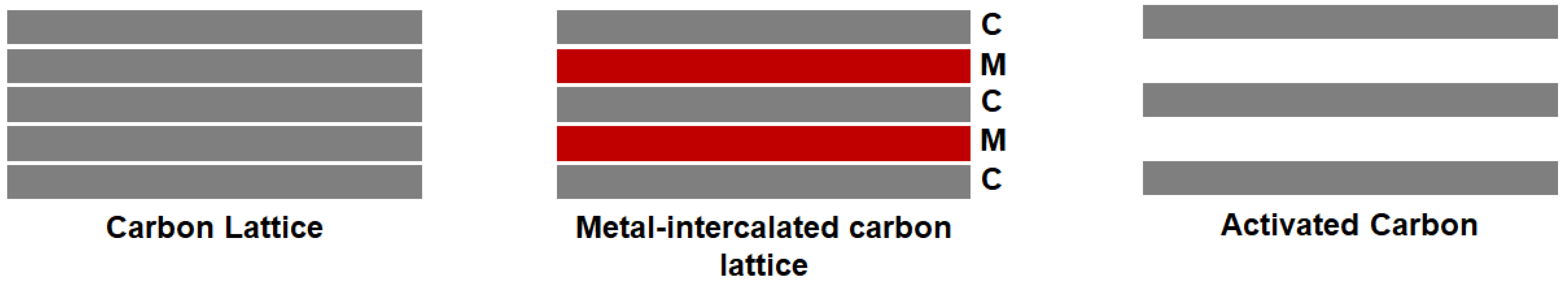
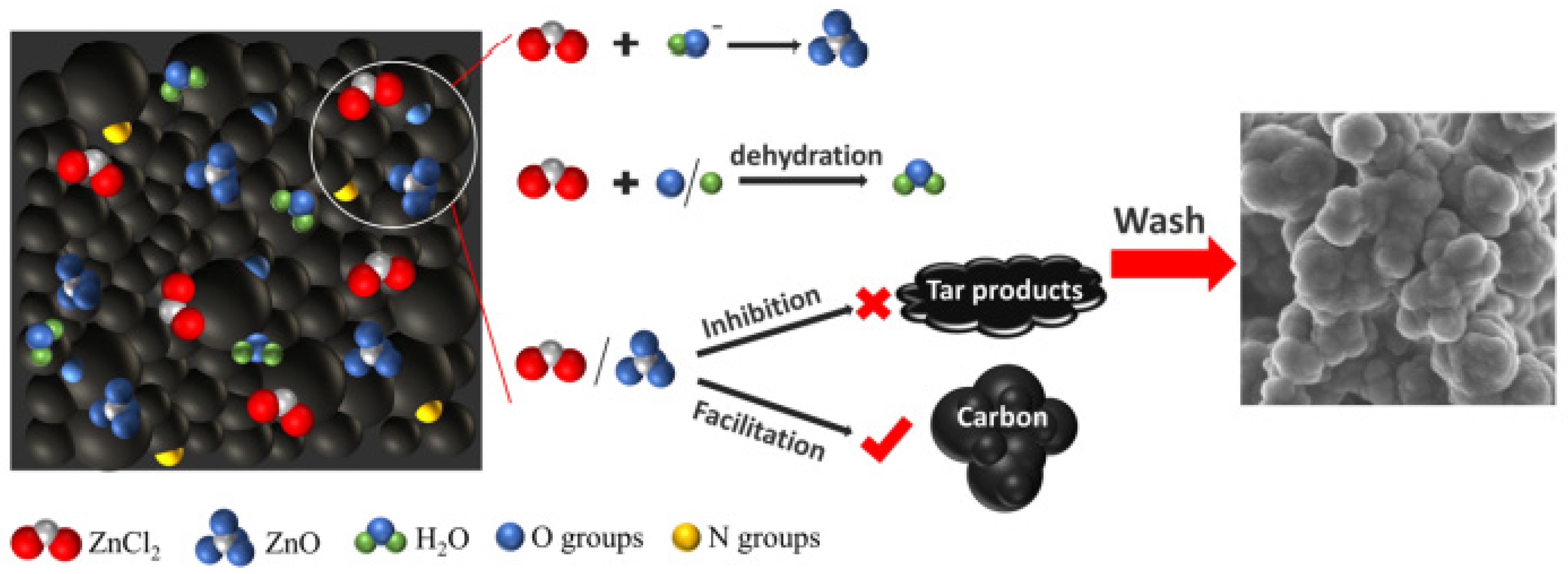
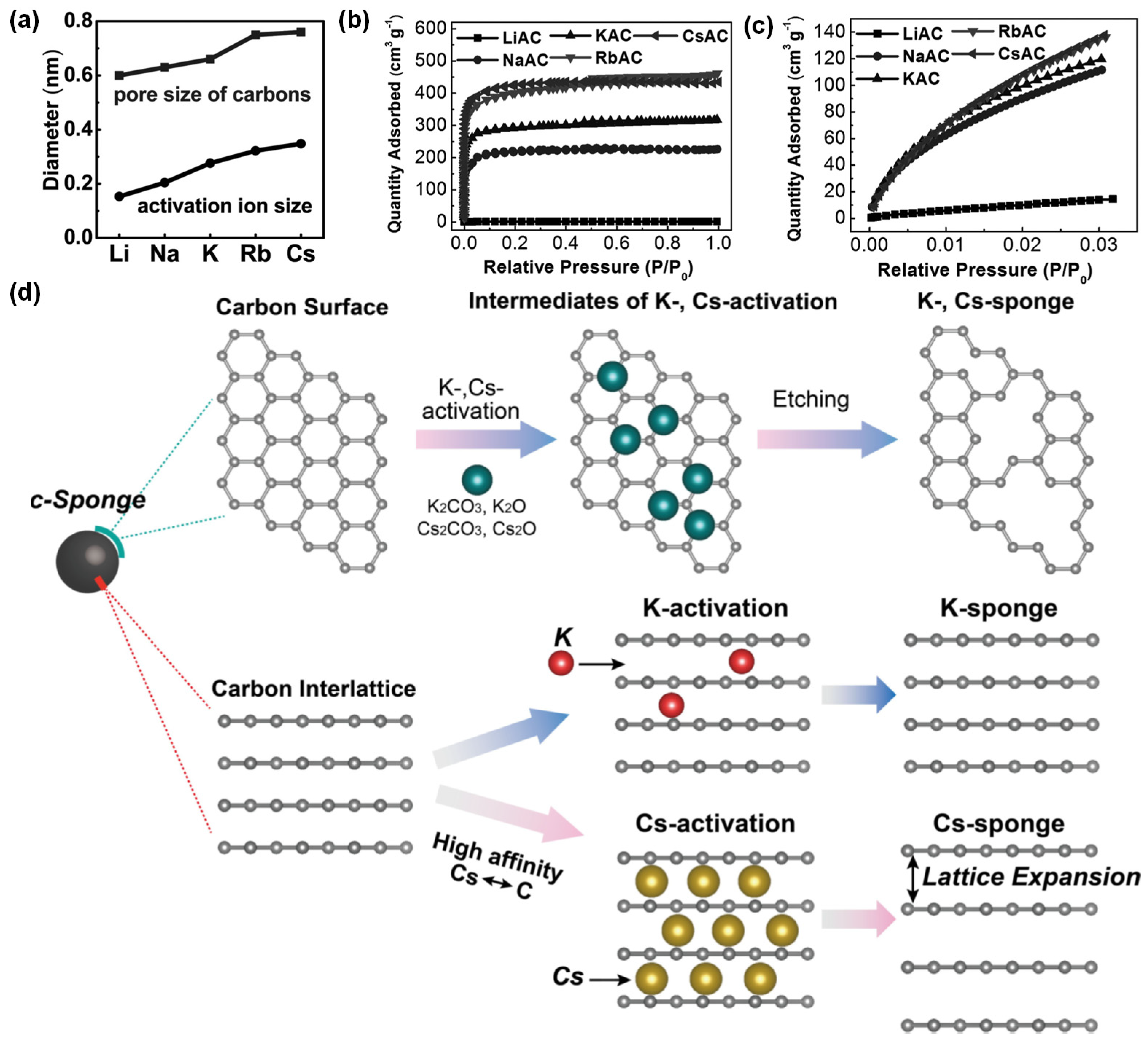
3.2.1. Metal-Based Compounds
3.2.2. Acids
3.2.3. Doping
| Labels | Carbonaceous Feedstock | Activation Condition [a] | Adsorption Condition | CO2 Adsorption (mmol/g) | CO2/N2 Selectivity [b] | Ref. |
|---|---|---|---|---|---|---|
| a-CL | Celtuce Leaf | KOH, 800 °C, 1 h | 25 °C, 1 bar | 4.18 | - | [51] |
| AC1 | Bamboo chips | 80% H3PO4, 500 °C, 4 h | 25 °C, 50 bar | 18.00 | 7.22 [c] | [67] |
| AC2 | Rubber seed shell | Ionic liquid, 800 °C | 25 °C, 1 bar | 2.27 | - | [79] |
| AC-2.5-600 | Date seeds | KOH (2.5:1), 600 °C, 1 h | 25 °C, 1 bar | 2.18 | - | [80] |
| AC-5 | Rice husk | KOH (1:2), 600 °C, 1 h | 25 °C, 1 bar | 2.10 | - | [69] |
| AC-850-3-NH3-650 | Pennsylvania anthracite | NH3, 650 °C, 90 min | 30 °C, 1 bar | 2.55 | - | [35] |
| AC-850-3-PEI | Pennsylvania anthracite | Wet impregnation with PEI | 30 °C, 1 bar | 0.21 | - | [35] |
| AC-KOH | Corncob | KOH, 600 °C, 1 h | 30 °C, 1 bar | 3.39 | - | [64] |
| AC-PA | Corncob | H3PO4, 600 °C, 1 h | 30 °C, 1 bar | 2.25 | - | [64] |
| AC-ZnCl | Corncob | ZnCl2, 600 °C, 1 h | 30 °C, 1 bar | 2.84 | - | [64] |
| AN800 | Raw almond shells | NH3, 800 °C, 2 h | 25 °C, 1 bar | 2.18 | - | [33] |
| AOS-A900 (45%)–PEI | Air-oxidized olive stones | Wet impregnation with PEI | 25 °C, 1 bar | 1.98 | - | [30] |
| AOS-NH2 | Air-oxidized olive stones | NH3, 400 °C, 2 h | 25 °C, 1 bar | 2.25 | - | [30] |
| AOS-NO400 | Air-oxidized olive stones | 8% NH3 (balance air), 400 °C, 2 h | 25 °C, 1 bar | 2.11 | - | [30] |
| CA-HC300 | Glucose | KOH (1:2), 800 °C, 1.5 h | 25 °C, 1 bar | 4.30 | - | [54] |
| CAC-5 | Rice husk with chitosan | KOH (1:2), 600 °C, 1 h | 25 °C, 1 bar | 3.68 | - | [69] |
| CeO2/AC | Charcoal activated carbon | Ce(NO3)2·6H2O | 25 °C, 1 bar | 1.20 | - | [81] |
| Coal-K-Im | Coal | KOH, 850 °C, 1 h | 25 °C, 1 bar | 5.88 | - | [52] |
| CP-600 | Trimethylsilyl imidazole, chloroacetonitrile | N2, 600 °C, 2 h | 25 °C, 1 bar | 1.82 | 54 | [73] |
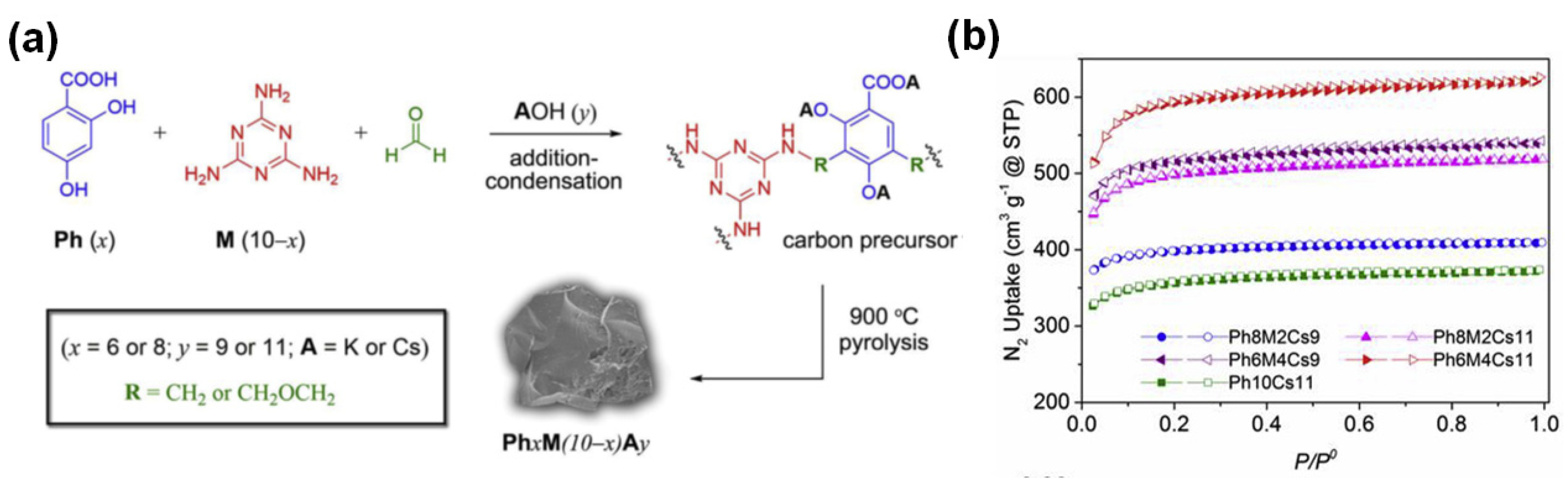
| CsAC | 2,4-dihydroxybenzoic acid (Ph), formaldehyde | CsOH, 900 °C, 2 h | 25 °C, 20 bar | 9.18 | - | [49] |
| Cs-sponge-600 | Marine sponge | CsOH, 600 °C, 1 h | 25 °C, 1 bar | 6.09 | 33 [c] | [50] |
| CuO(0.6)/AC | Commercial activated carbon | Cu(NO3)2·3H2O, 350 °C, 4 h | 30 °C, 1 bar | 2.20 | 60 | [82] |
| H2 | Eucalyptus camaldulensis wood | H3PO4 (2:1), 450 °C, 1 h | 30 °C, 1 bar | 2.98 | - | [20] |
| HK | Eucalyptus camaldulensis wood | KOH (3.5:1), 900 °C, 1 h | 30 °C, 1 bar | 4.10 | - | [20] |
| HTA-400 | Granular activated carbon (palm shell) | NH3, 400 °C, 2 h | 30 °C, 1 bar | 1.41 | - | [77] |
| HTA-800 | Granular activated carbon (palm shell) | NH3, 800 °C, 2 h | 30 °C, 1 bar | 1.64 | - | [77] |
| KOH:FPV_850-1 | Commercial activated carbon | KOH (1:1), 850 °C | 25 °C, 35 bar | 16.29 | - | [55] |
| K-sponge-700 | Marine sponge | KOH, 900 °C, 2 h | 25 °C, 1 bar | 4.82 | 9 [c] | [50] |
| L-A850 (40%)—PEI | Sewage sludge | Wet impregnation with PEI | 25 °C, 1 bar | 0.32 | - | [30] |
| MCa2FAL | African palm stones (lignocellulosic precursors) | H3PO4 + CaCl2, 450 °C, 2 h | 0 °C, 1 bar | 7.20 | - | [68] |
| MP48FAL | African palm stones (lignocellulosic precursors) | H3PO4, 600 °C, 2 h | 0 °C, 1 bar | 4.10 | - | [68] |
| N-DETA | Commercial activated carbon (Norit CGP Super) | Wet impregnation with DETA (60 °C, 300 mbar, 30 min) | 25 °C, 0.005 bar | 0.27 | - | [76] |
| N-PEHA | Commercial activated carbon (Norit CGP Super) | Wet impregnation with PEHA (60 °C, 300 mbar, 30 min) | 25 °C, 0.005 bar | 0.85 | - | [76] |
| N-PEI | Commercial activated carbon (Norit CGP Super) | Wet impregnation with PEI (60 °C, 300 mbar, 30 min) | 25 °C, 0.005 bar | 0.36 | - | [76] |
| NAC-1.5-600 [b] | Trimethylsilyl imidazole, chloroacetonitrile | KOH (1.5:1), 600 °C, 2 h | 25 °C, 1 bar | 5.39 | 62 | [73] |
| OMCreo CA 4:1 850 | Ordered mesoporous silica templated with creosote | KOH (4:1), 850 °C, 1 h | 25 °C, 1 bar | 4.19 | - | [39] |
| OXA-400 | Granular activated carbon (palm shell) | 50% NH3 (balance air), 400 °C, 2 h | 30 °C, 1 bar | 0.95 | - | [77] |
| OXA-800 | Granular activated carbon (palm shell) | 50% NH3 (balance air), 800 °C, 2 h | 30 °C, 1 bar | 1.48 | - | [77] |
| PAC-2 | Vitamin B9 | KOH (2:1), 800 °C, 2 h | 25 °C, 1 bar | 3.66 | - | [83] |
| PCSK-2-3-800 | Poplar sawdust, sulfur containing waste liquid | K2C2O4, 800 °C, 2 h | 25 °C, 1 bar | 3.80 | - | [84] |
| Ph8M2Cs11 | 2,4-dihydroxybenzoic acid (Ph), melamine and formaldehyde | CsOH, 900 °C, 2 h | 0 °C, 1 bar | 3.64 | - | [36] |
| Ph6M4K11 | 2,4-dihydroxybenzoic acid (Ph), melamine and formaldehyde | KOH, 900 °C, 2 h | 0 °C, 1 bar | 3.19 | - | [36] |
| PR4-700 | Hexamethylenetetramine and novolac-type phenolic resins | KOH (1:1), 700 °C, 1 h | 25 °C, 1 bar | 3.65 | - | [41] |
| SBL-MIP-800 | Molecularly imprinted polymer with sugar beet leaves | KOH (2:1), 800 °C, 1 h | 25 °C, 25 bar | 17.90 | 13.7 | [85] |
| VR5-1:1 | Aliphatic vacuum residue with 5% mesophase content | KOH (1:1), 800 °C, 2 h | 25 °C, 1 bar | 3.63 | - | [53] |
| VR5-4:1 | Aliphatic vacuum residue with 5% mesophase content | KOH (4:1), 800 °C, 2 h | 25 °C, 45 bar | 34.09 | - | [53] |
| Z0.75 | Eucalyptus camaldulensis wood | ZnCl2 (0.75:1), 500 °C, 2 h | 30 °C, 1 bar | 1.90 | - | [20] |
| - | Binary mixture of petroleum coke–palm kernel shell | K2CO3, 700 °C | 25 °C, 1 bar | 2.40 | - | [42] |
| - | Olive waste | H3PO4 (1:1), 600 °C | 25 °C, 18 bar | 7.60 | - | [66] |
| - | Petroleum coke | K2CO3, 700 °C | 25 °C, 1 bar | 2.26 | - | [42] |
4. Evaluation of the Separation Performance of Activated Carbon in CO2 Capture
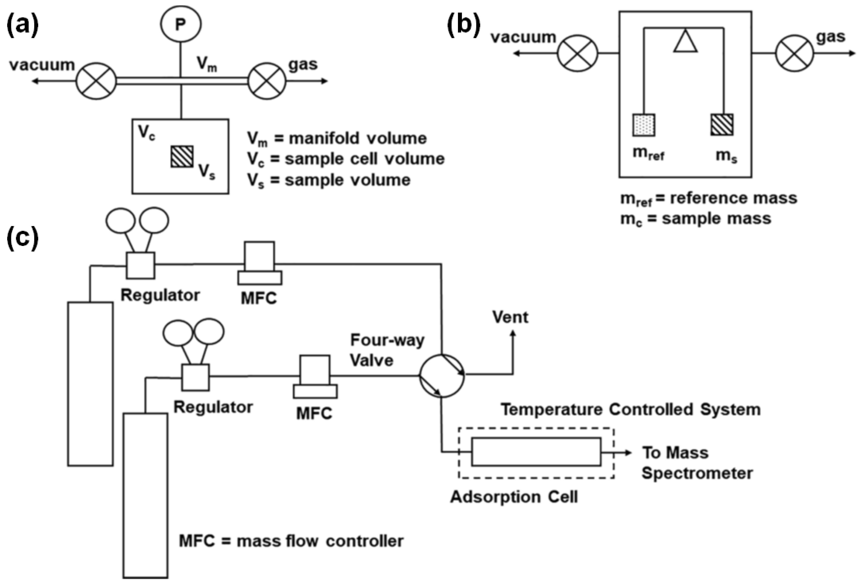
4.1. Equilibrium Gas Adsorption Isotherm
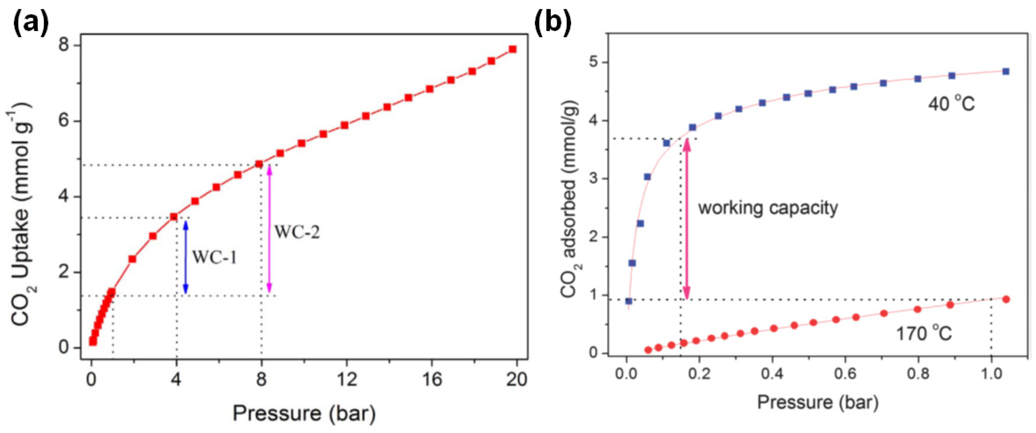
4.2. Breakthrough Measurement
4.3. Idealized Swing Adsorption
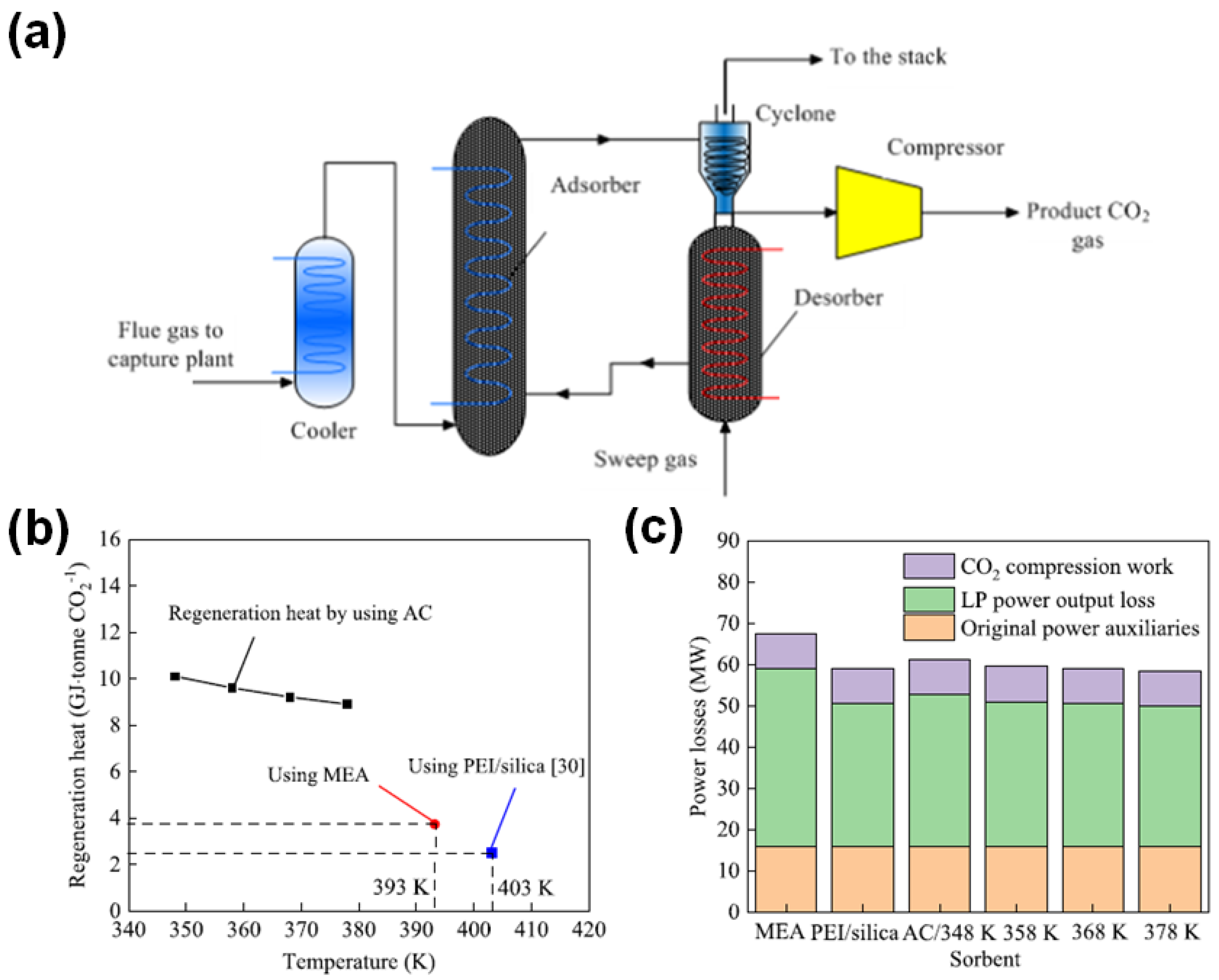
5. Potential Utilization of Activated Carbon in Simulation and Pilot Scale Studies
6. Conclusions and Future Perspective
Author Contributions
Funding
Data Availability Statement
Conflicts of Interest
References
- Chuah, C.Y.; Lee, J.; Bao, Y.; Song, J.; Bae, T.-H. High-performance porous carbon-zeolite mixed-matrix membranes for CO2/N2 separation. J. Membr. Sci. 2021, 622, 119031. [Google Scholar] [CrossRef]
- Lee, J.; Chuah, C.Y.; Tan, W.S.; Song, J.; Bae, T.-H. 3D-printed monolithic porous adsorbents from a solution-processible, hypercrosslinkable, functionalizable polymer. Chem. Eng. J. 2022, 427, 130883. [Google Scholar] [CrossRef]
- Yang, Y.; Chuah, C.Y.; Bae, T.-H. Polyamine-Appended Porous Organic Copolymers with Controlled Structural Properties for Enhanced CO2 Capture. ACS Sustain. Chem. Eng. 2021, 9, 2017–2026. [Google Scholar] [CrossRef]
- Chuah, C.Y.; Li, W.; Samarasinghe, S.; Sethunga, G.; Bae, T.-H. Enhancing the CO2 separation performance of polymer membranes via the incorporation of amine-functionalized HKUST-1 nanocrystals. Micropor. Mesopor. Mater. 2019, 290, 109680. [Google Scholar] [CrossRef]
- Samarasinghe, S.; Chuah, C.Y.; Yang, Y.; Bae, T.-H. Tailoring CO2/CH4 separation properties of mixed-matrix membranes via combined use of two-and three-dimensional metal-organic frameworks. J. Membr. Sci. 2018, 557, 30–37. [Google Scholar] [CrossRef]
- Sharma, A.; Jindal, J.; Mittal, A.; Kumari, K.; Maken, S.; Kumar, N. Carbon materials as CO2 adsorbents: A review. Environ. Chem. Lett. 2021, 19, 875–910. [Google Scholar] [CrossRef]
- Chuah, C.Y.; Kim, K.; Lee, J.; Koh, D.-Y.; Bae, T.-H. CO2 absorption using membrane contactors: Recent progress and future perspective. Ind. Eng. Chem. Res. 2019, 59, 6773–6794. [Google Scholar] [CrossRef]
- Chuah, C.Y.; Goh, K.; Yang, Y.; Gong, H.; Li, W.; Karahan, H.E.; Guiver, M.D.; Wang, R.; Bae, T.-H. Harnessing filler materials for enhancing biogas separation membranes. Chem. Rev. 2018, 118, 8655–8769. [Google Scholar] [CrossRef]
- Fagerlund, J.; Zevenhoven, R.; Thomassen, J.; Tednes, M.; Abdollahi, F.; Thomas, L.; Nielsen, C.J.; Mikoviny, T.; Wisthaler, A.; Zhu, L. Performance of an amine-based CO2 capture pilot plant at the Klemetsrud waste incinerator in Oslo, Norway. Int. J. Greenh. Gas Control 2021, 106, 103242. [Google Scholar] [CrossRef]
- Natewong, P.; Prasongthum, N.; Reubroycharoen, P.; Idem, R. Evaluating the CO2 capture performance using a BEA-AMP biblend amine solvent with novel high-performing absorber and desorber catalysts in a bench-scale CO2 capture pilot plant. Energy Fuels 2019, 33, 3390–3402. [Google Scholar] [CrossRef]
- Chahen, L.; Huard, T.; Cuccia, L.; Cuzuel, V.; Dugay, J.; Pichon, V.; Vial, J.; Gouedard, C.; Bonnard, L.; Cellier, N. Comprehensive monitoring of MEA degradation in a post-combustion CO2 capture pilot plant with identification of novel degradation products in gaseous effluents. Int. J. Greenh. Gas Control 2016, 51, 305–316. [Google Scholar] [CrossRef]
- Blanchon le Bouhelec, E.; Mougin, P.; Barreau, A.; Solimando, R. Rigorous modeling of the acid gas heat of absorption in alkanolamine solutions. Energy Fuels 2007, 21, 2044–2055. [Google Scholar] [CrossRef]
- Sumida, K.; Rogow, D.L.; Mason, J.A.; McDonald, T.M.; Bloch, E.D.; Herm, Z.R.; Bae, T.-H.; Long, J.R. Carbon dioxide capture in metal–organic frameworks. Chem. Rev. 2012, 112, 724–781. [Google Scholar] [CrossRef]
- Chuah, C.Y. Microporous Materials with Tailored Structural Properties for Enhanced Gas Separation; Nanyang Technological University: Singapore, 2019. [Google Scholar]
- Creamer, A.E.; Gao, B. Carbon-based adsorbents for postcombustion CO2 capture: A critical review. Environ. Sci. Technol. 2016, 50, 7276–7289. [Google Scholar] [CrossRef]
- Chuah, C.Y.; Li, W.; Yang, Y.; Bae, T.-H. Evaluation of porous adsorbents for CO2 capture under humid conditions: The importance of recyclability. Chem. Eng. J. Adv. 2020, 3, 100021. [Google Scholar] [CrossRef]
- Yang, Y.; Chuah, C.Y.; Gong, H.; Bae, T.-H. Robust microporous organic copolymers containing triphenylamine for high pressure CO2 capture application. J. CO2 Util. 2017, 19, 214–220. [Google Scholar] [CrossRef]
- Shafeeyan, M.S.; Daud, W.M.A.W.; Houshmand, A.; Shamiri, A. A review on surface modification of activated carbon for carbon dioxide adsorption. J. Anal. Appl. Pyrolysis 2010, 89, 143–151. [Google Scholar] [CrossRef]
- González-García, P. Activated carbon from lignocellulosics precursors: A review of the synthesis methods, characterization techniques and applications. Renew. Sustain. Energy Rev. 2018, 82, 1393–1414. [Google Scholar] [CrossRef]
- Heidari, A.; Younesi, H.; Rashidi, A.; Ghoreyshi, A. Adsorptive removal of CO2 on highly microporous activated carbons prepared from Eucalyptus camaldulensis wood: Effect of chemical activation. J. Taiwan Inst. Chem. Eng. 2014, 45, 579–588. [Google Scholar] [CrossRef]
- Caglayan, B.S.; Aksoylu, A.E. CO2 adsorption on chemically modified activated carbon. J. Hazard. Mater. 2013, 252, 19–28. [Google Scholar] [CrossRef]
- Carruthers, J.D.; Petruska, M.A.; Krishnan, G.; Hornbostel, M.; Bao, J. A New Activated Carbon for CO2 Capture from Coal-Fired Boiler Flue Gas. Adsorp. Sci. Technol. 2013, 31, 185–197. [Google Scholar] [CrossRef]
- Rodriguez-Reinoso, F.; Martin-Martinez, J.; Molina-Sabio, M.; Pérez-Lledó, I.; Prado-Burguete, C. A comparison of the porous texture of two CO2 activated botanic materials. Carbon 1985, 23, 19–24. [Google Scholar] [CrossRef]
- Savova, D.; Apak, E.; Ekinci, E.; Yardim, F.; Petrov, N.; Budinova, T.; Razvigorova, M.; Minkova, V. Biomass conversion to carbon adsorbents and gas. Biomass Bioenergy 2001, 21, 133–142. [Google Scholar] [CrossRef]
- Linares-Solano, A.; De D. López-González, J.; Molina-Sabio, M.; Rodriguez-Reinoso, F. Active carbons from almond shells as adsorbents in gas and liquid phases. J. Chem. Technol. Biotechnol. 1980, 30, 65–72. [Google Scholar] [CrossRef]
- Chuah, C.Y.; Anwar, S.N.B.M.; Weerachanchai, P.; Bae, T.-H.; Goh, K.; Wang, R. Scaling-up defect-free asymmetric hollow fiber membranes to produce oxygen-enriched gas for integration into municipal solid waste gasification process. J. Membr. Sci. 2021, 640, 119787. [Google Scholar] [CrossRef]
- Plaza, M.; González, A.; Pis, J.; Rubiera, F.; Pevida, C. Production of microporous biochars by single-step oxidation: Effect of activation conditions on CO2 capture. Appl. Energy 2014, 114, 551–562. [Google Scholar] [CrossRef] [Green Version]
- González, A.; Plaza, M.; Rubiera, F.; Pevida, C. Sustainable biomass-based carbon adsorbents for post-combustion CO2 capture. Chem. Eng. J. 2013, 230, 456–465. [Google Scholar] [CrossRef] [Green Version]
- Khuong, D.A.; Nguyen, H.N.; Tsubota, T. Activated carbon produced from bamboo and solid residue by CO2 activation utilized as CO2 adsorbents. Biomass Bioenergy 2021, 148, 106039. [Google Scholar] [CrossRef]
- Plaza, M.G.; Pevida, C.; Arias, B.; Casal, M.; Martín, C.; Fermoso, J.; Rubiera, F.; Pis, J. Different approaches for the development of low-cost CO2 adsorbents. J. Environ. Eng. 2009, 135, 426–432. [Google Scholar] [CrossRef] [Green Version]
- Far, H.M.; Lawson, S.; Al-Naddaf, Q.; Rezaei, F.; Sotiriou-Leventis, C.; Rownaghi, A.A. Advanced pore characterization and adsorption of light gases over aerogel-derived activated carbon. Micropor. Mesopor. Mater. 2021, 313, 110833. [Google Scholar] [CrossRef]
- Ogungbenro, A.E.; Quang, D.V.; Al-Ali, K.A.; Vega, L.F.; Abu-Zahra, M.R. Physical synthesis and characterization of activated carbon from date seeds for CO2 capture. J. Environ. Chem. Eng. 2018, 6, 4245–4252. [Google Scholar] [CrossRef]
- Plaza, M.; Pevida, C.; Martín, C.F.; Fermoso, J.; Pis, J.; Rubiera, F. Developing almond shell-derived activated carbons as CO2 adsorbents. Sep. Purif. Technol. 2010, 71, 102–106. [Google Scholar] [CrossRef] [Green Version]
- Arena, U. Process and technological aspects of municipal solid waste gasification. A review. Waste Manag. 2012, 32, 625–639. [Google Scholar] [CrossRef] [PubMed]
- Maroto-Valer, M.M.; Tang, Z.; Zhang, Y. CO2 capture by activated and impregnated anthracites. Fuel Process. Technol. 2005, 86, 1487–1502. [Google Scholar] [CrossRef]
- Yang, Y.; Goh, K.; Chuah, C.Y.; Karahan, H.E.; Birer, Ö.; Bae, T.-H. Sub-Ångström-level engineering of ultramicroporous carbons for enhanced sulfur hexafluoride capture. Carbon 2019, 155, 56–64. [Google Scholar] [CrossRef]
- Zhang, J.; Gao, J.; Chen, Y.; Hao, X.; Jin, X. Characterization, preparation, and reaction mechanism of hemp stem based activated carbon. Results Phys. 2017, 7, 1628–1633. [Google Scholar] [CrossRef]
- Zhang, C.; Wang, Y.; Zhang, X.; Wang, R.; Kou, L.; Wang, J.; Li, R.; Fan, C. Millimeter-level nitrogen modified activated carbon spheres assisted Bi4Ti3O12 composites for bifunctional adsorption/photoreduction of CO2. Chem. Eng. J. 2021, 417, 128218. [Google Scholar] [CrossRef]
- García-Díez, E.; Castro-Muñiz, A.; Paredes, J.I.; Maroto-Valer, M.M.; Suárez-García, F.; García, S. CO2 capture by novel hierarchical activated ordered micro-mesoporous carbons derived from low value coal tar products. Micropor. Mesopor. Mater. 2021, 318, 110986. [Google Scholar] [CrossRef]
- Ogungbenro, A.E.; Quang, D.V.; Al-Ali, K.; Abu-Zahra, M.R. Activated carbon from date seeds for CO2 capture applications. Energy Procedia 2017, 114, 2313–2321. [Google Scholar] [CrossRef]
- Liu, J.; Sun, N.; Sun, C.; Liu, H.; Snape, C.; Li, K.; Wei, W.; Sun, Y. Spherical potassium intercalated activated carbon beads for pulverised fuel CO2 post-combustion capture. Carbon 2015, 94, 243–255. [Google Scholar] [CrossRef] [Green Version]
- Rashidi, N.A.; Yusup, S. Co-valorization of delayed petroleum coke–palm kernel shell for activated carbon production. J. Hazard. Mater. 2021, 403, 123876. [Google Scholar] [CrossRef] [PubMed]
- Wang, J.; Kaskel, S. KOH activation of carbon-based materials for energy storage. J. Mater. Chem. 2012, 22, 23710–23725. [Google Scholar] [CrossRef]
- Otowa, T.; Tanibata, R.; Itoh, M. Production and adsorption characteristics of MAXSORB: High-surface-area active carbon. Gas Sep. Purif. 1993, 7, 241–245. [Google Scholar] [CrossRef]
- Lozano-Castello, D.; Calo, J.; Cazorla-Amoros, D.; Linares-Solano, A. Carbon activation with KOH as explored by temperature programmed techniques, and the effects of hydrogen. Carbon 2007, 45, 2529–2536. [Google Scholar] [CrossRef]
- Raymundo-Pinero, E.; Azaïs, P.; Cacciaguerra, T.; Cazorla-Amorós, D.; Linares-Solano, A.; Béguin, F. KOH and NaOH activation mechanisms of multiwalled carbon nanotubes with different structural organisation. Carbon 2005, 43, 786–795. [Google Scholar] [CrossRef]
- Qiao, W.; Yoon, S.-H.; Mochida, I. KOH activation of needle coke to develop activated carbons for high-performance EDLC. Energy Fuels 2006, 20, 1680–1684. [Google Scholar] [CrossRef]
- Wang, H.; Gao, Q.; Hu, J. High hydrogen storage capacity of porous carbons prepared by using activated carbon. J. Am. Chem. Soc. 2009, 131, 7016–7022. [Google Scholar] [CrossRef]
- Zhou, J.; Li, Z.; Xing, W.; Shen, H.; Bi, X.; Zhu, T.; Qiu, Z.; Zhuo, S. A new approach to tuning carbon ultramicropore size at sub-angstrom level for maximizing specific capacitance and CO2 uptake. Adv. Funct. Mater. 2016, 26, 7955–7964. [Google Scholar] [CrossRef]
- Lee, H.J.; Ko, D.; Kim, J.S.; Park, Y.; Hwang, I.; Yavuz, C.T.; Choi, J.W. Cesium Ion-Mediated Microporous Carbon for CO2 Capture and Lithium-Ion Storage. ChemNanoMat 2021, 7, 150–157. [Google Scholar] [CrossRef]
- Wang, R.; Wang, P.; Yan, X.; Lang, J.; Peng, C.; Xue, Q. Promising porous carbon derived from celtuce leaves with outstanding supercapacitance and CO2 capture performance. ACS Appl. Mater. Interfaces 2012, 4, 5800–5806. [Google Scholar] [CrossRef]
- Boujibar, O.; Ghamouss, F.; Ghosh, A.; Achak, O.; Chafik, T. Efficient CO2 Capture by Ultra-high Microporous Activated Carbon Made from Natural Coal. Chem. Eng. Technol. 2021, 44, 148–155. [Google Scholar] [CrossRef]
- Casco, M.E.; Martínez-Escandell, M.; Silvestre-Albero, J.; Rodríguez-Reinoso, F. Effect of the porous structure in carbon materials for CO2 capture at atmospheric and high-pressure. Carbon 2014, 67, 230–235. [Google Scholar] [CrossRef] [Green Version]
- Zhang, Z.; Luo, D.; Lui, G.; Li, G.; Jiang, G.; Cano, Z.P.; Deng, Y.-P.; Du, X.; Yin, S.; Chen, Y. In-situ ion-activated carbon nanospheres with tunable ultramicroporosity for superior CO2 capture. Carbon 2019, 143, 531–541. [Google Scholar] [CrossRef]
- Sreńscek-Nazzal, J.; Kiełbasa, K. Advances in modification of commercial activated carbon for enhancement of CO2 capture. Appl. Surf. Sci. 2019, 494, 137–151. [Google Scholar] [CrossRef]
- Kim, J.-H.; Lee, G.; Park, J.-E.; Kim, S.-H. Limitation of K2CO3 as a Chemical Agent for Upgrading Activated Carbon. Processes 2021, 9, 1000. [Google Scholar] [CrossRef]
- Montes, V.; Hill, J.M. Activated carbon production: Recycling KOH to minimize waste. Mat. Lett. 2018, 220, 238–240. [Google Scholar] [CrossRef]
- Hayashi, J.i.; Horikawa, T.; Takeda, I.; Muroyama, K.; Ani, F.N. Preparing activated carbon from various nutshells by chemical activation with K2CO3. Carbon 2002, 40, 2381–2386. [Google Scholar] [CrossRef]
- Hayashi, J.i.; Horikawa, T.; Muroyama, K.; Gomes, V.G. Activated carbon from chickpea husk by chemical activation with K2CO3: Preparation and characterization. Micropor. Mesopor. Mater. 2002, 55, 63–68. [Google Scholar] [CrossRef]
- Lu, C.; Xu, S.; Liu, C. The role of K2CO3 during the chemical activation of petroleum coke with KOH. J. Anal. Appl. Pyrolysis 2010, 87, 282–287. [Google Scholar] [CrossRef]
- Chen, R.; Li, L.; Liu, Z.; Lu, M.; Wang, C.; Li, H.; Ma, W.; Wang, S. Preparation and characterization of activated carbons from tobacco stem by chemical activation. J. Air Waste Manag. Assoc. 2017, 67, 713–724. [Google Scholar] [CrossRef] [Green Version]
- Liu, Z.; Huang, Y.; Zhao, G. Preparation and characterization of activated carbon fibers from liquefied wood by ZnCl2 activation. BioResources 2016, 11, 3178–3190. [Google Scholar] [CrossRef] [Green Version]
- Li, B.; Hu, J.; Xiong, H.; Xiao, Y. Application and properties of microporous carbons activated by ZnCl2: Adsorption behavior and activation mechanism. ACS Omega 2020, 5, 9398–9407. [Google Scholar] [CrossRef] [PubMed] [Green Version]
- Sarwar, A.; Ali, M.; Khoja, A.H.; Nawar, A.; Waqas, A.; Liaquat, R.; Naqvi, S.R.; Asjid, M. Synthesis and characterization of biomass-derived surface-modified activated carbon for enhanced CO2 adsorption. J. CO2 Util. 2021, 46, 101476. [Google Scholar] [CrossRef]
- Li, Y.; Zhang, X.; Yang, R.; Li, G.; Hu, C. The role of H3PO4 in the preparation of activated carbon from NaOH-treated rice husk residue. RSC Adv. 2015, 5, 32626–32636. [Google Scholar] [CrossRef]
- Almoneef, M.; Jedli, H.; Mbarek, M. Experimental study of CO2 adsorption using activated carbon. Mater. Res. Express 2021, 8, 065602. [Google Scholar] [CrossRef]
- Wang, Y.; Liu, C.; Zhou, Y. Preparation and adsorption performances of mesopore-enriched bamboo activated carbon. Front. Chem. Eng. China 2008, 2, 473–477. [Google Scholar] [CrossRef]
- Vargas, D.; Balsamo, M.; Giraldo, L.; Erto, A.; Lancia, A.; Moreno-Piraján, J. Equilibrium and dynamic CO2 adsorption on activated carbon honeycomb monoliths. Ind. Eng. Chem. Res. 2016, 55, 7898–7905. [Google Scholar] [CrossRef]
- He, S.; Chen, G.; Xiao, H.; Shi, G.; Ruan, C.; Ma, Y.; Dai, H.; Yuan, B.; Chen, X.; Yang, X. Facile preparation of N-doped activated carbon produced from rice husk for CO2 capture. J. Colloid. Interface Sci. 2021, 582, 90–101. [Google Scholar] [CrossRef]
- Lee, Y.; Chuah, C.Y.; Lee, J.; Bae, T.-H. Effective functionalization of porous polymer fillers to enhance CO2/N2 separation performance of mixed-matrix membranes. J. Membr. Sci. 2022, 647, 120309. [Google Scholar] [CrossRef]
- Yang, Y.; Chuah, C.Y.; Bae, T.-H. Polyamine-appended porous organic polymers for efficient post-combustion CO2 capture. Chem. Eng. J. 2019, 358, 1227–1234. [Google Scholar] [CrossRef]
- Xing, W.; Liu, C.; Zhou, Z.; Zhang, L.; Zhou, J.; Zhuo, S.; Yan, Z.; Gao, H.; Wang, G.; Qiao, S.Z. Superior CO2 uptake of N-doped activated carbon through hydrogen-bonding interaction. Energy Environ. Sci. 2012, 5, 7323–7327. [Google Scholar] [CrossRef]
- Sethia, G.; Sayari, A. Comprehensive study of ultra-microporous nitrogen-doped activated carbon for CO2 capture. Carbon 2015, 93, 68–80. [Google Scholar] [CrossRef]
- Yang, Y.; Chuah, C.Y.; Bae, T.-H. Highly efficient carbon dioxide capture in diethylenetriamine-appended porous organic polymers: Investigation of structural variations of chloromethyl monomers. J. Ind. Eng. Chem. 2020, 88, 207–214. [Google Scholar] [CrossRef]
- Nguyen, T.H.; Kim, S.; Yoon, M.; Bae, T.H. Hierarchical zeolites with amine-functionalized mesoporous domains for carbon dioxide capture. ChemSusChem 2016, 9, 455–461. [Google Scholar] [CrossRef] [PubMed]
- Plaza, M.; Pevida, C.; Arenillas, A.; Rubiera, F.; Pis, J. CO2 capture by adsorption with nitrogen enriched carbons. Fuel 2007, 86, 2204–2212. [Google Scholar] [CrossRef] [Green Version]
- Shafeeyan, M.S.; Daud, W.M.A.W.; Houshmand, A.; Arami-Niya, A. Ammonia modification of activated carbon to enhance carbon dioxide adsorption: Effect of pre-oxidation. Appl. Surf. Sci. 2011, 257, 3936–3942. [Google Scholar] [CrossRef]
- Pereira, M.F.R.; Soares, S.F.; Órfão, J.J.; Figueiredo, J.L. Adsorption of dyes on activated carbons: Influence of surface chemical groups. Carbon 2003, 41, 811–821. [Google Scholar] [CrossRef]
- Mokti, N.; Borhan, A.; Zaine, S.N.A.; Zaid, H.F.M. Synthesis and Characterisation of Pyridinium-Based Ionic Liquid as Activating Agent in Rubber Seed Shell Activated Carbon Production for CO2 Capture. J. Adv. Res. Fluid Mech. Therm. Sci. 2021, 82, 85–95. [Google Scholar] [CrossRef]
- Abuelnoor, N.; AlHajaj, A.; Khaleel, M.; Vega, L.F.; Abu Zahra, M. Single Step Synthesis and Characterization of Activated Carbon from Date Seeds for CO2 Capture. In Proceedings of the 15th International Conference on Greenhouse Gas Control Technologies, Abu Dhabi, United Arab Emirates, 15–18 March 2021. [Google Scholar]
- Lahuri, A.H.; Ling, M.N.K.; Rahim, A.A.; Nordin, N. Adsorption kinetics for CO2 capture using cerium oxide impregnated on activated carbon. Acta Chim. Slov. 2020, 67, 570–580. [Google Scholar] [CrossRef]
- Chen, G.; Wang, F.; Wang, S.; Ji, C.; Wang, W.; Dong, J.; Gao, F. Facile fabrication of copper oxide modified activated carbon composite for efficient CO2 adsorption. Korean J. Chem. Eng. 2021, 38, 46–54. [Google Scholar] [CrossRef]
- Wang, X.; Hui, W.; Hu, A.; Li, X.; Li, Y.; Wang, H. A synthesis of porous activated carbon materials derived from vitamin B9 base for CO2 capture and conversion. Mater. Today Chem. 2021, 20, 100468. [Google Scholar] [CrossRef]
- Guo, X.; Zhang, G.; Wu, C.; Liu, J.; Li, G.; Zhao, Y.; Wang, Y.; Xu, Y. A cost-effective synthesis of heteroatom-doped porous carbon by sulfur-containing waste liquid treatment: As a promising adsorbent for CO2 capture. J. Environ. Chem. Eng. 2021, 9, 105165. [Google Scholar] [CrossRef]
- Park, J.; Cho, S.Y.; Jung, M.; Lee, K.; Nah, Y.-C.; Attia, N.F.; Oh, H. Efficient synthetic approach for nanoporous adsorbents capable of pre-and post-combustion CO2 capture and selective gas separation. J. CO2 Util. 2021, 45, 101404. [Google Scholar] [CrossRef]
- Thommes, M.; Kaneko, K.; Neimark, A.V.; Olivier, J.P.; Rodriguez-Reinoso, F.; Rouquerol, J.; Sing, K.S. Physisorption of gases, with special reference to the evaluation of surface area and pore size distribution (IUPAC Technical Report). Pure Appl. Chem. 2015, 87, 1051–1069. [Google Scholar] [CrossRef] [Green Version]
- Chuah, C.Y.; Lee, Y.; Bae, T.-H. Potential of adsorbents and membranes for SF6 capture and recovery: A review. Chem. Eng. J. 2021, 404, 126577. [Google Scholar] [CrossRef]
- Mason, J.A.; McDonald, T.M.; Bae, T.-H.; Bachman, J.E.; Sumida, K.; Dutton, J.J.; Kaye, S.S.; Long, J.R. Application of a high-throughput analyzer in evaluating solid adsorbents for post-combustion carbon capture via multicomponent adsorption of CO2, N2, and H2O. J. Am. Chem. Soc. 2015, 137, 4787–4803. [Google Scholar] [CrossRef] [Green Version]
- Myers, A.L.; Prausnitz, J.M. Thermodynamics of mixed-gas adsorption. AIChE J. 1965, 11, 121–127. [Google Scholar] [CrossRef]
- Li, W.; Chuah, C.Y.; Yang, Y.; Bae, T.-H. Nanocomposites formed by in situ growth of NiDOBDC nanoparticles on graphene oxide sheets for enhanced CO2 and H2 storage. Micropor. Mesopor. Mater. 2018, 265, 35–42. [Google Scholar] [CrossRef]
- Serre, C.; Bourrelly, S.; Vimont, A.; Ramsahye, N.A.; Maurin, G.; Llewellyn, P.L.; Daturi, M.; Filinchuk, Y.; Leynaud, O.; Barnes, P. An explanation for the very large breathing effect of a metal–organic framework during CO2 adsorption. Adv. Mater. 2007, 19, 2246–2251. [Google Scholar] [CrossRef]
- Lin, R.-B.; Li, L.; Wu, H.; Arman, H.; Li, B.; Lin, R.-G.; Zhou, W.; Chen, B. Optimized separation of acetylene from carbon dioxide and ethylene in a microporous material. J. Am. Chem. Soc. 2017, 139, 8022–8028. [Google Scholar] [CrossRef]
- Lee, J.; Chuah, C.Y.; Kim, J.; Kim, Y.; Ko, N.; Seo, Y.; Kim, K.; Bae, T.H.; Lee, E. Separation of acetylene from carbon dioxide and ethylene by a water-stable microporous metal–organic framework with aligned imidazolium groups inside the channels. Angew. Chem. Int. Ed. 2018, 130, 7995–7999. [Google Scholar] [CrossRef]
- Chuah, C.Y.; Goh, K.; Bae, T.-H. Hierarchically structured HKUST-1 nanocrystals for enhanced SF6 capture and recovery. J. Phys. Chem. C 2017, 121, 6748–6755. [Google Scholar] [CrossRef]
- Chuah, C.Y.; Yang, Y.; Bae, T.-H. Hierarchically porous polymers containing triphenylamine for enhanced SF6 separation. Micropor. Mesopor. Mater. 2018, 272, 232–240. [Google Scholar] [CrossRef]
- Chuah, C.Y.; Yu, S.; Na, K.; Bae, T.-H. Enhanced SF6 recovery by hierarchically structured MFI zeolite. J. Ind. Eng. Chem. 2018, 62, 64–71. [Google Scholar] [CrossRef]
- Bae, Y.S.; Snurr, R.Q. Development and evaluation of porous materials for carbon dioxide separation and capture. Angew. Chem. Int. Ed. 2011, 50, 11586–11596. [Google Scholar] [CrossRef]
- Bae, T.-H.; Hudson, M.R.; Mason, J.A.; Queen, W.L.; Dutton, J.J.; Sumida, K.; Micklash, K.J.; Kaye, S.S.; Brown, C.M.; Long, J.R. Evaluation of cation-exchanged zeolite adsorbents for post-combustion carbon dioxide capture. Energy Environ. Sci. 2013, 6, 128–138. [Google Scholar] [CrossRef]
- Jiang, L.; Gonzalez-Diaz, A.; Ling-Chin, J.; Roskilly, A.; Smallbone, A. Post-combustion CO2 capture from a natural gas combined cycle power plant using activated carbon adsorption. Appl. Energy 2019, 245, 1–15. [Google Scholar] [CrossRef]
- Yang, W.-C.; Hoffman, J. Exploratory design study on reactor configurations for carbon dioxide capture from conventional power plants employing regenerable solid sorbents. Ind. Eng. Chem. Res. 2009, 48, 341–351. [Google Scholar] [CrossRef]
- Majchrzak-Kucęba, I.; Wawrzyńczak, D.; Ściubidło, A.; Zdeb, J.; Smółka, W.; Zajchowski, A. Stability and regenerability of acivated carbon used for CO2 removal in pilot DR-VPSA unit in real power plant conditions. J. CO2 Util. 2019, 29, 1–11. [Google Scholar] [CrossRef]
- Wawrzyńczak, D.; Majchrzak-Kucęba, I.; Srokosz, K.; Kozak, M.; Nowak, W.; Zdeb, J.; Smółka, W.; Zajchowski, A. The pilot dual-reflux vacuum pressure swing adsorption unit for CO2 capture from flue gas. Sep. Purif. Technol. 2019, 209, 560–570. [Google Scholar] [CrossRef]


| Comparison | Physical Activation | Chemical Activation |
|---|---|---|
| General description |
|
|
| Operating conditions |
|
|
| Merits |
|
|
| Limitations |
|
|
| Possible reagents/mediums that can be adopted |
|
|
Publisher’s Note: MDPI stays neutral with regard to jurisdictional claims in published maps and institutional affiliations. |
© 2022 by the authors. Licensee MDPI, Basel, Switzerland. This article is an open access article distributed under the terms and conditions of the Creative Commons Attribution (CC BY) license (https://creativecommons.org/licenses/by/4.0/).
Share and Cite
Chuah, C.Y.; Laziz, A.M. Recent Progress in Synthesis and Application of Activated Carbon for CO2 Capture. C 2022, 8, 29. https://doi.org/10.3390/c8020029
Chuah CY, Laziz AM. Recent Progress in Synthesis and Application of Activated Carbon for CO2 Capture. C. 2022; 8(2):29. https://doi.org/10.3390/c8020029
Chicago/Turabian StyleChuah, Chong Yang, and Afiq Mohd Laziz. 2022. "Recent Progress in Synthesis and Application of Activated Carbon for CO2 Capture" C 8, no. 2: 29. https://doi.org/10.3390/c8020029
APA StyleChuah, C. Y., & Laziz, A. M. (2022). Recent Progress in Synthesis and Application of Activated Carbon for CO2 Capture. C, 8(2), 29. https://doi.org/10.3390/c8020029