Article

Pore Structure and Gas Diffusion Features of Ionic Liquid-Derived Carbon Membranes

by
Ourania Tzialla
1,
Anastasios Labropoulos
1,*,
Georgios Pilatos
1,
Georgios Romanos
1 and
Konstantinos G. Beltsios
2,*
1
National Center for Scientific Research Demokritos, Institute of Nanoscience & Nanotechnology, Aghia Paraskevi, 15310 Athens, Greece
2
School of Chemical Engineering, National Technical University of Athens, Zografou Campus, 15780 Athens, Greece
*
Authors to whom correspondence should be addressed.
Submission received: 7 April 2022 / Revised: 24 April 2022 / Accepted: 25 April 2022 / Published: 29 April 2022

Abstract

:
In the present study, the concept of Ionic Liquid (IL)-mediated formation of carbon was applied to derive composite membranes bearing a nanoporous carbon phase within their separation layer. Thermolytic carbonization of the supported ionic liquid membranes, prepared by infiltration of the IL 1-methyl-3-butylimidazolium tricyanomethanide into the porous network of Vycor® porous glass tubes, was applied to derive the precursor Carbon/Vycor® composites. All precursors underwent a second cycle of IL infiltration/pyrolysis with the target to finetune the pore structural characteristics of the carbonaceous matter nesting inside the separation layer. The pore structural assets and evolution of the gas permeation properties and separation efficiency of the as-derived composite membranes were investigated with reference to the duration of the second infiltration step. The transport mechanisms of the permeating gases were elucidated and correlated to the structural characteristics of the supported carbon phase and the analysis of LN2 adsorption isotherms. Regarding the gas separation efficiency of the fabricated Carbon/Vycor® composite membranes, He/CO2 ideal selectivity values as high as 4.31 at 1 bar and 25 °C and 4.64 at 0.3 bar and 90 °C were achieved. In addition, the CO2/N2 ideal selectivity becomes slightly improved for longer second-impregnation times.

1. Introduction

In recent years, membrane technology has been exploited in a wide range of gas purification and separation applications. Compared to conventional gas separation technologies, membrane-based technologies are characterized by high energy-efficiency, reduced operational expenses, continuous operation modes, avoidance of hazardous solvents and lower environmental impact, ease of installation and use, and flexibility in unit design [1]. Therefore, gas separation processes implementing either polymeric or inorganic membranes have the potential to replace conventional separation processes such as distillation, absorption, adsorption, and cryogenic technologies.
Inorganic porous membranes bearing ceramic, carbon, or porous glass molecular sieving barriers are mechanically tough, chemically inert, reliable, and high-performance materials that have shown potential for application in harsh environments encountered in large-scale processes carried out in thermal power plants and refineries, such as the dry reforming of methane [2,3] and hydrogen separation [4,5]. Intensification of processes utilizing inorganic membranes has been applied for O2/N2 separation [6,7], natural gas purification [8,9], and separation of CO2 from other gases in industrial applications such as biogas purification [10], and CO2 capture from power plant combustion exhausts [11,12,13].
Modifications of commercial or laboratory-made inorganic porous membranes are aimed at tuning their pore size, mending nano-dimensional voids, or altering their physicochemical properties, hence endowing membranes with assets of high hydrothermal stability and specific gas/surface interactions toward improving their separation performance and sustainability. Effective modification techniques include infiltration or dip-coating in liquid solvents or solutions of metal salts, usually followed by calcination or pyrolysis [14], chemical vapor deposition (CVD) [15], metal organic CVD [16], and post-oxidation [17]. Supported liquid membranes (SLMs) are usually microfiltration membranes encompassing an organic solvent that is immobilized within their pores. The organic solvent contains a carrier (complexing agent) that selectively binds one of the feed components and is responsible for the transfer of the specific component across the membrane [18].
Another important form of composite membranes with a modified porous structure corresponds to Supported Ionic Liquid Membranes (SILMs); i.e., to membranes that bear an immobilized ionic liquid phase in their pore network [19,20,21,22]. The IL immobilization can be accomplished by either physical imbibition [21,23] or a chemical grafting synthetic route, such as the grafting-to method [24]. The solubility and diffusion of several gases have already been studied in a great number of Room Temperature Ionic Liquids (RTILs) [25,26,27] and the results have shown a very promising CO2 absorption capacity and CO2/N2 separation selectivity that might be suitable for energy and environmental applications, such as carbon capture and sequestration (CCS). In general, diffusion of IL-soluble gases such as CO2 and SO2 in the porous SILMs proceeds through a combination of diffusion in pores and dissolution/diffusion in the supported IL phase [21].
Carbon molecular sieving membranes (CMSMs) are usually produced through heat treatment (pyrolytic, hydrothermal, or under mild oxidative conditions) of flat or hollow-fiber polymer membrane precursors. The chemical composition, porous structure (pore size distribution, mean pore size, porosity, possible presence of defects, etc.), nature and concentration of sorption sites, permeation properties, and separation efficiency are highly dependent on the polymer material composition and the applied carbonization conditions [28,29]. Up to now, numerous polymeric precursors have been subjected to a variety of carbonization processes in order to develop CMSMs with excellent separation performances. These precursors include polyimides, cellulose, poly(furfuryl alcohol), polyetherimide, polyacrylonitrile, poly(vinylidene chloride), phenolic resins, and resorcinol-formaldehyde resins, etc. [30,31]. Amorphous microporous carbon membranes are promising materials for gas separation applications because of their superior thermal resistance, chemical stability in corrosive environments, higher gas permeabilities, and exceptional separation selectivity compared to available polymeric membranes. Furthermore, a major drawback avoided with the use of carbon membranes is that they are not plasticized when operated under high pressure or high CO2 content, which would deteriorate the separation efficiency. Further improvements on membrane structural quality and separation performance can potentially offset the relatively high fabrication cost compared to commercial polymeric membranes [32,33,34].
In the case that the carbon precursor consists of a thin polymer film coated or grown on a porous inorganic substrate, the nature, surface roughness, and porous structure of the substrate affect significantly the permeation and separation properties of the produced composite membranes [35]. The carbonized top layer that is derived from the thermolytic treatment of these composite membranes is usually microporous and serves as a selective molecular-sieving barrier. The use of supported carbon membranes provides the benefits of higher flux and mechanical strength compared to those produced by the carbonization of purely polymeric films or hollow fibers. A variety of methods have been applied to produce supported carbon membranes, including dip-coating, spin-coating, and spray-coating, as well as vapor deposition polymerization [36,37,38,39].
Inert-atmosphere mild pyrolysis of polymeric materials containing N–C bonds, such as polyimides, resins, polyacrylonitrile, polypyrrole, etc., yields activated carbons (ACs) bearing nitrogenous species, including pyridinic, pyrrolic, and graphitic N heteroatoms [40,41]. The produced N-doped ACs have exhibited enhanced affinity and adsorption capacity for acidic gases (such as CO2 and SOx) owing to their high electron-donating capacity [41,42,43]. Several properties of N-doped carbon materials, such as electrical conductivity, oxidation stability, basicity, and catalytic activity, can be enhanced by tuning their nitrogen content, which, in turn, depends on the final decomposition temperature and isothermal dwell time or the application of combined carbonization and chemical activation treatments using ammonia, urea, or other nitrogenous compounds [44,45,46]. Besides polymeric materials, ILs composed of alkyl-imidazolium cations and tricyanomethanide ([TCM]) or dicyanamide anions ([DCA]) contain conjugated nitrogen atoms that can remain incorporated within the carbon nanostructure, thereby creating N-doped carbon materials [47,48,49,50,51].
On the other hand, confinement of the ILs into the nanocavities of several porous materials arises as a very effective means to reduce evaporation of the thermal decomposition products and consequently enhance the carbonization yield of any IL. Tzialla et al. [48] have demonstrated that Vycor® porous glass and Vycor® with enhanced pore size can be used as hard templates for developing micro-mesoporous N-doped carbons via infiltration/pyrolytic treatment of 1-alkyl-3-methylimidazolium tricyanomethanide ILs. It was found that the nanoporous structure of the Vycor® glass assists the development of nanosized carbon domains that exhibit extended microporosity formed by the empty space in between them. Vycor® glass is characterized by a relatively low cost, inert chemical nature, high thermal stability (in excess of 900 °C), excellent thermal shock resistance, rigidity, and mechanical strength. With respect to self-standing polymeric and supported polymeric membranes, the composite Carbon/Vycor® membranes can be operated at much higher temperatures and trans-membrane pressure differences. In addition, the mesoporous structure of the Vycor® glass substrates allows for sufficient flow rates of permeating gases. Higher productivity combined with reduced manufacturing costs, ease of scaling-up, and ability for operation in harsh conditions are crucial for membranes to be rendered practically and economically viable for implementation in gas separation processes at the industrial scale.
In this work, composite membranes incorporating a nanostructured carbon separation layer supported on a tubular Vycor® porous glass substrate have been developed via a template nanocasting/pyrolysis method. With the aim to prepare the supported nanostructured carbon phase, the concept of Ionic Liquid-mediated formation of carbon, also known as “cooking carbon with salts”, was applied. In specific, commercial Vycor® porous glass tubes served as hard templates for the immobilization of an IL amount via infiltration. Subsequently, the Vycor®/IL membrane precursors were subjected to an inert pyrolytic treatment in order to thoroughly carbonize the immobilized IL phase, thereby developing Carbon/Vycor® composite membranes. Heat-treated Carbon/Vycor® tubes underwent a second cycle of infiltration/pyrolysis processing using the same IL and different infiltration times; in addition, a membrane without a second cycle of treatment served as reference.
The evolution of the porous structure as well as the gas permeation properties and separation efficiency of the developed composite Carbon/Vycor® membranes, with reference to the duration of the second infiltration step, have been investigated by conducting gas and vapor permeation experiments together with LN2 adsorption measurements. Based on the gas permeation results an insight on the transport mechanisms that contribute to the permeation of the employed probe gases is provided with the intention to unveil and elucidate the alterations in the pore structure characteristics induced by extending the second infiltration step of the treated membranes.

2. Materials and Methods

2.1. Chemicals and Materials

The RTIL used in this study was the 1-methyl-3-butylimidazolium tricyanomethanide ([BMIM][TCM]), provided by IoLiTech GmbH (Heilbronn, Germany). According to the specifications, the mass fraction purity of the employed RTIL was in excess of 98% whilst the water content was 150 ppm. The employed IL with a density of 1.0472 g cm−3 at 298.15 K has low dynamic viscosity compared to the majority of ILs (26.502 mPa s at 298.15 K). Furthermore, it has exhibited a high CO2 absorption capacity (with a Henry constant 25.27 ± 0.6 bar/mol fraction at 288.15 K) combined with superior CO2/N2 ideal selectivity (154 ± 10 at 288.15 K) [52]. Gas permeation and adsorption measurements were conducted with the following gases: He (99.999%), H2 (99.999%), N2 (99.999%), CO2 (99.998%), C3H6 (99.95%), C4H8 (99.95%), and SF6 (99.99%).
Tubes of Vycor® glass (Code 7913, Corning®, New York, NY, USA) of borosilicate composition, with a nominal OD of 7 mm and a nominal width of 1 mm, were cut into samples of 2–3 cm length and underwent thorough purification since Vycor® glass easily adsorbs organic substances and water. Specifically, the tubes were immersed into an H2O2 solution (30% wt.%) at 95 °C for 0.5 h and, subsequently, they were thoroughly rinsed with deionized water and stored in a desiccator. Some physical characteristics of Vycor® glass are presented in Table 1 [53].

2.2. Fabrication of the Carbon/Vycor® Composite Membranes

The Vycor®/IL membrane precursors incorporated the ionic liquid [BMIM][TCM] as an immobilized supported phase. Infiltration of the IL into the porous substrates was accomplished by evacuating each Vycor® tube inside a glass container at 160 °C under high vacuum (10−3 mbar) for 24 h. Subsequently, the tubes were cooled down to room temperature and soaked in IL. The IL was suctioned under vacuum, in a way that any contact with the atmospheric air was avoided until achieving the complete submersion of the Vycor® tubes.
Subsequently, the Vycor®/IL samples underwent heat treatment in order to attain carbonization of the infiltrated IL phase. For this purpose, the samples, after careful removal of the excess IL from their surface, were degassed at 160 °C under high vacuum (10−3 mbar) for 24 h, in order to remove any adsorbed water amount and activate the surface. Then the samples were placed on a ceramic capsule and transferred into the center of the refractory tube of a high temperature furnace for the carbonization process to take place (Figure 1). The furnace temperature was programmed via a PID controller and the furnace atmosphere was maintained inert via a digital mass flow controller (Bronkhorst B.V., Ruurlo, The Netherlands). An Argon stream was supplied into the furnace with a flow rate of 150 cm3 min−1 and the temperature was raised with a heating rate of 10 °C min−1 up to the pyrolysis temperature. Each sample was isothermally heated at 800 °C (final carbonization temperature) for 2 h with the same Argon flow rate and thereinafter it was cooled with a rate of 10 °C min−1 down to room temperature.
All heat-treated Carbon/Vycor® tubes, with the exception of one sample (reference sample), were subjected to a second cycle of vacuum-assisted infiltration/pyrolysis processing that differed significantly from the first one. Explanatively, in this case, only the shell side of the composite membranes was brought into contact with the IL, while the lumen side was maintained under high vacuum. In fact, this was a differential pressure-assisted, rather than a vacuum-assisted, infiltration procedure, which had as a target to facilitate the penetration of the IL into the very narrow void space between the carbonaceous species that were already formed into the pores of Vycor®. To gain control over the depth of the ILs’ penetration and avoid an excessively high thickness of the separation layer, which can significantly degrade the permeation performance, the second infiltration process lasted for 0.5, 1, 1.5 and 3 min. The subsequent pyrolysis step was carried out by applying the identical procedures and conditions as for the pyrolysis in the first cycle.
Tzialla et al. [48] have demonstrated that for pyrolysis temperatures up to 600 °C and for ILs containing tricyanomethanide anions with three nitrile groups, such as the [BMIM][TCM], the carbon yield is not affected substantially by confinement, while a pronounced difference, as a result of reduced losses of volatile substances upon confinement, is observed at 800 °C. As the temperature increases, the pyrolysis of 1-alkyl-3-methylimidazolium tricyanomethanide ILs passes sequentially from the formation of triazines to the development of carbonaceous frameworks and ends up in functional N-doped carbons. It has been reported that condensation reactions of the nitrile groups occur at 300 °C, while the elimination of the alkyl chains and functional groups up to 400 °C leads to the formation of polymeric framework species [54,55]. The microstructure, composition, and sorption properties of the derived carbons are highly dependent on the final pyrolysis temperature.
Table 2 provides the nomenclature of the developed Carbon/Vycor® composite membranes, along with details on the experimental campaign applied in each case. Apart from investigating the impact on the gas permeation characteristics and pore structure evolution, the conduction of the second processing cycle is aimed at assessing the potential of developing microporous Carbon/Vycor® membranes.

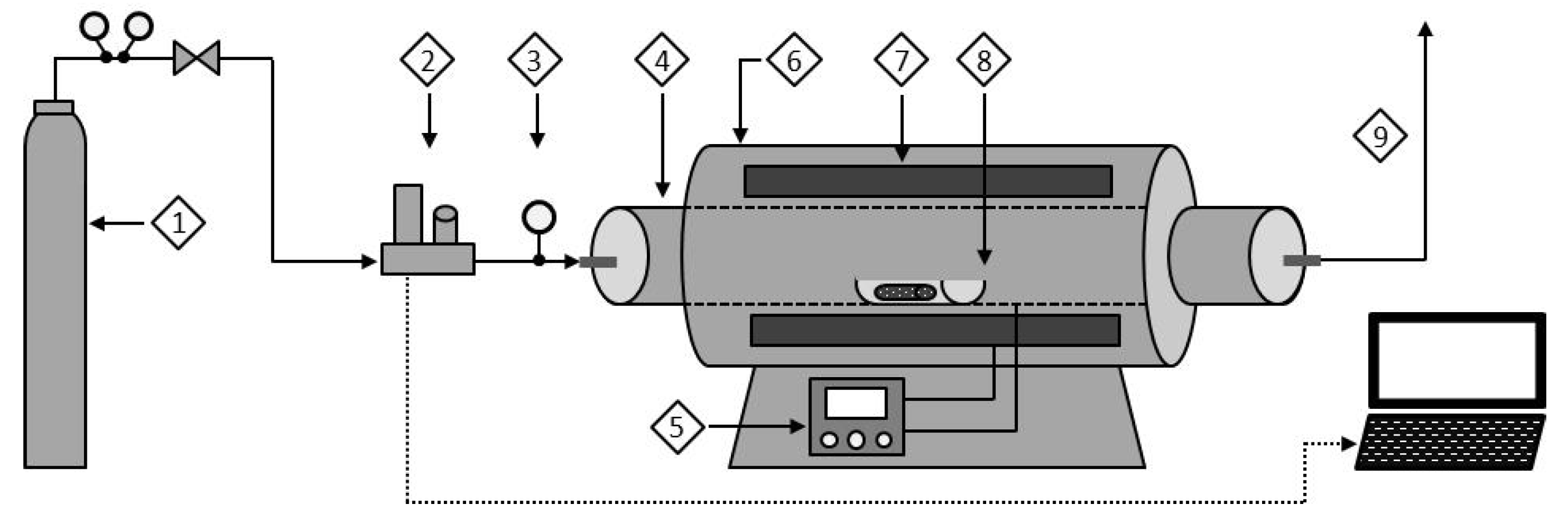
2.3. Evaluation of Permeation Properties of the Composite Carbon/Vycor® Membranes

Pore structure characteristics, gas permeation properties, and separation efficiency of the Carbon/Vycor® composite membranes were determined with the help of the following characterization procedures: (i) permeation measurements for water vapor; (ii) single-phase permeation measurements for various probe gases and a range of temperatures and feed pressures; and (iii) LN2 adsorption measurements.
The term ‘single-phase permeance’ refers to the permeance of one component, either pure gas or vapor. Depending on the magnitude of the pressure gradient applied across the membrane, single-phase gas permeation experiments are characterized either as integral or differential (for moderate/high and small pressure gradients respectively).
In this work, integral single-phase permeance measurements have been performed by applying pressure differences of 300 mbar or higher. The ratio of the permeance values of two single gases is referred to as ideal selectivity and the two particular gases are considered for a ‘gas pair’ (which is different from an actual binary gas mixture). To compare the experimental ideal selectivity of the single gases supplied to each studied membrane with the corresponding Knudsen ideal selectivity values, the permeance values of helium were chosen as a reference as helium is the gas with the smallest kinetic diameter, but also that which shows negligible adsorption even at ambient temperature.
Single-phase gas permeance and water vapor permeance measurements on the studied tubular Carbon/Vycor® membranes were conducted in a homemade laboratory stainless-steel permeability rig. The utilized laboratory apparatus and experimental methodology have been described elsewhere [56]. The SD value of the experimental method is ±2.3%. Table 3 presents the molar mass and kinetic diameter of the employed probe gases, derived from the literature [57,58,59,60,61]. Nitrogen adsorption isotherms at 77 Κ were obtained with a Quantachrome Autosorb-1 MP volumetric apparatus.

3. Results

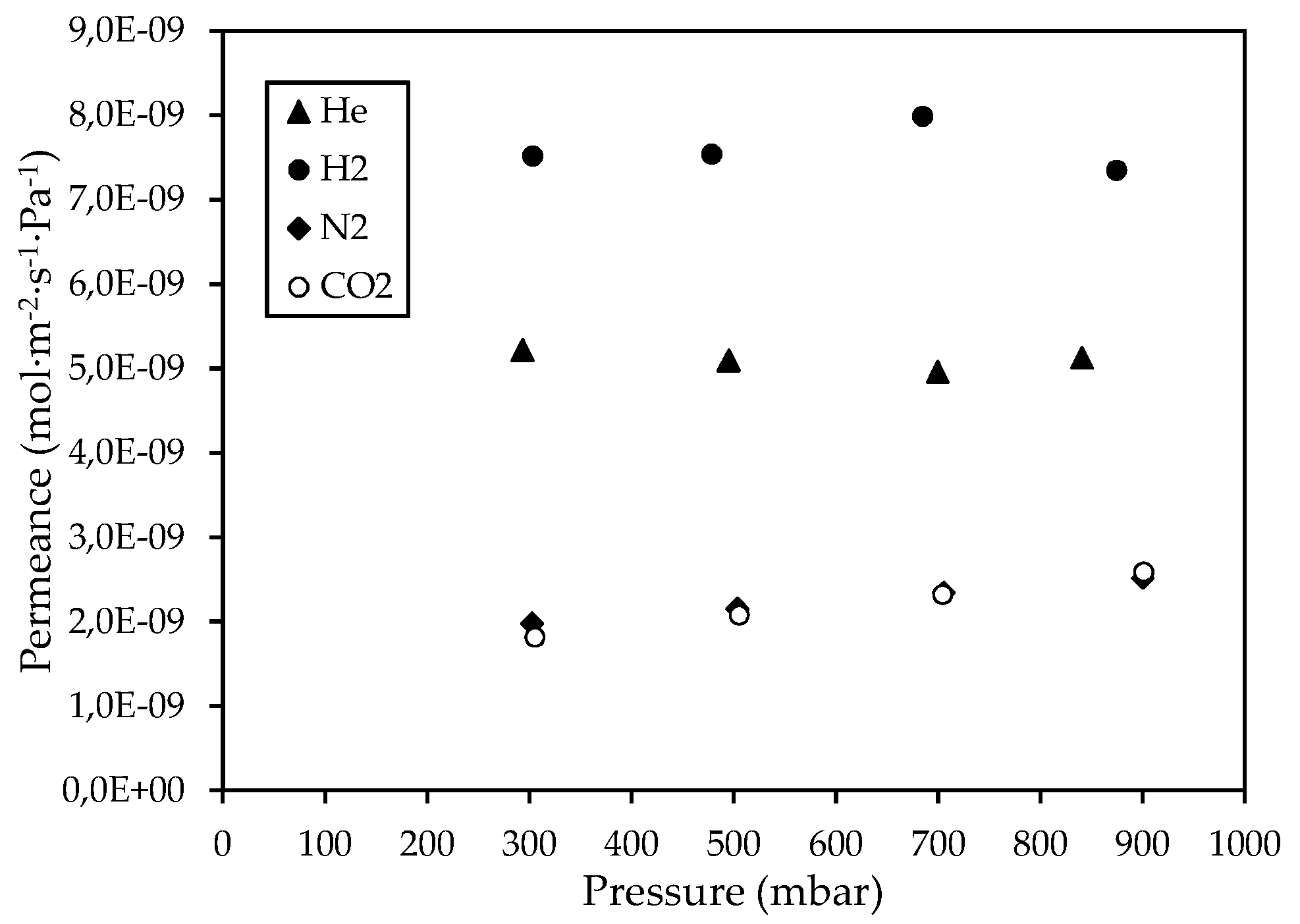
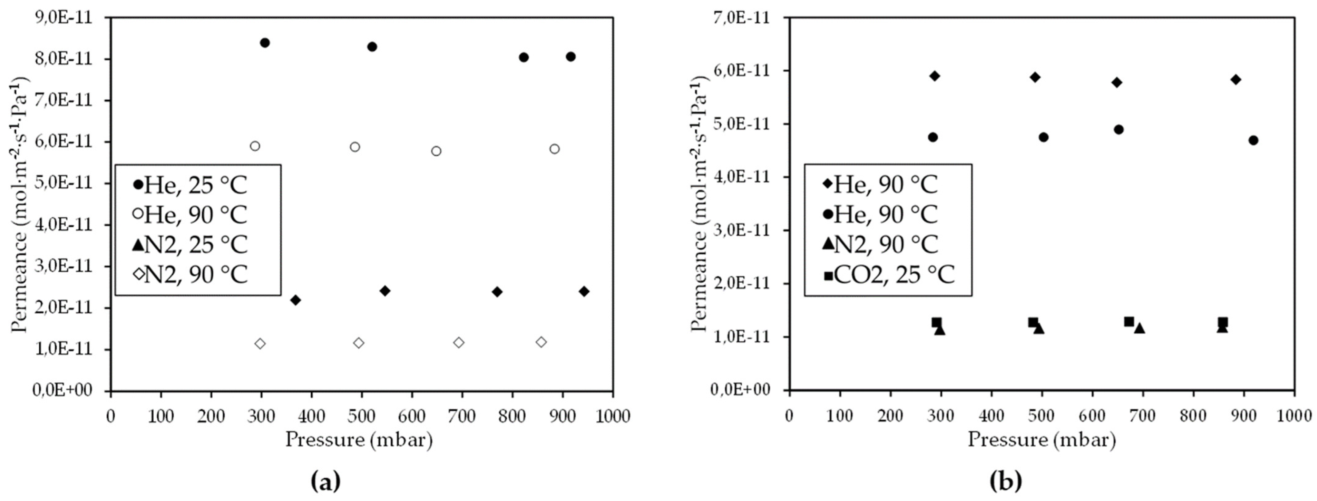
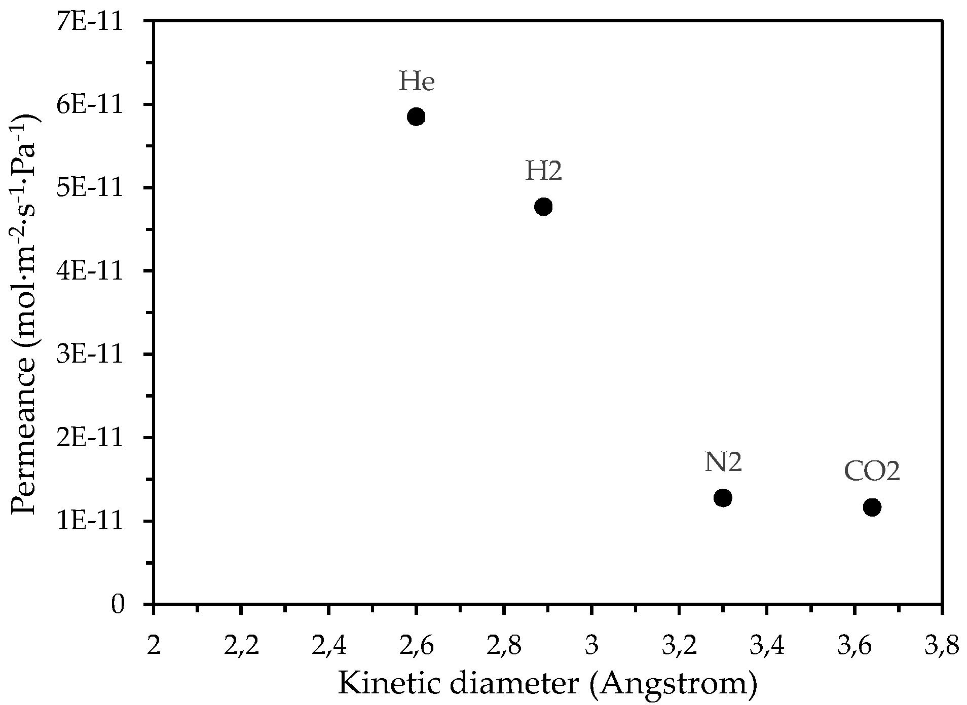
3.1. Gas Permeation Experimental Results

The gas permeation properties of the CM1 reference membrane, which was prepared by one impregnation/pyrolysis cycle, were studied by conducting single-phase gas permeance measurements at 25 °C and pressure gradients up to ~950 mbar; the results are presented in Figure 2.
Τhe obtained gas permeation results are indicative of the presence of mesoporous voids created between the interconnected carbon nanodomains that constituted the carbon phase inside the Vycor® pores. The presence of mesopores in the CM1 membrane was investigated by comparing the permeance ratio of each single probe gas with respect to helium, with the respective Knudsen ideal selectivity, at feed pressures of ~300 mbar. At this pressure, the ideal selectivity values for all gas pairs were larger than the respective ideal selectivities determined at the higher applied pressures. The results shown in Table 4 indicate that the transport mechanism of the probe gases through the CM1 membrane deviated from the Knudsen type of diffusion, according to which the gas permeance is independent of pressure.
The Knudsen diffusion of gases occurs within pores whose diameter (dp) is much smaller than the mean free path in the gas phase and the frequency of collisions of gas particles with the pore walls is much larger than that between each other. This is the case for mesopores which by definition correspond to the pore width range 2 nm < w < 50 nm). For a membrane with cylindrical mesopores, the following expression holds for the permeance by Knudsen diffusion, which is related to the porous structure parameters (porosity (ε), tortuosity (τ), and membrane thickness (l) [62]:
Q K = ε d p 3 τ l 8 π Μ R T 1 2
where M is the molar mass, R is the gas constant (=8.314 J mol−1 K−1), and T is the absolute temperature. Regarding a pair of two particular single gases, A and B, which both transport via Knudsen diffusion through a mesoporous barrier, from Equation (1), it ensues that
Q A Q B = M B M A
Equation (2) was used as a first approach to verify the diffusion mechanism of the probe gases through the developed membranes and therefore to make an estimation of their mean pore size. Based on the molar masses of Equation (2) a specific value is defined for the permeance ratio of two particular single gases, provided that they both permeate through a given mesoporous barrier exclusively via the Knudsen diffusion type at the same temperature. If the experimentally determined ideal selectivity, at a given temperature, coincides with the defined permeance ratio described above (known as the Knudsen ideal selectivity), the mechanism governing the transport of both gases is deduced to be of the Knudsen diffusion type, exclusively. The Knudsen type of diffusion is independent of the gas phase pressure and applied pressure gradient, as deduced by the mechanism’s definition and also as suggested by Equation (1).
Although the development of a completely microporous membrane was not achieved by the single cycle of impregnation/carbonization, the formation of a carbon phase within the pores of the Vycor® glass substrate reduced the permeance of He, N2, and CO2 single gases and increased the ideal selectivity of the CM1 membrane compared to the corresponding performance parameters of the Vycor® porous glass. Specifically, it has been reported that single-phase gas permeation experiments on pristine Vycor® substrates at 22 °C have shown a He permeation rate of 8.3 × 10⁻⁴ cm2 s−1 [63], while the He permeation rate for the CM1 membrane at 25 °C was 3.3 × 10⁻⁴ cm2 s−1.
Furthermore, the results shown in Figure 2 indicate that, in parallel with Knudsen diffusion through mesopores, an additional transport mechanism takes place, which contributes to the overall flow of N2, CO, CO2, C3H6, and C4H8 gases and (contrary to what characterizes Knudsen diffusion) is pressure dependent. This mechanism can be attributed to the surface diffusion of gases along the pore walls that arises from attractive interaction between the pores’ surface and gas molecules. As a result, a portion of gas molecules diffuses via successive sorption–desorption steps on adjacent adsorption sites of the pore surface (hopping model) in parallel with the portion of molecules that diffuse through collisions with the pore walls. The resulting surface coverage is amplified by increasing the gas phase pressure and this fact gradually leads to the formation of interfacial layers of gas molecules, which shift in the direction of flow, thereby contributing to the overall flow by acting additively on the transport via Knudsen diffusion. The mobility of these interfacial layers depends on the nature of the permeating gases, the membrane material and the applied gas pressure, pressure gradient, and temperature. Gases that interact strongly with the membrane material (and thus their molecules are more firmly bound onto the pore walls) tend to form less mobile adsorbed layers at lower and moderate temperatures whereas gases having a weaker interaction can form interfacial layers that transport with larger flow rates [64].
It can be observed that the permeance of C3H6 and C4H8 gases through the CM1 membrane is higher than that of CO2, although the molar mass of CO2 is approximately equal to the molar mass of C3H6 and less than that of C4H8. This finding can be attributed to the stronger interaction between dispersed nitrogen functional groups on the CM1 pore surface and the CO2 molecules, in comparison to the interaction with molecules of the two alkenes. It can be argued that the interaction between the alkene molecules and nitrogenous groups on the pore walls are weak π···π bonds, while in the respective case of CO2 adsorption, the interaction can include hydrogen bonds [65] and π-quadrupole moment interaction.
Besides the permeation experiments using the aforementioned probe gases, the single-phase permeance of water vapors through the CM1 membrane at 25 °C was measured at pressures of 4 and 14 mbar. In this case, the interaction with the nitrogen functional groups on the CM1 surface appeared to be stronger, thus highlighting the hydrophilic character of the membrane. Specifically, the water vapor permeance values through the CM1 membrane at the pressures of 4 and 14 mbar were 1.26 × 10⁻⁸ mol m−2 s−1 Pa−1 and 3.24 × 10⁻⁸ mol m−2 s−1 Pa−1, respectively, which were larger than the permeance values of all supplied gases. This finding indicates the presence of a mobile adsorbed phase on the pore walls, which flows and contributes to the total water vapor flow through the CM1. The adsorption mechanism of H2O molecules on carbonaceous materials is more complex than that of other common probe molecules, such as CO2, N2, and organic molecules. Hydrogen bonds and weak dipole–dipole interaction develop between water molecules and nitrogenous groups on the carbon surface. Once the first water molecules are adsorbed on active adsorption sites of the pore walls at low relative pressures, adsorbate–adsorbate interactions promote accumulation of further molecules with increasing vapor pressure, giving rise to the formation of water agglomerates [66,67].
The single-phase permeance measurements of He, H2, N2, and CO2 gases through the CM2 membrane at several pressures (Figure 3), have shown that the permeances of He, N2, and CO2 gases at 90 °C were reduced compared to the CM1 membrane. This can be attributed to the higher temperature of permeance measurements for CM2 than the temperature for CM1, thus reducing the contribution of surface diffusion to the total flow of N2 and CO2 gases. Nevertheless, at 25 °C, the N2 permeance for CM2 at a feed pressure of 1 bar was 3.67 × 10⁻⁹ mol m−2 s−1 Pa−1, whereas for CM1 the N2 permeance at 25 °C was 3.99 × 10⁻⁹ mol m−2 s−1 Pa−1, indicating a reduction of the mean pore size by applying a second cycle of impregnation/carbonization. However, as shown in Table 4, the experimental ideal selectivity values for the CM2, at a feed pressure of 300 mbar, approximated the corresponding ideal selectivities for Knudsen diffusion, thus suggesting that it was not possible to develop a microporous Carbon/Vycor® membrane by performing a second IL-infiltration step that lasted for 0.5 min.
In contrast, the ideal selectivities of the CM3 membrane for the gas pairs He/SF6, He/N2 and He/CO2, at a feed pressure of ~1 bar and 25 °C, exceeded the corresponding ideal selectivities for Knudsen diffusion (Table 4). Higher ideal selectivity values than those for Knudsen diffusion, at moderate or high temperatures and low pressures, especially when they pertain to non-adsorbable gases, indicate that the diffusion mechanism is that of microporous diffusion. In micropores, the kinetic diameter of gases is of decisive importance for their transport characteristics and permeation rates, especially when the pore width is less than twice their kinetic diameter [64].
The aforementioned trends for the CM3 membrane are compatible with a microporous membrane. Therefore, it can be proposed that by increasing the duration of the second impregnation to 1 min, the IL fills the gaps between the carbon nanodomains and forms a liquid film having a thickness such that growth of the microporous carbon structures could be achieved during the second carbonization treatment on the sample. Specifically, by increasing the time of the second impregnation by 0.5 min, the permeability of the Carbon/Vycor® membrane was drastically reduced by up to two orders of magnitude and this decline can be observed by comparing the plots of single-phase gas permeance vs. the pressure for membranes CM2 (Figure 3) and CM3 (Figure 4a).
Nevertheless, in addition to the microporous diffusion mechanism (permeation dependence on the gas kinetic diameter), it seems that the surface diffusion mechanism (transport of mobile layers of adsorbed N2, CO2, and SF6 molecules along the pore walls) also contributes to the total gas flow through the CM3 membrane. The contribution of surface diffusion appears to be more pronounced for the transport of CO2 through the CM3 in relation to CM2, mainly due to the lower membrane temperature.
To further investigate the dependence of CO2 surface diffusion on the temperature and pressure in CM3 membrane, additional single-phase permeance measurements of CO2 were performed at higher pressures and three temperatures (25, 50, and 90 °C). The CO2 permeance as a function of pressure is presented in Figure 4b. As can be observed, CO2 permeance through CM3 at 25 °C increased with increasing feed pressure, indicating an enhanced contribution from surface diffusion to the total CO2 transport. On the contrary, at higher temperatures (50 and 90 °C), CO2 permeance in the CM3 was reduced and remained constant throughout the applied pressure range, due to a substantial reduction in the pore surface coverage from the adsorbed CO2 phase, which diminished the contribution of surface diffusion to the total CO2 flow through CM3.
Furthermore, as the temperature increased from 25 °C to 90 °C, He and N2 permeance through the CM3 membrane was reduced, as shown in Figure 5a. For both He and N2, this reduction can be attributed to the dominance of the Knudsen diffusion type, wherein the gas permeance is inversely proportional to temperature [64]. In any case, the mean ideal selectivity values (with respect to Helium) over the entire pressure range for the CM3 at 90 °C were higher than the corresponding Knudsen ideal selectivities and higher than the respective ones at 25 °C (Table 4). A drastic reduction in permeance of He, N2, and CO2 gases at 90 °C by almost two orders of magnitude has also occurred in the case of the CM3 membrane with regard to their permeation through the CM2 membrane, as shown in the results presented in Figure 3 (for CM2) and Figure 5b (for CM3). In addition, from the results derived at 90 °C for the CM3 (Figure 5b), it is evident that for all applied pressures, the permeance of the supplied probe gases depended on their kinetic diameter (Figure 6), thus indicating that gas diffusion takes place primarily through the microporous carbon film formed on the outer side of the CM3 membrane.
To further study the permeation properties evolution of the Carbon/Vycor® membranes as a function of the duration of the second impregnation step, two additional membranes, CM4 and CM5, were prepared, for which the second infiltration step lasted for 1.5 and 3 min, respectively (Table 2). According to the gas permeation results of the CM4 and CM5 membranes, it appears that the diffusion of the supplied probe gases did not take place through a microporous material (Figure 7a). Specifically, for the diffusion of He, N2, CO2, C3H6, C4H8, and SF6 gases through the CM4, the mean values of ideal selectivity with respect to helium were identical to, or less than, the root of the inverse molar mass ratio over the entire pressure range (Εquation (2)). In addition, the mean ideal selectivity values were substantially lower than those determined for the CM3 membrane (Table 4).
As in the case of the CM1 membrane, there was a strong contribution of surface diffusion to the total permeance of C3H6 and C4H8 gases that exceeded the permeance of N2, CO2, and SF6 gases. In addition, the pressure dependence of He, N2, CO2, and SF6 permeation through the CM4 at higher temperatures was investigated and the results are depicted in Figure 7b. As can be noticed, the permeances of the N2, CO2, and SF6 gases were reduced with rising temperature due to mitigation of the contribution of surface diffusion to the total gas flow through the membrane pores. From Equation (1), it also ensues that when Knudsen diffusion is the dominant transport mechanism, the permeance is proportional to the inverse square root of the absolute temperature.
According to the gas permeance results for CM5 (Table 5), it seems that gas transport is carried out through a mesoporous material. Table 5 shows the mean ideal selectivities for the pairs of H2, N2, and CO2 with helium at 100 °C, for the CM5 membrane, determined over the entire experimental pressure range, in comparison to the corresponding Knudsen ideal selectivities. In particular, for the CM5 membrane, it appears that as the feed pressure increased, a transition onset from the Knudsen-type diffusion to viscous flow had occurred (as observed for He and CH4 gases in Figure 8a). When the pore size is considerably larger than the mean free path of the gas molecules an additional flow component is added to the total gas flow, owing to the pressure difference at the pore ends. For cylindrical pores and non-adsorbable gases this additional macroscopic laminar flow (Poiseuille flow) can be described by the following equation [68]:
Q = P π r c 2 8 μ L
where Q is the gas permeance, P is the pressure, rc is the capillary radius, L is the length of the capillary, and μ is the dynamic viscosity.
As can be noticed from Equation (3), the contribution of the Poiseuille flow to the total gas flow becomes greater as the pressure and pore size increase, due to the increasing frequency of the molecular collisions in the gas phase, while with increasing temperature the viscosity of the gas phase increases (μT1/2), thereby reducing the barrier’s permeability. However, in the case of mesopores or in the area of low or almost zero pressures, the mean free path of the molecules may become comparable to or larger than the diameter of the pores. As a result, the collisions of the molecules with the walls are more frequent than the molecular collisions.
In the Knudsen diffusion regime, the radius of the pores is much smaller than the mean free path of the gas (rc/λ → 0), and as a consequence, each gas molecule permeating through the porous network moves independently from the others. As the mean pressure increases (decrease in λ), a transition occurs from the Knudsen diffusion region (permeance is independent of the mean pressure) to the viscous flow region (permeance is proportional to the average pressure). For the transition from the Knudsen-type diffusion to the viscous flow, a simple relation was found that connects the mean free path of the gas with the mean pore radius (r) and enables to calculate the value of the pressure for which this transition occurs [68]:
0.05 < r λ < 50
For the CM5 membrane, an increase in He permeance at 100 °C starting from the pressure of 730 mbar was found; according to Equation (4), this value corresponds to a pore radius of 47 < r < 235 Å. Therefore, the increase in N2 and CO2 permeance through the CM5 with increasing pressure can be attributed both to the transition from the Knudsen diffusion type to the Poiseuille flow and to the additional contribution of the surface diffusion to the total gas flow. This particular dependence of permeance on the feed pressure is maintained at greater pressures, as shown in Figure 8b, which presents N2 and CO2 permeance through CM5 as a function of the applied feed pressure.
Summarizing the evaluation results of the gas separation efficiency of the developed membranes (Figure 9), it may become apparent that it is possible to fine-tune the optimum impregnation time within the range of 0.5 to 1 min and achieve the fabrication of a purely microporous Carbon/Vycor® membrane.
As can be seen in Figure 9, by increasing the time of the second impregnation step from 0.5 to 1 min (CM3), the permeation of Helium decreases, as a result of narrowing of the membrane pores by the growth of carbon particles within the Vycor® porous network. Nevertheless, with a further increase in the second impregnation step duration (CM4 and CM5) the helium permeance increases to an extent that it exceeds the respective permeance of the composite membrane developed through one single impregnation/carbonation cycle. This fact can be attributed to the development of defects due to the fatigue of the membranes CM4Μ_4 and CM5. The main reasons are the large amount of IL entrapped into the pore structure of the Vycor® tubes along with structural alterations of the Vycor® substrate itself due to the high carbonization temperature and the repeated cycles of heat treatment. Explanatively, the high amount of IL in conjunction with the high penetration depth restricts the free escape of volatile by-products during carbonization. As a result, the substrate may be subjected to high stresses that degrade its structural integrity. Furthermore, despite that the glass transition temperature of Vycor® being 1000 °C, structural changes may occur at lower temperatures (800 °C) both because the Vycor® configuration changes after the first cycle of carbon film formation as well as because the entrapped IL may act as fuel material, which reduces the temperature of the thermal decomposition of Vycor® and augments its thermal decomposition kinetics (see also Section 3.2). Hence, in the case of CM5, the presence of pores with a size of 47 < r < 235 Å can be attributed to the presence of defects in the composite membrane, which are of larger dimensions than the pores of the Vycor® glass substrate.
Nevertheless, as mentioned above, the targets set when developing carbon membranes for gas separations are either the development of CMSMs with a pore size between 3 and 5 Å or the preparation of selective microporous barriers (ASCMs, Adsorption-selective carbon membranes), with a pore size between 5 and 7 Å and selective mesoporous membranes with a high concentration of active adsorption sites [69,70]. In the first case, the separation mechanism is that of exclusion due to the comparison to the molecular dimensions pore size, while in adsorption-selective membranes, an additional component (surface diffusion) contributes to the total flow of gases [71]. For this purpose, adsorption-selective membranes are mainly used to separate non-interacting or weakly adsorbable gases (such as O2, N2, and CH4) from adsorbable ones (such as CO2, NH3, SO2, and H2S).
In this work, as demonstrated by the single-phase permeation experiments, the developed membrane that exhibited size exclusion characteristics owing to its microporous structure was CM3. Although CM3 provided much lower ideal selectivity values (as derived from the mean values for all applied pressures) for the gas pairs N2/SF6 (2.16 at 25 °C), H2/N2 (4.1 at 90 °C), He/N2 (3.36 and 5.02 at 25 °C and 90 °C respectively), and He/SF6 (7.33 at 90 °C) compared to the corresponding selectivities of the microporous carbon membrane reported in the literature (N2/SF6 ~ 4, H2/N2 from 10 to 20 and He/N2 and He/SF6 from 20 to 40) [71], the CM3 membrane achieved a remarkable ideal He/CO2 selectivity (Figure 9a) (namely, 4.31 at 1 bar pressure and 25 °C and 4.64 for pressure ~300 mbar at 90 °C), which exceeds the corresponding selectivity provided by other microporous carbon barriers reported in the literature (~4) [71,72].
Regarding the developed mesoporous membranes, as can be observed in Figure 9b, by increasing the duration of the second impregnation step, the CO2/N2 ideal selectivity was slightly enhanced. This trend can be ascribed to an increasing population of active adsorption sites on the carbon surface by extending the impregnation of [BMIM] [TCM] IL. In fact, CO2 permeation has been reported to augment with increasing population of the nitrogen functional groups on the carbon membranes surface, thereby increasing their CO2/N2 selectivity. Specifically, the highest CO2/N2 ideal selectivity (1.86) was provided by the CM5 for a pressure of 1 bar at 100 °C. This specific value of the CM5 membrane falls within or even exceeds the range of CO2/N2 ideal selectivity values achieved by other N-doped micro-mesoporous carbon membranes (having pore size within the pore size range of CM5), which have been reported in the literature [70].

3.2. Elucidation of the Porous Structure of Carbon/Vycor® Membranes by Performing N2 Adsorption Isotherms at 77K

The evolution of the porous structure characteristics of the developed membranes with extending the second impregnation step was further studied through N2 (77 K) adsorption measurements, which were performed on the developed CM1, CM4, and CM6 membranes. Figure 10 shows the LN2 adsorption isotherms of the three membranes along with the PSD curves extracted from the adsorption and desorption branches of their adsorption isotherms. All isotherms are of type IV with a type H2 hysteresis loop, which tends to approach type H1 as the infiltration stage as the second cycle is being prolonged (Figure 10a); this finding is, in general, compatible with enhanced pore size uniformity. Hysteresis loops of type H1 are given by a variety of mesoporous glasses and ordered mesoporous materials. Such pore structures can be regarded as virtually rigid and the corresponding adsorption isotherm have a well-defined plateau at high vapor relative pressures. This hysteresis arises from capillary condensation that is delayed due to the existence of metastable adsorption fluid in the adsorption branch, while evaporation occurs via equilibrium from an open pore. The type H2 hysteresis loops present a wide and asymmetrical shape with a steeper evaporation branch, which arise from a broad PSD. Hysteresis loops of type H2 can imply the presence of pores with a constriction (or neck), the so-called ink-bottle pores, or an assembly of cavities connected by constrictions. According to the pore-blocking model, the wider pore segment can empty only when the constriction empties. Thus, the evaporation pressure of the wider pore segment does not depend on its size but only on the size of the constriction; as a result, the liquid condensate evaporation is delayed (in terms of P/Po) with regard to the condensation, giving rise to a hysteresis phenomenon. Moreover, it has been proposed that any variation in the fluid/wall interaction along the pore (variations in pore size or shape, in the chemical nature of the surface, etc.) can produce a hysteresis loop of H2 type [73].
The PSD curve of the CM1 desorption branch showed a bimodal peak within the mesopore size range, which in the case of the CM4 and CM6 membranes turned into a single peak (Figure 10b–d).
However, the width of this single peak expanded towards smaller and larger pore size directions upon application of a second impregnation/carbonization cycle, to an extent that it exceeded the upper and lower pore size limit of the pristine Vycor® substrate. Furthermore, by prolonging the second impregnation step, the upper size limit for the carbon phase mesopores was increased. In view of the involved pore size distributions produced, it might be safer to emphasize loss of bimodality rather than enhancement of uniformity for longer second impregnation steps.
The Brunauer–Emmett–Teller (BET) method was applied to determine the BET surface area (SBET) and the adsorbent monolayer capacity (Vm) of membranes CM1, CM4, and CM6. The volume of mesopores (Vmeso) and their size distribution (PSD) was obtained by applying the Barrett–Joyner–Halenda (BJH) analysis to the isotherm desorption branch. Moreover, Vmeso was estimated by the difference between the adsorbed volume at P/Po = 0.97 (i.e., V0.97 ≡ Vp,t, total pore volume) and the total volume of micropores of the studied membranes (i.e., Vp,t −Vmicro). The results obtained from the pore structure analysis of the three samples are presented in Table 6.
According to the results shown in Table 2, the SBET values of the studied composite membranes are either similar to or lower than the SBET (=176.75 m2 g−1) of the untreated Vycor® glass. An increase in SBET relative to the pristine Vycor® might suggest a larger amount of carbon, which contributes not only because the carbonate material itself has a microporous structure but also because the voids between the carbonate material and Vycor® were significantly reduced. It seems that application of a second IL-infiltration step for a period of 1.5 min resulted in slight reduction in both microporous and total membrane porosity, compared to the case where no second impregnation/carbonization cycle was applied, and the case where the second cycle of treatment lasted for 2 min. The volume of the mesopores also decreases with respect to the pristine Vycor® glass (Vp,t = 0.228 cm3 g−1), and the ascent during adsorption occurs in large P/Po. This finding could indicate that some of the small necks of the Carbon/Vycor® membranes pores are completely blocked, and this can affect the shape of the desorption branch.

4. Discussion

Overall, longer second impregnation steps appear to lead to both an enhancement of the microporous carbon part and the formation of some broader mesopores at the same time. Optimization of the duration of the second impregnation step is very sensitive to system details; as a matter of fact, even for simple porous carbon membranes the creation of defects (that might be related in our case to the enhancement of mesopores) is a rather common complication in the development of carbon membranes [71]. Studies of fluid imbibition into porous inorganic membranes have utilized simplified mathematical models that relied on a number of assumptions, while the extent of IL infiltration into porous ceramic membranes has not been reported to be linearly dependent on time [58].
Specifically, the kinetics of IL imbibition in porous inorganic substrates depends on the contact angle between the ILs and the pore walls. The value of this contact angle is a function of both the magnitude of the hydrophilicity/hydrophobicity of the IL/substrate system and the porous structure of the solid material (mean pore size, pore size distribution, tortuosity). However, the porous structure characteristics may be altered in the direction of the liquid flow, due to possible drifting (or entrapment) of particles from the wetted parts of the pores towards empty pore segments of the solid substrate [74].
Regarding the carbonization stage, the chemical and structural changes taking place during the thermal degradation of the supported IL phase seem to proceed in synergy with the structural alterations of the Vycor® substrate during the heat treatment of the SILM membrane, thereby decisively affecting the final configuration of the Carbon/Vycor® membrane porous structure. In particular, although the substrate used to develop the studied composite membranes is distinguished by its thermal stability at high temperatures, alterations in the substrate’s porous structure would likely begin to occur above 850 °C. In particular, although the heating of Vycor® glass up to 850 °C does not bring about significant changes regarding pore volume and specific surface area, it results in an overall reduction of the pore size (including both narrower and wider pores), whereas above 1000 °C the pore size increases as the specific glass begins to soften (maximum operating temperature: 900 °C). Of course, the glass transition temperature (Tg) of ceramic materials decreases steadily with the pore size, while it depends on the type of material and configuration of the area (free liquid film or area constrained into pores, etc.). In the case of our composite Carbon/Vycor® membranes, except for the variation in the size of the solid segments (due to variations in the size of the pores), the Vycor® configuration changes after the first cycle of carbon film formation processes, possibly resulting in the lowering of Tg and the modification of the porous structure of Vycor® even at a carbonization temperature of 800 °C.
Along with the structural alterations of the substrate at such elevated temperatures, the [BMIM][TCM] IL might also have acted as an anionic surfactant in the catalytic thermal degradation of the substrate, resulting in expansion of its pores. Relatively, ILs have already been studied as alternative surfactants for a variety of applications (as anti-corrosion agents, as asphaltene precipitate inhibitors, as a means of separating organic pollutants from aqueous solutions, etc.) [75], while, as has been reported, in the field of ceramic porous materials the surfactants with increasing temperature act as fuel material, thereby reducing the temperature of thermal decomposition of ceramic materials and augmenting their thermal decomposition kinetics [76].

5. Conclusions

In this work, Vycor®/IL membranes were prepared by vacuum-assisted infiltration of Vycor® mesoporous glass tubes with the ionic liquid 1-methyl-3-butylimidazolium tricyanomethanide. Subsequently, the Vycor®/IL membrane precursors were subjected to inert-atmosphere pyrolysis at 800 °C for 2 h in order to attain carbonization of the infiltrated IL phase. Furthermore, a second cycle of vacuum-assisted infiltration (using the same IL) and subsequent pyrolysis followed and the effect of the duration of the second filtration for the (0.5 min, 3 min) range was probed.
The evolution of the porous structure, as well as the gas permeation properties and separation efficiency of the composite Carbon/Vycor® membranes, were studied by conducting single-phase gas permeation experiments and LN2 adsorption measurements. Τhe gas permeation results indicated the creation of mesoporous voids between interconnected carbon nanodomains inside the pores of the Vycor® substrate when a single infiltration/pyrolysis cycle was conducted. The carbonaceous phase showed stronger interaction with CO2 molecules compared to the other supplied probe gases owing to the nitrogen functional groups present on the carbon surface. The single-phase permeation experiments of water vapors through the membrane demonstrated their strong interaction with the nitrogen groups on the carbon surface, thus highlighting the hydrophilic character of the membrane.
Application of a second infiltration/pyrolysis cycle, where the new infiltration step was carried out for 0.5 min, did not make it possible to develop a microporous Carbon/Vycor® membrane although a reduction in the mean pore size was indicated by the gas permeance measurements. By increasing the duration of the second impregnation step to 1 min, the IL was able to fill the gaps between the carbon domains and form a liquid separation film on the outer side of the carbon phase of suitable thickness so that growth of microporous carbon structures could be achieved during the following carbonization step. The gas permeation experiments revealed that the probe gases diffused through a microporous Carbon/Vycor® membrane, as suggested by the dependence of their permeance on the gas kinetic diameter (a distinguishing feature of the microporous diffusion mechanism) and the drastic reduction in their permeance by up to two orders of magnitude. Infiltration for longer times (1.5 min and 3 min) led to inferior products.
Τhe present study led to the fabrication of a microporous membrane that relies on the collaboration of porous carbon and porous silica and exhibited size-exclusion characteristics. The achieved ideal He/CO2 selectivity values of 4.31 at 1 bar pressure and 25 °C and 4.64 for pressure~300 mbar at 90 °C are notable. The CO2/N2 ideal selectivity becomes slightly enhanced upon prolongation of the second impregnation step with the [BMIM][TCM] IL, as a consequence of an increasing concentration of nitrogen-containing adsorption sites with a strong affinity towards CO2 on the carbon surface.
The identification of optimal treatment procedures and conditions for porous silica substrates impregnated with ionic liquids can make a decisive contribution toward improving the permeability and separation efficiency of supported porous carbon membranes with molecular sieve characteristics. Separation capacity will depend on the geometrical features of the carbon network and the surface physical chemistry of the pores; both latter features can be different for different ILs and exploration of the results possible upon employment of other ILs will be the subject of future research.

Author Contributions

Conceptualization, G.R. and K.G.B.; methodology, G.R. and O.T.; investigation, O.T.; resources, G.P. and G.R.; writing-original draft preparation, A.L.; writing-review and editing, A.L., G.R. and K.G.B.; supervision, G.R. and K.G.B. All authors have read and agreed to the published version of the manuscript.

Funding

This research received no external funding.

Institutional Review Board Statement

Not applicable.

Informed Consent Statement

Not applicable.

Data Availability Statement

Not applicable.

Acknowledgments

IoLiTech GmbH is kindly acknowledged for providing the 1-methyl-3-butylimidazolium tricyanomethanide ionic liquid.

Conflicts of Interest

The authors declare no conflict of interest.

References

  1. Burggraaf, A.J. General overview, trends and proscpects. In Fundamentals of Inorganic Membrane Science and Technology; Burggraaf, A.J., Cot, L., Eds.; Membrane Science and Technology Series #4; Elsevier Science B.V.: Amsterdam, The Netherlands, 1996; Chapter 1; pp. 1–20. [Google Scholar]
  2. Leimert, J.M.; Karl, J.; Dillig, M. Dry reforming of methane using a nickel membrane reactor. Processes 2017, 5, 82. [Google Scholar] [CrossRef]
  3. Paturzo, L.; Gallucci, F.; Basile, A.; Vitulli, G.; Pertici, P. An Ru-based catalytic membrane reactor for dry reforming of methane—Its catalytic performance compared with tubular packed bed reactors. Catal. Today 2003, 82, 57–65. [Google Scholar] [CrossRef]
  4. Uhlhorn, R.J.R.; Keizer, K.; Burggraaf, A.J. Gas transport and separation with ceramic membranes. Part II. Synthesis and separation properties of microporous membranes. J. Membr. Sci. 1992, 66, 271–287. [Google Scholar] [CrossRef]
  5. Zhang, D.Q.; Zhou, S.Y.; Fan, Y.Q.; Xu, N.P.; He, Y.H. Preparation of dense Pd composite membranes on porous Ti-Al alloy support by electroless plating. J. Membr. Sci. 2012, 387–388, 24–29. [Google Scholar] [CrossRef]
  6. Hashim, S.S.; Mohamed, A.R.; Bhatia, S. Oxygen separation from air using ceramic-based membrane technology for sustainable fuel production and power generation. Renew. Sustain. Energy Rev. 2011, 15, 1284–1293. [Google Scholar] [CrossRef]
  7. Merritt, A.; Rajagopalan, R.; Foley, H.C. High performance nanoporous carbon membranes for air separation. Carbon 2007, 45, 1267–1278. [Google Scholar] [CrossRef]
  8. Adewole, J.K.; Ahmad, A.L.; Ismail, S.; Leo, C.P. Current challenges in membrane separation of CO2 from natural gas: A review. Int. J. Greenhouse Gas Control 2013, 17, 46–65. [Google Scholar] [CrossRef]
  9. Baker, R.W.; Lokhandwala, K. Natural gas processing with membranes: An overview. Ind. Eng. Chem. Res. 2008, 47, 2109–2121. [Google Scholar] [CrossRef]
  10. Baena-Moreno, F.M.; Le Saché, E.; Pastor-Pérez, L.; Reina, T.R. Membrane-based technologies for biogas upgrading: A review. Environ. Chem. Lett. 2020, 18, 1649–1658. [Google Scholar] [CrossRef]
  11. Baker, R.W.; Freeman, B.; Kniep, J.; Wei, X.; Merkel, T. CO2 capture from natural gas power plants using selective exhaust gas recycle membrane designs. Int. J. Greenh. Gas Control. 2017, 66, 35–47. [Google Scholar] [CrossRef]
  12. Powell, C.E.; Qiao, G.G. Polymeric CO2/N2 gas separation membranes for the capture of carbon dioxide from power plant flue gases. J. Membr. Sci. 2006, 279, 1–49. [Google Scholar] [CrossRef]
  13. Ku, A.Y.; Kulkarni, P.; Shisler, R.; Wei, W. Membrane performance requirements for carbon dioxide capture using hydrogen-selective membranes in integrated gasification combined cycle (IGCC) power plants. J. Membr. Sci. 2011, 367, 233–239. [Google Scholar] [CrossRef]
  14. Stoitsas, K.A.; Gotzias, A.; Kikkinides, E.S.; Steriotis, T.A.; Kanellopoulos, N.K.; Stoukides, M.; Zaspalis, V.T. Porous ceramic membranes for propane–propylene separation via the π-complexation mechanism: Unsupported systems. Micropor. Mesopor. Mater. 2005, 78, 235–243. [Google Scholar] [CrossRef]
  15. Labropoulos, A.I.; Athanasekou, C.P.; Kakizis, N.K.; Sapalidis, A.A.; Pilatos, G.I.; Romanos, G.E.; Kanellopoulos, N.K. Experimental investigation of the transport mechanism of several gases during the CVD post-treatment of nanoporous membranes. Chem. Eng. J. 2014, 255, 377–393. [Google Scholar] [CrossRef]
  16. Romanos, G.E.; Athanasekou, C.P.; Katsaros, F.K.; Kanellopoulos, N.K.; Dionysiou, D.D.; Likodimos, V.; Falaras, P. Double-side active TiO2-modified nanofiltration membranes in continuous flow photocatalytic reactors for effective water purification. J. Hazard. Mater. 2012, 211–212, 304–316. [Google Scholar] [CrossRef]
  17. Hayashi, J.I.; Yamamoto, M.; Kusakabe, K.; Morooka, S. Effect of oxidation on gas permeation of carbon molecular sieving membranes based on BPDA-pp‘ODA polyimide. Ind. Eng. Chem. Res. 1997, 36, 2134–2140. [Google Scholar] [CrossRef]
  18. Kocherginsky, N.M.; Yang, Q.; Seelam, L. Recent advances in supported liquid membrane technology. Separ. Purif. Techn. 2007, 53, 171–177. [Google Scholar] [CrossRef]
  19. de los Rios, A.P.; Hernandez-Fernandez, F.J.; Tomas-Alonso, F.; Palacios, J.M.; Gomez, D.; Rubio, M.; Villora, G. A SEM-EDX study of highly stable supported liquid membranes based on ionic liquids. J. Membr. Sci. 2007, 300, 88–94. [Google Scholar] [CrossRef]
  20. Tzialla, O.; Labropoulos, A.; Panou, A.; Sanopoulou, M.; Kouvelos, E.; Athanasekou, C.; Beltsios, K.; Likodimos, V.; Falaras, P.; Romanos, G. Phase behavior and permeability of Alkyl-Methyl-Imidazolium Tricyanomethanide ionic liquids supported in nanoporous membranes. Sep. Purif. Technol. 2014, 135, 22–34. [Google Scholar] [CrossRef]
  21. Karousos, D.S.; Labropoulos, A.I.; Sapalidis, A.; Kanellopoulos, N.K.; Iliev, B.; Schubert, T.J.S.; Romanos, G.E. Nanoporous ceramic supported ionic liquid membranes for CO2 and SO2 removal from flue gas. Chem. Eng. J. 2017, 313, 777–790. [Google Scholar] [CrossRef]
  22. Tzialla, O.; Veziri, C.; Papatryfon, X.; Beltsios, K.G.; Labropoulos, A.; Iliev, B.; Adamova, G.; Schubert, T.J.S.; Kroon, M.C.; Francisco, M.; et al. Zeolite imidazolate framework—Ionic liquid hybrid membranes for highly selective CO2 separation. J. Phys. Chem. C 2013, 117, 18434–18440. [Google Scholar] [CrossRef]
  23. Friess, K.; Izák, P.; Kárászová, M.; Pasichnyk, M.; Lanč, M.; Nikolaeva, D.; Luis, P.; Jansen, J.C. A review on ionic liquid gas separation membranes. Membranes 2021, 11, 97. [Google Scholar] [CrossRef] [PubMed]
  24. Romanos, G.E.; Vangeli, O.C.; Stefanopoulos, K.L.; Kouvelos, E.P.; Papageorgiou, S.K.; Favvas, E.P.; Kanellopoulos, N.K. Methods of evaluating pore morphology in hybrid organic–inorganic porous materials. Micropor. Mesopor. Mater. 2009, 120, 53–61. [Google Scholar] [CrossRef]
  25. Lei, Z.; Dai, C.; Chen, B. Gas solubility in ionic liquids. Chem. Rev. 2014, 114, 1289–1326. [Google Scholar] [CrossRef]
  26. Ramdin, M.; de Loos, T.W.; Vlugt, T.J.H. State-of-the-art of CO2 capture with ionic liquids. Ind. Eng. Chem. Res. 2012, 51, 8149–8177. [Google Scholar] [CrossRef]
  27. Cui, G.; Zheng, J.; Luo, X.; Lin, W.; Ding, F.; Li, H.; Wang, C. Tuning anion-functionalized ionic liquids for improved SO2 capture. Angew. Chem. Int. Ed. 2013, 52, 10620–10624. [Google Scholar] [CrossRef]
  28. Steel, K.M.; Koros, W.J. An investigation of the effects of pyrolysis parameters on gas separation properties of carbon materials. Carbon 2005, 43, 1843–1856. [Google Scholar] [CrossRef]
  29. Favvas, E.P.; Kouvelos, E.P.; Romanos, G.E.; Pilatos, G.I.; Mitropoulos, A.C.; Kanellopoulos, N.K. Characterization of highly selective microporous carbon hollow fiber membranes prepared from a commercial co-polyimide precursor. J. Porous Mater. 2008, 15, 625–633. [Google Scholar] [CrossRef]
  30. Foley, H.C. Carbogenic molecular sieves: Synthesis, properties and applications. Micropor. Mater. 1995, 4, 407–433. [Google Scholar] [CrossRef]
  31. Kim, S.-J.; Kwon, Y.; Kim, D.; Park, H.; Cho, Y.H.; Nam, S.-E.; Park, Y.-I. A review on polymer precursors of carbon molecular sieve membranes for olefin/paraffin separation. Membranes 2021, 11, 482. [Google Scholar] [CrossRef]
  32. Salleh, W.N.W.; Ismail, A.F. Carbon membranes for gas separation processes: Recent progress and future perspective. J. Membr. Sci. Res. 2015, 1, 2–15. [Google Scholar]
  33. Vu, D.Q.; Koros, W.J.; Miller, S.J. High pressure CO2/CH4 separation using carbon molecular sieve hollow fiber membranes. Ind. Eng. Chem. Res. 2002, 41, 367–380. [Google Scholar] [CrossRef]
  34. Chu, Y.; He, X. Process simulation and cost evaluation of carbon membranes for CO2 removal from high-pressure natural gas. Membranes 2018, 8, 118. [Google Scholar] [CrossRef] [PubMed]
  35. Tseng, H.-H.; Shih, K.; Shiu, P.-T.; Wey, M.-Y. Influence of support structure on the permeation behavior of polyetherimide-derived carbon molecular sieve composite membrane. J. Membr. Sci. 2012, 405–406, 250–260. [Google Scholar] [CrossRef]
  36. Centeno, T.A.; Fuertes, A.B. Supported carbon molecular sieve membranes based on a phenolic resin. J. Membr. Sci. 1999, 160, 201–211. [Google Scholar] [CrossRef]
  37. Rajagopalan, R.; Foley, H.C. Study of the effect of morphology of nanoporous carbon membranes on permselectivity. Mater. Res. Soc. Symp.-Proc. 2003, 752, 225–230. [Google Scholar] [CrossRef]
  38. Ismail, N.H.; Salleh, W.N.W.; Sazali, N.; Ismail, A.F.; Yusof, N.; Aziz, F. Disk supported carbon membrane via spray coating method: Effect of carbonization temperature and atmosphere. Separ. Purif. Techn. 2018, 195, 295–304. [Google Scholar] [CrossRef]
  39. Wang, H.; Zhang, L.; Gavalas, G.R. Preparation of supported carbon membranes from furfuryl alcohol by vapor deposition polymerization. J. Membr. Sci. 2000, 177, 25–31. [Google Scholar] [CrossRef]
  40. Pels, J.R.; Kapteijn, F.; Moulijn, J.A.; Zhu, Q.; Thomas, K.M. Evolution of Nitrogen functionalities in carbonaceous materials during pyrolysis. Carbon 1995, 33, 1641–1653. [Google Scholar] [CrossRef]
  41. Sevilla, M.; Valle-Vigón, P.; Fuertes, A.B. N-doped polypyrrole-based porous carbons for CO2 capture. Adv. Funct. Mater. 2011, 21, 2781–2787. [Google Scholar] [CrossRef]
  42. Qu, Z.; Sun, F.; Liu, X.; Gao, J.; Zhipeng, Q.; Zhao, G. The effect of Nitrogen-containing functional groups on SO2 adsorption on carbon surface: Enhanced physical adsorption interactions. Surf. Sci. 2018, 677, 78–82. [Google Scholar] [CrossRef]
  43. To, J.W.F.; He, J.; Mei, J.; Haghpanah, R.; Chen, Z.; Kurosawa, T.; Chen, S.; Bae, W.-G.; Pan, L.; Tok, J.B.-H.; et al. Hierarchical N-doped carbon as CO2 adsorbent with high CO2 selectivity from rationally designed polypyrrole precursor. J. Am. Chem. Soc. 2016, 138, 1001–1009. [Google Scholar] [CrossRef] [PubMed]
  44. Shao, Y.Y.; Sui, J.H.; Yin, G.P.; Gao, Y.Z. Nitrogen-doped carbon nanostructures and their composites as catalytic materials for proton exchange membrane fuel cell. Appl. Catal. B 2008, 79, 89–99. [Google Scholar] [CrossRef]
  45. Ren, M.; Jia, Z.; Tian, Z.; Lopez, D.; Cai, J.; Titirici, M.-M.; Jorge, A.B. High performance N-doped carbon electrodes obtained via hydrothermal carbonization of macroalgae for supercapacitor applications. ChemElectroChem 2018, 5, 2686–2693. [Google Scholar] [CrossRef]
  46. Li, J.-S.; Li, S.-L.; Tang, Y.-L.; Li, K.; Zhou, L.; Kong, N.; Lan, Y.-Q.; Bao, J.-C.; Dai, Z.-H. Heteroatoms ternary-doped porous carbons derived from MOFs as metal-free electrocatalysts for oxygen reduction reaction. Nat. Sci. Rep. 2014, 4, 5130. [Google Scholar] [CrossRef]
  47. Qiu, B.; Pan, C.; Qian, W.; Peng, Y.; Qiu, L.; Yan, F. Nitrogen-doped mesoporous carbons originated from ionic liquids as electrode materials for supercapacitors. J. Mater. Chem. A 2013, 1, 6373–6378. [Google Scholar] [CrossRef]
  48. Tzialla, O.; Kakosimos, G.; Athanasekou, C.; Galata, E.; Romanos, G.E.; Pilatos, G.; Zubeir, L.F.; Kroon, M.C.; Iliev, B.; Schubert, T.J.S.; et al. Porous carbons from ionic liquid precursors confined within nanoporous silicas. Micropor. Mesopor. Mater. 2016, 223, 163–175. [Google Scholar] [CrossRef]
  49. Ion-Ebrașu, D.; Andrei Radu, D.; Enache, S.; Căprărescu, S.; Negrilă, C.C.; Jianu, C.; Enache, A.; Boerașu, I.; Carcadea, E.; Varlam, M.; et al. Nitrogen functionalization of CVD grown three-dimensional graphene foam for hydrogen evolution reactions in alkaline media. Materials 2021, 14, 4952. [Google Scholar] [CrossRef]
  50. Kamedulski, P.; Truszkowski, S.; Lukaszewicz, J.P. Highly effective methods of obtaining N-doped graphene by gamma irradiation. Materials 2020, 13, 4975. [Google Scholar] [CrossRef]
  51. Perumal, S.; Kishore, S.C.; Atchudan, R.; Sundramoorthy, A.K.; Alagan, M.; Lee, Y.R. Sustainable synthesis of N/S-doped porous carbon from waste-biomass as electroactive material for energy harvesting. Catalysts 2022, 12, 436. [Google Scholar] [CrossRef]
  52. Labropoulos, A.I.; Romanos, G.E.; Kouvelos, E.; Falaras, P.; Likodimos, V.; Francisco, M.; Kroon, M.C.; Iliev, B.; Adamova, G.; Schubert, T.J.S. Alkyl-methylimidazolium tricyanomethanide ionic liquids under extreme confinement onto nanoporous ceramic membranes. J. Phys. Chem. C 2013, 117, 10114–10127. [Google Scholar] [CrossRef]
  53. Nordberg, M.E. Properties of some Vycor-brand glasses. J. Am. Ceramic Soc. 1944, 27, 299–305. [Google Scholar] [CrossRef]
  54. Paraknowitsch, J.P.; Thomas, A.; Antonietti, M. A detailed view on the polycondensation of ionic liquid monomers towards Nitrogen doped carbon materials. J. Mater. Chem. 2010, 20, 6746–6758. [Google Scholar] [CrossRef]
  55. Fellinger, T.P.; Su, D.S.; Engenhorst, M.; Gautam, D.; Schlogl, R.; Antonietti, M. Thermolytic synthesis of graphitic boron carbon nitride from an ionic liquid precursor: Mechanism, structure analysis and electronic properties. J. Mater. Chem. 2012, 22, 23996–24005. [Google Scholar] [CrossRef]
  56. Steriotis, T.A.; Katsaros, F.K.; Mitropoulos, A.C.; Stubos, A.K.; Galiatsatou, P.; Zouridakis, N.; Kanellopoulos, N.K. Novel design for high pressure, integral, differential, absolute, and relative multicomponent permeability measurements. Rev. Sci. Instrum. 1996, 67, 2545–2548. [Google Scholar] [CrossRef]
  57. Lin, C.; Flowers, D.; Liu, P. Characterization of ceramic membranes II. Modified commercial membranes with pore size under 40 Å. J. Membr. Sci. 1994, 92, 45–58. [Google Scholar] [CrossRef]
  58. Onyestyák, G.; Valyon, J.; Pál-Borbély, G.; Rees, L. The skeletal isomerization of n-butene over ferrierite catalysts. Appl. Surf. Sci. 2002, 196, 401–407. [Google Scholar] [CrossRef]
  59. Mehio, N.; Dai, S.; Jiang, D. Quantum mechanical basis for kinetic diameters of small gaseous molecules. J. Phys. Chem. A 2014, 118, 1150–1154. [Google Scholar] [CrossRef]
  60. Kanezashi, M.; Kawano, M.; Yoshioka, T.; Tsuru, T. Organic–inorganic hybrid silica membranes with controlled silica network size for propylene/propane separation. Ind. Eng. Chem. Res. 2011, 51, 944–953. [Google Scholar] [CrossRef]
  61. Kentish, S.E.; Scholes, C.A.; Stevens, G.W. Carbon dioxide separation through polymeric membrane systems for flue gas applications. Recent Patents Chem. Eng. 2008, 1, 52–66. [Google Scholar] [CrossRef]
  62. Gilron, J.; Soffer, A. Knudsen diffusion in microporous carbon membranes with molecular sieving character. J. Membr. Sci. 2002, 209, 339–352. [Google Scholar] [CrossRef]
  63. Beltsios, K.; Charalambopoulou, G.; Romanos, G.; Kanellopoulos, N. A Vycor® membrane with reduced size surface pores I. Preparation and characterization. J. Porous Mater. 1999, 6, 25–31. [Google Scholar] [CrossRef]
  64. Burggraaf, A.J. Single gas permeation of thin zeolite (MFI) membranes: Theory and analysis of experimental observations. J. Membr. Sci. 1999, 155, 45–65. [Google Scholar] [CrossRef]
  65. Xing, W.; Liu, C.; Zhou, Z.; Zhang, L.; Zhou, J.; Zhuo, S.; Yan, Z.; Gao, H.; Wang, G.; Qiao, S.Z. Superior CO2 uptake of N-doped activated carbon through hydrogen-bonding interaction. Energy Environ. Sci. 2012, 5, 7323–7327. [Google Scholar] [CrossRef]
  66. Alcañiz-Monge, J.; Linares-Solano, A.; Rand, B. Water adsorption on activated carbons: Study of water adsorption in micro-and mesopores. J. Phys. Chem. B 2001, 105, 7998–8006. [Google Scholar] [CrossRef]
  67. Dubinin, M.; Serpinsky, V. Isotherm equation for water vapor adsorption by microporous carbonaceous adsorbents. Carbon 1981, 19, 402–403. [Google Scholar] [CrossRef]
  68. Kainourgiakis, M.; Stubos, A.; Konstantinou, N.; Kanellopoulos, N.; Milisic, V. A network model for the permeability of condensable vapours through mesoporous media. J. Membr. Sci. 1996, 114, 215–225. [Google Scholar] [CrossRef]
  69. Zhu, X.; Chai, S.; Tian, C.; Fulvio, P.; Han, K.; Hagaman, E.; Veith, G.; Mahurin, S.; Brown, S.; Liu, H.; et al. Synthesis of porous, Nitrogen-doped adsorption/diffusion carbonaceous membranes for efficient CO2 separation. Macromol. Rapid Commun. 2013, 34, 452–459. [Google Scholar] [CrossRef]
  70. Mahurin, S.M.; Lee, J.S.; Wang, X.; Dai, S. Ammonia-activated mesoporous carbon membranes for gas separations. J. Membr. Sci. 2011, 368, 41–47. [Google Scholar] [CrossRef]
  71. Ismail, A.F.; David, L. A review on the latest development of carbon membranes for gas separation. J. Membr. Sci. 2001, 193, 1–18. [Google Scholar] [CrossRef]
  72. Beltsios, K.G.; Steriotis, T.A.; Stephanopoulos, K.L.; Kanellopoulos, N.K. Membrane Science and Applications. In Handbook of Porous Solids; Schüth, F., Sing, K.S.W., Weitkamp, J., Eds.; Wiley-VCH: Weinheim, Germany, 2002; Chapter 6.2.1; pp. 2281–2433. [Google Scholar]
  73. Puibasset, J. Adsorption/desorption hysteresis of simple fluids confined in realistic heterogeneous silica mesopores of micrometric length: A new analysis exploiting a multiscale Monte Carlo approach. J. Chem. Phys. 2007, 127, 154701. [Google Scholar] [CrossRef] [PubMed]
  74. Krull, F.; Hechinger, M.; Kloeckner, W.; Verhuelsdonk, M.; Buchbender, F.; Giese, H.; Melin, T. Ionic liquid imbibition of ceramic nanofiltration membranes. Colloids Surf. A Physicochem. Eng. Asp. 2009, 345, 182–190. [Google Scholar] [CrossRef]
  75. Martínez-Palou, R.; Aburto, J. Ionic liquids as surfactants–applications as demulsifiers of petroleum emulsions. In Ionic Liquids-Current State of the Art, Ionic Liquids—Current State of the Art; Handy, S., Ed.; IntechOpen: London, UK, 2015; Chapter 11; pp. 305–326. [Google Scholar] [CrossRef]
  76. Hussin, L.H.; Yaakob, M.H.; Osman, N.; Mazlan, N.A. Effect of surfactants on the thermal decomposition of Li7La3Zr2O12 ceramics powder. Int. J. Lat. Res. Sci. Technol. 2013, 6, 49–52. [Google Scholar]
Figure 1. Apparatus for conduction of thermolytic processes on supported ionic liquid membranes: (1) gas cylinder (Ar); (2) mass flow controller; (3) pressure gauge; (4) refractory tube; (5) PID temperature controller; (6) tubular furnace; (7) heating zone; (8) ceramic capsule; (9) vent.
Carbon 08 00025 g001
Figure 2. Permeance of He, N2, CO, CO2, C3H6, and C4H8 gases through the CΜ_1 membrane at 25 °C, with respect to the pressure.
Carbon 08 00025 g002
Figure 3. Permeance of He, H2, N2, and CO2 gases through the CΜ_2 membrane at 90 °C, with respect to the pressure.
Carbon 08 00025 g003
Figure 4. Permeance of (a) He, N2, CO2, and SF6 gases at 25 °C and (b) CO2 gas at 25, 50, and 90 °C, through the CΜ_3 membrane, with respect to the pressure.
Carbon 08 00025 g004
Figure 5. Permeance of (a) H2 and Ν2 gases at 25 and 90 °C and (b) H2, He, Ν2, and CO2 gases at 90 °C, through the CΜ_3 membrane, as a function of the pressure.
Carbon 08 00025 g005
Figure 6. Permeance of H2, He, Ν2, and CO2 gases through the CΜ_3 membrane at 90 °C, with respect to their kinetic diameter.
Carbon 08 00025 g006
Figure 7. Permeance of (a) He, N2, CO2, H2, C3H6, C4H8, and SF6 gases at 25 °C and (b) He, Ν2, CO2, and SF6 gases at 25, 70, and 100 °C, through the CM4 membrane, as a function of the pressure.
Carbon 08 00025 g007
Figure 8. Permeance of (a) He, Ν2, CO2, and CH4 gases at 100 °C and (b) Ν2 and CO2 gases at 100 °C, through the CM5 membrane, as a function of the pressure.
Carbon 08 00025 g008
Figure 9. Ideal selectivity values of the gas pairs (a) He/N2 and (b) CO2/N2, with respect to the average values of He permeance for all Carbon/Vycor® membranes, that have been acquired over the entire feed pressure range applied.
Carbon 08 00025 g009
Figure 10. (a) N2 adsorption isotherms (at 77 K) for the CM1, CM4, and CM6 membranes and the PSD curves from the adsorption and desorption branch for (b) CM1, (c) CM4, and (d) CM6 of the respective adsorption isotherms, by NLDFT analysis for cylindrical silica pores.
Carbon 08 00025 g010
Table 1. Physical characteristics of the Vycor® porous glass.
Physical PropertyValue
Density2.18 g cm−3
Specific surface area200 m2 g−1
Pore size4–20 nm
Young modulus6.62 × 1010 Pa
Table 2. The developed Carbon/Vycor® membranes with their abbreviations, employed probe gases, and temperatures (Tmem) of the gas permeation experiments.
MembranePreparation ProcessProbe Gases and VaporsTmem
(°C)
CM1Single impregnation
(Reference)
He, N2, CO2, CO, C3H6, C4H8, H2O, 25
CM2Two impregnations
Second impregnation for 0.5 min
N225
He, N2, CO2, H290
CM3Two impregnations
Second impregnation for 1 min
He, N2, CO2, SF625
CO250
He, N2, CO2, H290
CM4Two impregnations
Second impregnation for 1.5 min
He, N2, CO2, C3H6, C4H8, SF6, H225
He, N2, CO270
He, N2, CO2, SF6100
CM5Two impregnations
Second impregnation for 3 min
He, N2, CO2, CH4100
CM6Two impregnations
Second impregnation for 2 min
Table 3. Probe gases used for investigation of the gas permeation properties and determination of the ideal selectivity values of the studied Carbon/Vycor® membranes, their molar weights, and kinetic diameters.
GasMolar Mass
(g mol−1)
Kinetic Diameter
(Å)
Ref.
SF6146.065.5[43]
C4H856.115.0[44]
CO244.013.3[59]
C3H642.084.5[60]
N228.013.64[59]
CO28.013.76[59]
H2O18.022.65[61]
CH416.043.8[61]
He4.002.6[59]
H22.022.89[59]
Table 4. Experimental ideal selectivity values for the pairs of single gases H2, N2, CO, CO2, C3H6, C4H8, and SF6 with helium, for the studied membranes CM1to CM4, at the applied pressures and temperatures, in comparison to the respective Knudsen ideal selectivity values.
MembraneExperimental Ideal SelectivityP *
(mbar)
T
(°C)
Gas Pair
He/H2He/N2He/COHe/CO2He/C3H6He/C4H8He/SF6
CM1-2.242.212.241.811.76-30025
1.851.011.991.411.41 60025
1.671.041.711.261.23 75025
1.511.521.601.161.18 95025
CM20.692.64-2.87---30025
-3.36-4.31--7.06100025
CM3 **-3.50-2.96-- 300–95025
1.235.02-4.58-- 300–90090
CM4 **0.852.47 2.311.621.725.89200–100025
Knudsen ideal selectivity
Gas pair
He/H2He/N2He/COHe/CO2He/C3H6He/C4H8He/SF6
0.712.652.653.323.243.756.04
* Roughly approximated average values of pressure, derived from the He feed pressures and the corresponding (H2, N2, CO, CO2, C3H6, C4H8, or SF6) feed pressures. ** Average values of ideal selectivity over the entire pressure range of the single-phase gas permeance measurements.
Table 5. Mean ideal selectivity values for the pairs of single gases H2, N2, and CO2 with helium, for the CM5 membrane, over the entire experimental pressure range at 100 °C, in comparison to the corresponding Knudsen ideal selectivities.
Gas PairHe/N2He/CO2He/CH4Pressure He
(mbar)
Pressure N2
(mbar)
Pressure CO2
(mbar)
Pressure CH4
(mbar)
Experimental ideal selectivity He/N22.01 249.01256.12
1.75 497.97504.08
1.78 730.94747.69
1.87 1006.14993.73
Experimental ideal selectivity He/CO2 2.14 249.10 246.02
1.49 497.97 498.18
1.24 730.94 740.56
1.01 1004.13 987.74
Experimental ideal selectivity He/CH4 246.64 248.11
507.24 504.41
736.12 745.93
997.81 987.08
Average ideal selectivity1.851.471.43
Knudsen ideal selectivity2.653.322.00
Table 6. Pore structure analysis results from this study. The volume of mesopores, Vmeso, presented in the CM1, CM2, and CM6 samples, was determined by subtraction of the total micropore volume from the total pore volume (i.e., Vmeso = V0.97 −Vmicro) and also by the BJH method (i.e., Vmeso BJH).
MembraneCM1CM4CM6
Vp,t (cm3 liqN2 g−1)0.1800.1710.199
SBET (m2 g−1)174.48142.58171.32
Vm (cm3 liqN2 g−1)40.21932.99339.569
Vmicro (cm3 liqN2 g−1)0.0640.0510.061
Vmeso (cm3 liqN2 g−1)0.1150.1200.138
Vmeso BJH (cm3 liqN2 g−1)0.1110.1280.145
εmicro (-)0.1230.1000.118
εtotal (-)0.2810.2710.303
Publisher’s Note: MDPI stays neutral with regard to jurisdictional claims in published maps and institutional affiliations.

