Article

Silicon/Biogas-Derived Carbon Nanofibers Composites for Anodes of Lithium-Ion Batteries

1
Instituto de Ciencia y Tecnología del Carbono, INCAR-CSIC, Francisco Pintado Fe 26, 33011 Oviedo, Spain
2
Universidad de Castilla-La Mancha, 13071 Ciudad Real, Spain
*
Author to whom correspondence should be addressed.
Submission received: 17 March 2020 / Revised: 9 April 2020 / Accepted: 22 April 2020 / Published: 24 April 2020

Abstract

:
The electrochemical performance of novel nano-silicon/biogas-derived carbon nanofibers composites (nSi/BCNFs) as anodes in lithium-ion batteries was investigated, focusing on composition and galvanostatic cycling conditions. The optimization of these variables contributes to reduce the stress associated with silicon lithiation/delithiation by accommodating/controlling the volume changes, thus preventing anode degradation and therefore improving its performance regarding capacity and stability. Specific capacities up to 520 mAh g−1 with coulombic efficiency > 95% and 94% of capacity retention are achieved for nSi/BCNFs anodes at electric current density of 100/200 mA g−1 and low cutoff voltage of 80 mV. Among the BCNFs, those no-graphitized with fishbone microstructure, which have a great number of active sites to interact with nSi particles, are the best carbon matrices. Specifically, a nSi:BCNFs 1:1 weight ratio in the composite is the optimal, since it allows a compromise between a suitable specific capacity, which is higher than that of graphitic materials currently commercialized for LIBs, and an acceptable capacity retention along cycling. Low cutoff voltage in the 80–100 mV range is the most suitable for the cycling of nSi/BCNFs anodes because it avoids formation of the highest lithiated phase (Li15Si4) and therefore the complete silicon lithiation, which leads to electrode damage.

Graphical Abstract

1. Introduction

In the last decades, the market of lithium-ion batteries (LIBs) has increased enormously due to, mainly, the vertiginous growth of the portable electronic devices (mobile phones, tablets, laptop computers, etc.) that use them. Furthermore, these batteries are also an attractive and feasible alternative for the development of massive electric energy storage systems to allow the implementation of renewable energy sources, as well as the electric vehicle, thus contributing to the transition from an energy model based on fossil fuels to other more sustainable. Consequently, intensive research is being carried out to improve the overall performance of LIBs by increasing both the energy density and power and extending the lifetime, which are all largely governed by the electrode materials. In this respect, the development of new electrode materials to replace graphite and LiCoO2, traditionally used in anodes and cathodes of LIBs, respectively, is receiving worldwide attention by researchers [1,2]. Respecting anode materials, silicon has emerged as a promising alternative due to the high theoretical specific capacity (the richest LixSi phase at room temperature is Li15Si4, which corresponds to 3579 mAh g−1), the relatively low working potential (delithiation voltage of Si is ~0.4 V vs. Li/Li+), the abundance in earth crust and the existence of an industrial manufacturing process [3,4,5,6]. However, the lithiation of Si causes successive expansions of its internal structure, leading to particles’ fracture and consequent loss of electric contact between them, as well as a continuous formation–breaking–formation of the solid electrolyte interphase (SEI) layer [7]. In addition, the low electric conductivity of silicon could also cause a large polarization of the electrode [8]. As a result, Si has shown poor cycling stability and reversibility.
To tackle the silicon electrode degradation, several strategies have been developed, among them, the use of nanostructured silicon (nanowires, nanofilms and nanotubes) with higher intrinsic porosity than micrometric silicon, to accommodate the lithiation volume changes, thus reducing the associated stress. Furthermore, the nanometric particle size of the electrode materials has the additional advantage of lowering the diffusion time of the lithium ions for the insertion/deinsertion processes, i.e., faster charge/discharge rate [9]. In this context, there are numerous works in which the performance of nanostructured Si as anode in LIBs was investigated. As an example, silicon nanowires and surface-modified silicon nanowires showed reversible specific capacities up to 778 and 2348 mAh g−1 after 200 and 15 charge–discharge cycles, respectively [10]. Regardless of the encouraging results, the large-scale application of these nanomaterials is not realistic when considering their complex and, therefore, high-cost production process.
Another promising strategy is to prepare Si-based composites by adding an inactive/active matrix, which can help to accommodate the volume changes, thereby improving the performance of the electrode compared to one of pure Si [11]. In this context, carbon materials such as carbon nanofibers, graphene or reduced graphene oxide, among others, are widely investigated for this application, because they are highly conductive, providing efficient electron transport, lightweight and ductile, and they also form stable SEI layers [12,13,14]. Silicon/carbon composites are usually synthesized by mechanical milling of active and matrix materials, via pyrolysis of carbon and silicon precursors or a combination of both methods [15,16]. Although there are more procedures, such as electrospinning, etching, chemical vapor deposition, etc. [12,13,16], from a practical point of view, mechanical milling and pyrolysis techniques have lower cost and high-throughput syntheses, so they appear the most suitable option for the industrial-scale production of silicon/carbon composites [16].
On the other hand, polyvinylidene fluoride (PVDF), which is traditionally used in graphite anodes, proved not to be an effective binder for Si-based anodes, because it does not have enough elongation capability to resist the volume expansion. The identification of alternative binders to endure the electrode integrity by maintaining the contact between silicon particles is, therefore, another interesting approach. Special mention should be made of water-processed polymeric binders, such as polyacrylic acid [17] and its sodium salt [18], sodium carboxymethyl cellulose with [19,20,21] or without [22,23,24,25,26,27] styrenebutadiene rubber, sodium alginate [28], carboxymethyl chitosan [29], guar gum [30] and arabic gum [31].
In summary, there are several variables related to composition and preparation of silicon/carbon-based anodes that exert substantial influence on their electrochemical performance in LIBs. Nevertheless, these variables are, in general, considered in an isolated way [11]. Based on this, herein a preliminary study to optimize the anode electrochemical properties as regards type of silicon (nanometer or micrometer size), preparation methodology of silicon/carbon active composite (simple mixture, ball-milling and dispersion in solvents), and nature and quantity of electrode binder (sodium carboxymethyl cellulose and xanthan gum) was firstly carried out (see Supplementary Materials). Furthermore, biogas-derived carbon nanofibers (BCNFs) were investigated for the first time as potential carbon matrices for Si-based anodes of LIBs. These carbon materials have been previously obtained by catalytic decomposition of biogas, a renewable energy source, to simultaneously produce syngas, which appears an alternative interesting option to the main use in co-generation combustion plants, for the production of heat and electricity. Moreover, BCNFs can be further heat-treated at high temperatures, to transform them into graphitic nanofibers [32]. From this preliminary study, it was concluded that the most suitable electrodes are those in which the active composite was prepared by dispersing nano-silicon (nSi) and BCNFs in iso-propanol, and using a 20 wt.% of sodium carboxymethyl cellulose as binder. By this cost-effective, fast, simple and easy scalable procedure, nSi/BCNFs-based anodes with a homogeneous distribution of the silicon particles in the carbonaceous matrix, as well as good cycling stability, have been achieved.
Lastly, the least explored strategy deals with the influence of the cycling conditions in the microstructural changes of silicon [33]. For instance, some authors have observed an improvement of capacity retention by increasing the lower cutoff voltage from 3 mV (lower voltage traditionally used to prevent deposition of metallic lithium) to >50 mV [34,35,36,37]. According to Obrovac et al., this effect is due to the formation of a stable microstructure composed of a central crystalline Si that remains intact and a crust of amorphous Si in charge of the accommodation of the lithium ions, which could favor the electrode capacity retention since it would allow a greater control of the volume changes [37].

2. Materials and Methods

Materials: source, preparation and characterization. Micro-crystalline silicon (mSi) of 99 wt.% trace metal basis and nano-crystalline silicon (nSi) of >97 wt.% purity powders with particle sizes of 44 µm and 10–30 nm, respectively, from Sigma-Aldrich and Strem Chemicals were used as electrode materials. Metal-free (BCNF16A and BCNF27*A) and graphitized (BCNF27*G) biogas-derived carbon nanofibers were selected as carbon matrices for the preparation of the nSi/BCNFs active composites to be further tested in the electrodes. BCNF16A and BCNF27*A were prepared by the acidic treatment with HNO3/HF of two carbon nanofibers (BCNF16 and BCNF27*) produced in the catalytic decomposition of biogas. BCNF27*G was obtained by the heat treatment at 2600 °C of BCNF27* in a graphite electric furnace for 1 h, in argon flow. The experimental set up and BCNFs properties can be found in Cuesta et al. [32]. For comparative purposes, two commercial carbon nanomaterials, reduced graphene oxide (rGO) supplied by Graphenea (Donostia, Spain) and carbon nanofibers from Pyrograf (Cedarville, OH, USA), which were graphitized by heat treatment at 2800 °C (PR24G) in a previous work [38], were also selected as carbon matrices for nSi/C active composites. Carbon black C65 (CB) and synthetic KS6 graphite (SG-KS6) from Ymeris Graphite & Carbon (Bironico, Switzerland), as well as the graphitic BCNF27*G nanofilaments, were tested as conductive additives (E) for the Si-based anodes. Finally, the biopolymers sodium carboxymethyl cellulose (NaCMC) supplied by Sigma-Aldrich and Xanthan gum (XG) provided by Industrias ROKO (Llanera, Spain) were used as electrode binders.
The textural properties of the BCNFs were determined by N2 adsorption–desorption at −196 °C, in a Micromeritics ASAP 2420 volumetric adsorption system. The samples were previously degassed overnight at 250 °C. The Brunauer–Emmett–Teller (BET) method was applied to calculate the specific surface areas (SBET) by taking 0.162 nm2 for the cross-sectional area of the N2-adsorbed molecule. The total pore volumes (Vt) were determined from the amount of gas adsorbed at p/p0 = 0.97. Mesopore (2–50 nm) and micropore volumes were calculated from the cumulative pore size distributions obtained by applying Density Functional Theory (DFT) methods to the N2 adsorption isotherms (p/p0 = 0.97).
nSi/C composites: preparation. The nSi/C composites used as active materials in the anodes, which included CB conductive additive (this material was selected from the results of the preliminary study found in the Supplementary Materials), were prepared by following three methodologies, namely, Simple Addition (SA), Mechanical Milling (MM) in a laboratory Mixer Mills MM400 from Retsch during 30 min, and Dispersion in 2-Propanol (DP) by vigorously magnetic stirring at 70 °C of the components: nSi (from 10 to 80 wt.%), the corresponding C matrix (from 80 to 10 wt.%) and the selected E additive (10 wt.%). In the DP, the resultant wet dispersion was then dried overnight at 60 °C, to remove the solvent. The nSi/C composites were generically designated as xnSi/yC/zCB, in which x, y and z are the weight percentages of nSi, carbon matrix and conductive additive, respectively; i.e., 60nSi/30BCNF16A/10CB is a composite with 60 wt.% of nSi, 30 wt.% of BCNF16A (biogas-derived carbon nanofibers) and 10 wt.% of CB (Carbon black C65). However, since the E proportion was fixed to 10 wt.%, this designation can be simplified as 60nSi/30BCNF16A/CB, generically xnSi/yC/CB.
Electrode preparation, cell assembly and electrochemical measurements. The working electrodes were prepared by mixing, in a laboratory Mixer Mills MM400 from Retsch, 80 wt.% of the active component (mSi, nSi or nSi/C composite, including the E additive in this percentage) and 20 wt.% of the binder (in an aqueous solution at a concentration of ca. 1 wt.%) during 30 min at 15 s−1. Weight ratios of mSi or nSi/E/Binder of 80:10:10 were also used for some preliminary experiments (see Supplementary Materials). Two to three drops of the resultant slurry were spread onto a 12 mm diameter and 25 μm thickness copper disc, dried at 60 °C and then hydraulically pressed at a pressure in the range of 9–90 MPa. The loads (active material + binder) in mg of the different working electrodes that were calculated by weight difference are provided in Table S1 of the Supplementary Materials. Following composites designation, the working electrodes were denoted as (xnSi/yC/zE) 20B, in which the parenthesis corresponds to nSi/C composite (80 wt.% in the electrode) and 20B concerns to 20 wt.% of binder, i.e., (60nSi/30BCNF16A/10CB)20NaCMC is an electrode composed by 80 wt.% of a composite nSi/C (60 wt.% of nSi, 30 wt.% of BCNF16A carbon matrix and 10 wt.% of CB carbon black) and 20 wt.% of NaCMC binder. However, as before, since the proportion of binder in the electrode was constant, this designation can be simplified as (60nSi/30BCNF16A/CB) NaCMC, generically (xnSi/yC/E)B.
Before cycling, the electrodes were examined by Scanning Electron Microscopy (SEM), using a FEI Quanta FEG 650, which was connected to Energy Dispersive X-ray Spectroscopy (EDX) ametek-EDAX with an Apollo X detector.
Two-electrode (working + counter) Swagelok cells were used for evaluating the performance as anodes of the working electrodes. A metallic lithium disc of 12 mm of diameter was the counter electrode. The cells were assembled in a dry box with O2 and H2O contents below 0.1 ppm. The electrodes were separated by two micro-fiber glass discs impregnated with a few drops of the electrolyte solution, 1 M LiPF6 in ethylene carbonate (EC):diethyl carbonate (DEC), 1:1, w:w, and ~1–5% of vinylene carbonate (VC). The initial potential of the cells was in the range 2.90–3.10 V vs. Li/Li+.
The electrochemical measurements of the cells were conducted in a Biologic multichannel VMP2/Z potentiostat/galvanostat. Galvanostatic cycling was performed in the potential ranges of 2.1 V–3 mV vs. Li/Li+ and 0.9 V–X mV vs. Li/Li+ (X = 3, 20, 40, 60, 80, 100 and 120 mV, to determine the optimal lower cutoff voltage), at an electric constant current density of 100 mA g−1, for 30 and 50 charge–discharge cycles, respectively. Once the optimal lower cutoff voltage was assessed, additional experiments were carried at a higher electric current density of 200 mA g−1.

3. Results and Discussion

Based on the results of the preliminary optimization study (see Supplementary Materials), the most suitable electrodes are composed by 80 wt.% of the nSi/C active composite and 20 wt.% of the NaCMC binder. The composite was prepared by mixing in iso-propanol the nano-silicon, the carbon matrix and 10 wt.% of CB conductive additive. Therefore, the working electrodes considered hereinafter are those denoted as (xnSi/yBCNFs/CB)NaCMC, in which the composite is formed by 80–10 wt.% of BCNF27*G, BCNF27*A, BCNF16A, rGO or PR24G carbon matrices, 10–80 wt.% of nSi and 10 wt.% of CB conductive additive.

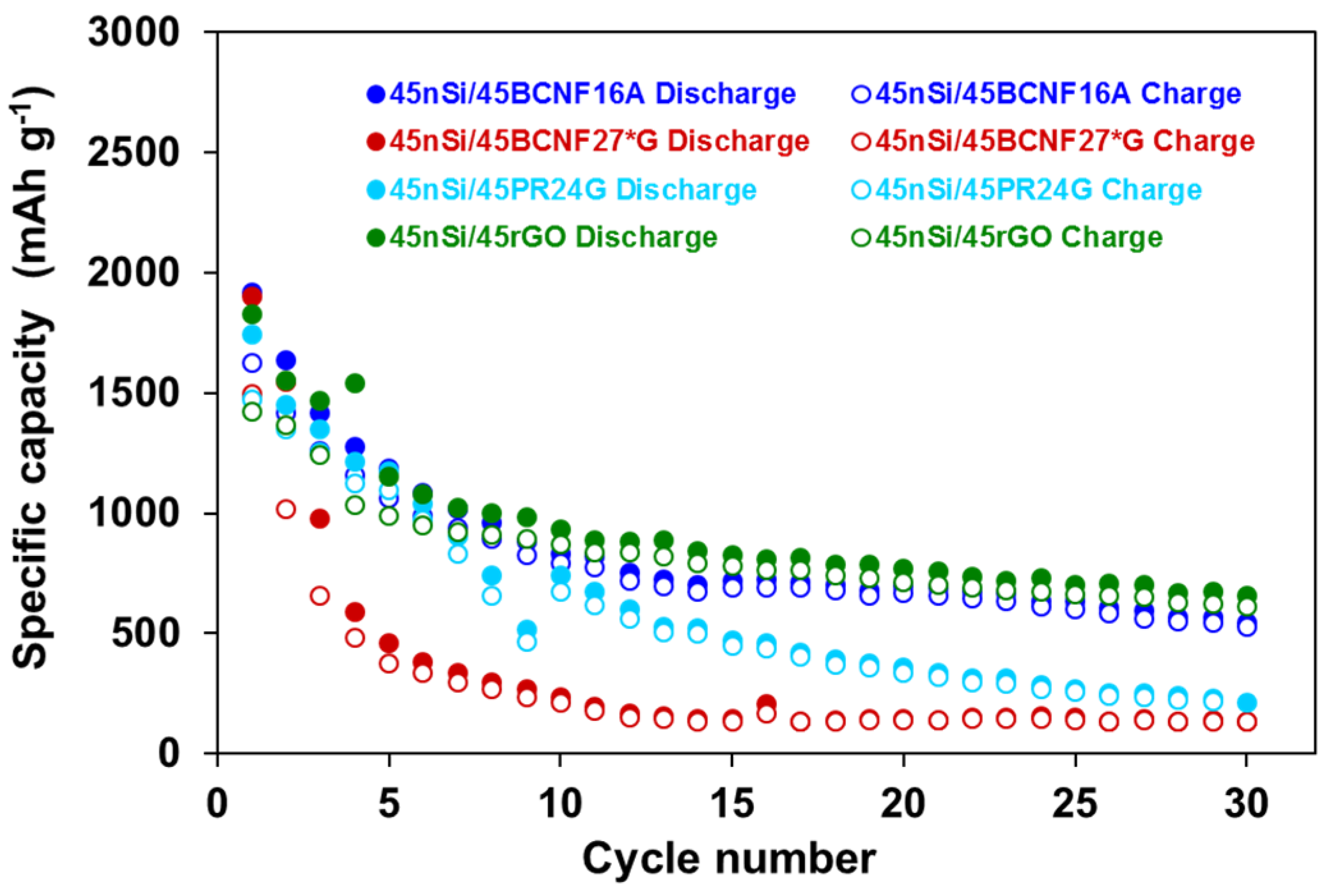
3.1. Influence of nSi Proportion and BCNFs Carbon Matrices on the Electrochemical Performance of nSi/BCNFs Anodes

The main electrochemical parameters, specific discharge capacity (Cdisc) in the 1st, 2nd, 10th, 20th and 30th cycles, irreversible capacity in the 1st discharge–charge cycle (Cirr) and capacity retention (R) from the galvanostatic cycling of several Si-based anodes with different proportions of nSi and BCNFs carbon matrices vs. Li/Li+ in 1M LiPF6 in EC:DEC (1:1, w:w) with 1–5 wt.% of VC, at an electric current density of 100 mA g−1, are summarized in Table 1 and the plots of the specific capacity versus cycle number for some of them appear in Figure 1. To simplify the discussion, they were designated as xnSi/yBCNFs. For comparison, an electrode containing only nSi as active material was also tested. From a general perspective of this data, it can be confirmed that the combination of nSi with BCNFs materials may improve substantially the nSi electrode performance as regards both capacity provided and stability. For example, a discharge capacity of 564 mAh g−1 (being always referred to the mass of the active composite material) at the end of cycling (30 discharge–charge cycles) was determined for 45nSi/45BCNF16A electrode in contrast to a value of only 118 mAh g−1 for nSi electrode; moreover, the discharge capacity retention along cycling of the former is much higher (33% against 8%). However, the scope of this improvement depends largely on nSi:BCNFs’ weight ratio. Regardless of carbon matrix, the presence of small relative nSi amounts (≤30 wt.% in the active composite, nSi:BCNFs weight percentage ratios of 30:60 or 10:80) is not enough to reach acceptable capacities (at least in the order of those determined for graphite electrodes in LIBs). On the contrary, larger nSi proportions (≥60 wt.% in the active composite, nSi:BCNFs 80:10 or 60:30) allow the insertion of a significant number of Li+ ions in the first cycles, as shown by the values of the discharge capacities (i.e., 3167 and 2213 mAh g−1 for 80nSi/10BCNF16A and 60nSi/30BCNF16A electrodes, respectively, in the 2nd cycle).
Nevertheless, the discharge capacity of these electrodes in which the carbon matrix is the minority part of the active composite (≤30 wt.%) fades progressively in the following cycles, thus leading to very low retention capacity at the end of cycling. As an example, between cycles 2 and 20, the discharge capacity provided by the abovementioned electrodes decreased by around 70%. This negative effect is more evident for 80nSi/10BCNF27*A and 60nSi/30BCNF27*A electrodes, which underwent capacity losses of 82% and 76%, respectively, in the same cycling period. Furthermore, as seen in Table 1, no capacity was detected for 80nSi/10BCNF27*G and 60nSi/30BCNF27*G electrodes after 10 discharge–charge cycles.
Therefore, it is evident that, under these conditions, the BCNFs carbon matrices, particularly BCNF27*G, are not accommodating the volume changes associated with the lithiation/delithiation process of the electrodes. An increase of the relative proportion of the carbon matrix in the active composite from 10 to 30 wt.%, up to 45 wt.% (nSi:BCNFs weight percentages ratio of 45:45), in particular for BCNF16A, improves the electrode performance as a whole (Table 1 and Figure 1). In this context, although the 2nd cycle discharge capacity of 45nSi/45BCNF16A electrode is much lower than those of 80nSi/10BCNF16A and 60nSi/30BCNF16A because of the lesser relative amount of nSi, its stability along cycling is better as shown by the higher capacity retention (R) at the end of 30 discharge–charge cycles (33% against 18–24%). Moreover, 45nSi/45BCNF16A shows a plateau between the 12th and 25th cycle, in which this electrode supplies a specific capacity up to ~700 mAh g−1 with a great retention value of 85%. Accordingly, a nSi:BCNF16A percentage weight ratio of 45:45 in the active composite seems to be the most optimal, since it allows a compromise between a suitable specific capacity, which is higher than that of graphitic materials currently commercialized for LIBs, and an acceptable capacity retention along cycling. To a lesser extent, this nSi:C ratio also leads to an enhancement of the electrode parameters by using BCNF27*A carbon matrix. As an example, at the end of cycling, a discharge capacity of 534 mAh g−1 was measured for 45nSi/45BCNF27*A in contrast to a value of 126 mAh g−1 for 10nSi/80BCNF27*A (Table 1). However, except during the 2nd cycle, no improvement is observed for those electrodes prepared with the graphitized BCNF27*G carbon matrix. By comparing these electrochemical results and the textural properties of the BCNFs carbon matrices in Table 2, it is obvious that the decrease of the porosity and the surface area, which are associated with the graphitization treatment (BCNF27*A against BCNF27*G), has a negative impact on the capability of these nanomaterials to accommodate the volume changes during the lithiation/delithiation process. Nevertheless, other factors different than BCNFs textural properties should be responsible of their performance as carbon matrices, since BCNF16A having somewhat lower surface area and porosity than BCNF27*A leads to better electrochemical results (Table 1). From TEM observations [32], it was concluded that the BCNFs produced at 600 °C (BCNF16A) have fishbone (parallel graphene layers tilted with respect to the fiber axis) microstructure, whereas mixtures of fishbone and ribbon (parallel graphene layers which are parallel with respect to the fiber axis) microstructures were detected in those obtained at 700 °C (BCNF27*A). Considering that the number of active edge sites in a fishbone microstructure is much higher than in a ribbon type, BCNFs such as BCNF16A might better interact with nSi particles in the composite, somehow favoring their role as carbon matrix.
For comparative purposes, the galvanostatic plots (specific capacity against cycle number) of 45nSi/45BCNF16A and 45nSi/45BCNF27*G electrodes are presented in Figure 2 together with those in which the commercial nanomaterials: graphitized nanofibers PR24G (45nSi/45PR24G electrode) and reduced graphene oxide rGO (45nSi/45rGO electrode) are the carbon matrices in the active composites. Unlike BCNF27*G [32], the use of PR24G carbon matrix, which is likewise a graphitic nanomaterial [38], initially (1st to 10th cycle) leads to a specific capacity comparable to that determined for 45nSi/45BCNF16A electrode. Nevertheless, in the subsequent cycles, a gradual decrease of the specific capacity provided by 45nSi/45PR24G to a final value of 200 mAh g−1, which is in the order of that measured for 45nSi/45BCNF27*G electrode, is observed. Therefore, it appears that PR24G material accommodates the volume changes associated with lithium insertion/deinsertion to a much greater extent than BCNF27*G. Keeping in mind that PR24G shows a lower surface area (29 m2 g−1 versus 73 m2 g−1 for BCNF27*G in Table 2), the ability of these graphitic nanofilaments to better counteract the negative effect of the volume changes could be only attributed to their stacked-cup microstructure [38], in which the circular section formed by nested (stacked) cones surrounding an inner hollow core provides an extra space for accommodating these changes. Overall, the performance of the Si-based electrode that was prepared with the reduced graphene oxide as the carbon matrix (45nSi/45rGO) is comparable to that of 45nSi/45BCNF16A.
Based on these results, it can be concluded that either no-graphitized carbon nanofibers, particularly those with fishbone microstructure, or low surface area such as BCNF16A, and/or carbon materials supporting a laminar structure and large surface area, such as rGO (SBET ~460 m2 g−1), are suitable carbon matrices for Si-based anodes, because they are able to accommodate the volume changes associated with lithium insertion/deinsertion, thus preventing electrode degradation.

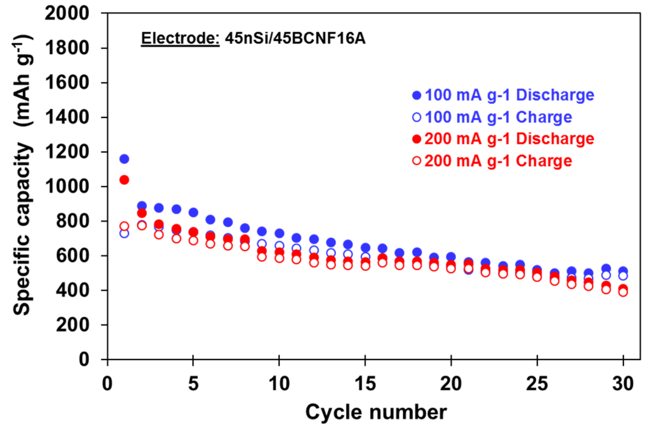
3.2. Influence of Cycling Conditions on the Electrochemical Performance of 45nSi/45BCNF16A Electrode

As seen in the previous section, the use of nSi/BCNFs composites improves significantly the electrode performance compared to one of pure nSi, particularly in the case of 45nSi/45BCNF16A. Even so, the capacity retention along cycling, specifically during the first ten discharge–charge cycles, is still far from excellent and, therefore, it should be increased. On this matter, the influence of cycling conditions, specifically the potential window on the 45nSi/45BCNF16A electrode performance, is herein investigated. First of all, in order to gain further insight into the interaction of the Li+ ions with the active composite during the galvanostatic process, the differential charge/discharge capacity against potential vs. Li/Li+ (<1 V) plot for the 1st, 2nd and 3rd cycles of the 45nSi/45BCNF16A electrode in Figure 3 is discussed. During the first discharge, the potential drops rapidly until ~0.1 V. At this voltage, a broad band associated with the initial lithiation of the crystalline silicon (c-Si) to form an amorphous undefined a-LixSi alloy is observed. In the subsequent charge, a well-defined peak at ~0.44 V, which has been ascribed to the delithiation of the a-Li15Si4 alloy to produce amorphous silicon (a-Si), appears. The lithiation of a-Si during the second discharge results in two bands (~0.24 V and ~0.08 V) and a smaller one at <0.04 V, which corresponds to the formation of the abovementioned a-Li15Si4 phase. As expected, in the following charge cycle, the peak at 0.44 V from the delithiation of this phase is also detected. This is in line with the observations of Obrovac et al. [37] and Li et al. [39] for the lithiation/delithiation mechanism of silicon electrodes. Furthermore, these authors have reported that the Li15Si4 phase is formed when the lower cutoff voltage is <50 mV (3 mV in this work).
According to Obrovac et al. [37], the formation of a stable microstructure composed of a central crystalline Si that remains intact and a crust of amorphous Si in charge of the accommodation of Li+ ions could allow for greater control of the volume changes, thus preventing electrode damage. To this aim, it is necessary (i) to limit the access of Li+ ions during the first cycle, so that the c-Si lithiation is not complete, but it is sufficient to obtain a significant capacity value; and (ii) to avoid the formation of Li15Si4 phase during the subsequent cycles, which would imply the complete electrode lithiation. However, the coincidence of both phenomena in the same potential range makes the simultaneous fulfillment of both requirements difficult. Therefore, it is necessary to reach a compromise through the determination of the most suitable potential range. To this end, 45nSi/45BCNF16A electrode was subjected to galvanostatic cycling at a constant current density of 100 mA g−1 for 50 cycles between an upper cutoff voltage (UCOV) of 0.9 V and a lower cutoff voltage (LCOV) ranging from 3 to 120 mV. The galvanostatic plots (specific capacity against cycle number) and the corresponding differential charge–discharge capacity against potential vs. Li/Li+ plots for the 1st, 2nd and 3rd cycles are presented in Figure 4 and Figure 5, respectively.
Based on the differential capacity profiles of the first cycle (Figure 5), at a LCOV of 120 mV, the lithiation of the electrode has basically not yet started, and this limits its performance along the cycling (Figure 4). As expected, a decrease of the LCOV, from 120 to 3 mV, leads to an improvement in the capacity values during the first cycles, but the capacity retention decreases at the same time, due to the progressive electrode damage. This fact is in accordance with the aforementioned study of Obrovac et al. for Si anodes [37]. Thus, a specific capacity up to ~520 mAh g−1 at 30th cycle with cycling efficiency >95% and excellent capacity retention (R ~ 94%) is determined for 45nSi/45BCNF16A electrode at a LCOV of 100 mV. Although these values decrease after 50 discharge–charge cycles, they can be considered still acceptable, since, for example, the capacity supplied is 425 mAh g−1, which supposes an increase of ~90% with respect to the capacity of a graphite anode at the same current density (~224 mAh g−1 at 100 mA g−1) [40]. A subsequent LCOV reduction to 80 mV causes an increase of the specific capacity along the first cycles, but basically does not affect it after the 15th cycle. From this point, both curves are almost overlapping with a value of R ~ 74% in the 20th–50th cycles (Figure 4). However, for LCOV in the 60–20 mV range, a continuous specific capacity loss along cycling occurs (<200 mAh g−1 after 50 cycles). The formation of the lithiated Li15Si4 phase, which is proved by the presence of the 0.04 V peak in the differential capacity against potential plots (Figure 5), accounts for this negative effect, since it involves the Si crystallization and, therefore, a microstructural change that contributes to electrode damage. This phenomenon is particularly appreciated in the differential capacity plots at LCOV of 40, 20 and 3 mV. Furthermore, for LCOV ≤ 20 mV, the peak corresponding to the delithiation of Li15Si4 phase (0.44 V) is also observed. However, this peak is not detectable at ≥40 mV, probably because the amount of this phase is still very small.
In summary, at LCOV in the 80–100 mV range, it is possible to control the continuous microstructural changes of the silicon, thus restricting the volume changes experienced by the electrode during the lithiation/delithiation process, which leads to values of capacity retention and efficiency comparable to commercial materials, such as graphite, and a specific capacity 2.5 times larger than these materials under similar conditions [40].
In order to corroborate these observations, the galvanostatic cycling of the 45nSi/45BCNF16A electrode was also performed, applying a LCOV of 80 mV, at a higher electric current density of 200 mA g−1. The specific capacity against cycle number plots of this electrode, at both 200 and 100 mA g−1, are shown in Figure 6. As seen, the corresponding profiles are almost overlapping, i.e., both capacity provided and capacity retention are hardly invariable after 30 cycles when the applied current is double, which means a five times greater specific capacity than that supplied by a graphite electrode in similar conditions [40].

4. Conclusions

Nano-silicon/biogas-derived carbon nanofibers composites (nSi/BCNFs) that were prepared by a simple, fast and easily industrial-scaling process were successfully applied as anode materials in lithium-ion batteries, substantially improving the nano-silicon electrode performance, in regard to both capacity and stability. Specific capacities up to 520 mAh g−1 with coulombic efficiency >95% and 94% of capacity retention along cycling were achieved for nSi/BCNFs anodes at an electric current density of 100/200 mA g−1 and a low cutoff voltage of 80 mV.
Among the BCNFs studied, the no-graphitized ones, which were directly obtained from the catalytic decomposition of biogas, with fishbone microstructure, therefore having a great number of active sites to interact with the nSi particles in the composite, were found to be the most suitable carbon matrices, because they are able to better buffer the volume changes associated with the silicon lithiation/delithiation process, thus preventing electrode degradation. Specifically, an nSi:BCNFs 1:1 weight ratio in the anode active composite is the most optimal, since it allows a compromise between a suitable specific capacity, which is greater than that of graphitic materials currently used in LIBs, and an acceptable capacity retention along cycling.
The limitation of the potential cycling range of nSi/BCNFs anodes may control the continuous microstructural changes of the silicon, thus restricting the volume changes experienced by these anodes, which finally enhances their output, particularly the stability. Low cutoff voltage in the 80–100 mV range was found to be the best for the galvanostatic cycling of nSi/BCNFs anodes, because it avoids the formation of the highest lithiated phase (L15Si4) and, therefore, the complete silicon lithiation, which leads to electrode damage.

Supplementary Materials

The following are available online at https://www.mdpi.com/2311-5629/6/2/25/s1. Figure S1: Specific discharge capacity in the 1st, 10th, 20th and 30th cycles from the galvanostatic cycling of different micro-silicon (xmSi/yB)-based and nano-silicon (xnSi/yB)-based electrodes, at an electric current density of 37.2 mA g−1, in the 2.1 V–3 mV potential range. B is the binder, namely sodium carboxymethyl cellulose (NaCMC) and Xanthan gum (XG), and x and y are the weight percentages of silicon and binder, respectively, in the electrode. Figure S2: Specific discharge capacity against cycle number plots from the galvanostatic cycling of 70nSi/10E/20NaCMC electrodes (E: CB, SG-KS6 or BCNF27*G) and 80nSi/20NaCMC electrode at an electric current density of 37.2 mA g−1, in the 2.1 V–3 mV potential range. Figure S3: Specific capacity against cycle number plots from the galvanostatic cycling of DP, MM and SA electrodes, at an electric current density of 100 mA g−1, in the 2.1 V–3 mV potential range. Figure S4: SEM images of DP electrode (a) 250x and (c) 60,000x; and of SA electrode (b) 250x, (d) and (e) 60,000x. Figure S5: SEM/EDX images of (a) DP electrode and (b) SA electrode at 250x. Table S1: Loads (active material + binder) of the different working electrodes used in the galvanostatic cycling vs. Li/Li+ experiments in the potential ranges of 2.1 V–3 mV (data in Table 1 and Figure 1, Figure 2 and Figure 3) and 0.9 V–X mV (X = lower cutoff voltage, LCOV, data in Figure 4, Figure 5 and Figure 6), at 100 mA g−1. Table S2: Electric conductivity (σ) and BET surface area (SBET) of the conductive additives (E).

Author Contributions

Conceptualization, I.C., N.C., A.B.G. and A.R.; methodology, N.C.; investigation, I.C., N.C., A.B.G. and A.R.; writing-original draft preparation, N.C.; writing-review and editing, N.C., I.C. and A.B.G.; supervision, A.B.G.; project administration, A.B.G. and I.C.; funding acquisition, A.B.G. and I.C. All authors have read and agreed to the published version of the manuscript.

Funding

This research was funded by Spanish Ministries of Economy and Competitiveness MINECO (Project ENE2014-52189-C2-2-R) and Science, Innovation and Universities (Project RTI2018-094286-A-100), and Asturian Regional Government (GRUPIN 2018, Ref. IDI/2018/000234).

Acknowledgments

Financial support from the Spanish Ministries of Economy and Competitiveness MINECO and Science, Innovation and Universities and Asturias Regional Government is gratefully acknowledged. I. Cameán and N. Cuesta respectively acknowledge the funding from Fundación General CSIC (Programa ComFuturo) and from MINECO for Ph.D. grant (BES-2012-052711).

Conflicts of Interest

The authors declare no conflict of interest.

References

  1. Nitta, N.; Wu, F.; Lee, J.T.; Yushin, G. Li-ion battery materials: Present and future. Mater. Today 2015, 18, 252–264. [Google Scholar] [CrossRef]
  2. Mishra, A.; Mehta, A.; Basu, S.; Malode, S.J.; Shetti, N.P.; Shukla, S.S.; Nadagouda, M.N.; Aminabhavi, T.M. Electrode materials for lithium-ion batteries. Mater. Sci. Energy Technol. 2018, 1, 182–187. [Google Scholar] [CrossRef]
  3. Ozanam, F.; Rosso, M. Silicon as anode material for Li-ion batteries. Mater. Sci. Eng. B 2016, 213, 2–11. [Google Scholar] [CrossRef]
  4. Li, P.; Zhao, G.; Zheng, X.; Xu, X.; Yao, C.; Sun, W.; Dou, S.X. Recent progress on silicon-based anode materials for practical lithium-ion battery applications. Energy Storage Mater. 2018, 15, 422–446. [Google Scholar] [CrossRef]
  5. Casimir, A.; Zhang, H.; Ogoke, O.; Amine, J.C.; Lu, J.; Wu, G. Silicon-based anodes for lithium-ion batteries: Effectiveness of materials synthesis and electrode preparation. Nano Energy 2016, 27, 359–376. [Google Scholar] [CrossRef] [Green Version]
  6. Obrovac, M.N. Si-alloy negative electrodes for Li-ion batteries. Curr. Opin. Electrochem. 2018, 9, 8–17. [Google Scholar] [CrossRef]
  7. Obrovac, M.N.; Christensen, L. Structural changes in silicon anodes during lithium insertion/extraction. Electrochem. Solid State Lett. 2004, 7, A93–A96. [Google Scholar] [CrossRef]
  8. Ryu, J.H.; Kim, J.W.; Sung, Y.-E.; Oh, S.M. Failure modes of silicon powder negative electrode in lithium secondary batteries. Electrochem. Solid State Lett. 2004, 7, A306–A309. [Google Scholar] [CrossRef]
  9. Song, M.-K.; Park, S.; Alamgir, F.M.; Cho, J.; Liu, M. Nanostructured electrodes for lithium-ion and lithium-air batteries: The latest developments, challenges, and perspectives. Mater. Sci. Eng. R Rep. 2011, 72, 203–252. [Google Scholar] [CrossRef]
  10. Xu, W.; Vegunta, S.S.S.; Flake, J.C. Surface-modified silicon nanowire anodes for lithium-ion batteries. J. Power Sources 2011, 196, 8583–8589. [Google Scholar] [CrossRef]
  11. Shen, X.; Tian, Z.; Fan, R.; Shao, L.; Zhang, D.; Cao, G.; Kou, L.; Bai, Y. Research progress on silicon/carbon composite anode materials for lithium-ion battery. J. Energy Chem. 2018, 27, 1067–1090. [Google Scholar] [CrossRef] [Green Version]
  12. Kasavajjula, U.; Wang, C.; Appleby, A.J. Nano- and bulk-silicon-based insertion anodes for lithium-ion secondary cells. J. Power Sources 2007, 163, 1003–1039. [Google Scholar] [CrossRef]
  13. Liang, B.; Liu, Y.; Xu, Y. Silicon-based materials as high capacity anodes for next generation lithium ion batteries. J. Power Sources 2014, 267, 469–490. [Google Scholar] [CrossRef]
  14. Shao, D.; Tang, D.; Yang, J.; Li, Y.; Zhang, L. Nano-structured composite of Si/(S-doped-carbon nanowire network) as anode material for lithium-ion batteries. J. Power Sources 2015, 297, 344–350. [Google Scholar] [CrossRef]
  15. Morita, T.; Takami, N. Nano Si cluster-SiOx-C composite material as high-capacity anode material for rechargeable lithium batteries. J. Electrochem. Soc. 2006, 153, A425–A430. [Google Scholar] [CrossRef]
  16. Szczech, J.R.; Jin, S. Nanostructured silicon for high capacity lithium battery anodes. Energy Environ. Sci. 2011, 4, 56–72. [Google Scholar] [CrossRef]
  17. Magasinski, A.; Zdyrko, B.; Kovalenko, I.; Hertzberg, B.; Burtovyy, R.; Huebner, C.F.; Fuller, T.F.; Luzinov, I.; Yushin, G. Toward efficient binders for Li-ion battery Si-based anodes: Polyacrylic acid. ACS Appl. Mater. Interfaces 2010, 2, 3004–3010. [Google Scholar] [CrossRef]
  18. Komaba, S.; Yabuuchi, N.; Ozeki, T.; Han, Z.-J.; Shimomura, K.; Yui, H.; Katayama, Y.; Miura, T. Comparative study of sodium polyacrylate and poly(vinylidene fluoride) as binders for high capacity Si–graphite composite negative electrodes in Li-ion batteries. J. Phys. Chem. C 2012, 116, 1380–1389. [Google Scholar] [CrossRef]
  19. Liu, W.-R.; Yang, M.-H.; Wu, H.-C.; Chiao, S.M.; Wu, N.-L. Enhanced cycle life of Si anode for Li-ion batteries by using modified elastomeric binder. Electrochem. Solid State Lett. 2005, 8, A100–A103. [Google Scholar] [CrossRef]
  20. Buqa, H.; Holzapfel, M.; Krumeich, F.; Veit, C.; Novák, P. Study of styrene butadiene rubber and sodium methyl cellulose as binder for negative electrodes in lithium-ion batteries. J. Power Sources 2006, 161, 617–622. [Google Scholar] [CrossRef]
  21. Mazouzi, D.; Lestriez, B.; Roué, L.; Guyomard, D. Silicon composite electrode with high capacity and long cycle life. Electrochem. Solid State Lett. 2009, 12, A215–A218. [Google Scholar] [CrossRef]
  22. Li, J.; Lewis, R.; Dahn, J. Sodium carboxymethyl cellulose a potential binder for Si negative electrodes for Li-ion batteries. Electrochem. Solid State Lett. 2007, 10, A17–A20. [Google Scholar] [CrossRef]
  23. Beattie, S.D.; Larcher, D.; Morcrette, M.; Simon, B.; Tarascon, J.-M. Si Electrodes for Li-Ion Batteries—A New Way to Look at an Old Problem. J. Electrochem. Soc. 2008, 155, A158–A163. [Google Scholar] [CrossRef]
  24. Hochgatterer, N.; Schweiger, M.; Koller, S.; Raimann, P.; Wöhrle, T.; Wurm, C.; Winter, M. Silicon/graphite composite electrodes for high-capacity anodes: Influence of binder chemistry on cycling stability. Electrochem. Solid State Lett. 2008, 11, A76–A80. [Google Scholar] [CrossRef]
  25. Bridel, J.S.; Azaïs, T.; Morcrette, M.; Tarascon, J.M.; Larcher, D. Key parameters governing the reversibility of Si/carbon/CMC electrodes for Li-ion batteries. Chem. Mater. 2010, 22, 1229–1241. [Google Scholar] [CrossRef]
  26. Guo, J.; Wang, C. A polymer scaffold binder structure for high capacity silicon anode of lithium-ion battery. Chem. Commun. 2010, 46, 1428–1430. [Google Scholar] [CrossRef]
  27. Lux, S.F.; Schmuck, M.; Jeong, S.; Passerini, S.; Winter, M.A.; Balducci, A. Li-ion anodes in air-stable and hydrophobic ionic liquid-based electrolyte for safer and greener batteries. Int. J. Energy Res. 2010, 34, 97–106. [Google Scholar] [CrossRef]
  28. Kovalenko, I.; Zdyrko, B.; Magasinski, A.; Hertzberg, B.; Milicev, Z.; Burtovyy, R.; Luzinov, I.; Yushin, G. A major constituent of brown algae for use in high-capacity Li-ion batteries. Science 2011, 334, 75–79. [Google Scholar] [CrossRef]
  29. Yue, L.; Zhang, L.; Zhong, H. Carboxymethyl chitosan: A new water soluble binder for Si anode of Li-ion batteries. J. Power Sources 2014, 247, 327–331. [Google Scholar] [CrossRef]
  30. Kuruba, R.; Datta, M.K.; Damodaran, K.; Jampani, P.H.; Gattu, B.; Patel, P.P.; Shanthi, P.M.; Damle, S.; Kumta, P.N. Guar gum: Structural and electrochemical characterization of natural polymer based binder for silicon–carbon composite rechargeable Li-ion battery anodes. J. Power Sources 2015, 298, 331–340. [Google Scholar] [CrossRef] [Green Version]
  31. Ling, M.; Xu, Y.; Zhao, H.; Gu, X.; Qiu, J.; Li, S.; Wu, M.; Song, X.; Yan, C.; Liu, G.; et al. Dual-functional gum arabic binder for silicon anodes in lithium ion batteries. Nano Energy 2015, 12, 178–185. [Google Scholar] [CrossRef] [Green Version]
  32. Cuesta, N.; Cameán, I.; Ramos, A.; de Llobet, S.; García, A.B. Graphitic nanomaterials from biogas-derived carbon nanofibers. Fuel Process. Technol. 2016, 152, 1–6. [Google Scholar] [CrossRef] [Green Version]
  33. Leveau, L.; Laïk, B.; Pereira-Ramos, J.-P.; Gohier, A.; Tran-Van, P.; Cojocaru, C.-S. Cycling strategies for optimizing silicon nanowires performance as negative electrode for lithium battery. Electrochim. Acta 2015, 157, 218–224. [Google Scholar] [CrossRef]
  34. Cui, L.-F.; Ruffo, R.; Chan, C.K.; Peng, H.; Cui, Y. Crystalline-amorphous core−shell silicon nanowires for high capacity and high current battery electrodes. Nano Lett. 2009, 9, 491–495. [Google Scholar] [CrossRef] [PubMed]
  35. Chan, C.K.; Peng, H.; Liu, G.; McIlwrath, K.; Zhang, X.F.; Huggins, R.A.; Cui, Y. High-performance lithium battery anodes using silicon nanowires. Nature Nanotechol. 2008, 3, 31–35. [Google Scholar] [CrossRef] [PubMed]
  36. Liu, X.H.; Wang, J.W.; Huang, S.; Fan, F.; Huang, X.; Liu, Y.; Krylyuk, S.; Yoo, J.; Dayeh, S.A.; Davydov, A.V. In situ atomic-scale imaging of electrochemical lithiation in silicon. Nature Nanotechol. 2012, 7, 749–756. [Google Scholar] [CrossRef]
  37. Obrovac, M.N.; Krause, L.J. Reversible cycling of crystalline silicon powder. J. Electrochem. Soc. 2007, 154, A103–A108. [Google Scholar] [CrossRef]
  38. Ramos, A.; Cameán, I.; Cuesta, N.; García, A.B. Graphitized stacked-cup carbon nanofibers as anode materials for lithium-ion batteries. Electrochim. Acta 2014, 146, 769–775. [Google Scholar] [CrossRef]
  39. Li, J.; Dahn, J.R. An in situ X-Ray diffraction study of the reaction of Li with crystalline Si. J. Electrochem. Soc. 2007, 154, A156–A161. [Google Scholar] [CrossRef]
  40. Cuesta, N.; Cameán, I.; Ramos, A.; García, A.B. Graphitized biogas-derived carbon nanofibers as anodes for lithium-ion batteries. Electrochim. Acta 2016, 222, 264–270. [Google Scholar] [CrossRef] [Green Version]
Figure 1. Specific discharge/charge capacity against cycle number plots from the galvanostatic cycling vs. Li/Li+ at 100 mA g−1 of nSi, of 10nSi/80BCNF16A, 30nSi/60BCNF16A, 45nSi/45BCNF16A, 60nSi/30BCNF16A and 80nSi/10BCNF16A electrodes, in the 2.1 V–3 mV potential range.
Carbon 06 00025 g001
Figure 2. Specific discharge/charge capacity against cycle number plots from the galvanostatic cycling vs. Li/Li+ at 100 mA g−1 of nSi/C electrodes with equal nSi:C weight ratio and different carbon matrix, namely 45nSi/45BCNF16A, 45nSi/45BCNF27*G, 45nSi/45PR24G and 45nSi/45rGO, in the 2.1 V–3 mV potential range.
Carbon 06 00025 g002
Figure 3. Differential charge/discharge capacity against potential vs. Li/Li+ plots from the galvanostatic cycling at 100 mA g−1 of 45nSi/45BCNF16A electrode for cycles 1st, 2nd and 3rd, in the 2.1 V–3 mV potential range.
Carbon 06 00025 g003
Figure 4. Specific discharge/charge capacity against cycle number plots from the galvanostatic cycling vs. Li/Li+ at 100 mA g−1 of 45nSi/45BCNF16A electrode, in the 0.9 V to X mV potential range. X = lower cutoff voltage (LCOV).
Carbon 06 00025 g004
Figure 5. Differential charge/discharge capacity against potential vs. Li/Li+ plots from the galvanostatic cycling at 100 mA g−1 of 45nSi/45BCNF16A electrode for cycles 1st, 2nd and 3rd, in the 0.9 V–X mV potential range. X = lower cutoff voltage (LCOV).
Carbon 06 00025 g005
Figure 6. Specific discharge/charge capacity against cycle number plots from the galvanostatic cycling vs. Li/Li+ at 100 and 200 mA g−1 of 45nSi/45BCNF16A electrode, in the 0.9 V–80 mV potential range.
Carbon 06 00025 g006
Table 1. Specific discharge capacity (Cdisc) in the 1st, 2nd, 10th, 20th and 30th cycles, irreversible capacity in the 1st cycle (Cirr) and capacity retention (R) parameters from the galvanostatic cycling vs. Li/Li+ of Si-based electrodes with different proportions of nSi and BCNFs, at an electric current density of 100 mA g−1.
ElectrodeCdisc 1st Cycle (mAh g−1)Cdisc 2nd Cycle (mAh g−1)Cdisc 10th Cycle (mAh g−1)Cdisc 20th Cycle (mAh g−1)Cdisc 30th Cycle (mAh g−1)Cirr a 1st Cycle (%)R b 2nd–30th Cycles (%)
80nSi/10BCNF27*G18711343607--------
60nSi/30BCNF27*G18031473512--------
45nSi/45BCNF27*G19001549237146136219
30nSi/60BCNF27*G118786721810862307
10nSi/80BCNF27*G7184682871551873940
80nSi/10BCNF27*A264318904643462293012
60nSi/30BCNF27*A252519577534643143716
45nSi/45BCNF27*A3191285215589045342819
30nSi/60BCNF27*A118110437484071831415
10nSi/80BCNF27*A7384653431831264927
80nSi/10BCNF16A3964316712729467482824
60nSi/30BCNF16A243922138745693911818
45nSi/45BCNF16A191616408346965451533
30nSi/60BCNF16A1516132545817499277
10nSi/80BCNF16A8005744052422353841
nSi35541747302155118--8
a Irreversible capacity (%) = [Cdisc (1st cycle) − Ccharge (1st cycle)] [Cdisc (1st cycle)]−1 × 100. b Capacity retention (%) = [Cdisc (30th cycle)] [Cdisc (2nd cycle)]−1 × 100.
Table 2. Textural parameters of carbon matrices: BET surface area (SBET), Total N2 pore volume (Vt), mesopore volume (VMESO) and micropore volume (VMICRO).
Carbon MatrixSBET (m2 g−1)Vt (cm3 g−1)VMESO (cm3 g−1)VMICRO (cm3 g−1)
BCNF16A960.2400.1710.011
BCNF27*A1130.3920.3330.010
BCNF27*G730.2790.2790.010
rGO460------
PR24G29------

