Article

Surface-Integrated Hydrogen Sensing Using ZnFe2O4–CNT Composite Coatings on Cement-Based Materials with Data-Driven Concentration Prediction


by
Mohammadmahdi Abedi
1,2,*,
Zivar Azmoodeh
3 and
Eloi Figueiredo
1,4
1
Faculty of Engineering, Lusófona University, Campo Grande, 376, 1749-024 Lisboa, Portugal
2
Institute for Sustainability and Innovation in Structural Engineering (ISISE), Department of Civil Engineering, University of Minho, 4800-058 Guimarães, Portugal
3
Department of Petroleum and Chemical Engineering, College of Engineering, Sultan Qaboos University, Muscat 123, Oman
4
CERIS, Instituto Superior Técnico, University of Lisbon, Av. Rovisco Pais, 1749-024 Lisboa, Portugal
*
Author to whom correspondence should be addressed.
Submission received: 27 April 2026 / Revised: 31 May 2026 / Accepted: 1 June 2026 / Published: 9 June 2026
(This article belongs to the Section Carbon Materials and Carbon Allotropes)

Abstract

Transforming existing structural surfaces into sensing interfaces offers a promising route for scalable hydrogen monitoring in hydrogen-handling facilities, where leakage poses significant safety risks, addressing the limitations of conventional point-based sensors. In this study, a surface-integrated ZnFe2O4–CNT (ZFC) composite coating is developed as a potentially retrofit-compatible sensing solution to enable hydrogen sensing directly on cementitious materials, combining material-level functionality with data-driven concentration prediction. The ZFC composite was synthesized via a hydrothermal method followed by CNT functionalization and composite formation, and was then applied onto cement-based substrates using a thickness-controlled coating approach. Structural and morphological characterization (XRD, FESEM, TEM, BET) confirmed the formation of a hierarchical, porous architecture, while hydrogen sensing performance was evaluated under controlled thermo-hygrometric conditions (24–72 °C, 32–87% RH) at 10,000 ppm H2. The sensor exhibited stable and reversible responses, with optimal performance at 39–52 °C and a minimum response time of 18 s. An XGBoost model enabled accurate prediction of hydrogen concentration, achieving R2 ≈ 0.92 and RMSE ≈ 820 ppm under dynamic exposure. These results demonstrate that coupling redox-active oxide surfaces with conductive CNT networks enables effective surface-based chemiresistive sensing under realistic conditions. The proposed system transforms conventional cementitious materials into smart, surface-integrated hydrogen sensing systems, offering a scalable and retrofit-compatible approach for real-time monitoring in hydrogen-related infrastructure.

1. Introduction

Hydrogen (H2) is extensively used in a wide range of industrial facilities, including petroleum refineries, chemical processing plants, H2 refueling stations, and dedicated storage and transport systems, where it is handled under pressurized and reactive conditions [1,2,3]. In petroleum refining, hydrogen is a key reactant in hydrocracking and hydrotreating processes, typically operating at elevated pressures and temperatures, while in the chemical industry it serves as a fundamental feedstock for large-scale production of ammonia and methanol [2]. In addition, hydrogen is increasingly deployed in energy systems such as fuel cells and stationary storage units, further expanding its presence across engineered facilities [3]. Despite its advantages as a clean energy carrier, hydrogen poses significant safety challenges due to its physicochemical properties, including a wide flammability range in air (≈4–75 vol%) and extremely low ignition energy (~0.02 mJ), which substantially increase the likelihood of accidental ignition even under minor leakage conditions [4,5]. Given that H2 leakage can occur at valves, joints, and process interfaces, the early detection of H2 accumulation is therefore critical for ensuring operational safety and preventing catastrophic events in hydrogen-handling facilities [5].
H2 sensing technologies have been extensively explored using a variety of material systems and transduction mechanisms, each offering distinct advantages and limitations. Palladium-based sensors represent one of the most established approaches due to the reversible formation of palladium hydride (PdHx), which induces measurable changes in electrical resistance or optical properties. For example, Hübert et al. [6] provided a comprehensive review of palladium-based H2 sensors, highlighting their fast response and high sensitivity at low concentrations. However, these systems are prone to hysteresis, long-term instability, and poisoning effects, particularly under cyclic exposure and in the presence of impurities. Similarly, Wadell et al. [7] demonstrated nanostructured Pd-based plasmonic H2 sensors with rapid optical response, but the approach requires complex nanofabrication and optical readout systems, limiting scalability and practical deployment.
Semiconducting metal oxide (MOX) sensors constitute another major class of H2 sensors, widely investigated due to their robustness and sensitivity. Shankar et al. [8] reviewed metal oxide gas sensors and showed that materials such as ZnO and SnO2 can provide high sensitivity to H2 through surface redox reactions. However, these sensors typically require elevated operating temperatures (200–400 °C) to activate surface reactions, resulting in increased power consumption and limiting their applicability in temperature-sensitive environments. Efforts to improve performance using noble metal catalysts have been reported; for instance, Yamazoe [9] demonstrated that Pd or Pt loading enhances H2 sensitivity by promoting dissociation and spillover effects. Nevertheless, such modifications increase material cost and do not eliminate the fundamental temperature dependence of MOX-based sensing.
Carbon-based materials, particularly carbon nanotubes (CNTs), have also been investigated due to their high electrical conductivity and large specific surface area. Kong et al. [10] demonstrated H2 sensing using single-walled carbon nanotubes functionalized with palladium, achieving room-temperature detection with rapid response. However, the sensing mechanism relies strongly on Pd decoration, and the performance is often affected by instability in CNT networks, baseline drift, and sensitivity to environmental factors such as humidity. Sayago et al. [11] further reported CNT-based H2 sensors with improved sensitivity, but highlighted challenges related to reproducibility and long-term stability due to variations in nanotube dispersion and contact resistance.
More advanced sensing architectures, including field-effect transistor (FET)-based H2 sensors, have been proposed to enhance sensitivity and enable integration with electronic platforms. Paska et al. [12] reviewed FET-based gas sensors employing nanostructured channels such as CNTs and metal oxides, demonstrating improved signal amplification and low detection limits. However, these devices typically require complex microfabrication processes and precise electronic interfacing, which limit their scalability and applicability over large-area structural surfaces.
Despite the significant progress achieved across these material systems, a common limitation persists: most H2 sensing technologies are implemented as discrete, device-level sensors requiring localized installation and dedicated interfacing. As highlighted by Hübert et al. [6] and Shimizu and Egashira [7], current research has primarily focused on improving sensitivity, selectivity, and response time at the device scale, while comparatively less attention has been given to scalable deployment strategies over large structural surfaces. Consequently, although high-performance hydrogen detection can be achieved under controlled conditions, the practical implementation of these sensors in large-scale hydrogen-handling facilities remains constrained by installation complexity, limited spatial coverage, and integration challenges.
While the limitations of existing H2 sensors are well recognized, these challenges become more critical when considering deployment in real hydrogen-handling facilities. In such environments, hydrogen leakage is not confined to a single point but may occur across distributed interfaces, including valves, joints, pipelines, and processing units. This spatially distributed risk requires sensing strategies capable of providing coverage beyond localized measurements. However, current sensor technologies remain predominantly device-based and are not designed for large-area deployment on structural surfaces.
In this context, surface-applied sensing approaches emerge as a promising alternative, offering the possibility of transforming passive structural components into active sensing interfaces [13,14,15]. Such strategies enable conformal, large-area coverage and can be implemented directly on existing substrates without requiring substantial modification of the infrastructure. Nevertheless, there is still a lack of systematic studies investigating H2 sensing coatings on realistic engineering materials, particularly cementitious substrates, under variable temperature and humidity conditions representative of real operational environments. In addition, the integration of data-driven methods for interpreting sensing signals under such conditions remains largely unexplored [16]. Therefore, a critical gap exists in the development of H2 sensing systems that are not only sensitive and stable at the material level, but also scalable, surface-deployable, and compatible with real infrastructure environments.
To address the above-mentioned challenges, the selection of suitable sensing materials for coating-based H2 detection requires a combination of surface reactivity, semiconducting behavior, and compatibility with scalable surface-deposition strategies [17]. In this context, spinel ferrites (MFe2O4) have attracted considerable attention for gas-sensing applications due to their tunable electronic structures and redox-active surfaces [16]. Several ferrite compositions such as NiFe2O4 and CoFe2O4 have been extensively investigated for VOC sensing, catalytic, and magnetic applications [18]. Among these materials, ZnFe2O4 (ZF) has demonstrated promising behavior specifically for chemiresistive H2 sensing through surface redox reactions involving adsorbed oxygen species and defect-mediated charge transfer [13,19]. Previous studies have reported measurable H2 responses from ZF-based nanostructures [20,21]. In particular, Achary et al. [21] demonstrated H2 detection using a ZF-based composite with fast response and operation near ambient conditions, highlighting the potential of zinc ferrite as an active sensing phase.
In addition, ZF offers relatively lower toxicity and material cost compared with Co-based ferrites while maintaining suitable semiconducting characteristics and compatibility with conductive carbon-based systems [22]. Based on these considerations, ZF was selected in the present study as the ferrite phase for the proposed surface-integrated hydrogen sensing framework.
However, the relatively low intrinsic electrical conductivity of ZF limits its standalone performance in chemiresistive sensing applications [17]. To overcome this limitation, CNTs are incorporated as a conductive phase to form a ZF–CNT composite structure. CNTs provide high electrical conductivity, large specific surface area, and efficient electron transport pathways, enabling rapid transduction of resistance changes induced by surface reactions. Kong et al. [10] demonstrated that CNT-based H2 sensors functionalized with catalytic phases enable room-temperature detection through modulation of electrical resistance, while subsequent studies have confirmed the role of CNT networks in improving signal stability and charge transport [17].
The resulting ZF–MWCNT (ZFC) composite combines the surface reactivity of the metal oxide with the electrical conductivity of the CNT network. This composite architecture can facilitate effective modulation of electrical resistance upon H2 exposure by coupling surface redox reactions with efficient charge transport. In addition, previous studies on ZF/carbon systems have shown that the incorporation of conductive carbon phases enhances electron transfer and overall sensing performance [23]. Furthermore, the powder-based nature of ZFC makes it inherently suitable for surface deposition techniques such as spray coating. This characteristic enables conformal application on engineering substrates and supports the development of surface-applied, large-area sensing layers, aligning with the concept of potentially retrofit-compatible H2 sensing systems [21].
Based on the identified knowledge gaps, this study develops a ZFC coating system for H2 sensing that can be directly applied onto existing cementitious substrates, enabling structural surfaces to function as active sensing interfaces. Unlike conventional H2 sensors that operate as discrete, device-level units, the proposed approach introduces a surface-deployable sensing layer capable of providing spatially distributed sensing capability over large areas [17].
The novelty of this work lies in the development of a ZFC-based coating system combined with its implementation on real structural substrates and the integration of data-driven analysis within a unified framework, including evaluation under variable thermo-hygrometric conditions. This approach enables scalable and conformal sensing while remaining compatible with existing infrastructure without structural modification.
This study contributes to the advancement of H2 sensing by introducing a coating-based sensing paradigm that enables hydrogen-responsive functionality on cementitious structural surfaces through a surface-integrated ZnFe2O4–CNT architecture. While the present work experimentally demonstrates the sensing concept on laboratory-scale coated specimens, the proposed system provides a proof-of-concept pathway toward scalable and potentially retrofit-compatible surface-integrated sensing approaches. Since the sensing response is governed by localized gas–surface redox interactions coupled with CNT-mediated charge transport, the underlying chemiresistive mechanism is not inherently restricted to the specimen dimensions investigated here. Nevertheless, further studies are required to evaluate large-area coating uniformity, spatial sensing distribution, and field-scale implementation under realistic operational conditions. From a broader perspective, this work supports the development of infrastructure-integrated sensing materials for hydrogen-related environments.

2. Materials and Methods

2.1. Raw Materials

Zinc nitrate hexahydrate (Zn(NO3)2·6H2O, ≥98%, Merck, Darmstadt, Germany) and iron(III) nitrate hexahydrate (Fe(NO3)2·9H2O, ≥98%, Merck) were used as zinc and iron precursors for the synthesis of ZF [24,25]. During the synthesis process, urea and ascorbic acid were used to aid in the hydrolysis of the precursor and enhance the formation of the ferrite spherical structure. Commercial multi-walled carbon nanotubes (MWCNTs, Merck, Darmstadt, Germany) were used as the conductive carbon phase in the ZFC composite [26,27]. Prior to composite preparation, the MWCNTs were chemically treated using a solution consisting of H2SO4 (≥98%, Merck)/HNO3 (≥65%, Merck, Darmstadt, Germany) to remove residual impurities and introduce oxygen-containing surface features that improve their dispersion and promote physical contact with the oxide particles [28,29,30]. Ethanol and deionized water were used as dispersion media in the synthesis and preparation of the composite. All reagents were of analytical grade and were used without further purification.

2.2. Synthesis of Spinel ZF Nanostructures

ZF was synthesized via a hydrothermal method. In a typical procedure, zinc nitrate (1.30 g) and iron nitrate (3.24 g) were separately dissolved in 10 mL deionized water and a homogeneous precursor solution was obtained under magnetic stirring. Subsequently, aqueous solutions of ascorbic acid and urea (3.17 g) were added dropwise to the metal salt solution and the resulting mixture was stirred for 30 min to completely homogenize. The final solution was then transferred to a Teflon-lined stainless-steel autoclave and heated at 160 °C for 6 h. After cooling naturally to room temperature, the resulting precipitate was thoroughly washed several times with deionized water and ethanol and dried at 60 °C. The dried powder was finally calcined at 500 °C for 2 h to obtain crystalline ZF.

2.3. Synthesis of the ZFC Composite

To prepare the ZFC composite, the MWCNTs were first annealed at 300 °C for 1 h to remove volatile surface contaminants and improve their dispersion behavior. They were then dispersed in a 3:1 H2SO4/HNO3 mixture and sonicated at 50 °C for 2 h. The resulting suspension was washed repeatedly with deionized water to reach neutral pH and then dried at 60 °C. ZF powder was prepared and the functionalized MWCNTs were subsequently sonicated separately. After achieving uniform dispersions, the two suspensions were combined and sonicated to promote homogeneous mixing and physical contact between the ZF particles and the functionalized MWCNT network. The resulting composite was then collected, washed, and dried. A schematic illustration of the overall synthesis and composite formation process is presented in Figure 1.

2.4. ZFC-Coated Cementitious Disc Preparation

Cementitious specimens were prepared in accordance with EN 196-1 [31] using 450 g of cement, 1350 g of CEN standard sand, and 225 g of water. Mixing was performed with a standard mortar mixer following the prescribed sequence, and the fresh mortar was cast into cylindrical PVC molds (30 mm internal diameter). After 24 h, specimens were demolded and cured at 20 ± 1 °C and ≥90% relative humidity for 28 days. The cured cylinders were then sectioned into discs with a thickness of 5 ± 1 mm, and the exposed surfaces were dried and cleaned prior to coating. An epoxy interlayer was applied using a thickness-controlled casting method. A rigid spacer frame with a 2.0 mm gap was fixed on the substrate, and the epoxy was distributed and levelled using a doctor-blade applicator to form a uniform layer of approximately 2 mm thickness. This interlayer reduced surface roughness, improved adhesion of the ZFC layer, and acted as a low-permeability barrier against moisture and reactive gas ingress into the cement pore structure. Furthermore, the epoxy layer provided a mechanically stable and reproducible interfacial support for the sensing coating, helping to maintain coating integrity and controlled surface exposure conditions during cyclic sensing measurements. While the epoxy contributed to interfacial stabilization, the sensing response itself originated from the ZFC active layer. While the epoxy remained tacky, ZFC powder was deposited using a controlled filling approach. A second spacer frame (2.0 mm) was placed, and a pre-weighed amount of powder was uniformly distributed and levelled to achieve a nominal ZFC thickness of 2 mm. This thickness enabled partial embedment (~1 mm) into the epoxy, enhancing mechanical interlocking and coating integrity under cyclic loading. The selected 2 mm coating thickness was determined based on preliminary fabrication and sensing trials as a practical compromise between coating uniformity, mechanical stability, interfacial adhesion, and sufficient exposed active surface for gas interaction. Excessively thin layers exhibited lower structural integrity, while thicker coatings may limit effective gas diffusion and increase mechanical fragility during cyclic operation.
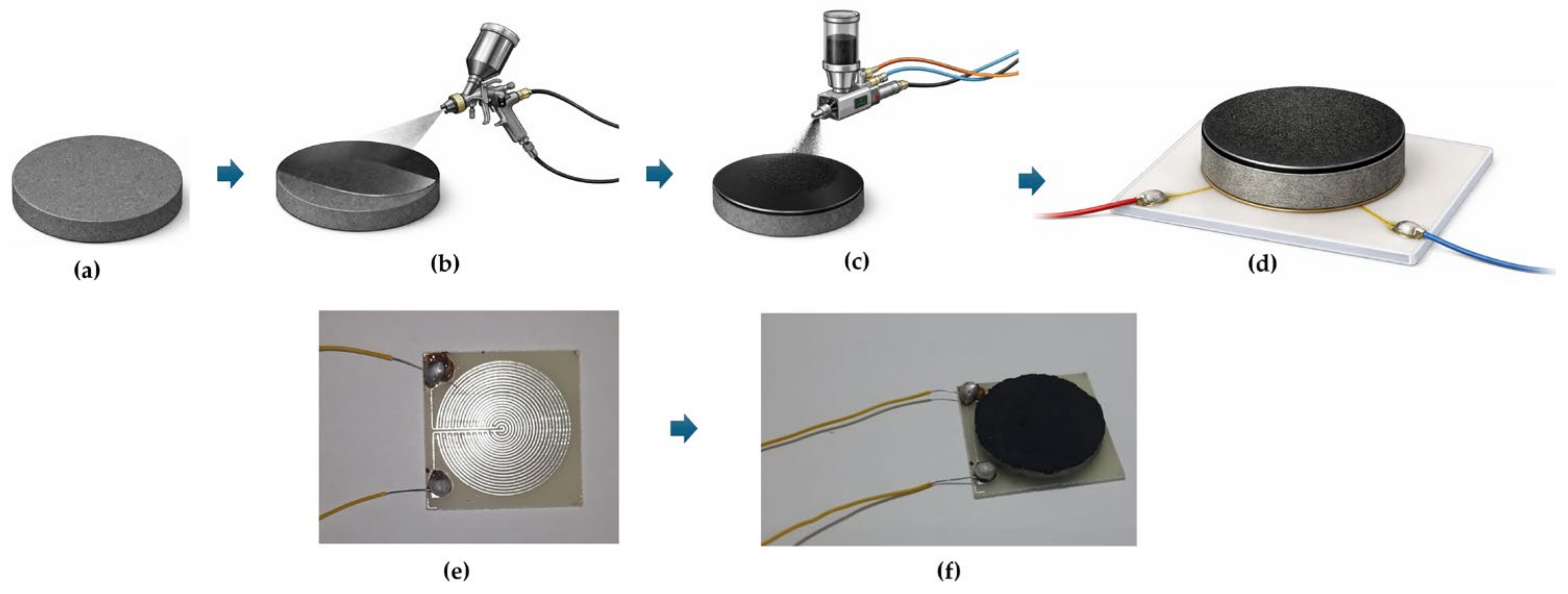
The specimens were then kept under ambient laboratory conditions for 7 days to ensure full epoxy curing. For electrical read-out, the ZFC-coated cementitious disc was mounted onto a planar spiral copper coil using a conductive adhesive to ensure stable electrical contact (Figure 2). The coil was fabricated on a 2 mm thick PET substrate, with its active diameter matched to that of the cementitious disc. The coil terminals were soldered to insulated lead wires, which were routed from opposite corners along the lower edge of the square support. This configuration was designed to fit the base of the micro-chamber, ensure consistent positioning relative to the gas-flow path, and provide a modular setup that can be readily extended to larger coated cement-based elements for field-relevant applications.

2.5. ZFC Characterization Methods

The crystalline structure of the prepared samples was examined by X-ray diffraction (XRD) using a Philips X’Pert (Almelo, The Netherlands) diffractometer equipped with Cu Kα radiation (λ = 1.5406 Å). The diffraction patterns were recorded over a 2θ range of 20–80° with a step size of 0.02°. The morphological features of ZF, MWCNTs, and the ZFC composite were investigated by field-emission scanning electron microscopy (FESEM, JEOL JSM-7600F, Tokyo, Japan) operated at an accelerating voltage of 15 kV. Prior to FESEM observation, the powder samples were mounted on conductive carbon tape and sputter-coated with a thin Pt layer to reduce charging effects. Transmission electron microscopy (TEM) and high-resolution TEM (HRTEM) analyses were performed using a JEOL JEM-2100F (Tokyo, Japan) microscope operated at 200 kV. For TEM observation, the samples were ultrasonically dispersed in ethanol, and a drop of the suspension was deposited onto a carbon-coated copper grid and dried at room temperature. Elemental composition and spatial distribution of the constituent elements were analyzed using energy-dispersive X-ray spectroscopy (EDS) coupled with the FESEM system, along with corresponding elemental mapping. The textural properties were determined by N2 adsorption–desorption measurements at 77 K using a Belsorp II analyzer (BEL Inc., Tokyo, Japan). Before analysis, the samples were degassed under vacuum to remove physically adsorbed species. The specific surface area was calculated using the Brunauer–Emmett–Teller (BET) method, while the pore-size distribution and pore volume were obtained from the adsorption–desorption data.

2.6. H2 Sensing Characterization

2.6.1. Experimental Methodology for H2 Sensing

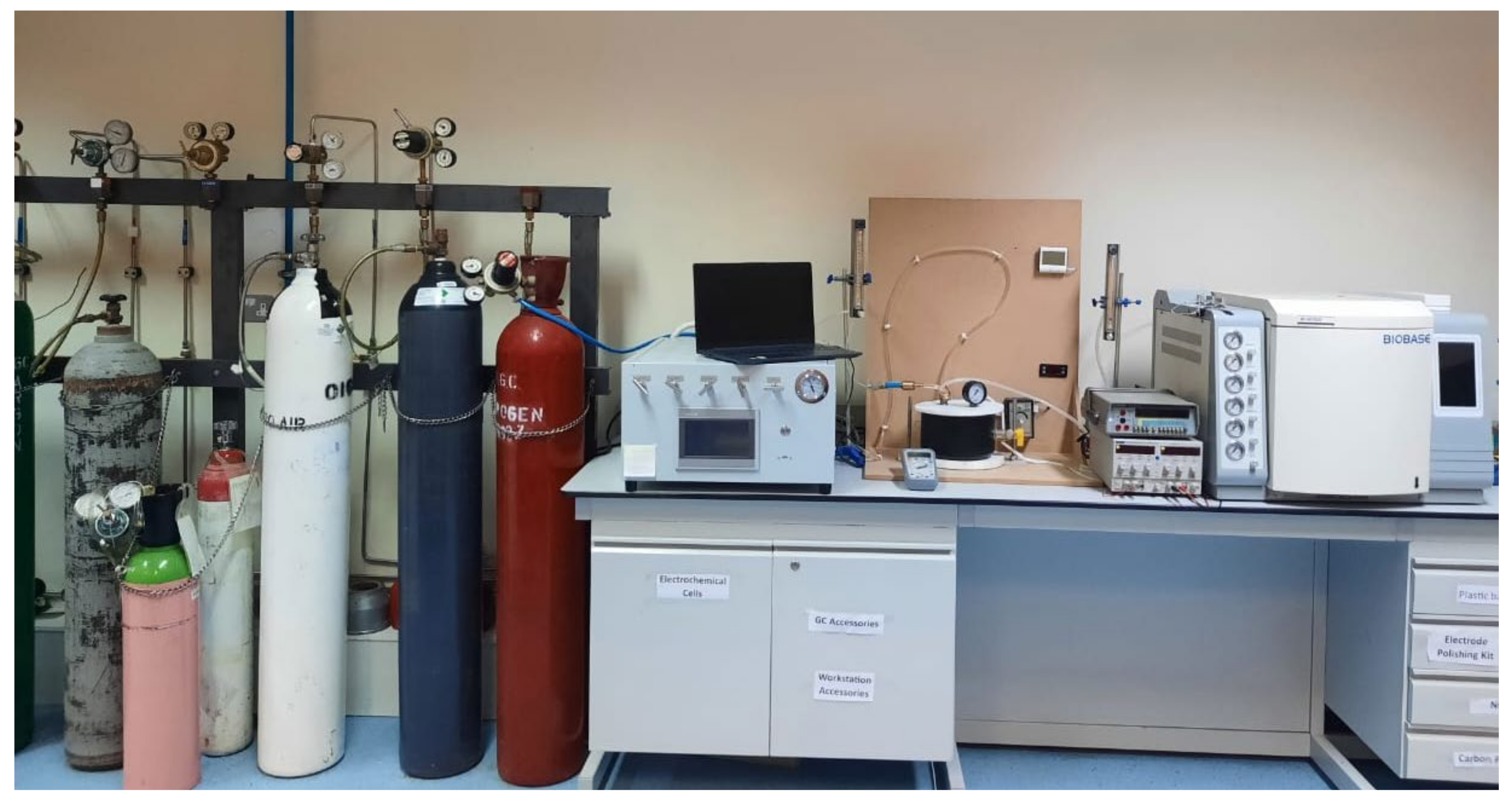
Following the preparation of the ZFC-coated cementitious disc described in Section 2.4, the H2 uptake of the composite was measured using a laboratory-scale PTFE (Teflon) flow-through gas micro-chamber system operated under continuous H2 exposure, as illustrated in Figure 3. The exposure chamber had an internal volume of 1000 ± 5 mL and was equipped with a calibrated pressure gauge (0–4 MPa), one gas inlet connected to a mass flow controller, and one outlet directly linked to a gas concentration measurement line under strictly controlled flow conditions. The exposure chamber was equipped with an integrated electrical heating system as well as calibrated temperature and relative humidity sensors, allowing precise control of environmental conditions during the tests.
Each specimen was prepared in a coin-shaped geometry and placed directly on a conductive coil substrate inside the chamber. This configuration ensured uniform exposure of the active surface to the gas stream while enabling simultaneous electrical resistance monitoring during H2 sensing.
H2 gas was supplied from a certified gas cylinder and introduced into the chamber through a calibrated gas flowmeter system, allowing precise control of the gas concentration. All measurements were performed at a fixed H2 concentration of 10,000 ppm, while the electrical resistance of the sensing layer was continuously recorded during gas exposure and recovery using a digital multimeter connected to a data acquisition system. This concentration was selected to ensure stable and reproducible response transients during comparative thermo-hygrometric evaluation.
The sensor response was evaluated based on the relative change in electrical resistivity (Δρ/ρ0), derived from the measured resistance variation during H2 exposure and recovery with ρ0 corresponding to the baseline resistivity in the reference atmosphere. Response and recovery times (tres and trec) were determined as the time required for the signal to reach 95% of the total change following H2 introduction and nitrogen purging, respectively. All H2 sensing experiments were carried out under static conditions. H2 at the prescribed concentration was introduced into the sealed chamber, and the resistance signal was recorded until a steady-state response was achieved. Subsequently, the outlet was opened and nitrogen was introduced to purge the chamber and restore the baseline state. Measurements were conducted at operating temperatures of 24, 39, 52, and 72 °C and relative humidity levels of 32%, 56%, and 87%. Prior to each measurement cycle, the sensor was allowed to stabilize in the reference atmosphere to ensure a constant and reproducible baseline signal. For each temperature–humidity condition, measurements were performed using three independently prepared sensing specimens, and each specimen was evaluated over three repeated sensing cycles under identical operating conditions.

2.6.2. Data Driven Prediction of H2 Concentration

For the development of the machine learning model for H2 sensing, a dynamic gas exposure protocol was adopted to generate a sufficiently dense and continuous dataset suitable for supervised learning. Indeed, unlike the closed or static exposure protocol employed in the experimental H2 sensing section primarily to characterize response time, a dynamic concentration ramp was applied here to increase the number of labelled data points available for model training. During each test, the inlet H2 concentration was continuously increased from baseline to a maximum value of 10,000 ppm following a controlled linear ramp of 0.1 sccm s−1 and subsequently decreased back to baseline using the same rate. This up–down concentration profile was repeated three consecutive times for each environmental condition and for each independently prepared specimen to capture cyclic behavior, improve statistical robustness, and reduce experimental variability. The dynamic variation of H2 concentration was achieved by progressively adjusting the H2 injection flow while maintaining a constant total carrier gas flow, resulting in an approximately linear concentration ramp inside the chamber. This dynamic protocol enabled the acquisition of a large number of coupled electrical–concentration data points across the full operating range.
All dynamic tests were conducted under twelve environmental conditions defined by four temperatures (24, 39, 52, and 72 °C, ±1 °C) and three relative humidity levels (32, 56, and 87%, ±3%), consistent with the conditions investigated in the experimental H2 sensing study. The input variables used for model development comprised the Δρ/ρ0, together with the corresponding temperature and relative humidity values. The model output was the instantaneous H2 concentration expressed in ppm, as measured in the gas line during dynamic exposure.
The dataset comprised all time-resolved data points acquired during the uptake experiments conducted under twelve distinct temperatures–humidity conditions. For each condition, the full temporal evolution of the electrical response and adsorption process was retained, resulting in approximately 1200 data points per condition. This approach ensured that both the transient adsorption regime and the progressive approach to saturation were adequately represented, enabling the model to capture the nonlinear relationship between electrical response, environmental conditions, and adsorption progress.
An extreme gradient boosting regression model (XGBoost) was employed due to its proven capability in handling nonlinear interactions, robustness against noise, and suitability for medium-sized experimental datasets. The model was implemented using an ensemble of 300 decision trees with a learning rate of 0.05 and a maximum tree depth of 4. Full subsampling of rows and features was applied, and the objective function was defined as squared error regression. This configuration provided an effective balance between predictive accuracy and generalization, while limiting overfitting associated with correlated time-series data.
Prior to model evaluation, the dataset was randomly partitioned into training (80%) and testing (20%) subsets to enable independent performance assessment on previously unseen data. Model performance was evaluated using five-fold cross-validation, where the model was trained on four subsets and validated on the remaining subset in each fold. In each fold, the model was trained on four subsets and validated on the remaining subset, and the predictive accuracy was quantified using the coefficient of determination (R2) and the root mean square error (RMSE). Following cross-validation, the final model was retrained using the complete dataset to generate predicted H2 concentration directly from the electrical response under varying temperature and humidity conditions. The residuals between predicted and measured values were analyzed to assess prediction bias and error distribution. The Python v 3.14.5 script and database used for model development are provided in Supplementary Materials to ensure full reproducibility.

3. Results and Discussion

3.1. ZFC Characterization

3.1.1. Structural Analysis by X-Ray Diffraction (XRD)

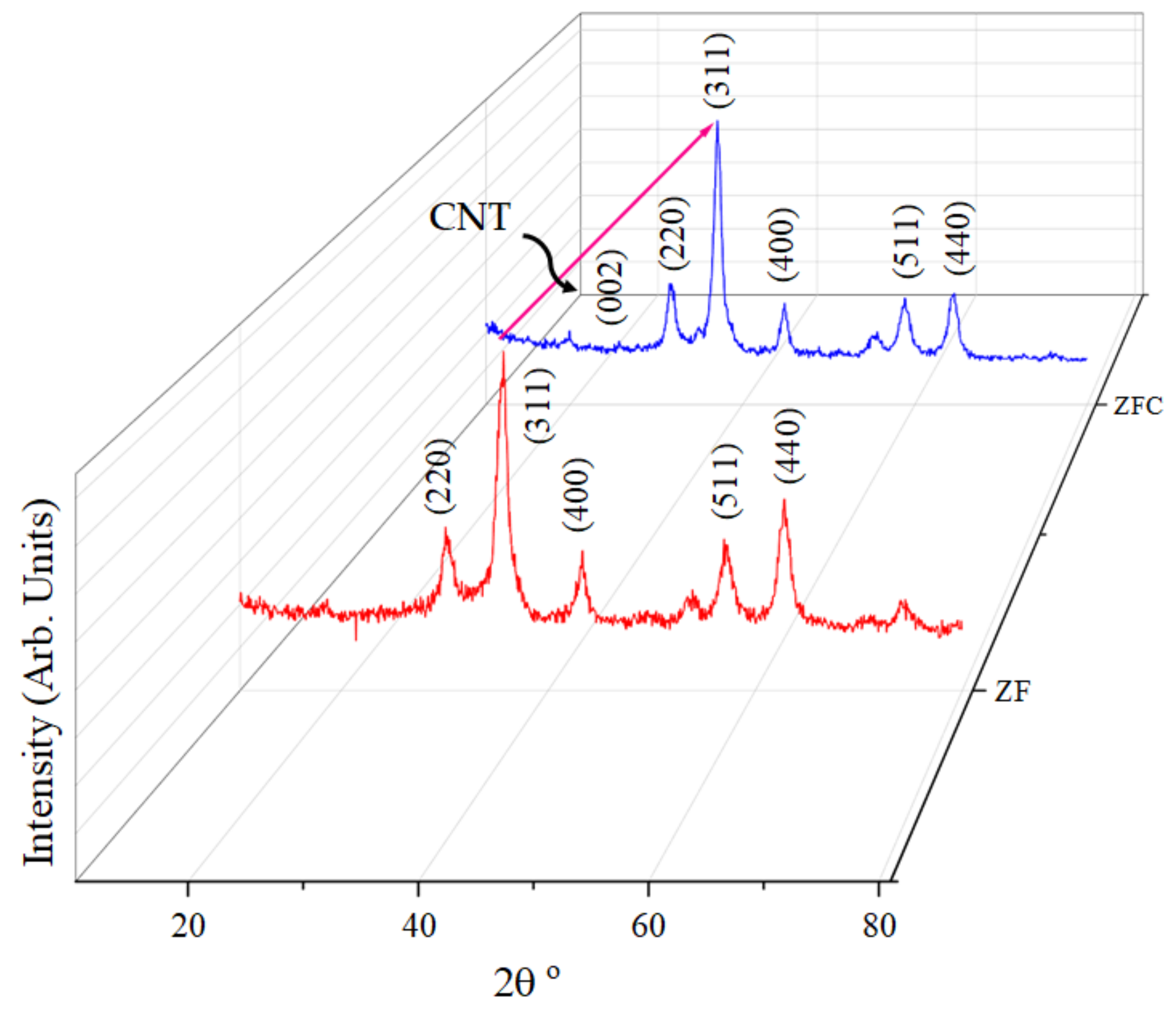
The crystal and phase structure of the initial ZF and the ZFC composite were investigated by X-ray diffraction, as shown in Figure 4. The diffraction pattern of the initial ZF exhibits the characteristic reflections of cubic spinel ZF, indexed to the (220), (311), (400), (511) and (440) crystal planes, consistent with the standard spinel ferrite structure (JCPDS No. 22-1012) and previous reports on ZF-based nanostructures [32,33]. The observed diffraction peaks at approximately 30°, 35°, 43°, 57°, and 62° correspond to the characteristic planes of cubic ZF and confirm the successful formation of the spinel phase without detectable secondary impurity phases [34]. The intensity of the (311) peak confirms the successful formation of ZF with good crystallinity [35]. The XRD pattern of the composite retains all the main peaks of ZF, indicating that the addition of CNTs does not change the basic structure of ZF. Also, the absence of additional impurity peaks attributed to crystalline secondary oxide phases indicates the phase purity of ZF [35,36].
A weak broad peak assigned to the (002) plane of graphitic carbon is observed in the composite pattern at around 2θ ≈ 26°. This reflection is characteristic of carbon nanotubes and is widely recognized as the main graphitic signature of CNT-containing composites [37,38]. Its relatively broad nature and low intensity are expected due to the low contribution of CNT to the stronger ferrite peaks. Therefore, the presence of the ~26° peak in ZFC, together with the ZF peaks, confirms the successful incorporation of CNTs into the ferrite matrix [39]. Another notable feature of the composite pattern is that the ZF peaks remain clearly distinguishable after the addition of CNTs, indicating that the ferrite phase maintains its crystallinity in the composite structure. Meanwhile, the slight decrease in the relative peak intensity and apparent broadening in the composite can be attributed to the presence of the carbon phase, the reduction of the effective diffraction volume of ZF, and the slight attenuation of the oxide peaks by the CNT network.

3.1.2. Morphological Analysis by FESEM

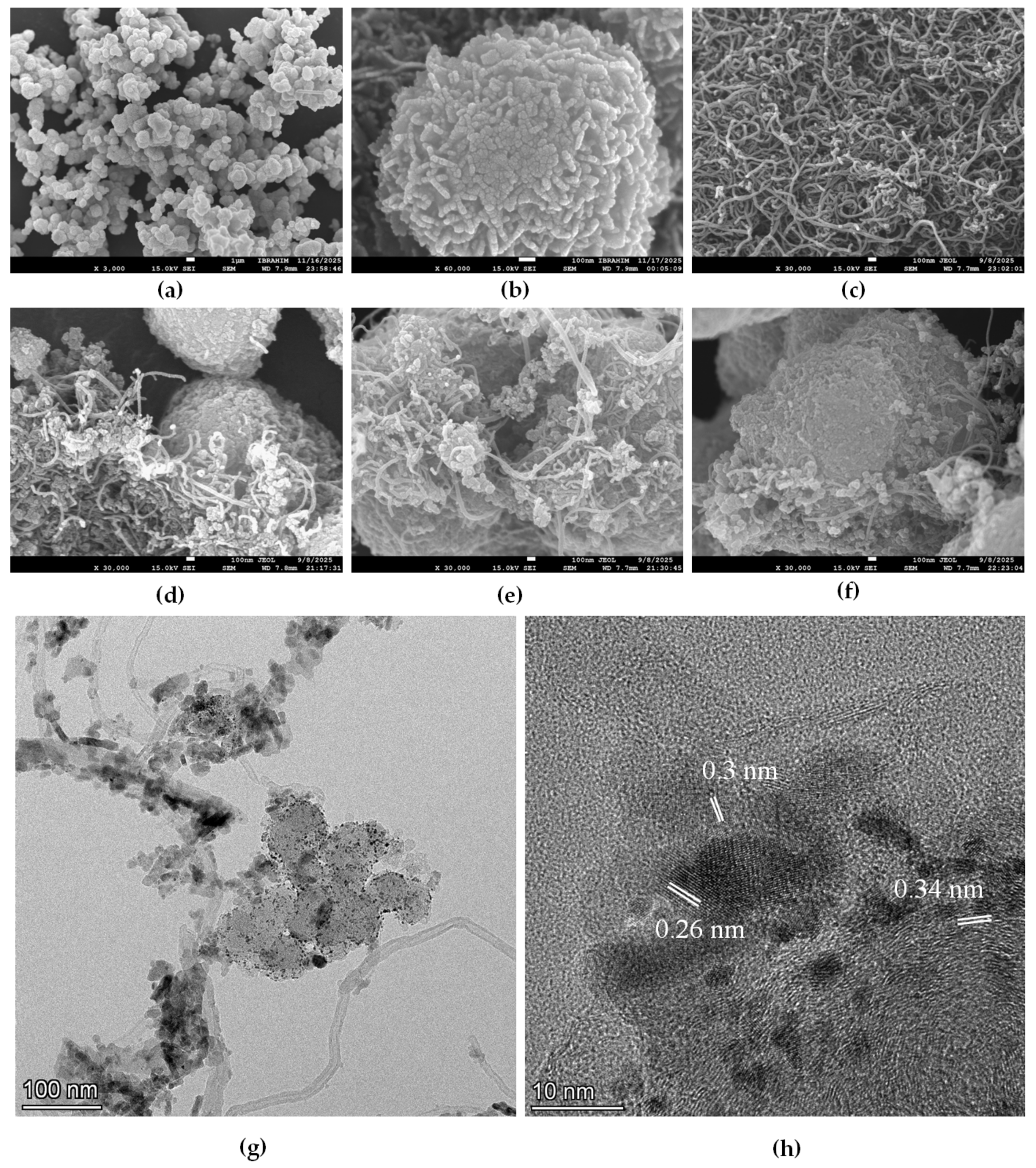
FESEM analysis was used to investigate the surface morphology of the initial ZF, CNTs and their composite, as shown in Figure 5a–f. The low magnification FESEM image of ZF (Figure 5a) shows the formation of dense microsphere assemblies composed of interconnected nanograins. These secondary structures exhibit a flower-like morphology with irregular clustering. At higher magnification (Figure 5b), the individual microspheres clearly show a hierarchical architecture made of dense nanoscale units [40]. Microspheres with a rough surface and high texture indicate the presence of abundant grain boundaries and interparticle voids [18]. Figure 5c shows the FESEM image of the initial MWCNTs, which are a highly intertwined and interconnected fibrous network with a uniform tubular morphology that forms a three-dimensional conductive scaffold. This type of morphology is characteristic of multi-walled carbon nanotubes and can provide a continuous diffusion path due to the high aspect ratio and extensive contacts between the tubes [41].
After MWCNT functionalization and composite formation (Figure 5d–f), the observed morphology confirms the successful integration of ZF microspheres with the MWCNT network. In Figure 5d, it is observed that the CNTs partially wrap around and bridge the adjacent ZF microspheres, creating initial surface contacts between the oxide phase and the carbon network. As nanoscale interfaces, the nanotubes can connect the discrete oxide particles and form conductive junctions. According to Figure 5e, the MWCNT network is uniformly distributed throughout the composite and penetrates into the interstices between the microspheres. The nanotubes form an interconnected network structure distributed across the rough oxide surface. The observed morphology suggests a relatively uniform distribution of the MWCNT network throughout the composite structure [42]. In Figure 5f, the composite exhibits a fully integrated hierarchical architecture with ZF microspheres embedded in a continuous MWCNT framework. The oxide particles maintain their spherical morphology without significant structural collapse, indicating that the composite formation process does not alter the microstructure of ZF. Also, the CNTs create a 3D network by providing conductive bridges across the microspheres.

3.1.3. Microstructural Analysis by TEM and HRTEM

To further investigate the microstructural features of the synthesized composite, TEM and HRTEM analyses were performed, as shown in Figure 5g,h. The low-magnification TEM image (Figure 5g) shows that the ZF component is composed of densely packed quasi-spherical nanoclusters composed of small primary nanoparticles. These clusters are non-uniformly distributed and partially attached to the MWCNT framework. The CNTs appear as elongated, translucent tubular structures that form a continuous and intertwined network throughout the composite. The close attachment of the ZF nanoparticles to the MWCNT surface confirms the successful formation of a ZF–CNT composite structure, in which the MWCNTs act as a structural scaffold supporting the dispersion of the oxide nanoparticles. Figure 5h provides a clear demonstration of the crystalline nature of the composite. The well-defined lattice fringes with interplanar spacings of approximately 0.30 nm and 0.26 nm are attributed to the (220) and (311) ZF crystal planes. These values are in excellent agreement with standard crystallographic data (JCPDS No. 22-1012) and confirm that the spinel structure is retained after the composite is formed [40]. In addition, lattice spacings with an interlayer spacing of approximately 0.34 nm are observed, which corresponds to the (002) plane of graphitic carbon and is a characteristic feature of CNTs. The simultaneous observation of ZF lattice planes and graphitic CNT layers confirms the formation of a fully integrated heterogeneous structure at the nanoscale [41]. Overall, the oxide nanoparticles are uniformly distributed along the CNT surface, without any large-scale phase separation or isolated bulk oxide domains. The close proximity between ZF nanocrystals and CNTs indicates the formation of close interfacial contact, which is essential for structural integration in ZF–CNT nanocomposites.

3.1.4. Elemental Composition and Mapping Analysis

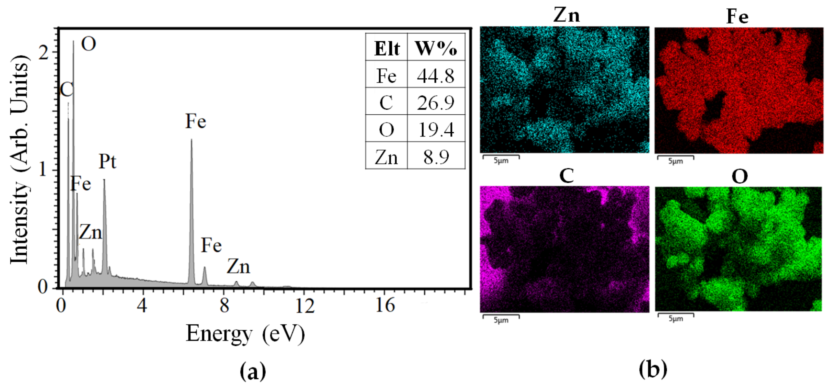
Energy dispersive X-ray spectroscopy was used to confirm the elemental composition and elemental maps were used to evaluate the spatial distribution of constituent elements in the ZFC composite structure. As shown in Figure 6a, the EDS spectrum shows characteristic peaks of Fe, Zn, O and C, confirming the coexistence of zinc ferrite and carbon nanotube phase in the synthesized composite. The simultaneous detection of Zn and Fe along with O is consistent with the formation of the ZF oxide phase, while the characteristic C signal originates from the CNT framework incorporated in the composite [22].
A distinct Pt signal is also observed in the spectrum; however, this peak is not included in the quantitative table because it originates from the Pt coating used during the EDS measurement. In addition, the weak peak observed near ~1.5 keV is also attributed to Pt-related signals originating from the conductive Pt coating applied prior to FESEM/EDS analysis. Therefore, the quantitative discussion was limited to Fe, C, O, and Zn to avoid overinterpretation of an outlier signal [43]. Quantitative data indicate that Fe is identified as the dominant metal species, followed by C, O, and Zn. This trend is qualitatively consistent with the presence of ferrite-rich regions connected to a carbon network [43].
The elemental mapping results in Figure 6b further confirm the successful formation of the composite. The Zn, Fe, and O maps show a clear co-localization within the same particle domains, consistent with the distribution of the ZF phase throughout the oxide-rich regions. In contrast, map C shows a broader and more continuous distribution, consistent with the CNT network surrounding, connecting, and supporting the oxide aggregates. This complementary distribution pattern indicates that the ZF is dispersed in close association with the CNT framework [43,44].

3.1.5. Surface Area and Pore Structure Analysis

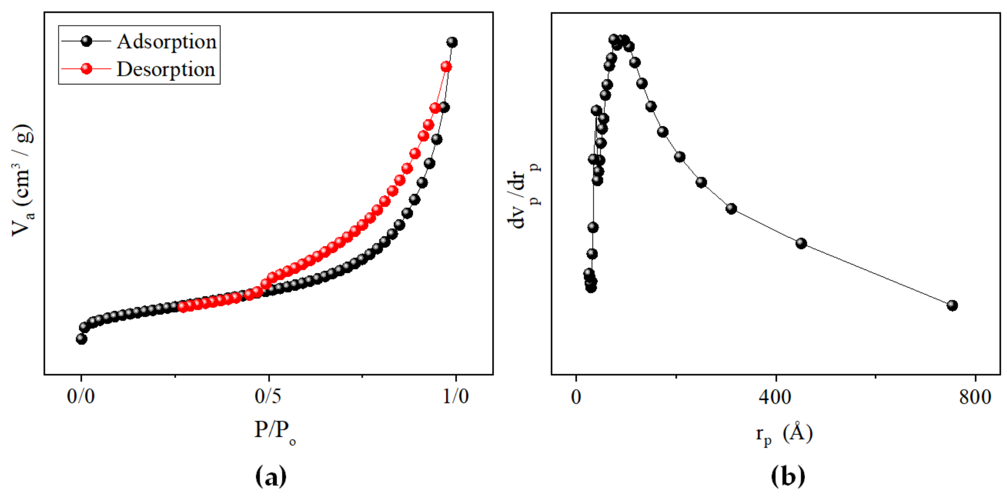
Nitrogen adsorption–desorption analysis was performed to evaluate the textural properties of the ZFC composite. As shown in Figure 7a, the isotherm exhibits a typical type IV profile with a distinct hysteresis loop, indicating the presence of a mesoporous structure [45]. BET analysis shows a specific surface area of 138.18 m2/g, a total pore volume of 0.00924 cm3/g and an average pore diameter of 89 nm. These values indicate that the synthesized composite has an expanded accessible surface area along with measurable pore volume. The relatively large average pore diameter indicates that in addition to mesopores, the structure includes wider interparticle pores resulting from the aggregation of ZF nanoparticles and the structure created by the CNT network. The pore size distribution (Figure 7b) confirms that the system has pores in the mesopore range with a broad distribution extending towards larger pore sizes. The MWCNT framework plays a key role in preventing the agglomeration of the oxide phase, which promotes the formation of a network of interconnected pores by maintaining the intergranular spacing. Overall, the BET results confirm that the ZFC composite is a hierarchical porous structure with significant surface accessibility and interconnected pore channels, which is consistent with the microstructural features observed in FESEM and TEM analyses.

3.2. H2 Sensing Performance

3.2.1. Effect of Operating Temperature and Relative Humidity on H2 Sensing Performance

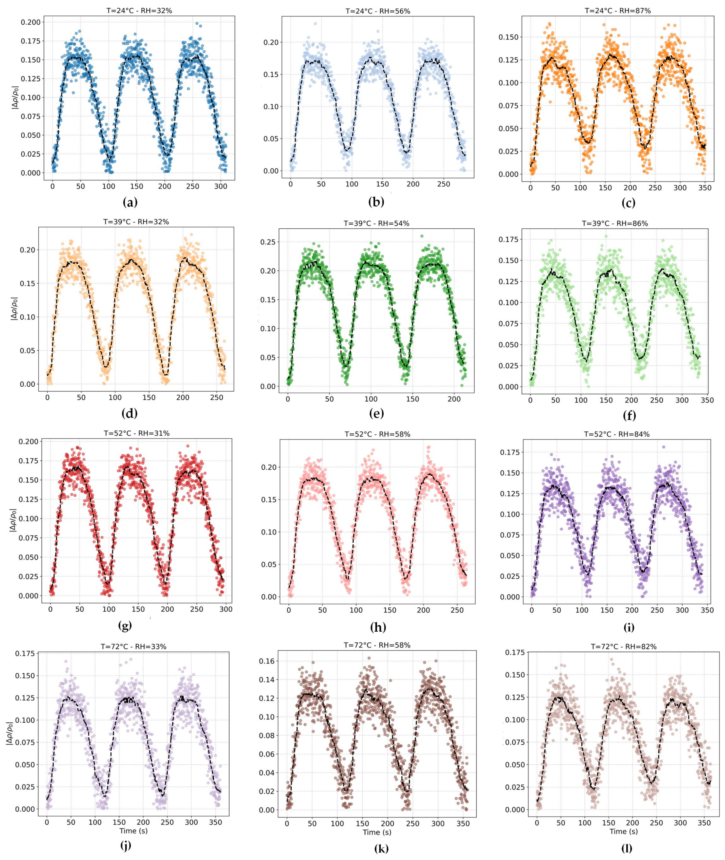
Figure 8a–l shows the H2 sensing behavior of the ZFC composite under temperature (24–72 °C) and relative humidity (≈32–87%) conditions toward 10,000 ppm H2. In all operating modes, the sensor exhibits a highly repeatable cyclic characteristic with well-defined absorption and recovery branches, indicating stable electrical readout and reversible gas–surface interactions during repeated exposure–recovery cycles operations [14]. When comparing the plots at constant humidity, a temperature-dependent change in the response is observed. At low temperature (24 °C; Figure 8a–c), the response is of moderate magnitude and characterized by broader transitions, indicating limited activation of the surface reaction kinetics and slower charge transfer across the heterogeneous ZFC interface. Increasing the operating temperature to 39 °C (Figure 8d–f) leads to a significant increase in the response value and clearer dynamic characteristics, indicating accelerated adsorption-reaction processes and improved interfacial charge exchange. The response reaches its maximum at an intermediate temperature of ≈39–52 °C (Figure 8d–i), where an optimal balance between surface reaction kinetics on the spinel oxide and efficient charge transport through the conductive CNT network is achieved [46]. At high temperature (72 °C; Figure 8j–l), despite faster transient slopes, a systematic decrease in response values is observed. This decrease is attributed to the reduced surface residence time of adsorbed H2-derived species and the accelerated desorption of reactive oxygen ions, which reduces the steady-state surface coverage and weakens the net modulation of the composite conductivity. Such non-uniform behavior and optimum temperature are a well-known feature of H2 chemoresistive sensors and indicate a competition between activated surface reactions and temperature-induced desorption [46,47]. Similar temperature-dependent response maxima have been reported for spinel-based H2 sensors, such as CuFe2O4 thin films, where an optimal operating window near moderate temperatures was attributed to the competition between surface reaction kinetics and thermally activated desorption processes [48].
In the investigated temperature and humidity range, the sensor exhibits repeatable dynamic transients with characteristic tres and trec of about a few tens of seconds. A quantitative summary of the response times extracted from the dynamic transients is provided in Table 1, showing that the fastest response occurs at intermediate temperatures (39–52 °C), while both lower and higher temperatures lead to slower kinetics. This behavior indicates enhanced kinetics of surface oxidation-reduction reactions and more efficient interfacial charge transfer at high temperatures. At higher temperatures and under higher humidity, the dynamic response becomes progressively slower, which can be attributed to the reduction of the surface residence time of reactive species and competitive adsorption by water molecules that hinder gas diffusion and interfacial charge exchange [46,49].
To investigate the effect of humidity, the behavior of the sensing layer was investigated at a constant temperature with increasing RH. At each temperature, increasing RH from ≈32% to ≈82–87% resulted in a gradual decrease in the response amplitude and an increase in the point-to-point signal dispersion. This behavior is attributed to the competitive adsorption of H2O molecules, which, by forming hydroxylated surface layers on ZF, reduce the active adsorption sites and thus prevent the interaction between H2 and surface oxygen species. In CNT/oxide composite systems, the adsorbed water also disrupts the local charge distribution in the CNT matrix, leading to greater sensing fluctuations [50]. Comparable humidity-induced attenuation without loss of reversibility has been widely observed in conducting CNT–assisted H2 sensors, where water adsorption perturbs local charge transport while preserving the underlying chemiresistive mechanism [51]. From a mechanistic perspective, the sensing response under low-to-moderate humidity conditions is primarily governed by adsorption-induced surface redox kinetics and interfacial charge-transfer processes at the ZF–CNT interface [46,49]. As the relative humidity increases, diffusion-related limitations become progressively more significant due to the formation of adsorbed water layers and hydroxylated surface species, which partially hinder effective H2 access to active reaction sites [48]. Therefore, the observed humidity-dependent response attenuation is attributed to the coupled influence of competitive adsorption, modified charge-transfer dynamics, and localized diffusion constraints near the active sensing surface [50]. It is noteworthy that although humidity reduces the absolute response, the cyclic reversibility and proportional response path are well preserved at all RH levels, highlighting the strength of the heterogeneous ZF-CNT coupling [50]. Moisture-induced degradation without catastrophic loss of reversibility has been widely reported for CNT-assisted H2 sensors and is generally considered to be characteristic of competitive physical adsorption processes, rather than irreversible chemical ones [50]. From a mechanistic perspective, the observed trend suggests a synergistic coupling between oxide-induced surface chemistry and CNT-mediated charge transfer. At the optimal temperature, the ZF microspheres provide abundant and accessible adsorption sites and rapid surface redox activity, while the CNT phase ensures efficient charge diffusion and enhancement of surface reactions to measurable resistance changes. Excessive temperature or high humidity disrupts this synergy by reducing effective gas adsorption or blocking active sites, respectively—effects that are fully consistent with previous reports on spinel/polymer H2 sensor systems [52,53,54,55]. It should be noted that the proposed sensing mechanism is based on qualitative interpretation of the experimentally observed sensing behavior together with established chemiresistive mechanisms commonly reported for ferrite/CNT composite systems. A more quantitative mechanistic understanding would require dedicated operando and interfacial characterization techniques, such as impedance spectroscopy or in situ surface-state analysis under controlled gas exposure conditions, which remain important directions for future investigation.

3.2.2. Data Driven Prediction of H2 Concentration

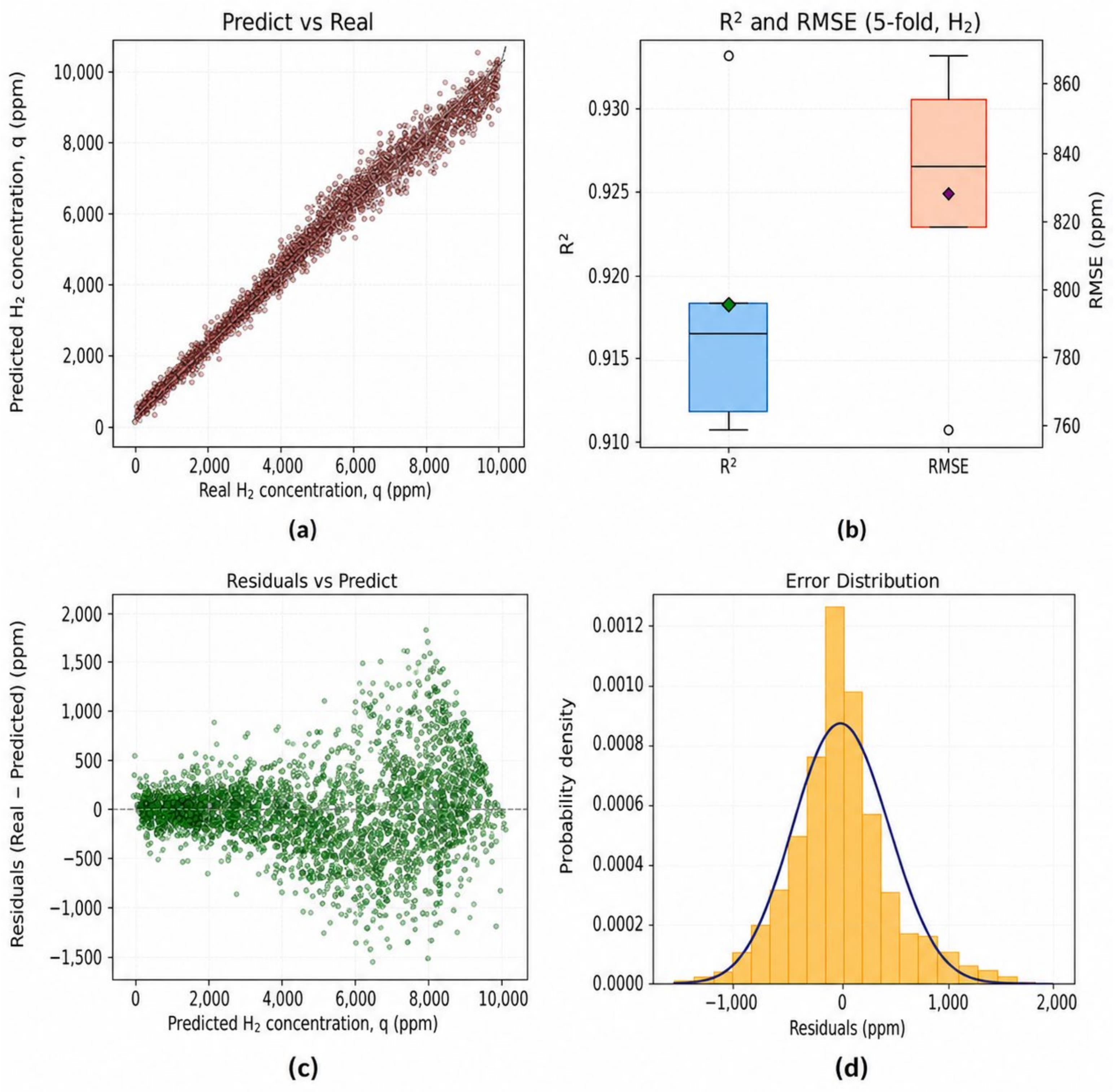
Figure 9 summarizes the performance of the XGBoost regression model used to infer the instantaneous H2 concentration from the dynamically acquired sensing data (Supplementary Materials), using the ramp protocol described before. As shown in the parity plot (Figure 9a), the predicted concentrations closely follow the 1:1 line over the full range from baseline to 10,000 ppm, with only a modest spread around the diagonal at the highest levels. This qualitative impression is confirmed by the five-fold cross-validation statistics in Figure 9b, where the distribution of R2 values is narrowly centered around ≈0.92 (≈0.91–0.93 across folds) and the corresponding RMSE lies at ≈820 ppm with a spread of roughly 760–860 ppm. In other words, the model reproduces the experimental H2 concentration with a typical absolute error of ≈8% of full scale, which is comparable to or better than the accuracy commonly reported for machine-learning-assisted gas-concentration prediction from chemiresistive sensor signals.
The residual analysis in Figure 9c,d provides further insight into the quality of the fit. Plotting the residuals versus the predicted concentration reveals an approximately symmetric cloud around zero up to ≈5000 ppm, with no systematic trend, indicating that the model remains essentially unbiased in the low-to-intermediate concentration range. At higher levels (≥7000 ppm), the spread of errors increases and a slight negative shift appears, i.e., a tendency to underpredict the largest concentrations. This behavior is consistent with the gradual onset of response saturation and non-linearity in the sensing layer, combined with the fact that fewer data points are available near the upper end of the dynamic ramp. The histogram of residuals in Figure 9c is well approximated by a unimodal, nearly Gaussian distribution centered close to zero, with most errors confined within ±1500 ppm. The absence of heavy tails or multiple modes suggests that the remaining discrepancy is dominated by experimental noise, intrinsic variability in the transient response under ramped exposure and the finite expressive capacity of the surrogate, rather than by unmodelled structure such as regime changes or hysteresis.
When benchmarked against the broader literature on data-driven gas-concentration prediction, the present results are in line with or superior to typical performances. Neural-network-based models applied to H2 detection in sensor arrays commonly achieve average relative errors on the order of 5–10%, depending on the number of sensing elements and environmental compensation [56]. More recent works that combine tree-based ensembles with deep architectures (e.g., 1DCNN–XGBR hybrids) for toxic-gas and H2S concentration prediction report R2 values around 0.90–0.95, with RMSE values comparable to the intrinsic scatter of the training data [57]. Similar ranges are observed in stacked or optimized XGBoost models developed for hydrogen-related properties and gas-emission forecasting, where gradient-boosting consistently outperforms linear and shallow models in terms of generalization error [58,59]. Within this context, the R2 ≈ 0.92 and RMSE ≈ 820 ppm obtained here are comparable to representative performances reported for ML-assisted gas-concentration prediction under controlled sensing conditions, particularly considering that the present framework relies on a single chemiresistive sensing element operated under realistic dynamic exposure rather than on large sensor arrays or highly idealized step-wise protocols.
From an application perspective, such a surrogate has direct implications for real-time H2 monitoring. An accurate data-driven mapping from sensor output to concentration enables virtual calibration layers that can correct for non-linearity and moderate drift, and can be embedded into embedded hardware or edge computing platforms for on-the-fly concentration estimation and alarm triggering. In addition, the present model provides a quantitative baseline upon which more advanced schemes—such as physics-informed boosting, multi-sensor sensor-fusion or SHAP-based interpretability analyses—can be built to explicitly disentangle the influence of operating temperature, humidity and dynamic ramp parameters on the reconstructed H2 concentration, as recently advocated for chemiresistive gas-sensor modelling. This combination of experimentally grounded dynamic sensing and high-fidelity regression therefore supports the development of intelligent H2-sensing architectures in which ZFC-based coatings act not only as passive chemiresistors but as fully integrated smart nodes within larger monitoring systems. Although the predictive performance of the XGBoost model was satisfactory, the dataset remains experimentally bounded and partially correlated due to the transient nature of the sensing measurements. While cross-validation and conservative hyperparameter selection were used to reduce overfitting risk, future studies should incorporate larger datasets, independent external validation, and broader operational conditions to further evaluate model generalization and robustness.

4. Conclusions

This study introduced a surface-integrated ZnFe2O4–MWCNT (ZFC) composite coating as a proof-of-concept, potentially retrofit-compatible sensing approach capable of enabling hydrogen-responsive functionality on cementitious materials, addressing some limitations associated with discrete point-based sensing systems. While the present work experimentally demonstrates sensing performance on laboratory-scale coated specimens, the proposed coating architecture and deposition strategy provide a potential pathway toward scalable surface-integrated hydrogen sensing systems. The proposed system combines a redox-active spinel oxide with a conductive MWCNT network to enable effective chemiresistive sensing, while remaining compatible with scalable surface-deposition techniques and real structural substrates. The results demonstrated that:
  • The XRD, FESEM, and TEM analyses confirmed the formation of a crystalline spinel ZF phase integrated within a continuous MWCNT network.
  • The ZFC composite exhibited a hierarchical porous structure with a specific surface area of 138.18 m2/g, promoting enhanced gas diffusion and accessible active sites, which are critical for achieving stable and repeatable sensing under practical conditions.
  • The sensor showed optimal hydrogen sensing performance at 39–52 °C with a minimum response time of 18 s, while the response time increased to approximately 40.5 s under higher-temperature conditions (72 °C), indicating the strong influence of thermo-hygrometric conditions on adsorption–desorption kinetics and charge-transfer efficiency.
  • Increasing relative humidity from 32% to 87% reduced the response amplitude but preserved reversible cyclic behavior throughout repeated exposure–recovery operations, demonstrating robustness of the sensing mechanism under realistic environmental fluctuations encountered in field applications.
  • The dynamic concentration-ramp experiments demonstrated stable and reversible hydrogen sensing behavior from near-baseline levels up to 10,000 ppm H2 under twelve thermo-hygrometric operating conditions and ramp rates of 0.1 sccm s−1, while the maximum normalized resistance variation reached approximately 0.12 under low-humidity conditions and decreased to about 0.07–0.08 at high relative humidity levels.
  • The XGBoost model achieved high predictive accuracy (R2 ≈ 0.92, RMSE ≈ 820 ppm), with most residual prediction errors remaining within ±1500 ppm and without significant multimodal error distribution, supporting reliable real-time estimation of hydrogen concentration from sensor signals.
This work establishes a stepping stone toward transforming passive infrastructure into active sensing systems, positioning surface-functionalized coatings as a viable alternative to device-level hydrogen sensors.

5. Limitations and Future Perspectives

The present study demonstrates a proof-of-concept framework for surface-integrated hydrogen sensing using ZFC-coated cementitious specimens under controlled thermo-hygrometric conditions. Although the sensing response is governed by localized gas–surface redox interactions and CNT-mediated charge transport mechanisms that are not inherently dependent on specimen dimensions, the current work does not experimentally validate large-area spatial sensing performance or distributed signal uniformity. In addition, low-concentration detection performance, cross-sensitivity effects, and long-term sensing stability were beyond the scope of the present study. Future research should therefore focus on large-area implementation, spatially resolved sensing behavior, low-concentration sensitivity assessment, and advanced data-driven strategies for practical infrastructure-integrated hydrogen monitoring. Furthermore, the long-term adhesion and mechanical reliability of the coating under realistic service conditions remain to be systematically evaluated. Future studies should also investigate the influence of potential interfering gases, including CH4, CO, NH3, and volatile organic compounds, to further evaluate the selectivity and practical applicability of the proposed sensing system under multi-gas operational environments. Although dynamic concentration-ramp experiments included the low-concentration regime, the present study did not specifically focus on a formal quantitative determination of the detection limit based on standardized signal-to-noise criteria. Future work will further investigate low-concentration calibration and statistical detection-threshold analysis to establish the practical limit of detection of the proposed sensing system.

Supplementary Materials

The following supporting information can be downloaded at: https://www.mdpi.com/article/10.3390/c12020051/s1, The Python Script Used for Model Development and H2 Dynamic Sensing Data (Section 3.2.2).

Author Contributions

Conceptualization, M.A. and Z.A.; methodology, M.A.; software, M.A., Z.A. and E.F.; validation, M.A., Z.A. and E.F.; formal analysis, M.A. and Z.A.; investigation, M.A.; resources, M.A. and Z.A.; data curation, M.A. and Z.A.; writing—original draft preparation, M.A., Z.A. and E.F.; writing—review and editing, M.A. and Z.A.; visualization, M.A.; supervision, M.A.; project administration, M.A.; funding acquisition. All authors have read and agreed to the published version of the manuscript.

Funding

This research was funded in whole or in part by the Fundação para a Ciência e a Tecnologia, I.P. (FCT, https://ror.org/00snfqn58) under Grant UID/6438/2025 (https://doi.org/10.54499/UID/06438/2025) of the research unit CERIS. For the purpose of Open Access, the author has applied a CC-BY public copyright license to any Author’s Accepted Manuscript (AAM) version arising from this submission.

Data Availability Statement

All Python v 3.14.5 scripts and the complete experimental and modelling datasets are provided in Supplementary Materials to ensure full reproducibility.

Conflicts of Interest

The authors declare no conflicts of interest.

References

  1. Abohamzeh, E.; Salehi, F.; Sheikholeslami, M.; Abbassi, R.; Khan, F. Review of hydrogen safety during storage, transmission, and applications processes. J. Loss Prev. Process Ind. 2021, 72, 104569. [Google Scholar] [CrossRef] [Scilit]
  2. Rostrup-Nielsen, J.R.; Rostrup-Nielsen, T. Large-scale hydrogen production. Cattech 2002, 6, 150–159. [Google Scholar] [CrossRef] [Scilit]
  3. Marzouk, O.A. Expectations for the role of hydrogen and its derivatives in different sectors through analysis of the four energy scenarios: IEA-STEPS, IEA-NZE, IRENA-PES, and IRENA-1.5 °C. Energies 2024, 17, 646. [Google Scholar] [CrossRef] [Scilit]
  4. Jeon, J.; Kim, S.J. Recent progress in hydrogen flammability prediction for the safe energy systems. Energies 2020, 13, 6263. [Google Scholar] [CrossRef] [Scilit]
  5. Rivkin, C.H.; Burgess, R.M.; Buttner, W.J. Hydrogen Technologies Safety Guide; National Renewable Energy Laboratory: Applewood, CO, USA, 2015. [Google Scholar]
  6. Hübert, T.; Boon-Brett, L.; Black, G.; Banach, U. Hydrogen sensors–a review. Sens. Actuators B Chem. 2011, 157, 329–352. [Google Scholar] [CrossRef] [Scilit]
  7. Wadell, C.; Syrenova, S.; Langhammer, C. Plasmonic hydrogen sensing with nanostructured metal hydrides. ACS Nano 2014, 8, 11925–11940. [Google Scholar] [CrossRef] [Scilit]
  8. Shankar, P.; Rayappan, J.B.B. Gas sensing mechanism of metal oxides: The role of ambient atmosphere, type of semiconductor and gases-A review. Sci. Lett. J. 2015, 4, 126. [Google Scholar]
  9. Yamazoe, N. Toward innovations of gas sensor technology. Sens. Actuators B Chem. 2005, 108, 2–14. [Google Scholar]
  10. Kong, J.; Chapline, M.G.; Dai, H. Functionalized carbon nanotubes for molecular hydrogen sensors. Adv. Mater. 2001, 13, 1384–1386. [Google Scholar] [CrossRef] [Scilit]
  11. Sayago, I.; Santos, H.; Horrillo, M.C.; Aleixandre, M.; Fernández, M.J.; Terrado, E.; Tacchini, I.; Aroz, R.; Maser, W.K.; Benito, A.M.; et al. Carbon nanotube networks as gas sensors for NO2 detection. Talanta 2008, 77, 758–764. [Google Scholar] [CrossRef] [Scilit]
  12. Paska, Y.; Stelzner, T.; Christiansen, S.; Haick, H. Enhanced sensing of nonpolar volatile organic compounds by silicon nanowire field effect transistors. ACS Nano 2011, 5, 5620–5626. [Google Scholar] [CrossRef] [Scilit]
  13. Singh, V. An overview on recent trends of spinel ferrites (MFe2O4: M = Fe2, Co2, Mn2, Ni2, Zn2) synthesis and catalytic applications. Int. J. New Chem. 2025, 12, 283. [Google Scholar]
  14. Azmoodeh, Z.; Nasirian, S.; Moghaddam, H.M. Improving H2 gas sensing with ZnMn2O4/Polypyrrole Nanocomposite. Int. J. Hydrogen Energy 2024, 85, 854–864. [Google Scholar] [CrossRef] [Scilit]
  15. Azmoodeh, Z.; Karouei, S.F.H.; Khatibani, A.B.; Rezapour, A.; Moghaddam, H.M.; Nasirian, S. A stunning sensitive isopropanol gas sensor based on ZnMn2O4 microspheres. Phys. B Condens. Matter 2025, 698, 416752. [Google Scholar] [CrossRef] [Scilit]
  16. Zhang, R.; Qin, C.; Bala, H.; Wang, Y.; Cao, J. Recent progress in spinel ferrite (MFe2O4) chemiresistive based gas sensors. Nanomaterials 2023, 13, 2188. [Google Scholar] [CrossRef] [Scilit]
  17. Shiraz, H.G.; Astaraei, F.R.; Fardindoost, S.; Hosseini, Z.S. Decorated CNT based on porous silicon for hydrogen gas sensing at room temperature. RSC Adv. 2016, 6, 44410–44414. [Google Scholar] [CrossRef] [Scilit]
  18. Han, L.; Zhai, W.; Bai, B.; Zhu, H.; Yang, J.; Yan, Z.; Zhang, T. Critical behavior in Ni0.15Cu0.15 Zn0.7Fe2O4 spinel ferrite. Ceram. Int. 2019, 45, 14322–14326. [Google Scholar] [CrossRef] [Scilit]
  19. Ozbey, S.; Yerli, Y.; Erkmen, C.; Kurbanoglu, S. Recent Advances in Nanomaterial-Based Electrochemical Sensors for Pharmaceutical and Biomedical Diagnosis. In Fabrication and Advanced Applications of Nanomaterial-Based Electrochemical Sensors; CRC Press: Boca Raton, FL, USA, 2025; Volume 148. [Google Scholar]
  20. Zhang, W.; Yuan, T.; Wang, X.; Chen, Y.; Xu, J. ZnFe2O4@ZnO pn heterojunction based ultra-fast H2S sensor and mechanism: For detecting freshness of eggs. Sens. Actuators B Chem. 2026, 450, 139254. [Google Scholar]
  21. Achary, L.S.K.; Maji, B.; Kumar, A.; Ghosh, S.P.; Kar, J.P.; Dash, P. Efficient room temperature detection of H2 gas by novel ZnFe2O4–Pd decorated rGO nanocomposite. Int. J. Hydrogen Energy 2020, 45, 5073–5085. [Google Scholar] [CrossRef] [Scilit]
  22. Dang, H.; Qiu, Y.; Cheng, Z.; Yang, W.; Wu, H.; Fan, H.; Dong, X. Hydrothermal preparation and characterization of nanostructured CNTs/ZnFe2O4 composites for solar water splitting application. Ceram. Int. 2016, 42, 10520–10525. [Google Scholar] [CrossRef] [Scilit]
  23. Mir, S.; Akbarzadeh Torbati, N.; Amani, V.; Tajik, S.; Beitollahi, H. Y-Co metal-organic framework for sensitive electrochemical determination of doxorubicin hydrochloride. ADMET DMPK 2025, 13, 3141. [Google Scholar]
  24. Ullah, R. Semiconductor ZnFe2O4 as efficient photocatalyst for the degradation of organic dyes: An update. J. Chem. Rev. 2023, 5, 466–476. [Google Scholar]
  25. Andersen, H.L.; Granados-Miralles, C.; Jensen, K.M.Ø.; Saura-Muzquiz, M.; Christensen, M. The chemistry of spinel ferrite nanoparticle nucleation, crystallization, and growth. ACS Nano 2024, 18, 9852–9870. [Google Scholar] [CrossRef] [Scilit] [PubMed]
  26. Barandun, G.; Gonzalez-Macia, L.; Lee, H.S.; Dincer, C.; Guder, F. Challenges and opportunities for printed electrical gas sensors. ACS Sens. 2022, 7, 2804–2822. [Google Scholar] [PubMed]
  27. Abedi, M.; Fangueiro, R.; Correia, A.G. An effective method for hybrid CNT/GNP dispersion and its effects on the mechanical, microstructural, thermal, and electrical properties of multifunctional cementitious composites. J. Nanomater. 2020, 2020, 6749150. [Google Scholar] [CrossRef] [Scilit]
  28. Liu, H.; Wang, J.; Wang, J.; Cui, S. Sulfonitric Treatment of Multiwalled Carbon Nanotubes and Their Dispersibility in Water. Materials 2018, 11, 2442. [Google Scholar] [CrossRef] [Scilit]
  29. Lavagna, L.; Bartoli, M.; Suarez-Riera, D.; Cagliero, D.; Musso, S.; Pavese, M. Oxidation of carbon nanotubes for improving the mechanical and electrical properties of oil-well cement-based composites. ACS Appl. Nano Mater. 2022, 5, 6671–6678. [Google Scholar] [CrossRef] [Scilit]
  30. Datsyuk, V.; Kalyva, M.; Papagelis, K.; Parthenios, J.; Tasis, D.; Siokou, A.; Kallitsis, I.; Galiotis, C. Chemical oxidation of multiwalled carbon nanotubes. Carbon 2008, 46, 833–840. [Google Scholar] [CrossRef] [Scilit]
  31. EN 196-1; Methods of Testing Cement—Part 1: Determination of Strength. European Committee for Standardization (CEN): Brussels, Belgium, 2016.
  32. Yuvaraj, S.; Ramachandran, S.; Sheela, R.; Jothiramalingam, R.; Isaac, R.S.R.; Sundararajan, M.; Sasikumar, S. Synthesis and optical and magnetic property characterization of Zn1−x−yCoxNiyFe2O4 (x & y= 0, 0.05, 0.15 and 0.25) nanoparticles. J. Ovonic Res. 2025, 21, 279–284. [Google Scholar]
  33. Oliveira, T.P.; Marques, G.N.; Macedo Castro, M.A.; Viana Costa, R.C.; Rangel, J.H.G.; Rodrigues, S.F.; dos Santos, C.C.; Oliveira, M.M. Synthesis and photocatalytic investigation of ZnFe2O4 in the degradation of organic dyes under visible light. J. Mater. Res. Technol. 2020, 9, 15001–15015. [Google Scholar]
  34. Yalovega, G.E.; Brzhezinskaya, M.; Dmitriev, V.O.; Shmatko, V.A.; Ershov, I.V.; Ulyankina, A.A.; Chernysheva, D.V.; Smirnova, N.V. Interfacial interaction in MeOx/MWNTs (Me–Cu, Ni) nanostructures as efficient electrode materials for high-performance supercapacitors. Nanomaterials 2024, 14, 947. [Google Scholar] [CrossRef] [Scilit]
  35. Luo, J.; Wu, Y.; Jiang, M.; Zhang, A.; Chen, X.; Zeng, Y.; Wang, Y.; Zhao, Y.; Wang, G. Novel ZnFe2O4/BC/ZnO photocatalyst for high-efficiency degradation of tetracycline under visible light irradiation. Chemosphere 2023, 311, 137041. [Google Scholar] [CrossRef] [Scilit]
  36. Abedi, M.; Fangueiro, R.; Gomes Correia, A. Ultra-sensitive affordable cementitious composite with high mechanical and microstructural performances by hybrid CNT/GNP. Materials 2020, 13, 3484. [Google Scholar] [CrossRef] [Scilit]
  37. Awadallah-f, A.; Al-Muhtaseb, S. Carbon nanoparticles-decorated carbon nanotubes. Sci. Rep. 2020, 10, 4878. [Google Scholar] [CrossRef] [Scilit]
  38. Chen, Z.; Qu, Q.; Li, X.; Srinivas, K.; Chen, Y.; Zhu, M. Room-Temperature Synthesis of Carbon-Nanotube-Interconnected Amorphous NiFe-Layered Double Hydroxides for Boosting Oxygen Evolution Reaction. Molecules 2023, 28, 7289. [Google Scholar] [CrossRef] [Scilit] [PubMed]
  39. Singhal, S.; Sharma, R.; Singh, C.; Bansal, S. Enhanced photocatalytic degradation of methylene blue using ZnFe2O4/MWCNT composite synthesized by hydrothermal method. Indian J. Mater. Sci. 2013, 2013, 356025. [Google Scholar] [CrossRef] [Scilit]
  40. Zhao, H.; Wu, J.; Li, J.; Wu, H.; Zhang, Y.; Liu, H. A flexible three-dimensional MoS2/carbon architecture derived from melamine foam as free-standing anode for high performance lithium-ion batteries. Appl. Surf. Sci. 2018, 462, 337–343. [Google Scholar] [CrossRef] [Scilit]
  41. Chen, J.; Xiong, X.; Xiao, P.; Zhang, H.-B. The catalytic effect of boric acid on polyacrylonitrile-based carbon fibers and the thermal conductivity of carbon/carbon composites produced from them. Carbon 2010, 48, 2341–2346. [Google Scholar]
  42. Lipinska, M.; Hutchinson, J.M. Elastomeric epoxy nanocomposites: Nanostructure and properties. Compos. Sci. Technol. 2012, 72, 640–646. [Google Scholar] [CrossRef] [Scilit]
  43. Newbury, D.E.; Ritchie, N.W.M. Elemental mapping of microstructures by scanning electron microscopy-energy dispersive X-ray spectrometry (SEM-EDS): Extraordinary advances with the silicon drift detector (SDD). J. Anal. At. Spectrom. 2013, 28, 973–988. [Google Scholar] [CrossRef] [Scilit]
  44. Al Khabouri, S.; Al Harthi, S.; Maekawa, T.; Nagaoka, Y.; Elzain, M.E.; Al Hinai, A.; Al-Rawas, A.D.; Gismelseed, A.M.; Yousif, A.A. Composition, electronic and magnetic investigation of the encapsulated ZnFe2O4 nanoparticles in multiwall carbon nanotubes containing Ni residuals. Nanoscale Res. Lett. 2015, 10, 262. [Google Scholar] [CrossRef] [Scilit] [PubMed]
  45. Buttersack, C. Modeling of type IV and V sigmoidal adsorption isotherms. Phys. Chem. Chem. Phys. 2019, 21, 5614–5626. [Google Scholar] [CrossRef] [Scilit] [PubMed]
  46. Koo, W.-T.; Cho, H.-J.; Kim, D.-H.; Kim, Y.H.; Shin, H.; Penner, R.M.; Kim, I.-D. Chemiresistive Hydrogen Sensors: Fundamentals, Recent Advances, and Challenges. ACS Nano 2020, 14, 14284–14322. [Google Scholar] [CrossRef] [Scilit] [PubMed]
  47. Darmadi, I.; Nugroho, F.A.A.; Langhammer, C. High-performance nanostructured palladium-based hydrogen sensors—Current limitations and strategies for their mitigation. ACS Sens. 2020, 5, 3306–3327. [Google Scholar] [CrossRef] [Scilit]
  48. Haija, M.A.; Ayesh, A.I.; Ahmed, S.; Katsiotis, M.S. Selective hydrogen gas sensor using CuFe2O4 nanoparticle based thin film. Appl. Surf. Sci. 2016, 369, 443–447. [Google Scholar] [CrossRef] [Scilit]
  49. Tan, Y.; Du, B.; Liang, C.; Guo, X.; Zheng, H.; Liu, P.; Yang, X.; Li, S.; Jin, B.; Sun, J. Improving anti-humidity property of a SnO2-based chemiresistive hydrogen sensor by a breathable and hydrophobic fluoropolymer coating. Langmuir 2022, 38, 13833–13840. [Google Scholar] [CrossRef] [Scilit]
  50. Herbeck-Tazibt, J.; Djeziri, M.A.; Fiorido, T.; Seguin, J.-L. Review of Hydrogen Sensors in Aerobic and Anaerobic Environments Coupled with Artificial Intelligence Tools. Sensors 2025, 25, 6936. [Google Scholar] [CrossRef] [Scilit]
  51. Li, W.; Jang, D.M.; An, S.Y.; Kim, D.; Hong, S.-K.; Kim, H. Polyaniline–chitosan nanocomposite: High performance hydrogen sensor from new principle. Sens. Actuators B Chem. 2011, 160, 1020–1025. [Google Scholar] [CrossRef] [Scilit]
  52. Dong, R.; Yang, M.; Zuo, Y.; Liang, L.; Xing, H.; Duan, X.; Chen, S. Conducting Polymers-Based Gas Sensors: Principles, Materials, and Applications. Sensors 2025, 25, 2724. [Google Scholar] [CrossRef] [Scilit]
  53. Askar, P.; Kanzhigitova, D.; Ospanova, A.; Tapkharov, A.; Duisenbekov, S.; Abutalip, M.; Soltabayev, B.; Turlybekuly, A.; Adilov, S.; Nuraje, N. 1 ppm-detectable hydrogen gas sensor based on nanostructured polyaniline. Sci. Rep. 2024, 14, 26984. [Google Scholar] [CrossRef] [Scilit]
  54. Shooshtari, M.; Salehi, A.; Vollebregt, S. Effect of humidity on gas sensing performance of carbon nanotube gas sensors operated at room temperature. IEEE Sens. J. 2020, 21, 5763–5770. [Google Scholar] [CrossRef] [Scilit]
  55. Shooshtari, M.; Salehi, A. An electronic nose based on carbon nanotube-titanium dioxide hybrid nanostructures for detection and discrimination of volatile organic compounds. Sens. Actuators B Chem. 2022, 357, 131418. [Google Scholar] [CrossRef] [Scilit]
  56. Tomeček, D.; Moberg, H.K.; Nilsson, S.; Theodoridis, A.; Darmadi, I.; Midtvedt, D.; Volpe, G.; Andersson, O.; Langhammer, C. Neural network enabled nanoplasmonic hydrogen sensors with 100 ppm limit of detection in humid air. Nat. Commun. 2024, 15, 1208. [Google Scholar] [CrossRef] [Scilit]
  57. Yue, J.; Wu, F.; Wang, X.; Feng, P.; Zhuo, J.; Cui, H.; Yan, J.; Duan, S.; Peng, X. A Novel Method for H2S Concentration Prediction Under Small Sample Based on ECA-1DCNN-XGBR. IEEE Sens. J. 2024, 24, 20167–20176. [Google Scholar] [CrossRef] [Scilit]
  58. Champahom, T.; Banyong, C.; Janhuaton, T.; Se, C.; Watcharamaisakul, F.; Ratanavaraha, V.; Jomnonkwao, S. Deep Learning vs. Gradient Boosting: Optimizing Transport Energy Forecasts in Thailand Through LSTM and XGBoost. Energies 2025, 18, 1685. [Google Scholar] [CrossRef] [Scilit]
  59. Adam, A.M.; Osman, A.N.; Yusuf, A.M.; Gokcekus, H.; Bolour, F. Exploring machine learning models for predicting greenhouse gas emissions in Africa’s building sector: A case study of six nations. Environ. Syst. Res. 2025, 14, 21. [Google Scholar] [CrossRef] [Scilit]
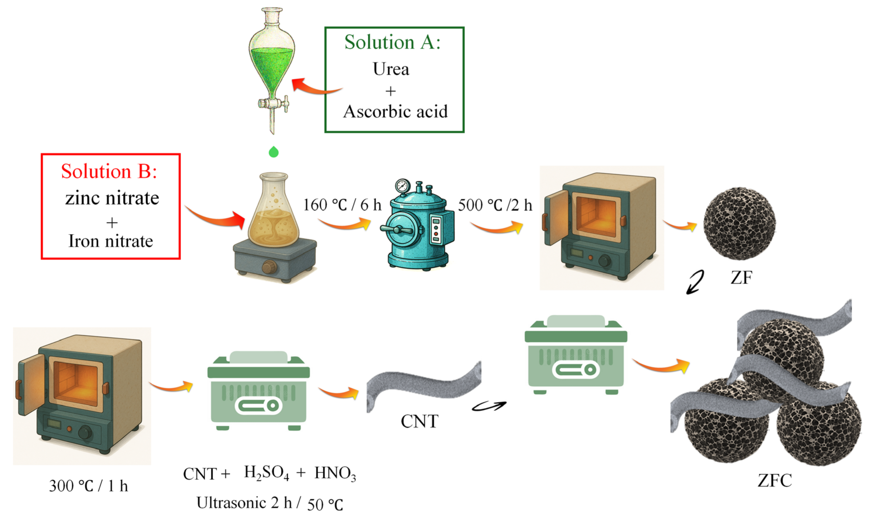
Figure 1. Schematic illustration of the synthesis process of ZF and the preparation of the ZFC composite.
Carbon 12 00051 g001
Figure 2. Schematic illustration of the fabrication process of the sensing layer on a cement-based pellet: (ac) preparation and coating steps, (d) assembled sensing element, and (e,f) optical images of the bare and coated cement pellet devices.
Carbon 12 00051 g002
Figure 3. Laboratory setup used for controlled gas exposure and electrical measurements.
Carbon 12 00051 g003
Figure 4. XRD patterns of pristine ZF and ZFC composite.
Carbon 12 00051 g004
Figure 5. FESEM images of (a,b) pristine ZF, (c) MWCNTs, and (df) ZFC composite at different magnifications; (g) TEM image and (h) HRTEM image of the ZFC sample.
Carbon 12 00051 g005
Figure 6. (a) EDS spectrum of the ZFC composite; (b) corresponding elemental mapping images of Zn, Fe, C, and O.
Carbon 12 00051 g006
Figure 7. (a) N2 adsorption–desorption isotherms; (b) pore size distribution curve of the ZFC composite.
Carbon 12 00051 g007
Figure 8. Dynamic H2 sensing response of the ZFC composite deposited on cement toward 10,000 ppm H2 under different operating temperatures (24–72 °C) and relative humidity levels (≈32–87% RH) during cyclic flow-through exposure (SD ≤ 7%): (a) 24 °C, RH ≈ 32%; (b) 24 °C, RH ≈ 56%; (c) 24 °C, RH ≈ 87%; (d) 39 °C, RH ≈ 32%; (e) 39 °C, RH ≈ 54%; (f) 39 °C, RH ≈ 86%; (g) 52 °C, RH ≈ 31%; (h) 52 °C, RH ≈ 58%; (i) 52 °C, RH ≈ 84%; (j) 72 °C, RH ≈ 33%; (k) 72 °C, RH ≈ 58%; and (l) 72 °C, RH ≈ 82%.
Carbon 12 00051 g008
Figure 9. XGBoost performance for H2 concentration prediction under dynamic ramp exposure. (a) Parity plot of predicted versus measured concentration showing close agreement with the 1:1 line up to 10,000 ppm. (b,c) Residuals as a function of prediction and their probability density, indicating small, nearly Gaussian, zero-centered errors. (d) Five-fold cross-validation boxplots of R2 and RMSE (median R2 ≈ 0.92, RMSE ≈ 820 ppm) confirming high and statistically consistent predictive accuracy.
Carbon 12 00051 g009
Table 1. tres of ZFC sensor toward 10,000 ppm H2 at different operating temperatures and relative humidity levels.
T(°C)24395272
RH%
3236 s22.5 s31.5 s40.5 s
5627 s18 s22.5 s34.2 s
8731.5 s22 s27 s36 s
Disclaimer/Publisher’s Note: The statements, opinions and data contained in all publications are solely those of the individual author(s) and contributor(s) and not of MDPI and/or the editor(s). MDPI and/or the editor(s) disclaim responsibility for any injury to people or property resulting from any ideas, methods, instructions or products referred to in the content.