Article

Conversion of Carbon Dioxide into Solar Fuels Using MgFe2O4 Thermochemical Redox Chemistry

Department of Chemical Engineering, University of Tennessee, 615 Mccallie Ave, Chattanooga, TN 37403, USA
Submission received: 27 December 2024 / Revised: 9 March 2025 / Accepted: 21 March 2025 / Published: 25 March 2025
(This article belongs to the Section CO2 Utilization and Conversion)

Abstract

:
Transforming H2O and CO2 into solar fuels like syngas is crucial for future sustainable transportation fuel production. Therefore, the MgFe2O4/CO2 splitting cycle was thermodynamically scrutinized to estimate its solar-to-fuel energy conversion efficiency in this investigation. The thermodynamic data required to solve the modeling equations were obtained using the HSC Chemistry program. The reduction non-stoichiometry was assumed to be equal to 0.1 for all computations. One of the study’s primary goals was to examine the impact of the inert sweep gas’s molar flow rate on the process parameters related to the MgFe2O4/CDS cycle. Overall, it was understood that the effect of the inert sweep gas’s molar flow rate on the thermal reduction temperature was significant when it increased from 10 to 40 mol/s compared to the rise from 40 to 100 mol/s. The energy needed to reduce MgFe2O4 increased slightly due to the surge in the inert sweep gas’s molar flow rate. In contrast, the energy penalty for heating MgFe2O4-δred from the re-oxidation to thermal reduction temperature significantly decreased. Including gas-to-gas heat exchangers with a gas-to-gas heat recovery effectiveness equal to 0.5 helped reduce the energy demand for heating the inert sweep gas. Overall, although the rise in the inert sweep gas’s molar flow rate from 10 to 100 mol/s caused a drop in the thermal reduction temperature by 180 K, the total solar energy needed to drive the cycle was increased by 85.7 kW. Accordingly, the maximum solar-to-fuel energy conversion efficiency (13.1%) was recorded at an inert sweep gas molar flow rate of 10 mol/s, which decreased by 3.7% when it was increased to 100 mol/s.

Graphical Abstract

1. Introduction

Solar-driven thermochemical valorization of CO2 into fuels and chemicals is a promising solution to CO2-driven climate change [1,2,3]. A metal oxide (MO)-based two-step thermochemical cycle can be accomplished by converting CO2 into CO via the CO2 splitting (CDS) reaction, which can then be combined with H2 produced from H2O via a water splitting (WS) reaction to make syngas [4,5,6]. The solar syngas can be converted into liquid transportation fuels like kerosene, diesel, and petrol by adjusting the H2-to-CO ratio and using a catalytic Fischer Tropsch process [7,8]. A critical focus of the solar thermochemical community is recognizing the best MO candidate to convert CO2 and H2O into solar fuels. To date, many volatile and non-volatile MOs have been investigated theoretically and experimentally. ZnO/Zn [9,10,11,12,13] and SnO2/SnO/Sn [12,14,15,16] are the two main volatile MO pairs that have been scrutinized for use in the solar thermochemical WS and CDS cycle. On the other hand, a variety of non-volatile MOs belonging to the doped iron oxide (ferrites) [17,18,19,20,21,22,23], ceria and doped ceria [24,25,26,27,28,29,30,31,32], and perovskite oxide [33,34,35,36,37,38,39,40] families have been inspected.
In particular, in the case of doped iron oxides (ferrites), various combinations, including Zn-ferrite, Ni-ferrite, and Co-ferrite, have been examined for both WS and CDS. Promising outcomes for solar thermochemical fuel synthesis via WS and CDS were demonstrated by Zn-ferrite produced using an aerosol spray method [41] and a sol–gel approach aided by propylene oxide [42]. For solar H2 production, commercially available Zn-ferrite was evaluated despite the notable performance of synthesized Zn-ferrites [43]. According to a thermodynamic efficiency investigation, the Ni-ferrite-based WS cycle obtained a remarkable 35.5% efficiency [44]. To achieve this, the thermal reduction and WS temperatures were held at 1600 K and 1000 K, respectively, while the O2 partial pressure was kept constant at 10−5 bar. By adding ZrO2, polyethylene glycol, and carbon black to the solid-state synthesis method, Teknetzi et al. [45] were able to increase the porosity and thermal stability of Ni-ferrite, which in turn increased its redox reactivity while splitting H2O and CO2. When Goikoetxea et al. [46] examined Ni-ferrite and Co-ferrite powders in thermochemical WS reactions, they found that Co-ferrite generated more H2 than Ni-ferrite. Takalkar et al. [47,48] reported a similar outcome for Ni-ferrite and Co-ferrite in thermochemical CDS reactions.
Besides Zn-ferrite, Ni-ferrite, and Co-ferrite, the solar thermochemical community has recently invested in exploring the utility of Mg-ferrite for WS and CDS applications. Randhir et al. [49] scrutinized the redox processes linked to Mg-ferrite and MgO that induce the formation of H2 via WS and reported a better performance for Mg-ferrite compared to ceria in terms of the amount of H2 produced and the temperatures required for the cycle operation. Takalkar and Bhosale [50] synthesized various combinations of MgxFe3−xO4 (x = 0.2 to 1) using the sol–gel method for CDS. They reported that MgFe2O4 produced the highest amount of CO compared to the other investigated Mg-ferrite structures.
It is essential to estimate the efficiency of a MO-driven WS/CDS cycle in converting solar energy into fuel. Although experimental results have shown that MgFe2O4 has the potential to produce H2 and CO, a thorough efficiency analysis of the MgFe2O4-driven WS/CDS cycle has not been reported. Therefore, in this investigation, a detailed efficiency analysis of the MgFe2O4/CDS cycle was performed by following the redox chemistry presented in Equations (1) and (2). The prime objective of this study was to explore the influence of the molar flow rate of Ar ( n ˙ i n e r t ) on the energy penalty associated with the (a) TR of MgFe2O4, (b) heating of MgFe2O4-δred from the reoxidation temperature ( T o x d ) to the reduction temperature ( T r e d ), (c) separation of Ar from O2 and CO from unreacted CO2, (d) preheating of the Ar, and others. Ultimately, the operating conditions suitable for achieving the maximum solar-to-fuel energy conversion efficiency ( η s o l a r t o f u e l ) were identified.
M g F e 2 O 4 M g F e 2 O 4 δ r e d + δ r e d 2 O 2
M g F e 2 O 4 δ r e d + ( δ r e d ) C O 2 M g F e 2 O 4 + ( δ r e d ) C O
Solar thermochemical H2O/CO2 splitting cycles involve two steps, with the thermal reduction step being endothermic and requiring elevated temperatures to yield a significant amount of O2. To lower the temperature and minimize the energy demand for this thermal reduction, an inert gas environment is introduced into the thermochemical process. By employing inert sweep gases like argon, the thermodynamic equilibrium can be adjusted to enable lower operating temperatures. However, using excessive amounts of the inert sweep gas results in extra heat energy being consumed to heat it, which ultimately leads to an increased demand for solar energy and a decrease in the solar-to-fuel energy conversion efficiency. For these reasons, it is crucial to investigate the impact of inert sweep gas flow rates on the thermodynamic efficiency of the MgFe2O4/CDS cycle.

2. Thermodynamic Model

A detailed thermodynamic model was developed (presented in Figure 1) and utilized to estimate η s o l a r t o f u e l and other process parameters associated with the MgFe2O4/CDS cycle. The assumptions employed for performing the analysis are listed in Table 1. Separate reaction chambers were incorporated into the process model, one for the reduction of MgFe2O4 into MgFe2O4-δred (Equation (1)) and the other for the re-oxidation of the reduced MgFe2O4-δ into MgFe2O4 via the CDS reaction (Equation (2)). The reduction of MgFe2O4 resulted in the release of O2 due to the TR reaction. In contrast, the re-oxidation of MgFe2O4-δred resulted in the production of CO via CDS. The reduction chamber was operated at T r e d , whereas the oxidation chamber was operated at T o x d . The reduction non-stoichiometry ( δ r e d ) related to the TR of MgFe2O4 was assumed to be 0.1 for the entire thermodynamic efficiency analysis.
Since it is considered more inert than nitrogen (N2) and has been used in experimental investigations of MO-driven CDS processes [33,51], argon (Ar) was employed as the inert sweeping gas to lower the O2 partial pressure in the reduction chamber in order to achieve the expected TR of MgFe2O4 at a lower T r e d . As shown in Figure 1, states r e d 1 and r e d 2 were the entering and exit points for the Ar. The MgFe2O4 was fed into the reduction chamber at state r e d 3 , and the thermally reduced MgFe2O4-δred was transported out from it at state r e d 4 . The countercurrent flow of the ferrite and the Ar in the reduction chamber is ensured by this configuration. The energy needed to drive the TR of MgFe2O4 was estimated using the following equation:
Q ˙ M g F r e d = n ˙ M g F H M g F e 2 O 4 M g F e 2 O 4 δ r e d + δ r e d 2 O 2
Likewise, the energy penalty from heating MgFe2O4-δred from T o x d to T r e d was computed according to Equation (4).
Q ˙ M g F s e n s = n ˙ M g F H M g F e 2 O 4 δ r e d @ T o x d M g F e 2 O 4 δ r e d @ T r e d
In Equations (3) and (4), as well as in the equations reported in the next paragraphs, n ˙ M g F was assumed to equal 1 mol/s.
The O2 generated via the TR of MgFe2O4 was moved out of the reduction chamber with the help of the Ar. To lower the temperature of the gas combination of O2 and Ar from T r e d to T s e p 1 , HEX-2 was installed. After passing through HEX-2 and achieving the desired temperature ( T s e p 1 ), the gas mixture was processed through separator-1. As explained in prior publications [34,52,53], the O2 was separated from the Ar in separator-1, and the energy required for this separation can be estimated as follows:
Q ˙ s e p 1 = n ˙ M g F T s e p 1 η s e p 1 ( Δ S m i x , r e d 2 Δ S m i x , r e d 1 )
Δ S m i x , r e d 1 = R n i n e r t l n ( 1 y O 2 , r e d 1 ) + n O 2 , r e d 1 l n y O 2 , r e d 1
Δ S m i x , r e d 2 = R n i n e r t l n ( 1 y O 2 , r e d 2 ) + n O 2 , r e d 2 l n y O 2 , r e d 2
After attaining the desired level of separation, the O2 exited separator-1 and was transferred to HEX-3. In HEX-3, the O2 was cooled from T s e p 1 to T 0 = 298 K and then moved on to the CO/O2 fuel cell. Instead, the Ar that came out of separator-1 was passed through HEX-2 and HEX-3, and a supplementary heater-1. The following energy balance equations were used to estimate the heat energy required to warm the Ar from T s e p 1 to T r e d :
Q ˙ i n e r t h e a t = ε g g Q ˙ i n e r t + O 2 c o o l + Q ˙ O 2 c o o l + Q ˙ h e a t e r 1
where
Q ˙ i n e r t h e a t = n ˙ i n e r t H i n e r t @ T s e p 1 i n e r t @ T r e d
Q ˙ i n e r t + O 2 c o o l = n ˙ i n e r t H i n e r t @ T r e d i n e r t @ T s e p 1 + n ˙ O 2 H O 2 @ T r e d O 2 @ T s e p 1
Q ˙ O 2 c o o l = n ˙ O 2 H O 2 @ T s e p 1 O 2 @ T 0
To completely re-oxidize MgFe2O4-δred into MgFe2O4 via CDS, an excess amount of CO2 (10 δ r e d ) was used. CO2 goes into the oxidation chamber at state o x d 3 . After concluding the re-oxidation step, the unreacted CO2 left the oxidation chamber at state o x d 4 as a mixture with the CO produced via CDS. MgFe2O4-δred produced via the TR of MgFe2O4 in the reduction chamber was first cooled from T r e d to T o x d by passing through HEX-1 and then it entered the oxidation chamber at o x d 1 . After the completion of the CDS reaction, the re-oxidized MgFe2O4 exited the oxidation chamber at state o x d 3 . Before entering the reduction chamber, MgFe2O4 passed through HEX-1 to be preheated from T o x d to T r e d . Despite the inclusion of HEX-1 in the model, it was assumed that the solid-to-solid heat recovery efficacy ( ε s s ) was zero.
The following formula was used to determine the thermal energy released from the oxidation chamber because CDS is an exothermic reaction:
Q ˙ M g F o x d = n ˙ M g F H M g F e 2 O 4 δ r e d + ( 10 δ r e d ) C O 2 M g F e 2 O 4 + ( 9 δ r e d ) C O 2 + ( δ r e d ) C O
Even though the Ar can be preheated using the exothermic heat generated during the CDS process, due to the challenges associated with recuperating this heat energy, in this investigation, we have assumed that Q ˙ M g F o x d was discharged to the surroundings.
The CO2 was preheated from T 0 to T o x d before entering the oxidation chamber, which was set at T o x d . The preheating of the CO2 was achieved by using HEX-4 and a supplemental heater-2. The calculations for the energy required to preheat the CO2 were conducted as follows:
Q ˙ C O 2 h e a t = ε g g Q ˙ C O 2 + C O c o o l + Q ˙ h e a t e r 2
where
Q ˙ C O 2 h e a t = n ˙ C O 2 H C O 2 @ T 0 C O 2 @ T o x d
Q ˙ C O 2 + C O c o o l = n ˙ C O 2 H C O 2 @ T o x d C O 2 @ T s e p 2 + n ˙ C O H C O @ T o x d C O @ T s e p 2
Separator-2 was set up in the process to separate the unreacted CO2 from the CO generated. The separation of CO2 from the CO is feasible at 298 K with the help of a membrane-based separation technique [54]. With the aid of HEX-4, the gas mixture consisting of CO2 and CO was first cooled from T o x d to T s e p 2 before being sent to the separator-2, which was operating at T s e p 2 = 298 K. Equations (16)–(18) were used to evaluate the thermal energy penalty associated with separator-2 operation.
Q ˙ s e p 2 = n ˙ M g F T s e p 2 η s e p 2 ( Δ S m i x , o x d 4 Δ S m i x , o x d 3 )
Δ S m i x , o x d 3 = R n C O 2 l n ( 1 y C O , o x d 3 ) + n C O , o x d 3 l n y C O , o x d 3
Δ S m i x , o x d 4 = R n C O 2 l n ( 1 y C O , o x d 4 ) + n C O , o x d 4 l n y C O , o x d 4
The CO/O2 fuel cell, which operated at 100% efficiency, received the CO that had been separated from the CO2. After the CO and O2 in the fuel cell interact, the CO2 was recombined with the CO2 exiting separator-2. In order to re-oxidize MgFe2O4-δred, the combined stream of CO2 was warmed from T 0 to T o x d by passing it through HEX-4 and heater-2. It was then recycled to the oxidation chamber.
The thermal energy required to run the MgFe2O4/CDS cycle was estimated using Equation (19):
Q ˙ T C = Q ˙ M g F r e d + Q ˙ M g F s e n s + Q ˙ h e a t e r 1 + Q ˙ h e a t e r 2 + Q ˙ s e p 1 + Q ˙ s e p 2 + Q ˙ s u r f
Twenty percent of the thermal energy used to propel the TR of MgFe2O4 was thought to be lost through conductive and convective heat losses from the reduction chamber’s surface:
Q ˙ s u r f = 0.2 × Q ˙ M g F r e d
Using Q ˙ T C , the total solar energy needed to operate the MgFe2O4/CDS cycle was determined using the following equation:
Q ˙ s o l a r = Q ˙ T C η a b s o r p t i o n
The solar energy absorption efficiency and the re-radiation losses from the MgFe2O4/CDS cycle were estimated as per the equations listed below:
η a b s o r p t i o n = 1 σ T r e d 4 I C
Q ˙ r e r a d = ( 1 η a b s o r p t i o n ) × Q ˙ s o l a r
where
σ = 5.6705 × 10⁻⁸ W/m2·K4, I = 1000 W/m2, and C = 3000 suns
Finally, η s o l a r t o f u e l of the MgFe2O4/CDS cycle was calculated as follows:
η s o l a r t o f u e l = n ˙ C O × H H V C O Q ˙ s o l a r

3. Results and Discussion

The influence of n ˙ i n e r t on T r e d , which is required to thermally convert the MgFe2O4 into MgFe2O4-δred ( δ r e d = 0.1), was examined as a preliminary step in the thermodynamic efficiency analysis. According to the findings in Figure 2, T r e d was significantly impacted by an increase in n ˙ i n e r t . T r e d dropped from 1445 K to 1390 K when n ˙ i n e r t was raised from 10 mol/s to 20 mol/s. Similarly, T r e d decreased from 1390 K to 1355 K when n ˙ i n e r t increased from 20 mol/s to 30 mol/s. It was understood that the influence of n ˙ i n e r t on T r e d was sizable when n ˙ i n e r t increased from 10 to 40 mol/s compared to the upturn in n ˙ i n e r t from 40 to 100 mol/s. This increase in n ˙ i n e r t aided in reducing T r e d by 115 K. In contrast, the surge in n ˙ i n e r t from 40 to 100 mol/s only decreased T r e d by 65 K. Overall, the maximum (1445 K) and minimum (1265 K) T r e d were recorded for an n ˙ i n e r t equal to 10 and 100 mol/s, respectively.
After understanding the relationship between n ˙ i n e r t and T r e d , the Q ˙ M g F r e d needed to thermally reduce MgFe2O4 into MgFe2O4-δred ( δ r e d = 0.1) was estimated using Equation (3). The energy required to preheat Ar from T s e p 1 to T r e d and MgFe2O4 from T o x d to T r e d was not taken into account in the Q ˙ M g F r e d calculation because the reduction chamber only deals with the reduction of MgFe2O4. As reported in Figure 3, even though T r e d was reduced by 180 K due to the rise in n ˙ i n e r t from 10 to 100 mol/s, Q ˙ M g F r e d increased by 0.5 kW. The higher decrease in the enthalpy of the reactant MgFe2O4 (33.1 kJ/mol) compared to the cumulative fall in the enthalpy of the products, i.e., MgFe2O4-δred and O2 (32.6 kJ/mol), when T r e d was reduced from 1445 K to 1265 K was attributed to the rise in Q ˙ M g F r e d . Interestingly, Q ˙ M g F r e d increased from 32.6 kW to 33.0 kW when n ˙ i n e r t surged from 10 to 40 mol/s. However, when n ˙ i n e r t increased from 40 to 60 mol/s and from 70 to 100 mol/s, Q ˙ M g F r e d remained steady at 33.0 kW and 33.1 kW, respectively.
Equation (4) was employed to estimate the Q ˙ M g F s e n s required for preheating MgFe2O4 from T o x d to T r e d . Despite the installation of HEX-1, the ε s s was taken to be zero because of the difficulties in recovering energy from the solids. The assumption of ε s s = 0 confirmed that the thermal energy dissipated due to the cooling of MgFe2O4-δred from T r e d to T o x d was not re-utilized for the preheating of MgFe2O4 from T o x d to T r e d . Even though the drop in T r e d due to the rise in n ˙ i n e r t did not affect Q ˙ M g F r e d much, Q ˙ M g F s e n s decreased considerably (Figure 3). An increase in n ˙ i n e r t from 10 to 20 mol/s decreased Q ˙ M g F s e n s from 84.8 to 74.5 kW. A further increase in n ˙ i n e r t up to 30, 40, and 50 mol/s resulted in a drop in Q ˙ M g F s e n s to 68.0, 63.4, and 61.6 kW, respectively. Although the decrease in Q ˙ M g F s e n s continued as n ˙ i n e r t increased from 50 to 100 mol/s, the data presented in Figure 3 confirmed that this drop was lower compared to the reduction in Q ˙ M g F s e n s when n ˙ i n e r t surged from 10 to 50 mol/s. When n ˙ i n e r t increased from 10 to 50 mol/s, the decrease in Q ˙ M g F s e n s was 13.3 kW more than the drop that occurred when n ˙ i n e r t increased from 50 to 100 mol/s.
The MgFe2O4-δred was moved to the oxidation chamber following the heat reduction stage. The temperature of the MgFe2O4-δred was lowered from T r e d to T o x d before entering the oxidation chamber. Simultaneously, excess CO2 (10 δ r e d ) also entered the oxidation chamber at T o x d . As the influence of T o x d on the efficiency of the MgFe2O4/CDS cycle was not the focus of the investigation, all the thermodynamic estimations were carried out at steady T o x d = 1000 K. Because of the unchanged reaction stoichiometry and T o x d , as shown in Figure 3, Q ˙ M g F o x d remained steady at 5.7 kW, irrespective of the variations in n ˙ i n e r t and T r e d .
Once the reduction of MgFe2O4 was over, Ar transported the generated O2 out of the reduction chamber. Separating the two gases was essential as the Ar was needed in the reduction chamber to assist with the TR of MgFe2O4. Likewise, O2 was necessary to operate the CO/O2 fuel cell. Ar and O2 were separated using Ion Transport Membrane (ITM) technology that is capable of separating gases at temperatures from 1050 to 1200 K [55,56]. ITM technology can efficiently extract pure O2 from a gas mixture using ceramic membranes that selectively allow O2 ions to pass through. Unlike traditional air separation methods such as cryogenic distillation, ITM can achieve extremely high levels of O2 purity. Additionally, this technology operates at higher temperatures, aligning perfectly with the requirements of the solar thermochemical process. In this investigation, the Ar and O2 separation was carried out at T s e p 1 = 1123 K. Thus, using HEX-2 ( ε g g = 0.5), the gas mixture consisting of Ar and O2 was further cooled from T r e d to T s e p 1 .
Equations (5)–(7) were utilized to determine the Q ˙ s e p 1 needed to separate Ar and O2. The equations for calculating Q ˙ s e p 1 were established based on the second law of thermodynamics Δ Q = T Δ S . Furthermore, the estimation of Q ˙ s e p 1 under different operating conditions was achieved by determining the entropy of gas mixing. Q ˙ s e p 1 was determined by assuming a separator efficiency equal to 15% and an extent of separation of O2 and the Ar equal to 99.9%. Due to the increase in n ˙ i n e r t , the deviations in y O 2 , r e d 1 and y O 2 , r e d 2 at states r e d 1 and r e d 2 in the reduction chamber were recorded. As y O 2 , r e d 1 and y O 2 , r e d 2 decreased by 4.5 × 10⁻⁶ and 4.5 × 10⁻³ due to the rise in n ˙ i n e r t from 10 to 100 mol/s, Δ S m i x , r e d 1 and Δ S m i x , r e d 2 increased by 9.6 × 10⁻⁴ (J/mol·K) and 0.96 (J/mol·K), respectively. This increase in S m i x , r e d 1 , and Δ S m i x , r e d 2 led to a rise in Q ˙ s e p 1 from 19.6 kW to 26.7 kW when n ˙ i n e r t increased from 10 to 100 mol/s (Figure 4).
Separator-1 had two exit streams for O2 and Ar. O2 was relocated to the fuel cell via HEX-3 ( ε g g = 0.5), through which, its temperature was decreased from T s e p 1 to T o (298 K). After exiting separator-1, Ar was preheated from T s e p 1 to T r e d via HEX-2 and HEX-3 (each with an ε g g = 0.5) and an auxiliary heater-1 before entering the reduction chamber. Q ˙ i n e r t h e a t was calculated using Equation (9) and reported in Table 2. The results showed that even though the rise in n ˙ i n e r t reduced T r e d , Q ˙ i n e r t h e a t was increased. As n ˙ i n e r t increased from 10 mol/s to 20, 40, 60, 80, and 100 mol/s, Q ˙ i n e r t h e a t increased above 66.9 kW by 44.1, 105.2, 160.1, 194.2, and 228.3 kW, respectively. n ˙ i n e r t had a more significant impact on Q ˙ i n e r t h e a t than the drop in T r e d .
As seen in Figure 1, the Ar was initially transferred through HEX-2, where the energy penalty associated with heating the Ar from T s e p 1 to T r e d was satisfied by using the energy released during the cooling of the Ar + O2 gas combination from T r e d to T s e p 1 . Passing through HEX-2 helped lower the Q ˙ i n e r t h e a t , as shown by the data in Figure 5. For example, for n ˙ i n e r t = 10, 40, 70, and 100 mol/s, Q ˙ i n e r t h e a t decreased by 33.8, 86.2, 121.7, and 147.7 kW, respectively. Ar was permitted to flow through HEX-3 after leaving HEX-2, where Q ˙ O 2 c o o l was used to preheat the Ar. Passing through HEX-3 reduced Q ˙ i n e r t h e a t slightly as the Q ˙ O 2 c o o l available for re-utilization was very small. For example, for n ˙ i n e r t = 10, 40, 70, and 100 mol/s, Q ˙ i n e r t h e a t decreased by 0.68, 0.68, 0.97, and 0.93 kW, respectively, after passing through HEX-3. By adding an auxiliary heater-1 to the cycle, the energy penalty for preheating the Ar after it had passed through both heat exchangers was satisfied. Table 2 shows the expected Q ˙ h e a t e r 1 for preheating Ar from T s e p 1 to T r e d . Increasing n ˙ i n e r t from 10 to 100 mol/s resulted in a 4.5-fold increase in Q ˙ h e a t e r 1 .
In a typical CDS experiment, excess CO2 is continuously fed to the thermochemical reactor [57,58,59]. As we attempted to perform the thermodynamic efficiency analysis by taking into account the most realistic operating conditions, we assumed that a surplus amount of CO2 was fed to the oxidation chamber (10 times δ r e d ) to re-oxidize the MgFe2O4-δred into MgFe2O4 via CDS. As an excess amount of CO2 (10 δ r e d ) was used during the CDS reaction, due to the reaction chemistry associated with the re-oxidation of MgFe2O4-δred, a CO2 amount of 9 δ r e d remained unreacted after attaining 100% re-oxidation of MgFe2O4-δred.
After the CDS reaction was finished, a gas mixture comprising unreacted CO2 and CO generated during CDS exited the oxidation chamber at T o x d . Since separator-2 was running at T s e p 2 = 298 K, the CO/CO2 gas mixture was cooled from T o x d to T s e p 2 using HEX-4 ( ε g g = 0.5) and it subsequently went into separator-2, which separated 99.9% of the CO from the CO2. The Q ˙ s e p 2 needed to achieve this separation was estimated using Equations (16)–(18). Notably the re-oxidation chemistry of the MgFe2O4/CDS cycle was unchanged over the entire investigation period (at all n ˙ i n e r t values). In addition, as n ˙ C O 2 and n ˙ C O passed through the process, the y C O , o x d 3 and y C O , o x d 4 at the entrance (state o x d 3 ) and exit (state o x d 4 ) of the oxidation chamber remained unchanged even though n ˙ i n e r t varied from 10 to 100 mol/s. Therefore, the Q ˙ s e p 2 required for the 99.9% separation of CO from CO2 stayed fixed at 5.4 kW regardless of the variation in n ˙ i n e r t and T r e d .
Following separation from CO2, the CO was reacted with O2 in the CO/O2 fuel cell at 298 K. The resulting CO2 was then combined with the unreacted CO2, which came out of separator-2 at the same temperature. After passing through HEX-4 and heater-2, the combined stream of CO2 was heated to T o x d . It was then recycled to the oxidation chamber to carry out the CDS process, which re-oxidized MgFe2O4-δred. As the T o x d and T o remained steady at 1000 and 298 K, respectively, Q ˙ C O 2 h e a t was constant at 33.4 kW, irrespective of the rise in n ˙ i n e r t . However, as 50% of Q ˙ C O 2 + C O c o o l was re-utilized for preheating the CO2 in HEX-4, the supplemental Q ˙ h e a t e r 2 was equal to 17.3 kW.
The published literature on the experimental evaluation of MO-driven CDS using thermochemical reactors [60,61,62] used appropriate insulating materials to avoid conductive and convective losses from the heated surfaces. However, complete elimination of the heat losses was never achieved. Therefore, we estimated 20% heat losses from the solar reactor’s surface in our calculations to be more realistic when assessing the process’s efficiency. By employing Equation (20), Q ˙ s u r f was calculated, and its variation with the rise in n ˙ i n e r t is presented in Figure 6. As Q ˙ s u r f was dependent on Q ˙ M g F r e d , due to the rise in n ˙ i n e r t from 10 to 100 mol/s, it increased by 1.5%. Figure 6 further shows that the slope of increase in Q ˙ s u r f was steeper when n ˙ i n e r t surged from 10 to 40 mol/s than when it decreased from 40 to 60 mol/s.
After discovering the influence of n ˙ i n e r t on individual process parameters for the MgFe2O4/CDS cycle, the Q ˙ T C needed to operate the cycle was calculated using Equation (19). In Equation (19), Q ˙ T C is a summation of the energy penalties of the individual process components of the MgFe2O4/CDS cycle. The variation in Q ˙ T C due to the increase in n ˙ i n e r t from 10 to 100 mol/s is illustrated in Figure 7. Due to the rise in n ˙ i n e r t , except for Q ˙ M g F s e n s , all the other process parameters such as Q ˙ M g F r e d , Q ˙ h e a t e r 1 , Q ˙ s e p 1 , etc., increased, which resulted in a surge in Q ˙ T C . The data presented in Figure 7 show that at n ˙ i n e r t = 10 mol/s, most of the Q ˙ T C encompassed Q ˙ M g F s e n s . However, as n ˙ i n e r t increased from 10 to 100 mol/s, Q ˙ M g F s e n s was reduced, whereas Q ˙ h e a t e r 1 increased. It is evident from the presented data that the influence of Q ˙ h e a t e r 1 on Q ˙ T C was higher than that of Q ˙ M g F s e n s , especially at higher n ˙ i n e r t values. Besides the increase in Q ˙ s e p 1 , the increase in n ˙ i n e r t also resulted in a higher Q ˙ T C . Overall, Q ˙ T C increased from 198.7 to 287.6 kW when n ˙ i n e r t surged from 10 to 100 mol/s.
To estimate the Q ˙ s o l a r needed for the MgFe2O4/CDS cycle, besides Q ˙ T C , the estimation of η a b s o r p t i o n and Q ˙ r e r a d is essential. Equation (22) was employed to determine η a b s o r p t i o n and the results reported in Table 3 confirm that η a b s o r p t i o n increased due to the surge in n ˙ i n e r t as T r e d decreased. For example, as n ˙ i n e r t increased from 10 to 40, 70, and 100 mol/s, T r e d decreased from 1445 to 1330, 1290, and 1265 K, respectively, and consequently, η a b s o r p t i o n increased from 91.8% to 94.1%, 94.8%, and 95.2%. On the other hand, Q ˙ r e r a d , calculated using Equation (23), was highest (17.8 kW) for n ˙ i n e r t = 10 mol/s and then varied in the range of 14.4 kW to 15.2 kW when n ˙ i n e r t varied from 30 to 100 mol/s.
Q ˙ s o l a r and η s o l a r t o f u e l were computed individually using Equations (21) and (24). According to Equation (21), Q ˙ s o l a r is directly proportional to Q ˙ T C and inversely proportional to η a b s o r p t i o n . Therefore, as Q ˙ T C increased and η a b s o r p t i o n decreased, Q ˙ s o l a r increased. As shown in Figure 8, the lowest Q ˙ s o l a r (216.5 kW) was recorded at n ˙ i n e r t = 10 mol/s, and it increased to 302.3 kW as n ˙ i n e r t surged to 100 mol/s. The rise in Q ˙ s o l a r for every 10 mol/s increase in n ˙ i n e r t from 10 to 100 mol/s is reported in Figure 9. The results confirmed that with each 10 mol/s increase in n ˙ i n e r t , Q ˙ s o l a r rose but the amount that it rose was not consistent. For example, when n ˙ i n e r t increased from 10 to 20 mol/s, Q ˙ s o l a r increased by 12.4 kW. However, when n ˙ i n e r t increased from 20 mol/s to 30 mol/s, the increase in Q ˙ s o l a r was only 4.2 kW. The maximum surge in Q ˙ s o l a r (16.3 kW) was recorded when n ˙ i n e r t increased from 30 mol/s to 40 mol/s.
By utilizing the estimated amounts of Q ˙ s o l a r , η s o l a r t o f u e l was determined as a function of the rise in n ˙ i n e r t by using Equation (24). The numerator of Equation (24) includes multiplying n ˙ C O (steady at 0.1) and H H V C O (283.24 kW). On the other hand, the denominator is Q ˙ s o l a r , which varies with increases in n ˙ i n e r t . As the numerator value was fixed at 28.3 kW, the estimation of η s o l a r t o f u e l was entirely dependent on Q ˙ s o l a r . As shown in Figure 8, Q ˙ s o l a r increased with n ˙ i n e r t . Therefore, as shown in Figure 10, η s o l a r t o f u e l decreased when n ˙ i n e r t increased. For example, the increase in n ˙ i n e r t from 10 to 40, 70, and 100 mol/s resulted in a decrease in η s o l a r t o f u e l to 11.4%, 10.1%, and 9.4%, respectively. The slope of the decrease in η s o l a r t o f u e l was steeper when n ˙ i n e r t increased from 30 to 60 mol/s compared when n ˙ i n e r t increased from 10 to 30 mol/s and 60 to 100 mol/s, respectively. The highest η s o l a r t o f u e l (13.1%) was recorded when n ˙ i n e r t was equal to 10 mol/s.

4. Summary and Conclusions

The impact of the increase in the molar flow rate of the inert gas on MgFe2O4/CDS cycle process parameters was examined in this study. The reduction temperature needed for reducing MgFe2O4 into MgFe2O4-δred ( δ r e d = 0.1) decreased from 1445 to 1265 K when the molar flow rate of the inert gas increased from 10 to 100 mol/s. The influence of the increase in the molar flow rate of the inert gas on the energy required for the thermal reduction of MgFe2O4 (surged by 0.5 kW) was minor and but on the energy needed to heat the MgFe2O4-δred (reduced by 33.1 kW), the effect was significant. Because of the surge in the molar flow rate of the inert gas, the entropy of the gases to be separated increased, resulting in an increase in the energy required to operate separator-1 of 7.2 kW. Due to the employment of HEX-1 ( ε g g = 0.5), even though the energy required for heating the inert gas was diminished by 50%, a significant amount of energy was still needed, which was supplied by auxiliary heater-1. The energy required for heater-1 increased by 114.3 kW with an increase in the molar flow rate of the inert gas from 10 to 100 mol/s. On the other hand, the energy required for heater-2 remained steady at 17.3 kW. As the increase in energy required for heater-1 (114.3 kW) was considerably higher than the drop in energy needed to heat the MgFe2O4-δred (33.1 kW), the total thermochemical energy necessary to drive the cycle increased by 88.9 kW as the molar flow rate of the inert gas increased from 10 to 100 mol/s. This surge in the total thermochemical energy required to drive the cycle was responsible for the rise in the total solar energy needed to operate the cycle, from 216.5 kW up to 302.3 kW. Consequently, the solar-to-fuel energy conversion efficiency was highest (13.1%) and lowest (9.4%) at inert gas molar flow rates of 10 mol/s and 100 mol/s, respectively.

Funding

This research received no external funding.

Data Availability Statement

The original contributions presented in this study are included in the article. Further inquiries can be directed to the corresponding author.

Acknowledgments

Rahul R. Bhosale gratefully acknowledges the support provided by the University of Tennessee at Chattanooga.

Conflicts of Interest

The author declares no conflicts of interest.

Nomenclature

CSolar flux concentration ratio, suns
H H V C O Higher heating value of CO, kW
HEX-1Solid-to-solid heat exchanger 1
HEX-2Gas-to-gas heat exchanger 2
HEX-3Gas-to-gas heat exchanger 3
HEX-4Gas-to-gas heat exchanger 4
INormal beam solar insolation, W/m2
MOMetal oxide
n Molar amount, mol
n C O , o x d 3 Molar   amount   of   CO   at   state   o x d 3 , mol
n C O , o x d 4 Molar   amount   of   CO   at   state   o x d 4 , mol
n O 2 , r e d 1 Molar   amount   of   O 2   at   state   r e d 1 , mol
n O 2 , r e d 2 Molar   amount   of   O 2   at   state   r e d 2 , mol
n ˙ Molar flow rate, mol/s
n ˙ i n e r t Molar flow rate of inert, mol/s
n ˙ Z n F Molar   flow   rate   of   Z n F e 2 O 4 , mol/s
n ˙ C O 2 Molar flow rate of CO2, mol/s
n ˙ C O Molar flow rate of CO, mol/s
n ˙ O 2 Molar flow rate of O2, mol/s
Q ˙ i n e r t h e a t Thermal energy required to heat Ar, kW
Q ˙ i n e r t + O 2 c o o l Thermal energy released during cooling of inert + O2 gas mixture, kW
Q ˙ C O 2 + C O c o o l Thermal energy released during cooling of CO2 + CO gas mixture, kW
Q ˙ C O 2 h e a t Thermal energy required to heat CO2, kW
Q ˙ h e a t e r 1 Auxiliary thermal energy required to heat Ar, kW
Q ˙ h e a t e r 2 Auxiliary thermal energy required to heat CO2, kW
Q ˙ O 2 c o o l Thermal energy released during cooling of O2, kW
Q ˙ s o l a r Solar energy required to run the cycle, kW
Q ˙ s e p 1 Thermal energy required for the operation of separator-1, kW
Q ˙ s e p 2 Thermal energy required for the operation of separator-2, kW
Q ˙ s u r f Thermal energy losses over the reduction chamber walls, kW
Q ˙ T C Thermal energy required to run the cycle, Kw
Q ˙ M g F r e d Thermal energy required for thermal reduction of MgFe2O4, kW
Q ˙ M g F s e n s Thermal energy required to heat the MgFe2O4-δred, kW
Q ˙ M g F o x d Thermal energy released during re-oxidation of MgFe2O4-δred, kW
Q ˙ r e r a d Re-radiation losses from the cycle, kW
R Ideal gas constant (8.314 J/mol·K)
T 0 Ambient temperature, K
T o x d Oxidation (splitting) temperature, K
T r e d Reduction temperature, K
T s e p 1 Operating temperature of separator-1, K
T s e p 2 Operating temperature of separator-2, K
y C O , o x d 3 Mol   fraction   of   CO   at   state   o x d 3 , mol
y C O , o x d 4 Mol   fraction   of   CO   at   state   o x d 4 , mol
y O 2 , r e d 1 Mol   fraction   of   O 2   at   state   r e d 1 , mol
y O 2 , r e d 2 Mol   fraction   of   O 2   at   state   r e d 2 , mol
η a b s o p r t i o n Solar energy absorption efficiency, %
η s e p 1 Efficiency of separator-1, %
η s e p 2 Efficiency of separator-2, %
η s o l a r t o f u e l Solar-to-fuel energy conversion efficiency, %
δ r e d Reduction non-stoichiometry
ε g g Gas-to-gas heat recovery effectiveness
ε s s Solid-to-solid heat recovery effectiveness
σ Stefan–Boltzmann constant (5.670 × 10⁻⁸ W/m2·K4)

References

  1. Carrillo, R.J.; Scheffe, J.R. Advances and trends in redox materials for solar thermochemical fuel production. Solar Energy 2017, 156, 3–20. [Google Scholar] [CrossRef]
  2. Vaidya, P.D.; Kenig, E.Y. CO2-alkanolamine reaction kinetics: A review of recent studies. Chem. Eng. Technol. 2007, 30, 1467–1474. [Google Scholar] [CrossRef]
  3. Schäppi, R.; Rutz, D.; Dähler, F.; Muroyama, A.; Haueter, P.; Lilliestam, J.; Patt, A.; Furler, P.; Steinfeld, A. Drop-in fuels from sunlight and air. Nature 2022, 601, 63–68. [Google Scholar] [CrossRef]
  4. Safari, F.; Dincer, I. A review and comparative evaluation of thermochemical water splitting cycles for hydrogen production. Energy Convers. Manag. 2020, 205, 112182. [Google Scholar] [CrossRef]
  5. Steinfeld, A. Solar thermochemical production of hydrogen––A review. Solar Energy 2005, 78, 603–615. [Google Scholar] [CrossRef]
  6. Amar, V.S.; Puszynski, J.A.; Shende, R.V. H2 generation from thermochemical water-splitting using yttria stabilized NiFe2O4 core-shell nanoparticles. J. Renew. Sustain. Energy 2015, 7, 023113. [Google Scholar] [CrossRef]
  7. Dry, M.E. The Fischer-Tropsch process: 1950–2000. Catal. Today 2002, 71, 227–241. [Google Scholar] [CrossRef]
  8. Dry, M.E. The fischer-tropsch process—Commercial aspects. Catal. Today 1990, 6, 183–206. [Google Scholar] [CrossRef]
  9. Steinfeld, A. Solar hydrogen production via a two-step water-splitting thermochemical cycle based on Zn/ZnO redox reactions. Int. J. Hydrogen Energy 2002, 27, 611–619. [Google Scholar] [CrossRef]
  10. Koepf, E.; Villasmil, W.; Meier, A. Pilot-scale solar reactor operation and characterization for fuel production via the Zn/ZnO thermochemical cycle. Appl. Energy 2016, 165, 1004–1023. [Google Scholar] [CrossRef]
  11. Loutzenhiser, P.G.; Steinfeld, A. Solar syngas production from CO2 and H2O in a two-step thermochemical cycle via Zn/ZnO redox reactions: Thermodynamic cycle analysis. Int. J. Hydrogen Energy 2011, 36, 12141–12147. [Google Scholar] [CrossRef]
  12. Chambon, M.; Abanades, S.; Flamant, G. Solar thermal reduction of ZnO and SnO2: Characterization of the recombination reaction with O2. Chem. Eng. Sci. 2010, 65, 3671–3680. [Google Scholar] [CrossRef]
  13. Bhosale, R.R.; Gupta, R.B.; Shende, R.V. Thermodynamic evaluation of solar assisted ZnO/Zn thermochemical CO2 splitting cycle. Environ. Res. 2022, 212, 113266. [Google Scholar] [CrossRef] [PubMed]
  14. Abanades, S. CO2 and H2O reduction by solar thermochemical looping using SnO2/SnO redox reactions: Thermogravimetric analysis. Int. J. Hydrogen Energy 2012, 37, 8223–8231. [Google Scholar] [CrossRef]
  15. Abanades, S.; Charvin, P.; Lemont, F.; Flamant, G. Novel two-step SnO2/SnO water-splitting cycle for solar thermochemical production of hydrogen. Int. J. Hydrogen Energy 2008, 33, 6021–6030. [Google Scholar] [CrossRef]
  16. Charvin, P.; Abanades, S.; Lemont, F.; Flamant, G. Experimental study of SnO2/SnO/Sn thermochemical systems for solar production of hydrogen. AIChE J. 2008, 54, 2759–2767. [Google Scholar] [CrossRef]
  17. Scheffe, J.R.; Li, J.; Weimer, A.W. A spinel ferrite/hercynite water-splitting redox cycle. Int. J. Hydrogen Energy 2010, 35, 3333–3340. [Google Scholar] [CrossRef]
  18. Agrafiotis, C.; Zygogianni, A.; Pagkoura, C.; Kostoglou, M.; Konstandopoulos, A.G. Hydrogen production via solar-aided water splitting thermochemical cycles with nickel ferrite: Experiments and modeling. AIChE J. 2013, 59, 1213–1225. [Google Scholar] [CrossRef]
  19. Diver, R.B.; Miller, J.E.; Allendorf, M.D.; Siegel, N.P.; Hogan, R.E. Solar Thermochemical Water-Splitting Ferrite-Cycle Heat Engines. J. Sol. Energy Eng. 2008, 130, 041001. [Google Scholar] [CrossRef]
  20. Tamaura, Y.; Hasegawa, N.; Kojima, M.; Ueda, Y.; Amano, H.; Tsuji, M. Water splitting with the Mn(II)-ferrite–CaO–H2O system at 1273K. Energy 1998, 23, 879–886. [Google Scholar] [CrossRef]
  21. Scheffe, J.R.; McDaniel, A.H.; Allendorf, M.D.; Weimer, A.W. Kinetics and mechanism of solar-thermochemical H2 production by oxidation of a cobalt ferrite–zirconia composite. Energy Environ. Sci. 2013, 6, 963. [Google Scholar] [CrossRef]
  22. Kaneko, H.; Gokon, N.; Hasegawa, N.; Tamaura, Y. Solar thermochemical process for hydrogen production using ferrites. Energy 2005, 30, 2171–2178. [Google Scholar] [CrossRef]
  23. Lougou, B.G.; Geng, B.; Jiang, B.; Zhang, H.; Sun, Q.; Shuai, Y.; Qu, Z.; Zhao, J.; Wang, C.H. Copper ferrite and cobalt oxide two-layer coated macroporous SiC substrate for efficient CO2-splitting and thermochemical energy conversion. J. Colloid. Interface Sci. 2022, 627, 516–531. [Google Scholar] [CrossRef]
  24. Chueh, W.C.; Falter, C.; Abbott, M.; Scipio, D.; Furler, P.; Haile, S.M.; Steinfeld, A. High-Flux Solar-Driven Thermochemical Dissociation of CO2 and H2O Using Nonstoichiometric Ceria. Science 2010, 330, 1797–1801. [Google Scholar] [CrossRef] [PubMed]
  25. Oliveira, F.A.; Barreiros, M.A.; Haeussler, A.; Caetano, A.P.; Mouquinho, A.I.; e Silva, P.M.; Novais, R.M.; Pullar, R.C.; Abanades, S. High performance cork-templated ceria for solar thermochemical hydrogen production via two-step water-splitting cycles. Sustain. Energy Fuels 2020, 4, 3077–3089. [Google Scholar] [CrossRef]
  26. Takalkar, G.; Bhosale, R.R.; Rashid, S.; AlMomani, F.; Shakoor, R.A.; Al Ashraf, A. Application of Li-, Mg-, Ba-, Sr-, Ca-, and Sn-doped ceria for solar-driven thermochemical conversion of carbon dioxide. J. Mater. Sci. 2020, 55, 11797–11807. [Google Scholar] [CrossRef]
  27. Scheffe, J.R.; Steinfeld, A. Thermodynamic analysis of cerium-based oxides for solar thermochemical fuel production. Energy Fuels 2012, 26, 1928–1936. [Google Scholar] [CrossRef]
  28. Chen, J.; Ma, J.; Alford, M.B.; Sun, Y.; Tong, J.; Peng, F. Porous Zr-Doped Ceria Microspheres for Thermochemical Splitting of Carbon Dioxide. ACS Appl. Energy Mater. 2021, 4, 10451–10458. [Google Scholar] [CrossRef]
  29. Hill, C.M.; Hernaiz, E.A.; Furler, P.; Ackermann, S.; Scheffe, J.R. Characterization of Zr-Doped Ceria and Sr-Doped La−Mn Perovskites as Redox Intermediates for Solar Chemical-Looping Reforming of Methane. Energy Technol. 2022, 10. [Google Scholar] [CrossRef]
  30. Luciani, G.; Landi, G.; Di Benedetto, A. Syngas Production Through H2O/CO2 Thermochemical Splitting Over Doped Ceria-Zirconia Materials. Front. Energy Res. 2020, 8, 204. [Google Scholar] [CrossRef]
  31. Lee, C.I.; Meng, Q.L.; Kaneko, H.; Tamaura, Y. Solar hydrogen productivity of ceria-scandia solid solution using two-step water-splitting cycle. J. Sol. Energy Eng. Trans. ASME 2013, 135, 011002. [Google Scholar] [CrossRef]
  32. Mostrou, S.; Büchel, R.; Pratsinis, S.E.; van Bokhoven, J.A. Improving the ceria-mediated water and carbon dioxide splitting through the addition of chromium. Appl. Catal. A Gen. 2017, 537, 40–49. [Google Scholar] [CrossRef]
  33. Takalkar, G.; Bhosale, R.R. Solar thermocatalytic conversion of CO2 using PrxSr(1−x)MnO3−Δ perovskites. Fuel 2019, 254, 115624. [Google Scholar] [CrossRef]
  34. Carrillo, R.J.; Scheffe, J.R. Beyond Ceria: Theoretical Investigation of Isothermal and Near-Isothermal Redox Cycling of Perovskites for Solar Thermochemical Fuel Production. Energy Fuels 2019, 33, 12871–12884. [Google Scholar] [CrossRef]
  35. Haeussler, A.; Abanades, S.; Jouannaux, J.; Julbe, A. Non-Stoichiometric Redox Active Perovskite Materials for Solar Thermochemical Fuel Production: A Review. Catalysts 2018, 8, 611. [Google Scholar] [CrossRef]
  36. Jiang, Q.; Zhang, H.; Cao, Y.; Hong, H.; Jin, H. Solar hydrogen production via perovskite-based chemical-looping steam methane reforming. Energy Convers. Manag. 2019, 187, 523–536. [Google Scholar] [CrossRef]
  37. Antipinskaya, E.A.; Politov, B.V.; Petrova, S.A.; Zhukov, V.P.; Chulkov, E.V.; Suntsov, A.Y.; Kozhevnikov, V.L. Reassessment of thermochemical energy storage in perovskite-like manganites at comparative studies of RP SrCa3Mn3O10-δ vs. orthorhombic Sr0.25Ca0.75MnO3-δ. J. Energy Storage 2022, 53, 105175. [Google Scholar] [CrossRef]
  38. Li, S.; Wheeler, V.M.; Kumar, A.; Venkataraman, M.B.; Muhich, C.L.; Hao, Y.; Lipiński, W. Thermodynamic Guiding Principles for Designing Nonstoichiometric Redox Materials for Solar Thermochemical Fuel Production: Ceria, Perovskites, and Beyond. Energy Technol. 2022, 10, 2000925. [Google Scholar] [CrossRef]
  39. Bulfin, B.; Vieten, J.; Starr, D.E.; Azarpira, A.; Zachäus, C.; Hävecker, M.; Skorupska, K.; Schmücker, M.; Roeb, M.; Sattler, C. Redox chemistry of CaMnO3 and Ca0.8Sr0.2MnO3 oxygen storage perovskites. J. Mater. Chem. A Mater. 2017, 5, 7912–7919. [Google Scholar] [CrossRef]
  40. Bayon, A.; de la Calle, A.; Ghose, K.K.; Page, A.; McNaughton, R. Experimental, computational and thermodynamic studies in perovskites metal oxides for thermochemical fuel production: A review. Int. J. Hydrogen Energy 2020, 45, 12653–12679. [Google Scholar] [CrossRef]
  41. Lorentzou, S.; Agrafiotis, C.C.; Konstandopoulos, A.G. Aerosol spray pyrolysis synthesis of water-splitting ferrites for solar hydrogen production. Granul. Matter 2008, 10, 113–122. [Google Scholar] [CrossRef]
  42. Bhosale, R.R.; Kumar, A.; Almomani, F.; Alxneit, I. Propylene oxide assisted sol-gel synthesis of zinc ferrite nanoparticles for solar fuel production. Ceram. Int. 2016, 42, 2431–2438. [Google Scholar] [CrossRef]
  43. Fresno, F.; Fernández-Saavedra, R.; Gómez-Mancebo, M.B.; Vidal, A.; Sánchez, M.; Rucandio, M.I.; Quejido, A.J.; Romero, M. Solar hydrogen production by two-step thermochemical cycles: Evaluation of the activity of commercial ferrites. Int. J. Hydrogen Energy 2009, 34, 2918–2924. [Google Scholar] [CrossRef]
  44. Bhosale, R.R. Thermodynamic analysis of Ni-ferrite based solar thermochemical H2O splitting cycle for H2 production. Int. J. Hydrogen Energy 2019, 44, 61–71. [Google Scholar] [CrossRef]
  45. Teknetzi, I.; Nessi, P.; Zaspalis, V.; Nalbandian, L. Ni-ferrite with structural stability for solar thermochemical H2O/CO2 splitting. Int. J. Hydrogen Energy 2017, 42, 26231–26242. [Google Scholar] [CrossRef]
  46. Goikoetxea, N.B.; Gómez-Mancebo, M.B.; Fernández-Saavedra, R.; Borlaf, F.; García-Pérez, F.; Jiménez, J.A.; Llorente, I.; Rucandio, I.; Quejido, A.J. Understanding water-splitting thermochemical cycles based on nickel and cobalt ferrites for hydrogen production. Int. J. Hydrogen Energy 2019, 44, 17578–17585. [Google Scholar] [CrossRef]
  47. Takalkar, G.; Bhosale, R.R.; AlMomani, F. Sol-gel synthesized NixFe3−xO4 for thermochemical conversion of CO2. Appl. Surf. Sci. 2019, 489, 693–700. [Google Scholar] [CrossRef]
  48. Takalkar, G.; Bhosale, R.R.; AlMomani, F.; Khraisheh, M. Thermocatalytic splitting of CO2 using sol-gel synthesized Co-ferrite redox materials. Fuel 2019, 257, 115965. [Google Scholar] [CrossRef]
  49. Randhir, K.; Rhodes, N.R.; Li, L.; AuYeung, N.; Hahn, D.W.; Mei, R.; Klausner, J.F. Magnesioferrites for solar thermochemical fuel production. Solar Energy 2018, 163, 1–15. [Google Scholar] [CrossRef]
  50. Takalkar, G.; Bhosale, R.R. Thermochemical CO2 splitting using a sol-gel–synthesized Mg-ferrite–based redox system. Int. J. Energy Res. 2019, 43, 6983–6993. [Google Scholar] [CrossRef]
  51. Furler, P.; Scheffe, J.; Gorbar, M.; Moes, L.; Vogt, U.; Steinfeld, A. Solar Thermochemical CO 2 Splitting Utilizing a Reticulated Porous Ceria Redox System. Energy Fuels 2012, 26, 7051–7059. [Google Scholar] [CrossRef]
  52. Bader, R.; Venstrom, L.J.; Davidson, J.H.; Lipiński, W. Thermodynamic analysis of isothermal redox cycling of ceria for solar fuel production. Energy Fuels 2013, 27, 5533–5544. [Google Scholar] [CrossRef]
  53. Ehrhart, B.D.; Muhich, C.L.; Al-Shankiti, I.; Weimer, A.W. System efficiency for two-step metal oxide solar thermochemical hydrogen production—Part 1: Thermodynamic model and impact of oxidation kinetics. Int. J. Hydrogen Energy 2016, 41, 19881–19893. [Google Scholar] [CrossRef]
  54. Checchetto, R.; De Angelis, M.G.; Minelli, M. Exploring the membrane-based separation of CO2/CO mixtures for CO2 capture and utilisation processes: Challenges and opportunities. Sep. Purif. Technol. 2024, 346, 127401. [Google Scholar] [CrossRef]
  55. Dyer, P.N.; Richards, R.E.; Russek, S.L.; Taylor, D.M. Ion transport membrane technology for oxygen separation and syngas production. Solid. State Ion. 2000, 134, 21–33. [Google Scholar] [CrossRef]
  56. Anderson, L.L.; Armstrong, P.A.; Broekhuis, R.R.; Carolan, M.F.; Chen, J.; Hutcheon, M.D.; Lewinsohn, C.A.; Miller, C.F.; Repasky, J.M.; Taylor, D.M.; et al. Advances in ion transport membrane technology for oxygen and syngas production. Solid. State Ion. 2016, 288, 331–337. [Google Scholar] [CrossRef]
  57. Scheffe, J.R.; Jacot, R.; Patzke, G.R.; Steinfeld, A. Synthesis, characterization, and thermochemical redox performance of Hf4+, Zr4+, and Sc3+ doped ceria for splitting CO2. J. Phys. Chem. C 2013, 117, 24104–24110. [Google Scholar] [CrossRef]
  58. Loutzenhiser, P.G.; Elena Gálvez, M.; Hischier, I.; Graf, A.; Steinfeld, A. CO2 splitting in an aerosol flow reactor via the two-step Zn/ZnO solar thermochemical cycle. Chem. Eng. Sci. 2010, 65, 1855–1864. [Google Scholar] [CrossRef]
  59. Scheffe, J.R.; Steinfeld, A. Oxygen exchange materials for solar thermochemical splitting of H2O and CO2: A review. Mater. Today 2014, 17, 341–348. [Google Scholar] [CrossRef]
  60. Lu, Y.; Zhu, L.; Agrafiotis, C.; Vieten, J.; Roeb, M.; Sattler, C. Solar fuels production: Two-step thermochemical cycles with cerium-based oxides. Prog. Energy Combust. Sci. 2019, 75, 100785. [Google Scholar] [CrossRef]
  61. Agrafiotis, C.; Tescari, S.; Roeb, M.; Schmücker, M.; Sattler, C. Exploitation of thermochemical cycles based on solid oxide redox systems for thermochemical storage of solar heat. Part 3: Cobalt oxide monolithic porous structures as integrated thermochemical reactors/heat exchangers. Solar Energy 2015, 114, 459–475. [Google Scholar] [CrossRef]
  62. Abanades, S. Redox Cycles, Active Materials, and Reactors Applied to Water and Carbon Dioxide Splitting for Solar Thermochemical Fuel Production: A Review. Energies 2022, 15, 7061. [Google Scholar] [CrossRef]
Figure 1. Process model developed and utilized for the thermodynamic efficiency analysis of the MgFe2O4/CDS cycle.
Carbon 11 00025 g001
Figure 2. Effect of n ˙ i n e r t on T r e d (MgFe2O4/CDS cycle).
Carbon 11 00025 g002
Figure 3. Effect of n ˙ i n e r t on Q ˙ M g F r e d , Q ˙ M g F s e n s , and Q ˙ M g F o x d (MgFe2O4/CDS cycle).
Carbon 11 00025 g003
Figure 4. Effect of n ˙ i n e r t on Q ˙ s e p 1 (MgFe2O4/CDS cycle).
Carbon 11 00025 g004
Figure 5. Effect of n ˙ i n e r t on Q ˙ i n e r t h e a t (a) before HEX-1, (b) after HEX-1, and (c) after HEX-2 (MgFe2O4/CDS cycle).
Carbon 11 00025 g005
Figure 6. Effect of n ˙ i n e r t on Q ˙ s u r f (MgFe2O4/CDS cycle).
Carbon 11 00025 g006
Figure 7. Effect of n ˙ i n e r t on Q ˙ T C (MgFe2O4/CDS cycle).
Carbon 11 00025 g007
Figure 8. Effect of n ˙ i n e r t on Q ˙ s o l a r (MgFe2O4/CDS cycle).
Carbon 11 00025 g008
Figure 9. Effect of increase in n ˙ i n e r t , by 10 mol/s each, on rise in Q ˙ s o l a r (MgFe2O4/CDS cycle).
Carbon 11 00025 g009
Figure 10. Effect of n ˙ i n e r t on rise in η s o l a r t o f u e l ((MgFe2O4/CDS cycle).
Carbon 11 00025 g010
Table 1. Assumptions employed for performing the thermodynamic efficiency analysis of MgFe2O4/CDS cycle.
Assumption No.Assumption Details
Assumption 1All process operations operated at a steady state
Assumption 2All process calculations were conducted as per ideal gas behavior
Assumption 3Reduction cells, as well as oxidation cells, operated isothermally
Assumption 4MgFe2O4 and the gases involved in the process were in chemical equilibrium
Assumption 5The working efficiency of the ideal CO2/CO fuel was equal to 100%
Assumption 6All reactions achieved 100% conversion
Assumption 7Kinetic and potential energies as well as viscous losses were negligible
Assumption 8No side reactions
Assumption 920% of the thermal energy supplied to the reduction chamber was dissipated via conduction/convection losses
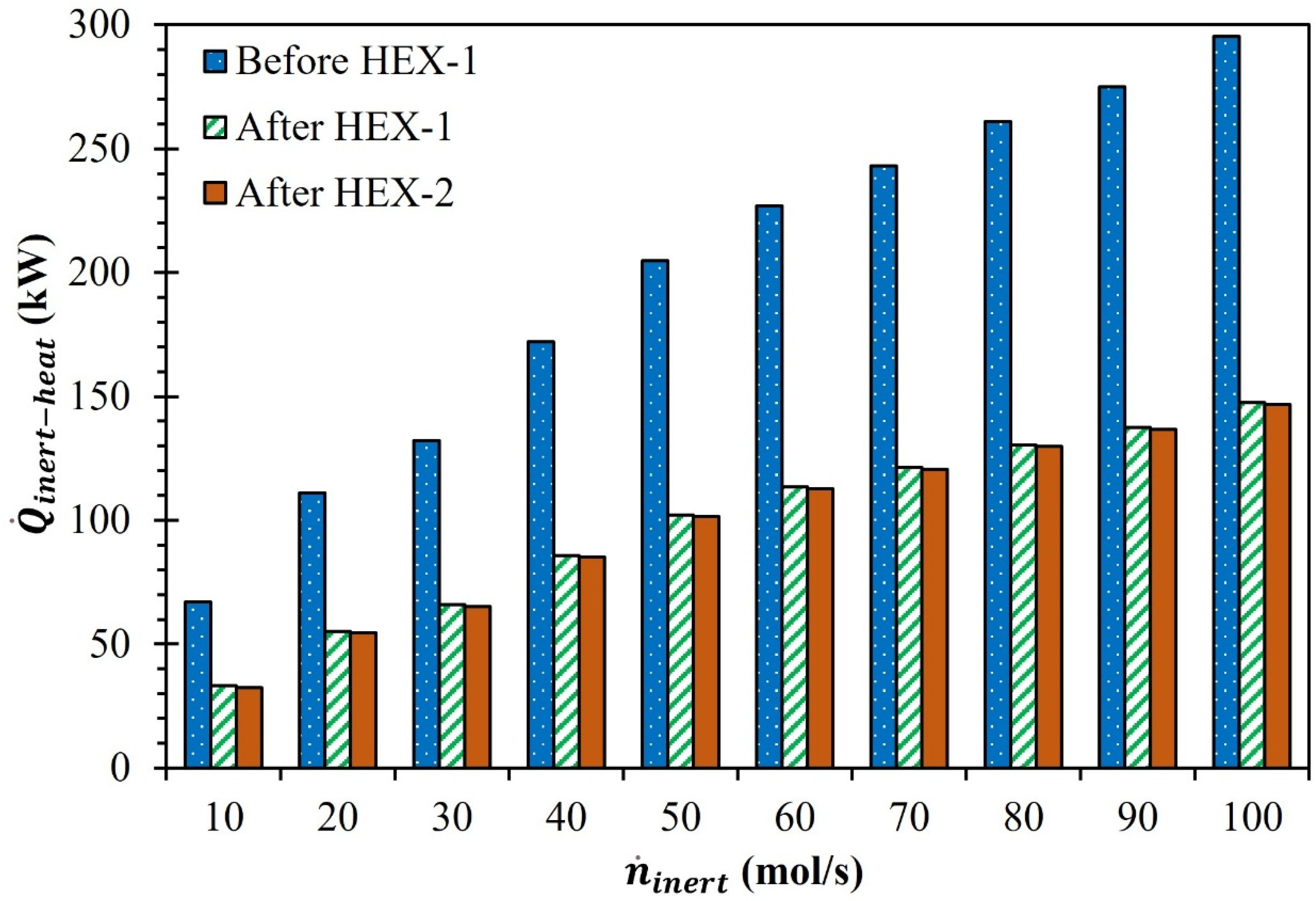
Table 2. Effect of n ˙ i n e r t on Q ˙ i n e r t h e a t and Q ˙ h e a t e r 1 (MgFe2O4/CDS cycle).
n ˙ i n e r t (mol/s) Q ˙ i n e r t h e a t
(kW)
Q ˙ h e a t e r 1 (kW)
1066.930.7
20111.052.8
30132.263.4
40172.183.4
50204.899.7
60227.0110.8
70243.0118.9
80261.1127.9
90275.0134.9
100295.2145.0
Table 3. Effect of n ˙ i n e r t on η a b s o r p t i o n and Q ˙ r e r a d (MgFe2O4/CDS cycle).
n ˙ i n e r t (mol/s) η a b s o r p t i o n (%) Q ˙ r e r a d (kW)
1091.817.8
2092.916.2
3093.614.9
4094.114.8
5094.315.2
6094.515.0
7094.814.6
8094.914.6
9095.114.4
10095.214.6
Disclaimer/Publisher’s Note: The statements, opinions and data contained in all publications are solely those of the individual author(s) and contributor(s) and not of MDPI and/or the editor(s). MDPI and/or the editor(s) disclaim responsibility for any injury to people or property resulting from any ideas, methods, instructions or products referred to in the content.

