Article

Preparation of CCF/MWCNT-OH/Graphite/Resin Composite Bipolar Plates Using Bi-Directional Interfacial Modification and Study of Their Performance Improvement and the Mechanism of Their Interfacial Bonding Improvement

Institute of Powder Metallurgy, Central South University, Changsha 410083, China
*
Author to whom correspondence should be addressed.
Submission received: 24 January 2025 / Revised: 11 March 2025 / Accepted: 14 March 2025 / Published: 19 March 2025

Abstract

:
Composite bipolar plates are a new class of material bipolar plates for PEMFCs. However, their application is limited by problems such as the difficulty of balancing their strength/conductivity properties. In this paper, by using surface-modified carboxylated short-cut carbon fibers and hydroxylated carbon nanotubes as well as PI resin, the interfacial bonding between the carbon-based filler and the resin is effectively improved under the premise of ensuring electrical conductivity, which enhances the flexural strength. The effect of the surface modification of the filler on the interfacial bonding between the filler and the PI resin is thoroughly investigated through molecular dynamics simulations. The mechanism for this improved bonding was also studied. Through the surface modification of the filler, the composite bipolar plates possessed a flexural strength of 49.06 MPa and a planar conductivity of 228.52 S/cm with the addition of 6% MWCNT-OH as well as 12% CCFs, which has the potential to be an optional substrate for composite bipolar plates.

1. Introduction

Due to the increased demand for sustainable energy, hydrogen is one of the candidates for efficient energy in the new era [1,2,3]. Proton exchange membrane fuel cells (PEMFCs) are highly efficient energy conversion devices that convert the chemical energy stored in hydrogen into electrical energy. They also have the advantage of being clean and noiseless [4,5,6,7,8]. However, many reports state that their high cost has always limited the large-scale application of PEMFCs [9,10,11,12]. The main cost of PEMFCs is contributed by the catalytic layer and the bipolar plate, which also forms the main mass composition of PEMFCs and has a significant impact on stack durability, mass specific power density, fuel cell internal resistance, stack hydrothermal management capability, and cell output power [13,14,15,16,17]. Thus, the development of a high-performance, durable, and cost-effective bipolar plate is essential for advancing the practical application of PEMFCs [18,19,20]. The bipolar plate in a PEMFC plays a role in the conduction current, mass and heat transfer, membrane electrode support, etc.; therefore, compared with ordinary structural materials, the bipolar plate also needs to have a high electrical conductivity, good mechanical properties, good hydrophobic properties, high thermal conductivity, airtightness, etc. [20,21,22,23]. In addition, due to the environment in which the PEMFC operates, it also needs to have good corrosion resistance, as poor corrosion resistance can lead to the internal contamination of the cell and even damage to other components such as the proton exchange membrane [24,25,26,27,28].
According to the different preparation substrates, bipolar plates are mainly divided into graphite bipolar plates, metal bipolar plates, and composite bipolar plates. Graphite has excellent electrical and thermal conductivity and was one of the first materials used to prepare bipolar plates. Graphite bipolar plates have a mature preparation process [29,30], and their electrical and thermal conductivity can meet the needs of PEMFCs. However, graphite also lacks strength, has high processing costs, and has other issues that limit its application [31,32]. Metal materials have better ductility, electrical conductivity, and mechanical properties and are ideal candidates for bipolar plate materials [33,34]. However, metal bipolar plates also have problems, such as poor corrosion resistance in the PEMFC operating environment. Using corrosion-resistant coatings will bring additional costs, which must be addressed at this stage [35,36]. Composite bipolar plates are mainly prepared from graphite and resin, with the properties of both graphite and resin. According to the existing reports, composite bipolar plates have both good corrosion resistance and good processability and show potential in electrical conductivity and mechanical properties [37,38,39,40]. However, due to the poor wettability between graphite and resin, uneven mixing, and other problems, composite bipolar plates currently do not have a significant advantage in electrical conductivity and mechanical properties, which is mainly due to the conjugate changes in electrical conductivity and mechanical properties with the content of the resin binder [41,42,43]. In order to solve the problems in composite bipolar plates, it is feasible to add a third type of filler other than graphite and resin, such as carbon fiber [44,45,46], carbon nanotubes [47,48], carbon black [49,50], graphene [51], etc.
Much work has been done in recent years on the modification of composite bipolar plates using nanofillers. Choi H [45] et al. used a pure woven carbon fiber plate for the preparation of composite bipolar plates and deposited a conductive layer to increase its conductivity; such laminates have both good conductivity and mechanical properties. Lv [46] et al., on the other hand, used carbon fibers as dopants to enhance the performance of graphite/resin composite bipolar plates, in which the carbon fibers were surface-modified to enhance their wettability. Madheswaran D K et al. [47] investigated an MWCNT-infused polyaniline composite bipolar plate, which exhibited a flexural strength of more than 40 MPa and a planar conductivity of more than 80 S/cm. Wei H et al. [48] investigated a composite bipolar plate utilizing MWCNT and CCFs for the synergistic enhancement of their properties, and thanks to the large aspect ratio of MWCNT to CCFs, the prepared composite bipolar plate reached a conductivity of 272.8 S/cm. At the same time, the flexural strength was enhanced to 43.1 MPa. Carbon black also has a significantly different structure compared to the two-dimensional MWCNTs and CFs, and it is also often used to improve the performance of composite bipolar plates. Xu G et al. [49] explored the application of CBs within a phenolic resin/graphite composite bipolar plate system, which exhibited a bending strength of 45.3 MPa and a conductivity of 331 S/cm, which is of high practical value.
This study selected short-cut carbon fibers (CCFs) and prepared MWCNT-coated graphite (MWCNT@G) as conductive fillers to improve the performance of polyimide/graphite composite bipolar plates. A subsequent surface treatment of the short-cut carbon fibers and MWCNTs was used to prepare carboxylated short-cut carbon fibers (CCFs-COOH) and hydroxylated multi-walled carbon nanotubes (MWCNT-OH) with improved wettability with the resin. Composite bipolar plates with a balance of mechanical and electrical conductivity properties were prepared by more tightly binding with the PI resin, and the materials had balanced mechanical and electrical conductivities. The interfacial binding energy, cohesive energy density, diffusion coefficient, and other parameters were calculated by studio software to clarify the improvement mechanism.

2. Materials and Methods

2.1. Materials

Concentrated sulfuric acid (98%, CP, H2SO4), concentrated nitric acid (CP, HNO3), cobalt nitrate hexahydrate (Co(NO3)2·6H2O), sodium meta-aluminate (CP, NaAlO2), and sodium hydroxide (CP, NaOH) were all purchased from Aladdin Reagent (Shanghai, China) Ltd., and the PI resin (characteristic viscosity of 0.5~0.8 dL/g) was purchased from Zhongcheng Plastic (Guilin, China) Co., Ltd. The short-cut carbon fibers (CCFs, 3 mm) were purchased from Toray, Tokyo, Japan.

2.2. Preparation of CCFs-COOH and MWCNT-OH@G

As shown in Figure 1, CCFs-COOH were prepared by adding CCFs to a mixed solution of HNO3/H2SO4 (pre-mixed v(HNO3):v(H2SO4) = 1:3 and heated to 80 °C) by stirring them in. After 20 min, they were then filtered, washed, and dried to obtain CCFs-COOH with oxidized surfaces. The preparation of MWCNT-OH@G, on the other hand, was obtained by a three-step method: ① Cobalt nitrate was loaded onto the graphite surface by solution ultrasonication, filtered, and dried; ② Graphite coated with MWCNT on the surface, i.e., MWCNT@G, was prepared at 800 °C (acetylene: hydrogen: nitrogen = 30: 5: 300 sccm) by chemical vapor deposition; and ③ Graphite coated with MWCNT on the surface, i.e., MWCNT@G, was prepared using the MWCNT-OH method, MWCNT@G was placed in a mixed solution of NaAlO2 and NaOH, and the temperature was raised to 80 °C for a period of immersion to obtain MWCNT-OH@G material with ultrasonic dispersion [52].

2.3. Preparation of Composite Bipolar Plates

The MWCNT-OH@G and CCFs-COOH obtained in Section 2.2 were mixed with PI resin and graphite powder. The obtained mixed powders were put into a 60 × 60 mm mold and hot-pressed at 230 °C and 15 MPa pressure. In order to prevent the prepared composite BPs from sticking to the molds, polytetrafluoroethylene (PTFE) paper was used during the preparation process to facilitate the release of the molds. The sample numbers and compositions of the prepared composite BPs are listed in Table 1. The proportion of resin was fixed at 25%, the carbon-based filler replaced part of the graphite, and the sum of carbon-based filler and graphite was fixed at 75%.

2.4. Means of Characterization and Detection

XRD (Rigaku, Nihon Rikaku Corporation, Tokyo, Japan) and Raman spectroscopy (Thermo Fischer DXR, Thermo Fischer DXR, Thermo Fisher Scientific, Wuhan, China) were combined to study the effect of surface treatment on the properties (graphitization and crystallinity) of MWCNT and CCF; XPS (PHI-5000versaprobeIII, ULVCA-PHI, Nanjing, China) was used to study the changes in surface elemental content before and after surface treatment; and infrared spectroscopy (FT-IR, Bruker Vertex 70, Bruker, Karlsruhe, Germany) was used to study changes in chemical groups before and after surface treatment. In order to investigate the properties of the bipolar plates, the electrical conductivity of the composite bipolar plates was tested using ST-2258C four-point probe (China Lattice Electronics Corporation, Suzhou, China), the flexural strength was examined using Instron3369 material mechanics tester (Engstrom Corporation, Boston, MA, USA), and the contact angle was tested using Dataphysics OCA20 hydrophobicity tester (Beijing Audrino Instrument Co., Ltd., Beijing, China). A scanning electron microscope (SEM, Hitachi Regulus8100, Hitachi, Tokyo, Japan) was used to observe the microscopic morphology, and in order to investigate the durability of the composite bipolar plates in the PEMFC operating environment, corrosion resistance tests were conducted using an electrochemical test bench (CHI 660E, Shanghai Chenhua Instruments, Shanghai, China) under the following conditions: a kinetic potential polarization of −0.5~0.9 V in a solution whose pH = 3, a scanning rate of 0.01 V/s, −0.1 V/+0.6 V with constant potential polarization, and a polarization time of 18,000 s. The software used to simulate molecular dynamics, Materials Studio, is a 2020 release, and the specific simulation parameters and methods used are detailed later.

3. Results and Discussion

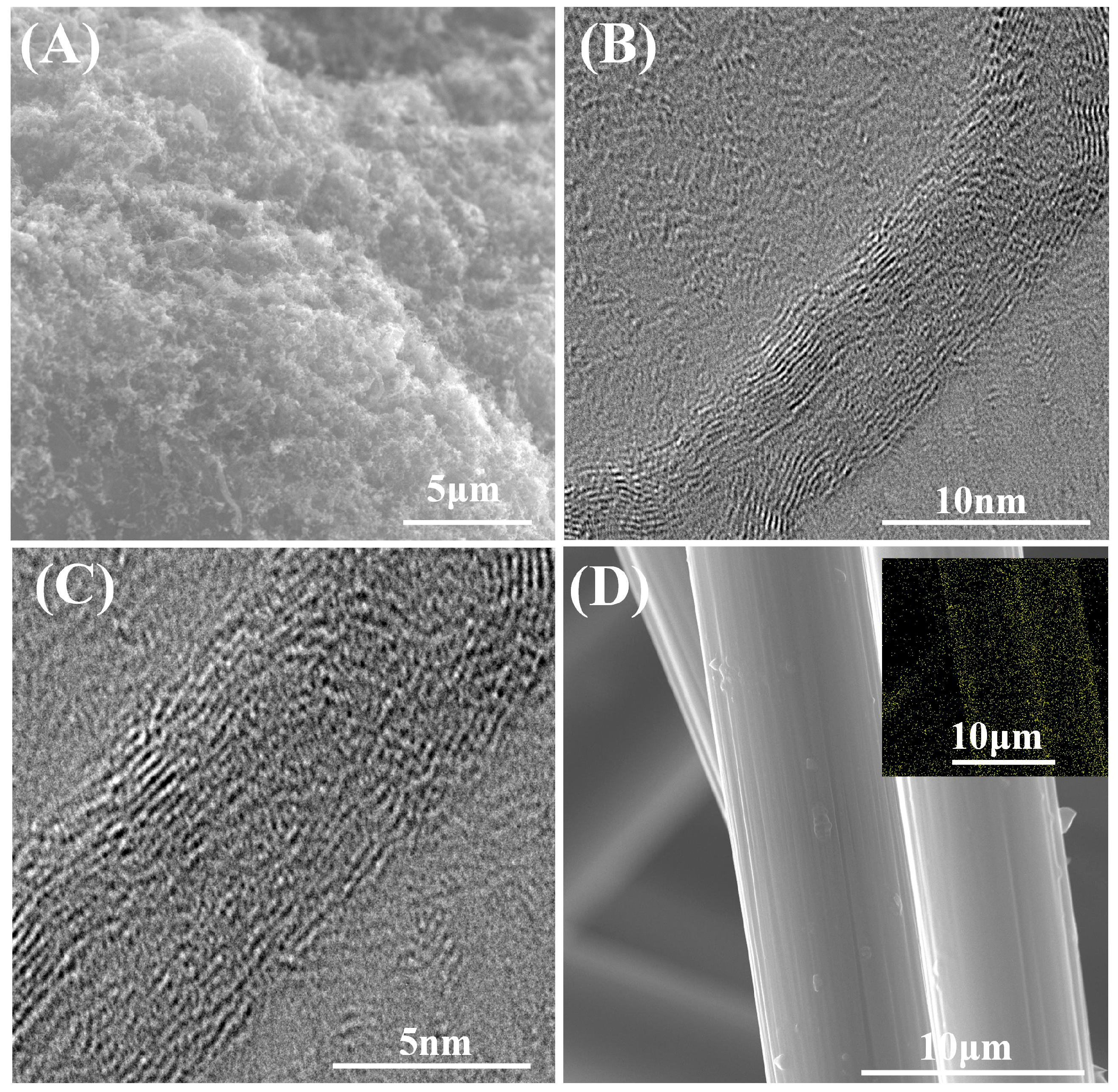
3.1. Effect of Surface Modification on the Properties of MWCNTs and CCFs

In order to investigate the effect of surface modification on CCFs and MWCNTs, as well as to verify the success of the reaction, the samples were tested using FT-IR, XPS, Raman spectroscopy, and XRD, and the results are shown in Figure 2.
Figure 2a shows the FT-IR map of the sample to characterize the generation of the corresponding functional groups during carboxylation and hydroxylation. The peak at νs = 1624.73 cm−1 is typical of the -OH group stretching pattern in the C=C-OH form [53]. The broad peaks located at 3300~3500 cm−1 are typical of the stretching vibrational modes of the -OH group. In contrast, the peak on CCFs-COOH located at 1725.68 cm−1 is a typical C=O characteristic peak. Therefore, from the results of the IR spectra, the treatment of CCFs with HNO3/H2SO4 has characteristic peaks corresponding to carboxyl groups, whereas the treatment of MWCNTs with NaOH produces MWCNT-OH with -OH groups.
Figure 2b demonstrates the Raman spectra of the two carbon materials before and after treatment, and the change in the graphitization of the samples can be obtained by comparing the intensity of the d peak at 1300 cm−1 with that of the g peak at 1580 cm−1. The larger ratio between the two indicates that the more defects in the material, the lower the graphitization degree, which has an important effect on the electrical/thermal conductivity. From the results, the graphitization of the CCFs-COOH and MWCNTs-OH obtained after the treatment decreased compared to the CCFs and MWCNTs before the treatment, which is attributed to the fact that oxidizing strong acids as well as strong bases destroy the crystal structure of the materials and form defects connecting the carboxyl/hydroxyl groups, which leads to the decrease in graphitization. However, in comparison, the decrease in graphitization of MWCNT-OH relative to MWCNT is not as significant as that of CCFs-COOH relative to CCFs. This may be because the concentrated nitric acid/sulfuric acid mixture solution is more destructive to the material’s crystal structure.
Figure 2c illustrates the XRD images of the samples before and after treatment, and the graphitization degree (GD) of the samples was calculated according to the following equation [54].
d 002 = λ 2 sin θ
G D = 0.3440 d 002 0.3440 0.3354
where λ is the wavelength of the radioactive source, θ is the diffraction angle, and d002 is the crystallographic spacing of the graphite 002 crystal faces. The integrity of the crystals of the carbon material samples is obtained by comparing them with the d002 of the perfect graphite crystals as well as with the d002 of the amorphous carbon. From the results in Figure 2b,c, it can be seen that the graphitization degree of CCFs-COOH and MWCNTs-OH obtained after the treatment is reduced compared with that of CCFs and MWCNTs before the treatment, which is due to the fact that oxidizing strong acids and strong bases disrupted the crystalline structure of the materials and formed defects between carboxyl/hydroxyl groups, which led to the reduction of the graphitization degree. Comparatively, the treatment of strong bases was more obvious for the reduction of graphitization degree, which may be due to the higher reactivity of MWCNTs with high chemical activity itself.
Finally, the samples were examined by XPS, and the relative weights of the oxygen and carbon contents on their surfaces were investigated. It can be found that the surface oxygen content of the CCFs-COOH is very large. This indicates that HNO3/H2SO4 has a high degree of destruction of the graphite structure on its surface. And less consistent with is the graphitization degree detection results, the content in MWCNTs-OH is much less, which may be due to the fact that XPS focuses more on detecting the elemental distribution on the surface.
In order to investigate the effect of surface modification on the microstructure of the samples, the samples were tested using SEM and high-resolution TEM. The results are shown in Figure 3. From the SEM image in Figure 3A, it can be found that MWCNT is still encapsulated on the graphite surface after the deposition and NaOH/NaAlO2 treatment without any phenomena, such as detachment, being apparent. From the TEM images of Figure 3B,C, it can be found that the lattice stripes of carbon nanotubes are no longer continuous after the treatment. This indicates that the crystal structure is destroyed after the intense alkali treatment, which may negatively affect the intrinsic electrical conductivity. Figure 3D demonstrates the surface of CCFs-COOH and the EDS MAPPING plots of O. After the HNO3/H2SO4 treatment, the oxygen content of the surface increases substantially.

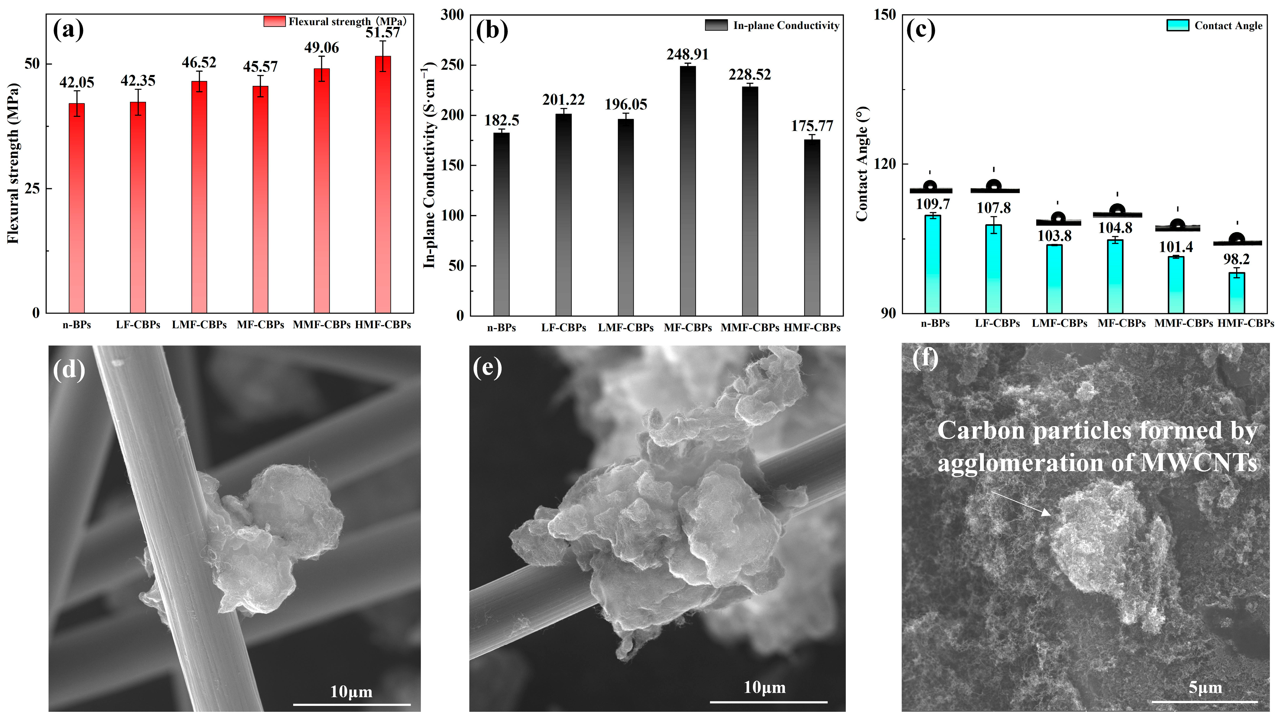
3.2. Effect of Surface Modification on the Performance of Composite Bipolar Plates

In order to study the effect of filler interface modification on the key performance of bipolar plates, the conductivity, mechanical properties, and hydrophobicity of the composite bipolar plates were studied. When the filler content was low, at 9% (3% MWCNT + 6% CCFs), the flexural strength of the surface-treated LMF-CBPs increased to 46.52 ± 2.08 MPa, which was significantly improved compared to that of the LF-CBPs without surface-treated fillers, 42.35 ± 2.62 MPa, which meets the DOE requirements for 2025. When the filler content was medium (6% MWCNT + 12% CCFs), the flexural strength of the modified component increased to 49.06 MPa, while that of the unmodified component was 45.57 MPa. At this filler content, the flexural strength of the unmodified filler is still not as high as that of the modified filler. After that, as the content of the surface-treated filler increased, the flexural strength continued to increase, but the degree of improvement decreased. When the content of MWCNTs and CCFs in HMF-CBPs was increased to 25%, the flexural strength could be increased to 51.57 ± 3.07 MPa, which is close to 20% higher, compared with that of the n-BPs without any filler, 42.05 ± 2.55 MPa. However, compared with MMF-CBPs at a medium filler content, the increase was not obvious. The improvement in flexural strength is attributed to the improvement in the interfacial bonding and wettability between CCFs-COOH, MWCNT-OH, and the PI resin, which allows the nanofillers to disperse better and bear external forces easier. In addition, due to the interfacial properties, the bonding at the fragile interface of the composite material is also more stable, so the improvement in mechanical properties is very obvious. The results show that the untreated pure MWCNTs and CCFs also have a certain improvement in flexural strength. This is because MWCNTs and CCFs themselves have good intrinsic properties, and one-dimensional nanofillers can better transfer stress [54], thereby improving the flexural strength of the composite bipolar plate. Overall, the improvement in wettability leads to a tighter bond between MWCNT-OH, CCFs-COOH, and the PI resin, forming a “reinforced concrete” structure as shown in Figure 4d,e, which results in a greater improvement in flexural strength.
MWCNTs and CCFs are often used as additives to enhance conductivity because their larger aspect ratio can connect the conductive areas of the composite material and build a perfect conductive path, thereby improving the conductivity of the composite bipolar plate. From the conductivity test results of 4-b, the addition of MWCNT-OH/CCFs-COOH leads to a marked improvement in conductivity, but the effect is not as good as that of pure MWCNT/CCFs. Although the surface treatment improves the wettability of the resin, the conductivity itself will be affected due to the reduction in the degree of graphitization, so the improvement in conductivity is not obvious. At a low filler content, the untreated filler has a planar conductivity of 201.22 S/cm, while the treated filler has only 196.05 S/cm. At a medium filler content, the MMF-CPBs of the component with modified fillers are 228.52 S/cm, while those of the MF-CBPs are 248.91 S/cm. Compared with those of n-BP (182.5 S/cm), this improvement is significant and meets the DOE requirements for 2025. However, as the filler content increases further, the conductivity of the composite bipolar plate decreases. This is because too much surface-modified carbon-based filler replaces the highly conductive graphite, and CCFs and MWCNTs are more difficult to disperse at a high content, resulting in agglomeration and the formation of a loose granular structure, as shown in the SEM image in Figure 4f. As reported in many studies in the literature, the agglomeration of nanoscale fillers may have a negative effect on conductivity.
As far as the results at this stage are concerned, in terms of conductivity, before the agglomeration threshold, highly conductive fillers are favorable for conductivity improvements, regardless of whether the interface modification is carried out or not, but in a lateral comparison, the conductivity of the interface-modified bipolar plates decreases slightly compared with that of the unmodified ones, but there is still a significant improvement compared with that of the ones without fillers. The mechanical properties of the interface-modified filler increase, while the improvement of the mechanical properties of the unmodified ordinary filler is not obvious. But, considering that the composite bipolar plates need both better mechanical and electrical conductivity properties, the MMF-CBP samples have a better overall performance. In Table 2, the performance of the MMF-CBPs, for example, is compared with that of various composite bipolar plates prepared in the last two years.
Figure 4c illustrates the contact angle data for the composite bipolar plate, reflecting the hydrophobicity of the composite bipolar plate. Since the hydrophobic MWCNTs and CCFs were surface-treated to take on hydrophilic carboxyl and hydroxyl groups, the hydrophobicity decreased compared to the n-BPs from 109.7° to 101.4°. However, the samples still exhibited hydrophobicity (a hydrophobicity angle > 90°). However, the hydrophobicity angle decreases further with the further increase in filler content of the surface treatments, which may be due to the relatively higher filler content coming to the surface of the polar plate with the flow of resin during the molding process [59,60], which further reduces the hydrophobicity of the surface.
Overall, thanks to their improved wettability and interfacial properties, the MMF-CBPs demonstrated the best overall performance. The composite bipolar plates exhibited a flexural strength of 49.06 MPa and a planar conductivity of 228.52 S/cm with a content of 6% MWCNT-OH and 12% CCFs-COOH.

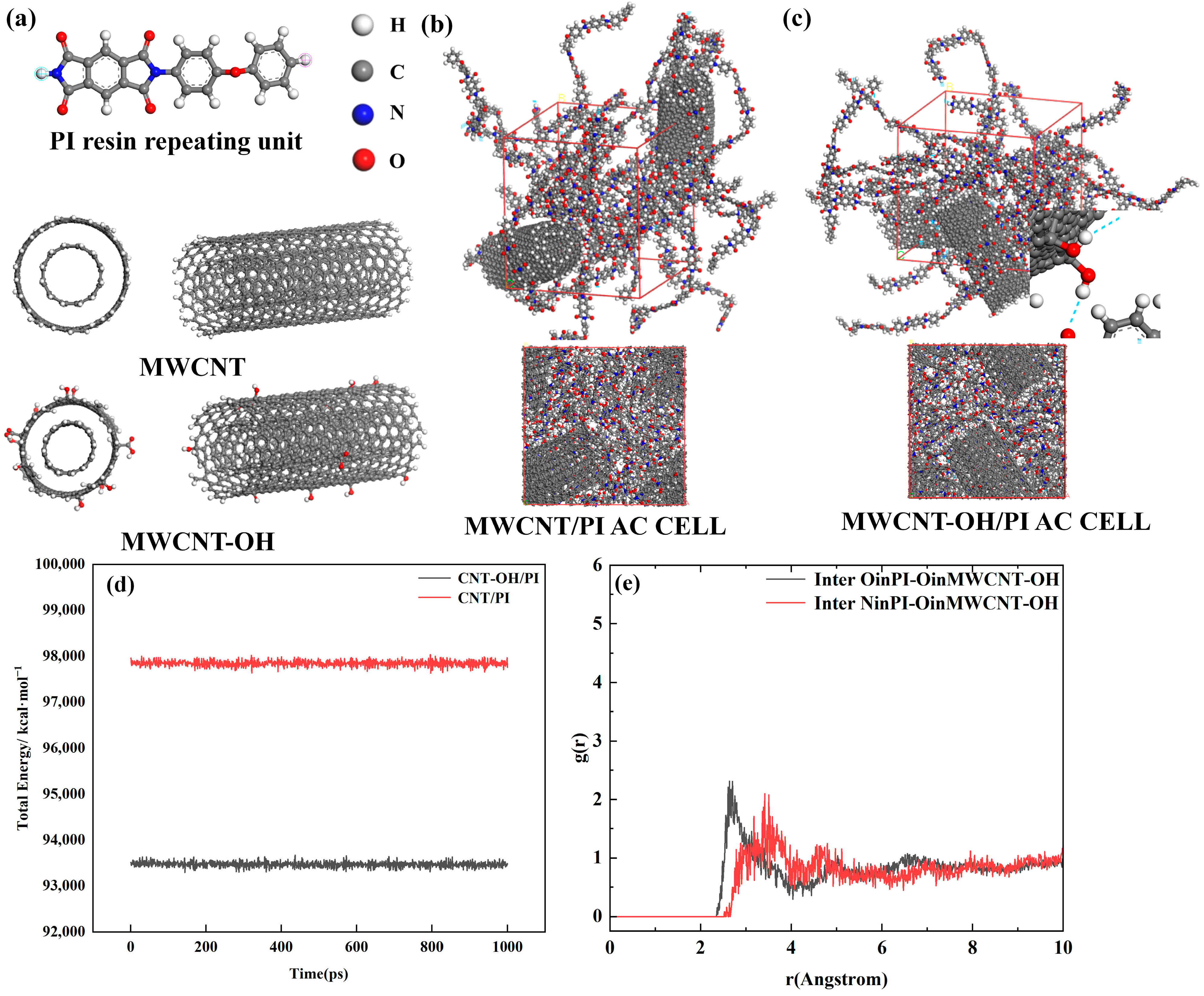
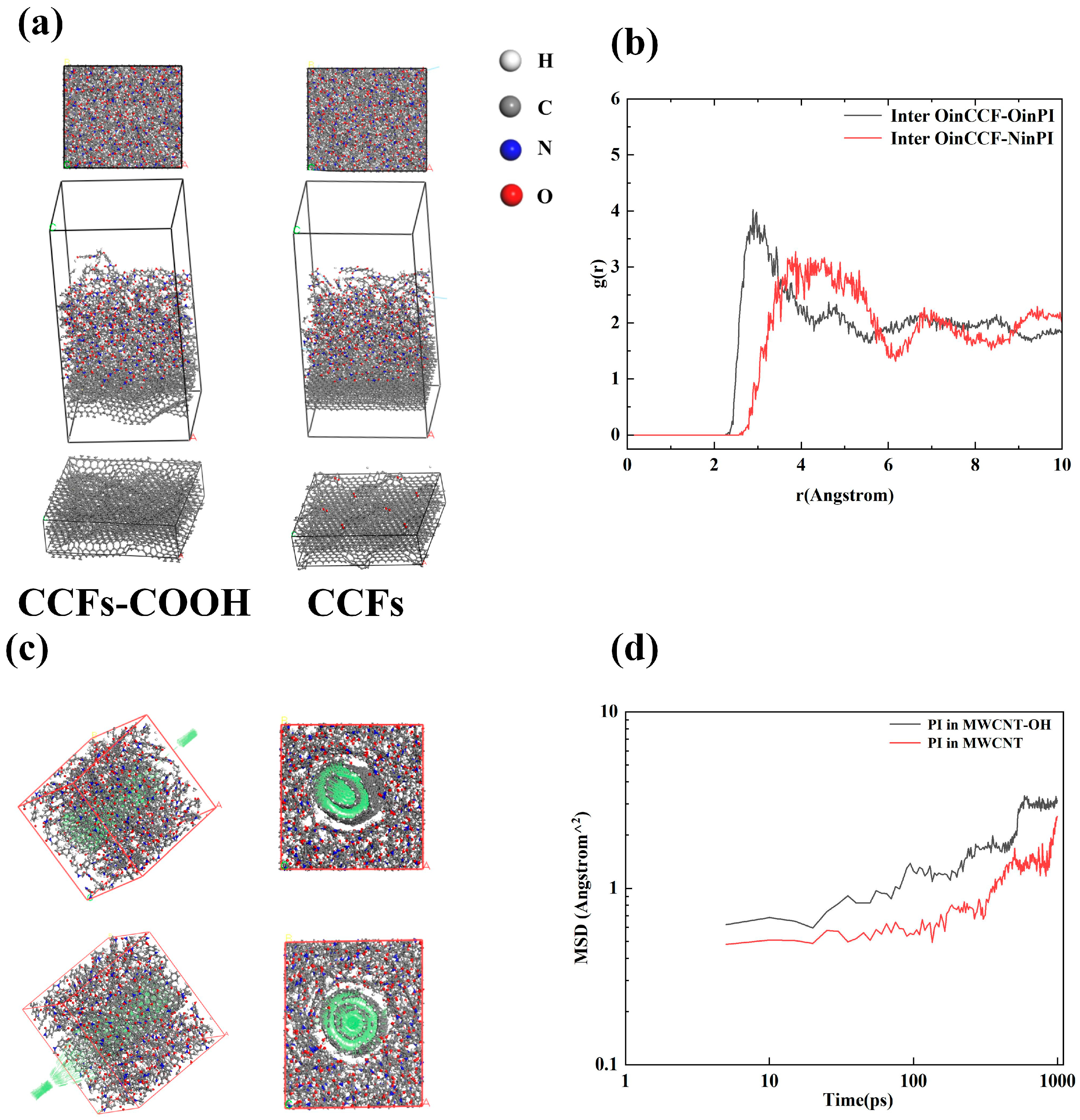
3.3. Investigation of the Mechanism of Improvement in the Performance of MWCNT-OH/CCFs-COOH Using MS Simulation

Considering that for composite systems such as graphite–resin–carbon nanotubes, the fracture failure is usually at the interface where the bonding is unstable, whereas the carbon nanotubes themselves are prepared in situ on graphite, which are in contact and adhered to the resin while constructing the conductive network. In addition, the literature on the need for multiple nanofillers has also shown that the lack of wettability of nanofillers with resin has resulted in the inability to fully utilize the performance of the nanofillers, which may even lead to a decrease in the overall performance of the material. Therefore, the interaction between carbon nanotubes and resins needs to be investigated to further illustrate the mechanism of interfacial modification for the improvement of wettability and bonding between carbon nanotubes and resins.
To further illustrate the improvement in the direct wettability and bond strength of the surface-modified filler with the resin, molecular dynamics simulations of the filler–resin interaction were performed using Materials Studio (MS). Figure 5a–c show the molecular models used during the study of PI and MWCNT-OH, demonstrating the structure of the PI resin monomer and the modeling of MWCNT/MWCNT-OH. Combined with the previous XRD as well as FT-IR results, a small amount of carbonyl group was added to the model of MWCNT-OH, and the ends were hydrogenated in order to minimize the edge effects of MWCNT. The length of a single PI molecular chain was 25 repeating units.
The steps for the molecular dynamics simulations are as follows. First, we use the COMPASS force field of the Forcite module in MS to optimize each molecular structure for 5000 steps to minimize the energy of the molecular structure. Then, we use the construct function of the Amorphous Cell module to model PI/MWCNTs and PI/MWCNTs to simulate the contact at the interface, in which the molecular number ratio of PI to MWCNT/MWCNT-OH is 12:2, the mass ratio of PI to MWCNT/MWCNT-OH is 35%:65%, the molecular number ratio of PI to MWCNT/MWCNT-OH is 12:2, and the mass ratio is 35%:65% as Figure 5b,c show. After the construction is completed, the overall structure is optimized again. After completing the above steps, the constructed model was annealed for 20 cycles in the temperature range of 300~500 K, and 5000 steps of structure optimization were continued in the last frame to relax the molecular chain of PI. Then, the molecular dynamics simulation was performed using the dynamics function of the Forcite module, in which the thermostat selected was NOSE, the Q ratio was 0.01, the barostat selected was Berendsen, and the decay constant was 0.1 ps. The time step in the simulation process was 1.00 fs, the duration was 1000 ps, and the number of steps was 1,000,000. The pressure used for NPT synthesis was 0.01 GPa, and then NVT was used to simulate the molecular dynamics of PI/MWCNT-OH.
The final conformations obtained were analyzed to calculate the binding energies of PI and MWCNT(-OH) using the following equations, respectively, in order to analyze the binding strength between MWCNT-OH and PI and to compare it with the binding energy between untreated MWCNT/PI. Figure 5b,c show the final conformation generated after the molecular dynamics tethering of the amorphous cell model previously constructed using the AC module, and Figure 5d shows that in the second half of the NVT, the energy of the system basically converges, indicating that the system is close to equilibrium. After the system has equilibrated, the interfacial binding energy between the resin and the carbon nanotubes is calculated using the following equation [61]:
E t o t a l = E t o t a l b o n d + E n o n b o n d + E c r o s s = ( E b + E θ + E φ ) + E v d W + E e l e c t r o s t a t i c + ( E c r o s s )
Here, Etotal−bond comprises the bond stretching energy, angle bending energy, and dihedral torsion energy. The non-bonded energy is composed of van der Waals energy and electrostatic energy. Ecross is the energy that arises from the effect of one bonded atom on another bonded atom, such as bond–angle and bond–bond cross terms.
E i n t e r f a c e a b = E a + b E t o t a l a E t o t a l b
In the equation, Einterface−ab is the binding energy between components a and b, Ea+b is the total energy of the composite system, and Ea, Eb are the total energies of components a and b. In the simulations of this work, Ea+b is the total energy of the PI resin with MWCNT(-OH), Ea is the total energy of MWCNT(-OH), and Eb is the total energy of the PI resin, which were calculated using the energy calculation function in Forcite, and the results are shown in Table 3.
From the calculated results, MWCNT-OH/PI has a more considerable binding energy in absolute value compared to MWCNT/PI, indicating a more solid binding between the two phases, with a binding energy of −1771.92 kcal/mol, which is 10% higher in absolute value compared to −1629.23 for MWCNT/PI. Moreover, in order to further illustrate that the combination between the two is more solid, the calculation function of the Forcite module was used to calculate the cohesive energy density (CED) and solubility parameter (SP) of the whole system [62,63], and the results are also listed in Table 3. The cohesive energy density characterizes the theoretical energy required to overcome the intermolecular forces to vaporize a unit volume of condensate, and the higher the cohesive energy density, the stronger the intermolecular group interactions. On the other hand, the solubility parameter is a parameter used to measure the phase solubility between polymers, and its value is calculated by referring to the following formula. The cohesive energy density of MWCNTs-OH/PI is 5.616 × 10⁸ J/m3, which is also more extensive compared to that of MWCNTs/PI, 5.328 × 10⁸ J/m3.
S P = C E D
As can be deduced from the final configuration in Figure 5c, it is possible that hydrogen bonds between N as well as C=O in MWCNT-OH and PI have been created, which have led to more solid bonds between MWCNT-OH and PI. Therefore, radial distribution function (RDF) calculations were carried out with reference to the following equations for the groups that may form hydrogen bonds.
g A B r = ρ b ( r ) ρ B ( r ) = N b ( r ) N B ( r )
gAB denotes the ratio of the probability of finding particle B in a spherical shell of radius r starting from the center of particle A to the probability that particle B is uniformly distributed throughout the system. It also denotes the ratio of the regional density of the particles in a periodic element to the global density. Figure 5e shows the RDF between O in CNT-OH and O, N in PI. Calculating the distance between the possible hydrogen bonding receptors can determine whether the interaction force is likely to be hydrogen bonding. If the first peak of the RDF falls between 2.5 and 3.1 Å [64], then it is a hydrogen bonding distance, and >3.1 Å is a strong van der Waals force. Figure 5e shows that the distance between O in MWCNT-OH and O on C=O in PI is 2.69 Å, and the distance between O and N in PI is 2.78 Å. From the statistical results of RDF and the calculation of MS interfacial binding energy, the interaction between MWCNT-OH and PI is indeed improved compared with MWCNT and PI, which is not only reflected in the binding energy, but also in CED, which may be attributed to the formation of hydrogen bonding between the hydroxyl group of MWCNT-OH and the N or C=O groups in PI. This is in general agreement with other results on the interaction of functionalized carbon nanotubes and resins [64].
Subsequently, the interface between CCFs and PI was investigated using a methodology consistent with that used to study the MWCNTs-OH/PI system. The surface of the CCFs was modeled using four layers of graphite crystals, while the surface graphite layer of the CCFs-COOH was randomly attached with carboxyl groups. The interface was constructed using the BUILD LAYER function that comes with the MS software (version 20.1), in which the thickness of the vacuum layer was 30 Å. The schematic of the final model is shown in Figure 6a. After the modeling of the interface between CCFs(-COOH) and PI was completed, a molecular dynamics simulation method similar to that of the MWCNT-OH/PI system was carried out, and after NPT, NVT simulations were performed using the same parameters, the PI and CCFs(-COOH) were calculated, and the results are shown in Table 4. The RDF calculations were also carried out and the results are shown in Figure 6b.
As can be seen from the results of Table 4 shows, more energy is released from the combination of the two, and the binding of PI with CCFs-COOH is more solid compared to that of pure CCFs. The interfacial binding energy of CCFs/PI is -805.42 kcal/mol as shown in Table 4, while the interfacial binding energy of CCFs-COOH/PI was calculated to be -898.97 kcal/mol. In addition, the total energy of the PI/CCFs-COOH system is lower compared to that of the PI/CCFs when using the same packing ratio of PI:CCF(-COOH). To further illustrate the mechanism of the wettability improvement between CCFs-COOH and PI, the RDF between C=O, -OH on the CCFs and N, O on the PI was calculated. The results are shown in Figure 6b. The results show a significant difference from the previous RDF between PI/MWCNT-OH, with the first peak of the RDF between O on CCFs and O on PI being 2.89 Å, while the first peak with N is 3.71 Å, indicating that only the C=O group on the PI resin can form hydrogen bonds with CCFs-COOH, while strong van der Waals forces dominate the N group. Finally, in order to study the motion of PI around a single MWCNT-OH, the packing function of the AC module of MS was used to build a model of MWCNT located at the center of the cell, as shown in Figure 6c. Molecular dynamics simulations were carried out, and the diffusion coefficients of the PI were subsequently calculated for the generated trajectory files according to the following equations [65]:
D = 1 6 lim t d ( M S D ) d t = 1 6 lim t d d t i = 1 N r t r ( 0 ) 2
where r is the distance of the beads, t is the simulation time, and N is the number of beads. After the calculation steps, the MSD curves of PI wrapped in MWCNT and MWCNT-OH were obtained.
From the MSD test results in Figure 6d, it can be seen that during the simulation at 1000 ps, the MSD curve of MWCNT-OH tends to flatten with time, while the MSD curve of MWCNT rises with time. The larger slope of MWCNTs-OH in the first half of the curve indicates that in the early stage, the PI is more motile around MWCNTs-OH, which may be due to the rise in motility caused by the improvement in wettability over a short distance. From the latter part of the curve, it can be seen that after a longer simulation time, the diffusion coefficient of PI molecules around MWCNT-OH becomes smaller than the diffusion coefficient of PI molecules around MWCNT, which suggests that after a longer physicochemical reaction time, the added MWCNT-OH can adsorb the PI chains, preventing the movement of PI, and reducing the mean square displacement. It is worth noting that although most papers attribute the improvement of the interfacial properties between polymers and carbon atoms to the reduction of MSD, i.e., the functional groups on the surface of the carbon nanotubes/carbon fibers restrict the movement of the polymer molecular chains, which results in stronger interfacial bonds [66,67]. However, in other studies in the literature, some authors have suggested that an increase in MSD increases the wettability improvement between PIs and functionalized carbon nanotubes [68,69], and this discrepancy may be due to the different time periods of the simulations discussed.
In summary, the results of the molecular dynamics simulations show that thanks to the formation of hydrogen bonds between MWCNT-OH and PI, a tighter bond was achieved between PI and MWCNTs, which also exhibited better wettability, a cohesive energy density, and better mobility of PI around MWCNT-OH. On the other hand, there is also a stronger bond between PI and CCFs-COOH compared to the non-surface-modified CCFs. Therefore, in general, after the filler modification, the weak interface of the composite material, the difficulties in wetting, and the problem of molecular bonding instability have been improved. Carbon nanotubes and other fillers can be fully wetted with resin to play a greater role under more stress, constructing conductive networks, etc., so that the overall performance of the material, especially its mechanical properties, is improved.

3.4. Corrosion Resistance of Composite Bipolar Plates

In order to verify the effect of interfacially modified fillers on the corrosion resistance of the composite bipolar plates, the samples were subjected to constant potential polarization tests (−0.1/+0.5 V), and the results are shown in Figure 7a,b. As can be seen from the results, for a constant potential polarization of −0.1 V, only the MF-CBPs and HMF-CBPs exhibited large currents after prolonged polarization. This is caused by the agglomeration of more small-sized carbon-based fillers at an excessive content. An excessive amount of small-sized fillers destroys the overall structure of the composite bipolar plate, which leads to an increase in the number of active sites where corrosion occurs [70,71]. The surprisingly high current density of HMF-CBPs may be due to the fact that the excess MWCNT-OH/CCFs-COOH has already agglomerated at this point, and the MWCNG-OH with CCFs-COOH exposed on the surface may also be more chemically active [72].
The trends of the kinetic potential polarization results in Figure 7c,d are generally consistent with those of the constant potential polarization results. The addition of nanofillers increases the corrosion current density of the molded composite bipolar plates since it destroys their surface structure. Thanks to the better corrosion resistance of the graphite/PI resin itself, the corrosion resistance of n-CBPs without any nanofillers, as well as the components with a small amount of CCFs/MWCNT@G and surface-modified nanofillers, is able to satisfy the DOE standard of 2025 (<10−6 A·cm−2) [73]. However, with a further increase in nanofillers, neither MF-CBPs nor HMF-CBPs meet the DOE criteria. As previously described, the corrosion current density tends to decrease more slowly with surface-modified nanofillers, and agglomeration occurs at higher filler contents because the surface modification improves wettability, enhances interfacial bonding, and slows agglomeration.

4. Conclusions

In this study, two surface-modified carbon-based fillers, MWCNT-OH and CCFs-COOH, were prepared to improve the poor wettability between carbon-based fillers and resin in composite bipolar plates. In addition, the researchers performed molecular dynamics simulations using Materials Studio software to investigate mechanisms for improvements. The results showed that MWCNT-OH effectively improved the interfacial bonding and cohesive energy density of the amorphous cells after mixing by forming hydrogen bonds with N and C=O in the PI resin; CCFs-COOH formed hydrogen bonds with C=O in the PI resin; and the fluidity of the PI resin around the MWCNT-OH was also improved. Through this enhancement, a composite bipolar plate meeting the requirements of DOE 2025 was prepared. With a ratio of 6% MWCNT-OH@G and 12% CCFs-COOH filler, the composite bipolar plate has a high flexural strength of 49.06 MPa, which is 7.6% higher than that for the same filler without interfacial modification (45.57 MPa) and 16% higher than that without any filler added (42.05 MPa). The plane conductivity can be up to 228.52 S/cm, compared with 182.5 S/cm without any filler, which is an increase of 25.2%. In addition, the composite bipolar plate’s corrosion resistance and hydrophobicity do not decrease very much because of the filler modification. Due to the excellent corrosion resistance of the substrate, the corrosion resistance of the bipolar plates also still meets the DOE’s 2025 requirements.

Author Contributions

Conceptualization, W.L. and Z.X.; methodology, W.L.; software, W.L.; validation, W.L.; formal analysis, W.L.; investigation, W.L.; resources, Z.X.; data curation, Z.X.; writing—original draft preparation, W.L. and H.Z.; writing—review and editing, W.L.; visualization, Z.X.; supervision, Z.X.; project administration, Z.X.; funding acquisition, Z.X. All authors have read and agreed to the published version of the manuscript.

Funding

This research received no external funding.

Data Availability Statement

The raw data supporting the conclusions of this article will be made available by the authors on request.

Conflicts of Interest

The authors declare no conflicts of interest.

Abbreviations

  • The following abbreviations are used in this manuscript:
MWCNTsMulti-walled carbon nanotubes
PEMFCProton exchange membrane fuel cell
CCFsChopped carbon fibers
CEDCohesive energy density
MSDMean square displacement
SPSolubility parameters
PIPolyimide resin
Requirements of DOERequirements of the U.S. Department of Energy

References

  1. Sazali, N. Emerging technologies by hydrogen: A review. Int. J. Hydrogen Energy 2020, 45, 18753–18771. [Google Scholar] [CrossRef]
  2. Jaradat, M.; Almashaileh, S.; Bendea, C.; Juaidi, A.; Bendea, G.; Bungau, T. Green Hydrogen in Focus: A Review of Production Technologies, Policy Impact, and Market Developments. Energies 2024, 17, 3992. [Google Scholar] [CrossRef]
  3. Baroutaji, A.; Arjunan, A.; Robinson, J.; Wilberforce, T.; Abdelkareem, M.A.; Olabi, A.G. PEMFC poly-generation systems: Developments, merits, and challenges. Sustainability 2021, 13, 11696. [Google Scholar] [CrossRef]
  4. Qasem, N.A.; Abdulrahman, G.A. A recent comprehensive review of fuel cells: History, types, and applications. Int. J. Energy Res. 2024, 2024, 7271748. [Google Scholar] [CrossRef]
  5. Aminudin, M.; Kamarudin, S.; Lim, B.; Majilan, E.; Masdar, M.; Shaari, N. An overview: Current progress on hydrogen fuel cell vehicles. Int. J. Hydrogen Energy 2023, 48, 4371–4388. [Google Scholar] [CrossRef]
  6. Wilberforce, T.; Olabi, A.; Muhammad, I.; Alaswad, A.; Sayed, E.T.; Abo-Khalil, A.G.; Maghrabie, H.M.; Elsaid, K.; Abdelkareem, M.A. Recovery of waste heat from proton exchange membrane fuel cells–A review. Int. J. Hydrogen Energy 2024, 52, 933–972. [Google Scholar] [CrossRef]
  7. Gupta, P.; Toksha, B.; Rahaman, M. A Critical Review on Hydrogen Based Fuel Cell Technology and Applications. Chem. Rec. 2024, 24, e202300295. [Google Scholar] [CrossRef]
  8. Bhandari, R.; Adhikari, N. A comprehensive review on the role of hydrogen in renewable energy systems. Int. J. Hydrogen Energy 2024, 82, 923–951. [Google Scholar] [CrossRef]
  9. Wang, Z.; Liu, Z.; Fan, L.; Du, Q.; Jiao, K. Application progress of small-scale proton exchange membrane fuel cell. Energy Rev. 2023, 2, 100017. [Google Scholar] [CrossRef]
  10. Kampker, A.; Ayvaz, P.; Schön, C.; Karstedt, J.; Förstmann, R.; Welker, F. Challenges towards large-scale fuel cell production: Results of an expert assessment study. Int. J. Hydrogen Energy 2020, 45, 29288–29296. [Google Scholar] [CrossRef]
  11. Wang, Y.; Pang, Y.; Xu, H.; Martinez, A.; Chen, K.S. PEM Fuel cell and electrolysis cell technologies and hydrogen infrastructure development–a review. Energy Environ. Sci. 2022, 15, 2288–2328. [Google Scholar] [CrossRef]
  12. Moreno, N.G.; Molina, M.C.; Gervasio, D.; Robles, J.F.P. Approaches to polymer electrolyte membrane fuel cells (PEMFCs) and their cost. Renew. Sustain. Energy Rev. 2015, 52, 897–906. [Google Scholar] [CrossRef]
  13. Gao, X.; Chen, J.; Xu, R.; Zhen, Z.; Zeng, X.; Chen, X.; Cui, L. Research progress and prospect of the materials of bipolar plates for proton exchange membrane fuel cells (PEMFCs). Int. J. Hydrogen Energy 2024, 50, 711–743. [Google Scholar]
  14. Tang, A.; Crisci, L.; Bonville, L.; Jankovic, J. An overview of bipolar plates in proton exchange membrane fuel cells. J. Renew. Sustain. Energy 2021, 13, 022701. [Google Scholar] [CrossRef]
  15. Yan, Q.; Lu, G.; Li, S.; Xie, J.; Li, Y. Effects of cathode enhanced cooling channels and microporous metal mesh on performance of open cathode air-cooled fuel cells. Int. J. Electrochem. Sci. 2025, 20, 100927. [Google Scholar]
  16. Yang, D.; Fortin, P.; Garg, H.; Andersson, M. The Influence of bipolar plate wettability on performance and durability of a proton exchange membrane fuel cell. Int. J. Hydrogen Energy 2024, 95, 1284–1298. [Google Scholar] [CrossRef]
  17. Pourrahmani, H.; Siavashi, M.; Yavarinasab, A.; Matian, M.; Chitgar, N.; Wang, L.; Van Herle, J. A review on the long-term performance of proton exchange membrane fuel cells: From degradation modeling to the effects of bipolar plates, sealings, and contaminants. Energies 2022, 15, 5081. [Google Scholar] [CrossRef]
  18. Xiong, K.; Wu, W.; Wang, S.; Zhang, L. Modeling, design, materials and fabrication of bipolar plates for proton exchange membrane fuel cell: A review. Appl. Energy 2021, 301, 117443. [Google Scholar] [CrossRef]
  19. Zhang, J.; Wang, Z.; Ding, H.; Pan, Z.; Huang, X.; Pan, X. Heat and mass transfer characteristics of a novel three-dimensional flow field metal bipolar plate for PEMFC by laser 3D printing. Int. J. Hydrogen Energy 2024, 50, 1036–1049. [Google Scholar]
  20. Liu, J.; Zhang, L.; Yuan, B.; Zhang, Y.; Yang, Z.; Huang, J. Design and development of coating for metallic bipolar plates in proton exchange membrane fuel cell (PEMFC): A review. Mater. Des. 2024, 246, 113338. [Google Scholar]
  21. Liu, Q.; Lan, F.; Zeng, C.; Chen, J.; Wang, J. A review of proton exchange membrane fuel cell’s bipolar plate design and fabrication process. J. Power Sources 2022, 538, 231543. [Google Scholar]
  22. San, F.G.B.; Isik-Gulsac, I. Effect of surface wettability of polymer composite bipolar plates on polymer electrolyte membrane fuel cell performances. Int. J. Hydrogen Energy 2013, 38, 4089–4098. [Google Scholar]
  23. Song, Y.; Zhang, C.; Ling, C.-Y.; Han, M.; Yong, R.-Y.; Sun, D.; Chen, J. Review on current research of materials, fabrication and application for bipolar plate in proton exchange membrane fuel cell. Int. J. Hydrogen Energy 2020, 45, 29832–29847. [Google Scholar]
  24. Hinds, G.; Brightman, E. Towards more representative test methods for corrosion resistance of PEMFC metallic bipolar plates. Int. J. Hydrogen Energy 2015, 40, 2785–2791. [Google Scholar]
  25. Asri, N.F.; Husaini, T.; Sulong, A.B.; Majlan, E.H.; Daud, W.R.W. Coating of stainless steel and titanium bipolar plates for anticorrosion in PEMFC: A review. Int. J. Hydrogen Energy 2017, 42, 9135–9148. [Google Scholar]
  26. Tawfik, H.; Hung, Y.; Mahajan, D. Metal bipolar plates for PEM fuel cell—A review. J. Power Sources 2007, 163, 755–767. [Google Scholar]
  27. Pozio, A.; Zaza, F.; Masci, A.; Silva, R. Bipolar plate materials for PEMFCs: A conductivity and stability study. J. Power Sources 2008, 179, 631–639. [Google Scholar]
  28. Antunes, R.A.; Oliveira, M.C.L.; Ett, G.; Ett, V. Corrosion of metal bipolar plates for PEM fuel cells: A review. Int. J. Hydrogen Energy 2010, 35, 3632–3647. [Google Scholar]
  29. Song, P.; Qiao, G.; Hu, X.; Xia, X.; Xu, G.; Deng, Z. Current status and research progress of bipolar plates for proton exchange membrane fuel cells. In Proceedings of the 2021 International Conference on Power System Technology (POWERCON), Haikou, China, 8–9 December 2021; pp. 202–208. [Google Scholar]
  30. Mao, X.; Li, Y.; Li, Y.; Zhu, D.; Yu, W.; Ji, Y.; Wang, D.; Hu, X. Simultaneous electrical and mechanical properties improvement for composite expanded graphite bipolar plate by incorporating surface-activated carbon black paving on the carbonized melamine foam skeleton. Compos. Sci. Technol. 2024, 257, 110822. [Google Scholar]
  31. Yuan, X.Z.; Wang, H.; Zhang, J.; Wilkinson, D.P. Bipolar plates for PEM fuel cells-from materials to processing. J. New Mater. Electrochem. Syst. 2005, 8, 257. [Google Scholar]
  32. Stein, T.; Ein-Eli, Y. Challenges and perspectives of metal-based proton exchange membrane’s bipolar plates: Exploring durability and longevity. Energy Technol. 2020, 8, 2000007. [Google Scholar] [CrossRef]
  33. Wu, S.; Yang, W.; Yan, H.; Zuo, X.; Cao, Z.; Li, H.; Shi, M.; Chen, H. A review of modified metal bipolar plates for proton exchange membrane fuel cells. Int. J. Hydrogen Energy 2021, 46, 8672–8701. [Google Scholar] [CrossRef]
  34. Xu, Z.; Qiu, D.; Yi, P.; Peng, L.; Lai, X. Towards mass applications: A review on the challenges and developments in metallic bipolar plates for PEMFC. Prog. Nat. Sci. Mater. Int. 2020, 30, 815–824. [Google Scholar] [CrossRef]
  35. Liu, R.; Jia, Q.; Zhang, B.; Lai, Z.; Chen, L. Protective coatings for metal bipolar plates of fuel cells: A review. Int. J. Hydrogen Energy 2022, 47, 22915–22937. [Google Scholar] [CrossRef]
  36. Matsuura, T.; Kato, M.; Hori, M. Study on metallic bipolar plate for proton exchange membrane fuel cell. J. Power Sources 2006, 161, 74–78. [Google Scholar]
  37. Mathew, C.; Naina Mohamed, S.; Devanathan, L.S. A comprehensive review of current research on various materials used for developing composite bipolar plates in polymer electrolyte membrane fuel cells. Polym. Compos. 2022, 43, 4100–4114. [Google Scholar]
  38. Jeong, K.I.; Oh, J.; Song, S.A.; Lee, D.; Lee, D.G.; Kim, S.S. A review of composite bipolar plates in proton exchange membrane fuel cells: Electrical properties and gas permeability. Compos. Struct. 2021, 262, 113617. [Google Scholar]
  39. Hui, C.; Liu, H.-B.; Li, J.-X.; Li, Y.; He, Y.-D. Characteristics and preparation of polymer/graphite composite bipolar plate for PEM fuel cells. J. Compos. Mater. 2009, 43, 755–767. [Google Scholar]
  40. Cunningham, B.D.; Huang, J.; Baird, D.G. Development of bipolar plates for fuel cells from graphite filled wet-lay material and a thermoplastic laminate skin layer. J. Power Sources 2007, 165, 764–773. [Google Scholar]
  41. Planes, E.; Flandin, L.; Alberola, N. Polymer composites bipolar plates for PEMFCs. Energy Procedia 2012, 20, 311–323. [Google Scholar] [CrossRef]
  42. Shojaei, S.; Rostami-Tapeh-Esmaeil, E.; Mighri, F. A review on key factors influencing the electrical conductivity of proton exchange membrane fuel cell composite bipolar plates. Polym. Adv. Technol. 2024, 35, e6301. [Google Scholar]
  43. Wang, X.; Qu, Z.; Yang, H.; Zhang, G.; Zhang, Y.; Liu, C. Collective enhancements on thermal-electrical and mechanical properties of graphite-based composite bipolar plates through the coupled manipulations of molding and impregnation pressures. Membranes 2022, 12, 222. [Google Scholar] [CrossRef] [PubMed]
  44. Darıcık, F.; Topcu, A.; Aydın, K.; Çelik, S. Carbon nanotube (CNT) modified carbon fiber/epoxy composite plates for the PEM fuel cell bipolar plate application. Int. J. Hydrogen Energy 2023, 48, 1090–1106. [Google Scholar]
  45. Choi, H.; Seo, D.J.; Choi, W.Y.; Choi, S.W.; Lee, M.H.; Park, Y.J.; Kim, T.Y.; Yoon, Y.G.; Yi, S.-C.; Jung, C.-Y. An ultralight-weight polymer electrolyte fuel cell based on woven carbon fiber-resin reinforced bipolar plate. J. Power Sources 2021, 484, 229291. [Google Scholar]
  46. Lv, B.; Shao, Z.; He, L.; Gou, Y.; Sun, S. A novel graphite/phenolic resin bipolar plate modified by doping carbon fibers for the application of proton exchange membrane fuel cells. Prog. Nat. Sci. Mater. Int. 2020, 30, 876–881. [Google Scholar]
  47. Madheswaran, D.K.; Thangavelu, P. MWCNT-infused polyaniline composite–based bipolar plates for proton exchange membrane fuel cells fabricated via 3D printing. Ionics 2024, 30, 6349–6368. [Google Scholar]
  48. Wei, H.; Chang, G.; Xu, S.; Liu, J. Muti-Filler Composites Reinforced with Multiwalled Carbon Nanotubes and Chopped Carbon Fibers for the Bipolar Plate of Fuel Cells. Energies 2024, 17, 1603. [Google Scholar] [CrossRef]
  49. Xu, G.; Du, X.; Chang, L.; Hu, X.; Song, J. Effect of molding temperature on the properties of phenolic resin/carbon black/graphite composite bipolar plates. J. Solid State Electrochem. 2024, 28, 2505–2513. [Google Scholar]
  50. Yue, L.; Deng, Z.F.; Tan, H.; Xu, G.Z.; Hu, X.; Song, J.; Zhang, G.Q.; Song, P.X.; Liu, X.T. Carbon Black Doped Graphite Composite Bipolar Plate Compounds for Improving Conductivity. In Materials Science Forum; Trans Tech Publications Ltd.: Zurich, Switzerland, 2023; pp. 3–17. [Google Scholar]
  51. Witpathomwong, S.; Okhawilai, M.; Jubsilp, C.; Karagiannidis, P.; Rimdusit, S. Highly filled graphite/graphene/carbon nanotube in polybenzoxazine composites for bipolar plate in PEMFC. Int. J. Hydrogen Energy 2020, 45, 30898–30910. [Google Scholar]
  52. Ling, X.-L.; Wei, Y.-Z.; Zou, L.-M.; Xu, S. Preparation and characterization of hydroxylated multi-walled carbon nanotubes. Colloids Surf. A Physicochem. Eng. Asp. 2013, 421, 9–15. [Google Scholar]
  53. Yang, D.; Guo, G.; Hu, J.; Wang, C.; Jiang, D. Hydrothermal treatment to prepare hydroxyl group modified multi-walled carbon nanotubes. J. Mater. Chem. 2008, 18, 350–354. [Google Scholar] [CrossRef]
  54. Jiang, F.; Liao, W.; Ayukawa, T.; Yoon, S.-H.; Nakabayashi, K.; Miyawaki, J. Enhanced performance and durability of composite bipolar plate with surface modification of cactus-like carbon nanofibers. J. Power Sources 2021, 482, 228903. [Google Scholar] [CrossRef]
  55. Wei, H.; Chang, G.; Shi, R.; Xu, S.; Liu, J. Preparation and properties of graphite/polypropylene composite material reinforced by chopped carbon fibers for proton-exchange membrane fuel cell bipolar plates. Fuel Cells 2023, 23, 60–74. [Google Scholar] [CrossRef]
  56. Mathew, C.; Boby, A.; Varghese, P.R.; Mohamed, S.N.; Lenin Singaravelu, D. Effect of multi-walled carbon nanotubes on the properties of Composite Bipolar Plate for Polymer Electrolyte Membrane Fuel Cells. Eng. Res. Express 2025, 7, 015552. [Google Scholar] [CrossRef]
  57. Yan, G.; Zhang, X.; Wei, L.; Lou, A.; Liu, Y.; Wang, S.; Zhao, N.; Li, Q. Study on the effects of nano-copper addition on the properties of epoxy resin/graphite composite bipolar plates. Int. J. Hydrogen Energy 2024, 69, 576–585. [Google Scholar]
  58. Yin, Q.; Sun, K.; Li, A.; Shao, L.; Liu, S.; Sun, C. Study on carbon nanotube reinforced phenol formaldehyde resin/graphite composite for bipolar plate. J. Power Sources 2008, 175, 861–865. [Google Scholar] [CrossRef]
  59. Thébault, M.; Kandelbauer, A.; Müller, U.; Zikulnig-Rusch, E.; Lammer, H. Factors influencing the processing and technological properties of laminates based on phenolic resin impregnated papers. Eur. J. Wood Wood Prod. 2017, 75, 785–806. [Google Scholar] [CrossRef]
  60. Friedrich, K. Mesoscopic aspects of polymer composites: Processing, structure and properties. J. Mater. Sci. 1998, 33, 5535–5556. [Google Scholar] [CrossRef]
  61. Zhang, W.; Deng, X.; Sui, G.; Yang, X. Improving interfacial and mechanical properties of carbon nanotube-sized carbon fiber/epoxy composites. Carbon 2019, 145, 629–639. [Google Scholar] [CrossRef]
  62. Li, Y.; Li, H.; Song, C.; Zhu, Z.; Ma, X. Molecular dynamics simulations of the micro mechanism of functionalized SiO2 nanoparticles and carbon nanotubes modified epoxy resin adhesives. Polym. Compos. 2025, 46, 1587–1603. [Google Scholar]
  63. Sharma, K.; Shukla, M. Molecular modeling of the mechanical behavior of carbon fiber-amine functionalized multiwall carbon nanotube/epoxy composites. New Carbon Mater. 2014, 29, 132–142. [Google Scholar] [CrossRef]
  64. Wang, X.; Chen, D.; Zhong, W.; Zhang, L.; Fan, X.; Cai, Z.; Zhu, M. Experimental and theoretical evaluations of the interfacial interaction between carbon nanotubes and carboxylated butadiene nitrile rubber: Mechanical and damping properties. Mater. Des. 2020, 186, 108318. [Google Scholar] [CrossRef]
  65. Guo, Y.; Zhang, D.; Zhang, X.; Wu, Y. Thermal properties and mechanical behavior of functionalized carbon nanotube-filled polypropylene composites using molecular dynamics simulation. Mater. Today Commun. 2023, 37, 107510. [Google Scholar] [CrossRef]
  66. He, C.; Xu, B.; Li, X. Effects of modified single-wall carbon nanotubes on the mechanical properties of polyvinyl alcohol composites by molecular dynamics simulation. Mater. Today Commun. 2023, 35, 105598. [Google Scholar] [CrossRef]
  67. Cui, J.; Zhao, J.; Wang, S.; Wang, Y.; Li, Y. Effects of carbon nanotubes functionalization on mechanical and tribological properties of nitrile rubber nanocomposites: Molecular dynamics simulations. Comput. Mater. Sci. 2021, 196, 110556. [Google Scholar] [CrossRef]
  68. Li, K.; Gu, B. Molecular dynamic simulations investigating the wetting and interfacial properties of acrylonitrile nanodroplets in contact with variously functionalized graphene sheets. Chemical Physics Letters 2020, 739, 137023. [Google Scholar] [CrossRef]
  69. Liu, X.; Li, M.; Feng, P.; Fan, X.; Yan, Z.; Jia, H.; Jian, X.; Song, Y.; Xu, J. An anchor-inspired interface for improving interfacial properties of carbon fiber-reinforced high-performance thermoplastic composites. Compos. Part B Eng. 2024, 283, 111654. [Google Scholar] [CrossRef]
  70. Aung, N.N.; Zhou, W.; Goh, C.S.; Nai, S.M.L.; Wei, J. Effect of carbon nanotubes on corrosion of Mg–CNT composites. Corros. Sci. 2010, 52, 1551–1553. [Google Scholar] [CrossRef]
  71. Konsta-Gdoutos, M.S.; Batis, G.; Danoglidis, P.A.; Zacharopoulou, A.K.; Zacharopoulou, E.K.; Falara, M.G.; Shah, S.P. Effect of CNT and CNF loading and count on the corrosion resistance, conductivity and mechanical properties of nanomodified OPC mortars. Constr. Build. Mater. 2017, 147, 48–57. [Google Scholar] [CrossRef]
  72. Wang, F.; Liu, X.; Cao, B.; Wang, X.; Dong, K. Influence of the Dispersion of Carbon Nanotubes on the Electrical Conductivity, Adhesion Strength, and Corrosion Resistance of Waterborne Polyurethane Composites. Coatings 2024, 14, 1108. [Google Scholar] [CrossRef]
  73. Drive, U. Fuel Cell Technical Team Roadmap; US Drive Partnership: New York, NY, USA, 2013; pp. 1–26. [Google Scholar]
Figure 1. Schematic diagram of the preparation steps for composite bipolar plates.
Carbon 11 00024 g001
Figure 2. (a) FT-IR, (b) Raman spectra, (c) XRD, (d) XPS of the carbon-based fillers before and after surface treatment.
Carbon 11 00024 g002
Figure 3. (A) Surface morphology of MWCNT-OH@G, (B) TEM image of lattice fringes of MWCNT-OH, (C) Enlarged TEM image of lattice fringes of MWCNT-OH, and (D) SEM image of the surface of CCFs-COOH along with EDS mapping of the O elements.
Carbon 11 00024 g003
Figure 4. (a) Flexural strength of composite bipolar plate, (b) planar conductivity of composite bipolar plate, (c) hydrophobicity angle of composite bipolar plate, (d,e) SEM images of MWCNT-OH tightly bound to CCFs-COOH, and (f) particle structure formed by agglomeration of small-sized nanofillers.
Carbon 11 00024 g004
Figure 5. (a) Molecular model of PI resin and MWCNT(-OH), (b) PI/MWCNT amorphous unit cell model, (c) PI/MWCNT-OH amorphous unit cell model, (d) Energy change of the system in the last 100 ps of molecular dynamics, (e) Radial distribution function between O of MWCNT-OH and O, N of PI.
Carbon 11 00024 g005
Figure 6. (a) Modeling of the interface between CCFs(-COOH) and PI, (b) RDF of oxygen in CCFs-COOH with N and O in PI, (c) Model used to calculate diffusion coefficients of PI around MWCNTs, (d) MSD of PI around MWCNTs.
Carbon 11 00024 g006
Figure 7. (a) Constant potential polarization results for −0.1 V, (b) Constant potential polarization results for +0.5 V, (c) Kinetic potential polarization results, and (d) Corrosion potentials and corrosion current densities obtained from Tafel curves.
Carbon 11 00024 g007
Table 1. List of raw material ratios for composite bipolar plates.
SampleFillersResinGraphite
n-BPs-25%PI75%EG
LF-CBPs3% MWCNT@G + 6%CCFs25%PI66%EG
LMF-CBPs3% MWCNT-OH@G + 6%CCFs-COOH25%PI66%EG
MF-CBPs6% MWCNT@G + 12%CCFs25%PI57%EG
MMF-CBPs6% MWCNT@G + 12%CCFs25%PI57%EG
HMF-CBPs10%MWCNT-OH@G + 15%CCF-COOH25%PI50%EG
Table 2. Performance comparison of composite bipolar plates.
Performance of Composite Bipolar Plates with Added Nanofillers
MaterialsIn-Plane Electrical Conductivity
S/cm
Flexural StrengthReference/Note
CCFs-COOH/MWCNT-OH/PI/Graphite228.5249.06This work
CCFs/Graphite/PP189.430.2[55]
CCFs/Graphite/MWCNT/PF272.843.1[48]
PANI/Graphite/MWCNTs80.1540[47]
MWCNT/CB/NFG/EPR18246[56]
Nano-Co/EP/Graphite168.146[57]
Fenton-Treated CNT/PF/Graphite145.268.6[58]
Table 3. Calculation results of the CNT/PI, CNT-OH/PI.
SampleEa (kcal/mol)Eb (kcal/mol)Ea+b (kcal/mol)Einterface−ab (kcal/mol)Cohensive Energy Density (J/m3)Solubility Parameter (J/cm3)0.5
CNT/PI100,396.36−1003.0797,764.06−1629.235.33 × 10821.60
CNT-OH/PI97,098.83−1849.3493,477.57−1771.925.67 × 10823.81
Table 4. Calculation results of CCFs(-COOH)/PI.
-Ea (kcal/mol)Eb (kcal/mol)Ea+b (kcal/mol)Einterface−ab (kcal/mol)
CCFs/PI181,291.37−2294.70184,391.49−805.42
CCFs-COOH/PI157,136.89−2199.16160,234.13−898.97
Disclaimer/Publisher’s Note: The statements, opinions and data contained in all publications are solely those of the individual author(s) and contributor(s) and not of MDPI and/or the editor(s). MDPI and/or the editor(s) disclaim responsibility for any injury to people or property resulting from any ideas, methods, instructions or products referred to in the content.

