Article

Soot and Flame Structures in Turbulent Partially Premixed Jet Flames of Pre-Evaporated Diesel Surrogates with Admixture of OMEn

by
Steffen Walther
1,2,*,
Tao Li
1,
Dirk Geyer
2,
Andreas Dreizler
1 and
Benjamin Böhm
1
1
Department of Mechanical Engineering, Reactive Flows and Diagnostics, Technical University of Darmstadt, Otto-Berndt-Str. 3, 64287 Darmstadt, Germany
2
Optical Diagnostics and Renewable Energies (ODEE), Hochschule Darmstadt, Schöfferstraße 3, 64295 Darmstadt, Germany
*
Author to whom correspondence should be addressed.
Fluids 2024, 9(9), 210; https://doi.org/10.3390/fluids9090210
Submission received: 31 July 2024 / Revised: 4 September 2024 / Accepted: 7 September 2024 / Published: 10 September 2024
(This article belongs to the Special Issue Turbulence and Combustion)

Abstract

In this study, the soot formation and oxidation processes in different turbulent, pre-evaporated and partially premixed diesel surrogate flames are experimentally investigated. For this purpose, a piloted jet flame surrounded by an air co-flow is used. Starting from a defined diesel surrogate mixture, different fuel blends with increasing blending ratios of poly(oxymethylene) dimethyl ether (OME) are studied. The Reynolds number, equivalence ratio, and vaporization temperature are kept constant to ensure the comparability of the different fuel mixtures. The effects of OME addition on flame structures, soot precursors, and soot are investigated, showing soot reduction when OME is added to the diesel surrogate. Using chemiluminescence images of C2 radicals (line of sight) and subsequent Abel-inversion, flame lengths and global flame structure are analyzed. The flame structure is visualized by means of planar laser-induced fluorescence (PLIF) of hydroxyl radicals (OH). The spatial distribution of soot precursors, such as polycyclic aromatic hydrocarbons (PAHs), is simultaneously measured by PLIF using the same excitation wavelength. In particular, aromatic compounds with several benzene rings (e.g., naphthalene or pyrene), which are known to be actively involved in soot formation and growth, have been visualized. Spatially distributed soot particles are detected by using laser-induced incandescence (LII), which allows us to study the onset of soot clouds and its structures qualitatively. Evident soot formation is observed in the pure diesel surrogate flame, whereas a significant soot reduction with changing PAH and soot structures can be identified with increasing OME addition.

1. Introduction

The oxygenated poly(oxymethylene) dimethyl ether (OME) is an attractive clean diesel fuel or fuel additive because it suppresses the formation of soot. OMEn, with the general molecular structure of CH3O(CH2O)nCH3 and a chain length of n = 3, 4, is miscible with diesel fuel, enabling market introduction without building a new logistic infrastructure, and has a suitable high molecular weight (low vapor pressure) and viscosity, allowing for direct use in existing diesel engines [1]. Another key advantage is that OME obtained as e-fuel from renewable energy is carbon dioxide (CO2) neutral.
Soot formation in diesel combustion is initiated by the ignition of premixed fuel-rich regions that do not burn out completely due to the lack of oxygen (O2). Oxygenated fuels reduce the production of soot precursors in fuel-rich flames. The C-O bond survives fuel-rich ignition intact, so less carbon is available for soot formation in the oxygen-deficient region after ignition. The activated methylene groups present in the chemical structure of OME, which are bonded to oxygen atoms (-O-CH2-), lead to the formation of hydroperoxides at an early stage of combustion. These decompose into hydroxyl radicals (OH), which subsequently degrade the soot precursors by oxidative processes [2]. Due to the absence of direct C-C bonds, the pure fuel does not exhibit soot formation [3], e.g., combustion of pure OME1 (n = 1) [4], and it can reduce soot and polycyclic aromatic hydrocarbons (PAHs) when used in diesel engines [5,6]. Additionally, there are studies on the addition of OMEn (n > 1) as an additive or substitute in engine tests, which indicate that the pollutant emissions of soot and PAHs are reduced [7,8,9].
Thermal decomposition of diesel fuels under specific thermo-chemical conditions produces PAHs, which are often considered as soot precursors [10] and play an important role in the soot formation pathway. In the presence of oxygen, the soot formation mechanisms compete with oxidation processes, which consume precursors and soot particles. In situ laser-optical diagnostic methods are suitable for investigating these thermo-chemical processes due to their non-intrusive nature. Laser-induced fluorescence (LIF) of PAH has been widely used to detect PAH distributions [11]. Using an excitation wavelength of 266 nm, the broadband fluorescence emission spectrum in the ultra-violet (UV) spectral range mainly originates from small PAH structures with 2–3 rings, while increasingly larger PAHs contribute to the fluorescence in the visible range [12]. Laser-induced incandescence (LII) is frequently applied to determine the soot particle distribution. To avoid crosstalk between the PAH fluorescence and the LII signal, either excitation at 1064 nm, where PAH no longer absorb, or a time offset between excitation and detection can be used since the lifetime of PAH fluorescence, 50 ns, is much shorter than that of LII signals, e.g., 400–600 ns [13,14]. OH-LIF is commonly used for local flame front visualizations while chemiluminescence imaging allows for viewing global flame structures. For the latter, C2 radicals (C2*) are of particular interest, since they occur in flame zones with a high fuel concentration [15].
Representative surrogates are typically used to fundamentally investigate soot formation in diesel combustion and to make these results useful for the validation of numerical simulations [16,17,18]. For example, the IDEA reference fuel, defined as a blend of 70% n-decane and 30% α -methylnaphthalene (AMNL), was found to be a good surrogate for diesel under conventional diesel combustion conditions [19,20].
Soot formation was investigated in a series of studies with different combinations of LII, PAH, and OH-LIF. Soot formation of gaseous fuels, such as ethylene (C2H4), has been studied in laminar and turbulent jet flames [21,22,23] as well as swirl flames [24]. Liquid fuels such as diesel surrogates in turbulent spray flames [25,26] or pre-evaporated JP-8 surrogates containing m-xylene and n-dodecane [27] have been characterized. A combination of premixed and pre-evaporated jet flames was investigated in [28], with a co-flow burner fueled by n-heptane and n-decane. In [29], a non-premixed turbulent jet flame operated with pre-evaporated toluene was studied.
This work presents a qualitative investigation of soot formation within pre-evaporated and partially premixed turbulent jet flames fueled with diesel-surrogate/OMEn (n = 2, 3, 4, 5) mixtures. The macroscopic flame structure is characterized first using chemiluminescence imaging of the C2*. This is followed by detailed simultaneous measurements of the soot particle distribution by LII as well as the PAH and OH distribution by LIF to further investigate the soot formation in detail. Finally, the influence of OMEn on the reduction of soot in diesel combustion is analyzed and discussed.

2. Experimental Setup

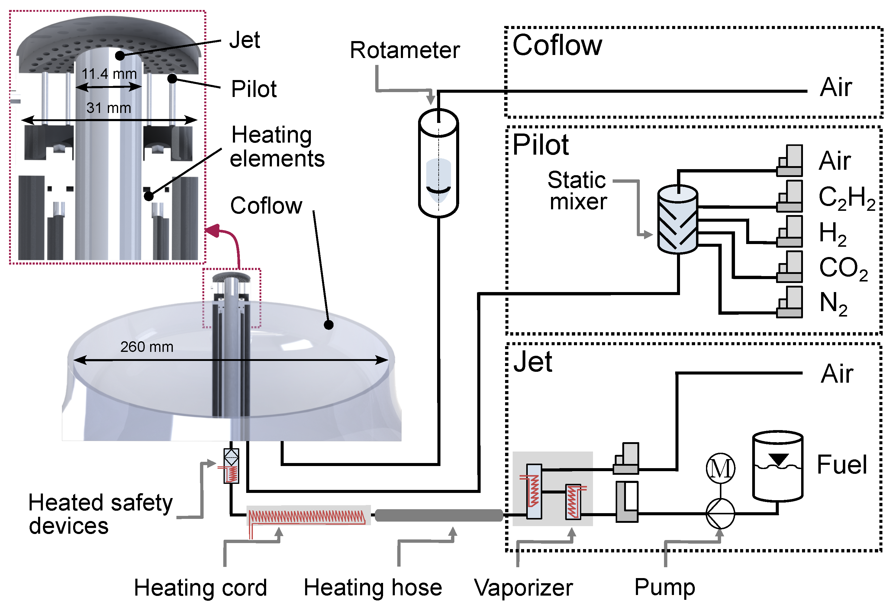
2.1. Temperature-Controlled Jet Burner

The measurements were carried out in a temperature-controlled jet burner (TCJB), designed to operate with pre-evaporated fuels. The jet burner has already been described in [30], so only the most important characteristics are summarized here. A sketch of the TCJB and the flow system is shown in Figure 1. A tube with an inner diameter of Dj = 11.4 mm and length of L = 500 mm resulted in a dimensionless tube length of L/D j ≈ 43, which resulted in a fully developed turbulent pipe flow. To avoid condensation of the pre-evaporated fuel at any point in the system, a continuous heat supply by heating elements with temperature control was implemented. The gas temperature was controlled at the nozzle outlet with an accuracy of ±1 K. A premixed pilot flame was utilized to stabilize the fuel-rich jet flame under turbulent conditions by an array of 144 individual laminar premixed Bunsen flames. The Bunsen flames are organized into four concentric rings with a diameter of 14 mm, 18 mm, 22 mm and 26.5 mm, each comprising 36 uniformly distributed orifices with diameters of 0.8 mm, 0.95 mm, 1.1 mm, and 1.2 mm. The premixed reactants of the pilot flame were composed of hydrogen ( H 2 ), acetylene (C2H2), CO2, nitrogen (N2), and air at ambient temperature to ensure the same equilibrium composition and enthalpy as the fuel mixture [31]. The volumetric concentrations of the components for the different operating conditions were varied such that the adiabatic flame temperature of the pilot flame was equal to jet fuel mixture operated at an equivalence ratio of ϕ = 0.7. An air co-flow with a bulk velocity of u b u l k = 0.3 m/s, generated by a contoured nozzle with 260 mm diameter, was used to ensure defined boundary conditions and to shield both flames from outside disturbances.
In a fuel supply system for liquid fuels, described in [30], a combined evaporation and gas heating system (ADrop DV4) with a matrix evaporation temperature of 523 K was employed. A Coriolis mass flow controller (Coriflow MFCs, Bronkhorst, Ruurlo, The Netherlands) was used for constant, pulsation-free delivery of the fuel mixture (zero stability of <±6 g/h). The vaporized fuel and heated air, as the carrier gas, were mixed in a static mixer with an outlet temperature of 498 K. Air and other gases for the pilot flame were individually controlled by calorimetric mass flow controllers (MFCs, Bronkhorst).
Table 1 summarizes six conditions investigated in this study using different fuel blends, denoted as cases 1–5. In case 1 (base case), a pure diesel surrogate was used. Due to the limited device temperatures in the system, the evaporation enthalpy and the capability to achieve high Reynolds numbers in the jet, a blend of n-dodecane (65 vol%), iso-octane (23.7 vol%) and m-xylene (11.3 vol%) was chosen. The main difference between the selected diesel surrogate and the IDEA reference fuel is the molecular structure of the aromatics. M-xylene has only one benzene ring in contrast to AMNL with two rings, resulting in a higher soot tendency at the same mixture fraction. However, in order not to approach the systems temperature limits, m-xylene was used, because its boiling point of 412 K is lower than that of AMNL (518 K).
The OME-blend (OME35) consisting of OME2 (0.5 vol%), OME3 (78.7 vol%), OME4 (19.8 vol%) and OME5 (0.4 vol%) (rest water, due to the hydrophilic characteristic) was added to the diesel surrogate in cases 2, 3, and 4 at increasing volumetric concentrations of 10 vol%, 30 vol%, and 50 vol%, while in case 4b, OME35 was replaced with OME4 at the same concentration. In case 5, the diesel surrogate was completely substituted by pure OME35 to allow a direct comparison of soot formation. All OMEn were purchased from ASG-Analytic, Neusäß, Germany.
The equivalence ratio for all jet flames was set to ϕ = 2.75 and the Reynolds number was Re = 12,000 at a constant nozzle outlet temperature of 498 K. Droplet formation is critical when studying condensable fuel using laser diagnostics because it affects signal detection. To check for possible condensation in the system and especially at the nozzle outlet, Mie scattering measurements were performed using a frequency doubled Nd:YAG laser at 532 nm. For this purpose, the evaporator was operated at the maximum possible mass flow rate from the diesel surrogate, since it has the highest enthalpy of evaporation and boiling temperature. No Mie scattering signals of droplets were detected directly at the nozzle outlet, ensuring droplet-free operation at all conditions.

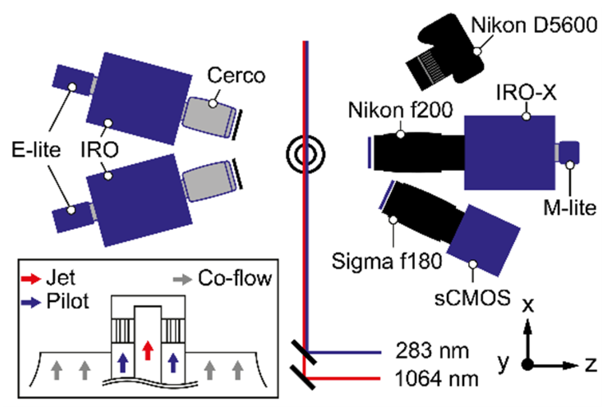
2.2. Simultaneous OH-LIF, PAH-LIF and LII Measurements

Figure 2 shows the experimental setup for the simultaneous laser-based multi-parameter measurements of turbulent flames in the TCJB burner. Laser-induced fluorescence was used to detect OH radicals and PAHs by using the same wavelength of 282.75 nm to excite the Q1(5) line of the OH A2 Σ ± X2 Π (1,0) band. The UV laser beam was generated by a frequency-doubled dye laser (Cobra Stretch, Sirah, Grevenbroich, Germany), pumped with a frequency-doubled Nd:YAG laser (Indi, Spectra Physics, Milpitas, CA, USA) at 532 nm and a repetition rate of 10 Hz. The dye laser was operated with rhodamine 6G dissolved in ethanol. Using a pump energy of approximately 230 mJ resulted in ∼4 mJ in the UV. The laser beam was directed to the probe volume via several beam shaping optics and a 45° dichroic mirror. A combination of cylindrical lenses formed the beam into a laser sheet with a height of 32 mm and a thickness of ∼250 µm (FWHM), with a laser fluence of about 0.028 J/cm2. The low laser fluence prevented the UV laser beam from generating LII signals. A beam splitter was applied to direct the laser sheet with a small portion of energy into a cuvette filled with a dilute mixture of coumarin in ethanol. The fluorescence signal in the cuvette was recorded by a CCD camera and used for beam profile correction. The OH fluorescence signal was detected with an image intensifier (IRO, LaVision, Göttingen, Germany) in combination with a CCD camera (Imager E-lite, LaVision) equipped with a UV lens (Sodern Cerco, f/2.8, f = 100 mm), a distance ring (+48 mm), and an interference filter with a central wavelength at 316 nm (band width ±5 nm, LC-HBP316/10, Laser Components, Olching, Germany).
Another detection system recorded the PAH-LIF signal, consisting of the identical components (camera, image intensifier, lens, and distance rings) as those used for OH-LIF. A long-pass filter with a cut-off wavelength of 325 nm (>90%, Edmund Optics, Barrington, NJ, USA) was chosen here to avoid crosstalk of OH-LIF signals in the PAH-LIF camera. Consequently, this filter allows the detection of molecules such as naphthalene, phenanthrene, pyrene, and fluoranthene. The distance to the probe volume for both camera systems was approximately 215 mm. Both detection systems were inclined with an angle of 11.5° to the y-axis. The projected pixel resolution was 47 µm per pixel for both LIF techniques.
Two-dimensional LII measurements were performed quasi simultaneously using an Nd:YAG laser (Spitlight 400, InnoLas, Krailling, Germany) at 1064 nm, with a repetition rate of 10 Hz and an output pulse energy of ∼360 mJ. The laser beam was formed into a thin sheet with a height of 30 mm and a thickness of ∼320 µm (FWHM). The spatial energy distribution within the laser sheet was examined by a beam profiling CMOS camera (DataRay, WinCamD, Redding, CA, USA) and turned out to be homogeneously distributed, with a plateau uniformity of 0.6. A mean laser fluence of 0.3 J/cm2 was used to ensure that the LII intensity obtained was barely dependent on the laser pulse energy [25]. A CMOS camera (M-lite, LaVision) combined with an intensifier (IRO-X with GaAsP photocathode, LaVision) was placed perpendicularly to the probe volume for collecting the LII signal. A Nikkor lens (f = 200 mm, f/5.6, Nikon, Tokyo, Japan) and a band-pass filter (450 nm ± 25 nm) were applied. The pixel resolution matched that for the LIF measurements (47 µm/pixel). For all intensifiers used and according to the manufacturer, the optical resolution was 55 µm.
The spatial overlap of the UV and infra-red (IR) laser sheets was carefully examined by a beam profiling camera (WinCamD, DataRay). All excitation and detection systems were temporally synchronized such that the IR laser was delayed by 85 ns to the UV laser pulses, excluding crosstalk between the LIF and the LII signal. To suppress signals from luminous flames, a gate of 80 ns was set for the OH-LIF measurements. The gate for the PAH-LIF was 70 ns with a delay of 15 ns relative to the OH-LIF gate to minimize crosstalk to the fast decaying OH signal. Moreover, the sensitivity of spectrally broad PAH-LIF emission with regards to the excitation wavelength was evaluated by tuning the laser ±0.5 nm from the central wavelength. In contrast to the high wavelength selectivity of OH-LIF signals, no significant influences were observed in the PAH-LIF intensity. For the LII measurements, a gate of 150 ns with a gain of 87% was chosen.
For all laser-based measurements and for statistical analysis, 2000 images were recorded for each individual field of view (FOV). The background intensities were subtracted from the instantaneous images, which were used for time averaging. In addition, the laser intensity fluctuations for both PLIF signals were corrected for local laser intensity variations by means of imaging a homogeneously filled dye cuvette. The corresponding instantaneous images from the OH signal were then subtracted from the PAH single-shots in order to mask out contributions of OH in the PAH recordings since the OH-LIF emission spectrally slightly overlapped with the PAH detection.

2.3. Chemiluminescence Imaging

For the visualization of the macroscopic flame structures, a single-lens reflex camera (DSLR, D5600, Nikon) was used, as shown in Figure 2, to record spectrally broadband photographs of the turbulent flames. Photographs were captured with an exposure time of 2 ms (ISO 100) and a Nikkor lens (f = 50 mm, Nikon). Additionally, chemiluminescence (CL) imaging of electronically excited C2* was used as a common marker for the location of fuel-rich regions. The strong emission peaks of the Swan band near 513 nm and 517 nm were detected by a scientific CMOS camera (Imager sCMOS, LaVision) combined with a lens (f = 50 mm) and a band-pass filter (515 ± 10 nm, Edmund Optics). The camera was operated with an exposure time of 25 ms and the signal was triggered simultaneously, with OH-PLIF measurements at 10 Hz. The FOV was ∼562 × 474 mm² (2536 × 2100 pixels), with a projected pixel resolution of 220 µm. This camera system for line-of-sight measurements was placed beside the LII detection system, with an angle of ∼30° inclined to the y-axis. For each condition listed in Table 1, 500 C2* images were recorded. Taking advantage of the rotational symmetry of the flame, the C2* luminescence images were transformed using the Abel-inversion.

3. Results and Discussion

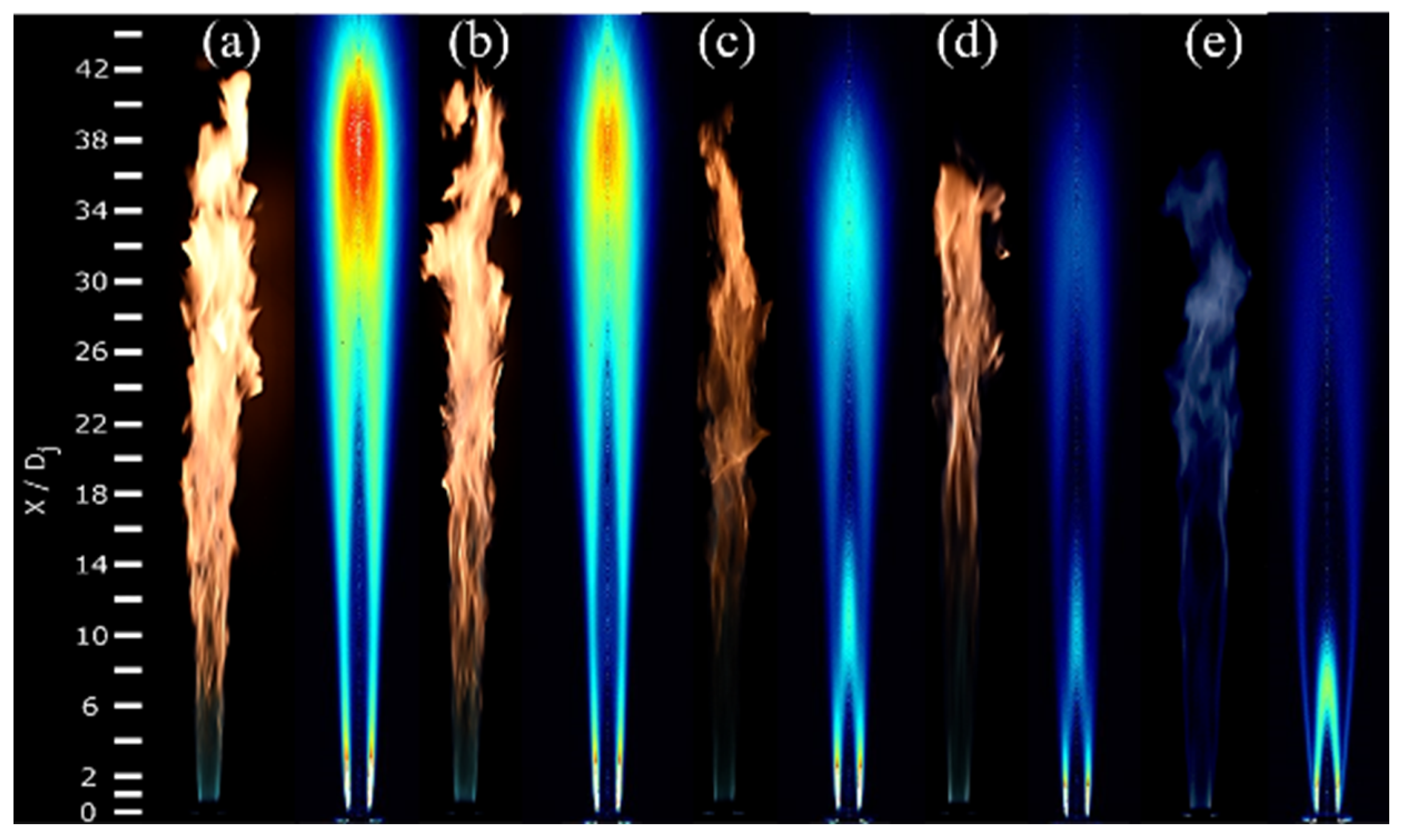
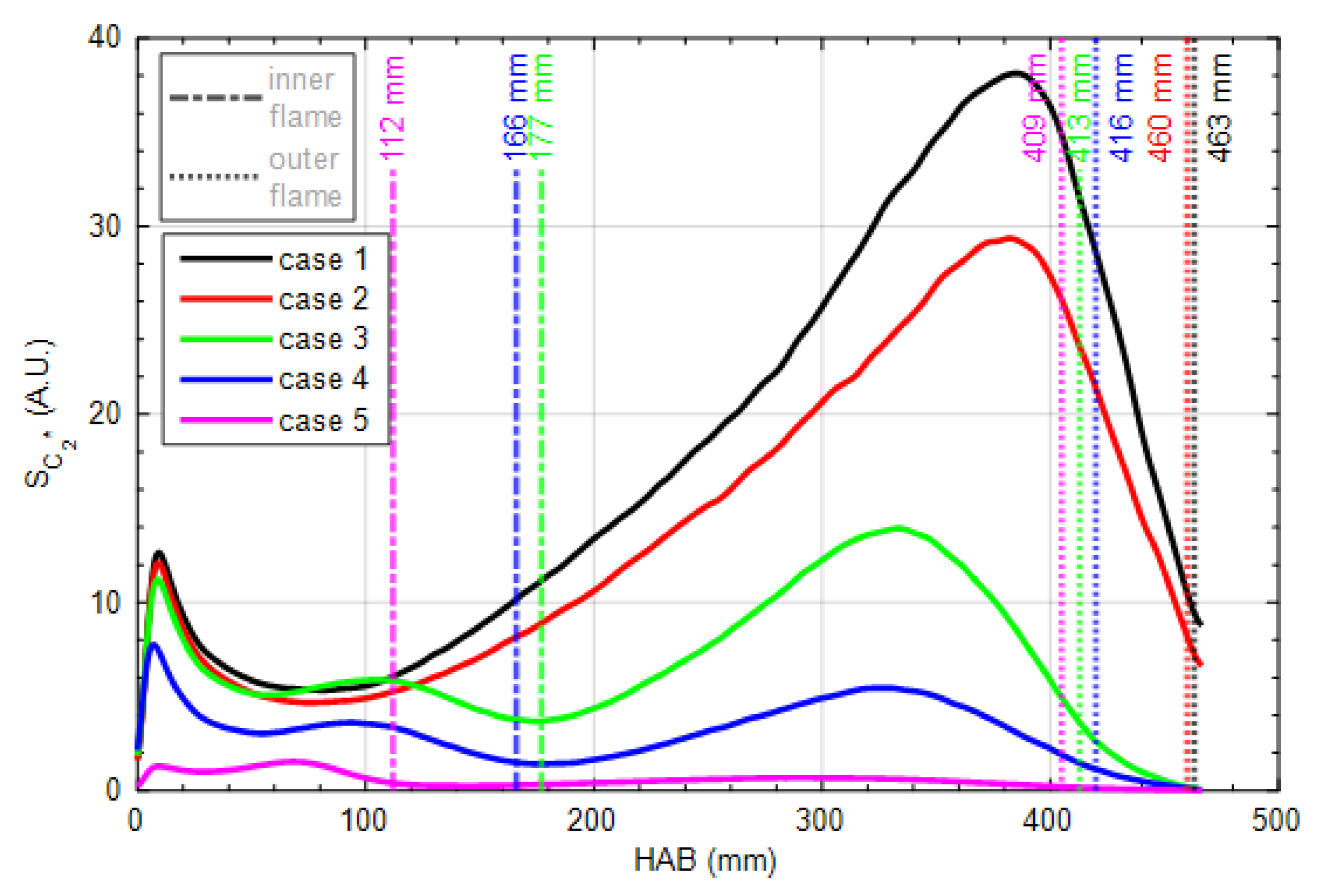
3.1. Global Flame Structure and Flame Length

In the present study, five different turbulent diesel surrogate flames with varying OMEn blending ratios were investigated (see Table 1). In Figure 3, DLSR photographs and Abel-inverted CL images of the electronically excited C2* molecule of the individual flames are compared side by side [32]. To allow direct comparison of image intensities between the different operating conditions, the lens aperture and exposure time of the respective cameras were kept constant. Soot formation can be identified from the yellowish color in DLSR photographs, whereas soot precursors such as C2H2 and C2H4 are correlated to the C2* emission. Due to the shorter exposure time, turbulent structures are visible only in the color photographs. Comparing the color photographs directly to each other, it is noticeable that the visual soot formation is evidently reduced with the addition of OME35. In case 5, the bluish color in the flame photograph indicates that soot is not produced at significant amounts in the pure OME35 flame. Accordingly, C2* intensities progressively reduce as more OME35 is added to the diesel surrogate, indicating a strong suppression of soot precursors. Case 1 and case 2 reveal typical non-premixed flame structures due to the high equivalence ratio. In addition, an inner flame zone, marked by C2*, is gradually formed with the admixture of more than 30vol% OME35. The length and intensity of the inner reaction zone are reduced with increasing OME35 concentrations. It has to be noted that C2* signal intensities were boosted by a factor of five in case 5.
For a better visualization of the global flame structure, an Abel-inversion was performed to create a cross-sectional view of the flame. This technique is applicable to the time-averaged flame, given its rotational symmetry. To further quantify the global flame structure, the lengths of the inner and outer flames are characterized based on the corresponding Abel-inverted CL images of C2* for the cases shown in Figure 3. As shown in Figure 4, the outer flame lengths are extracted from the C2* images by determining the axial position where the respective radially integrated intensity drops to 25% of its maximum intensity along the axial direction (indicated by vertical dotted lines), as proposed in [30,33], using CH radical imaging and flame luminosity measurements. This procedure applies to all cases.
Similarly, if an inner flame is visible, as in case 3–5, the inner flame length is determined using the same 25% criterion. However, for the inner flame, the analysis selectively excludes the outer flame region by focusing only on the inner peak of the intensity curve. The axial position where this inner intensity falls to 25% of its peak value is then marked by a dashed-dotted vertical line, which denotes the inner flame length. This approach ensures that both inner and outer flame lengths are consistently and accurately quantified, allowing for a clear comparison between different cases.
It can be observed that case 1 and case 2 have a similar outer flame length of about 463 mm, which is the largest of all cases. As more OME35 is added into the fuel mixture, the outer flame length decreases, which is related to the higher burning velocity of OME3 [34]. This observation in flame length shows that OME35, which primarily contains OME3, has a higher burning velocity compared to the surrogate. It is clearly seen that cases 1 and 2 show no visible inner flame, indicating lower chemical reactivity and longer ignition delay times. In contrast, cases 3, 4, and 5 exhibit a visible inner flame, which leads to a significantly shorter outer flame length. This suggests that the faster burning velocity of OME35 and the increased reactivity in the inner flame region significantly influence the stability and length of the outer flame. The interaction between the inner and outer flames may also point to a more complex heat release dynamic, causing the outer flame to decay more rapidly.
The peak C2* intensity decreases due to the absence of C-C bonds in the molecular structure of OMEn. The observed decrease in C2* emission intensity with increasing OME35 content is a significant finding that highlights the influence of molecular structure on combustion emissions. OME35, characterized by the absence of C-C bonds, misses the typical hydrocarbon pathways that lead to the formation of C2* species, resulting in a lower emission intensity. Above 30 vol% OME35, an inner flame structure appears. This effect is most pronounced in case 5, where the C2* emission is significantly reduced due to the scarcity of larger hydrocarbons that are precursors for C2* formation. The molecular structure of OMEn, which is rich in oxygen but deficient in C-C bonds, suppresses the formation of hydrocarbon intermediates that contribute to soot and C2* production. The oxygenated fuel increases the oxygen proportion in the fuel compared to the diesel surrogate without any fuel-bounded oxygen and enhances its chemical reactivity at low temperatures, leading to short ignition delay times. This is also one of the reasons for the shorter outer flame length, because surrogates are partially oxidized, e.g., by OMEn decomposition products methoxy radicals and formaldehyde, in the inner flame zone. This suppression suggests that OMEn supports a cleaner combustion process with reduced soot formation, making it a promising candidate for environmentally friendly combustion applications. The reduced C2* signal can also be linked to the lower availability of carbon fragments, which are critical for the formation of soot precursors, further supporting the potential of OME35 to minimize particulate emissions. Due to the abundance of oxygen-containing intermediates, formation of hydrocarbons larger than C2 is hindered in pure OMEn, and the weak C2* signal observed in case 5 is probably attributed to C1 recombination reactions [35].

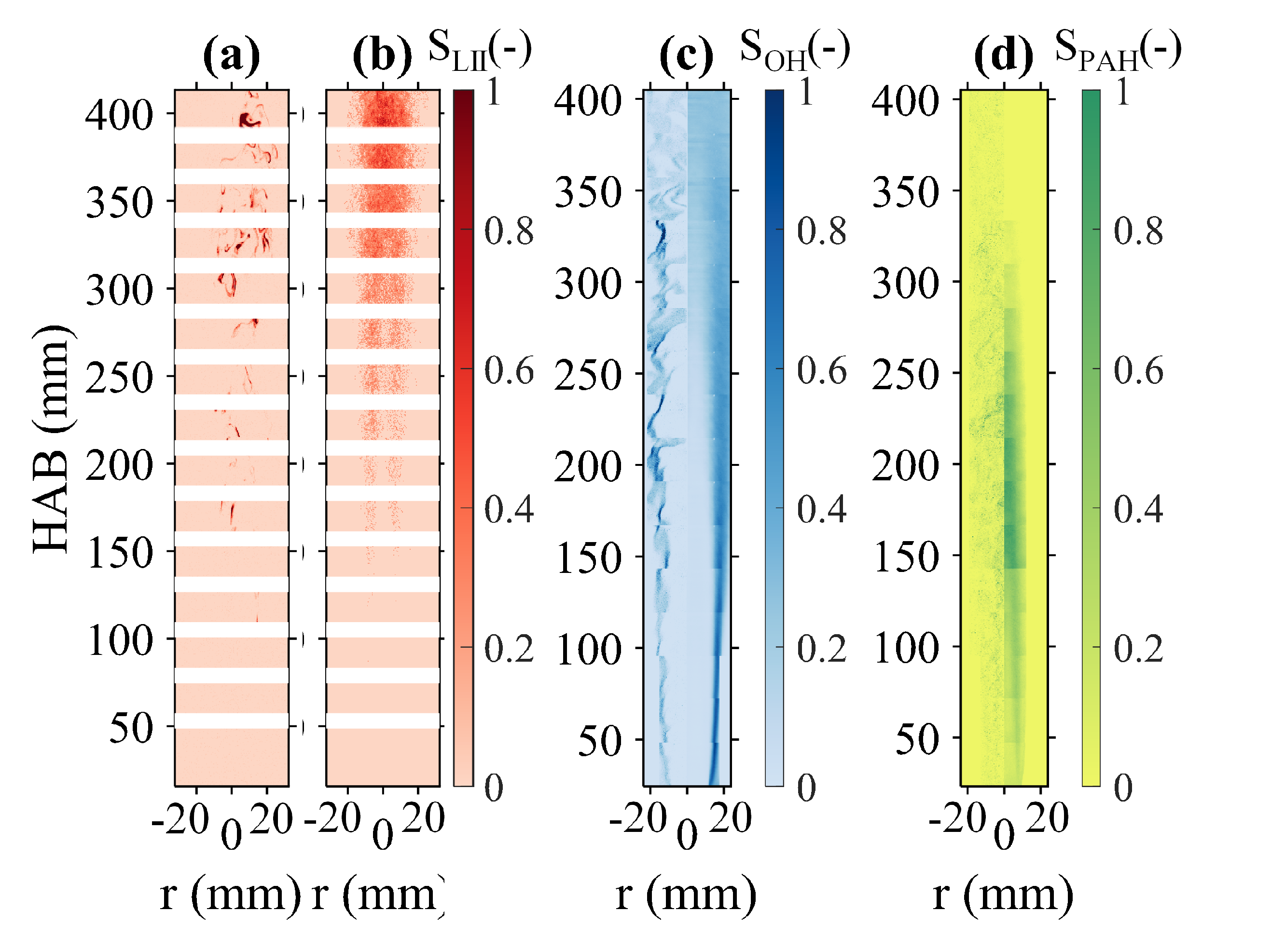
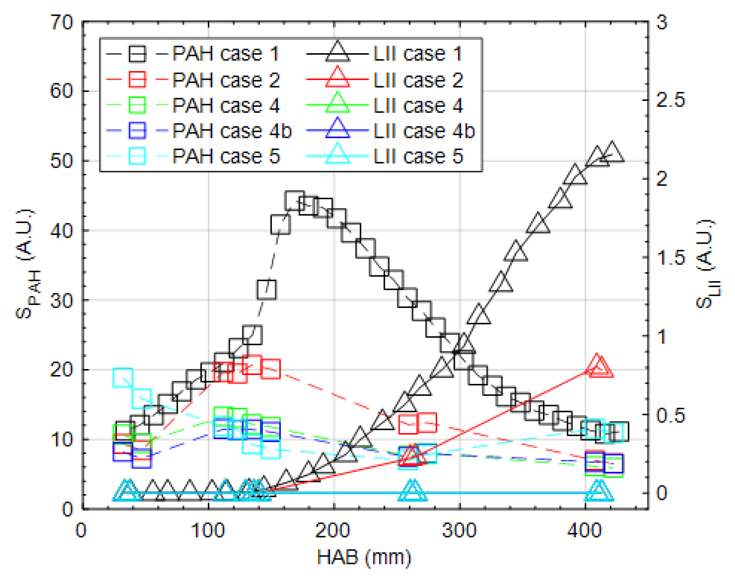
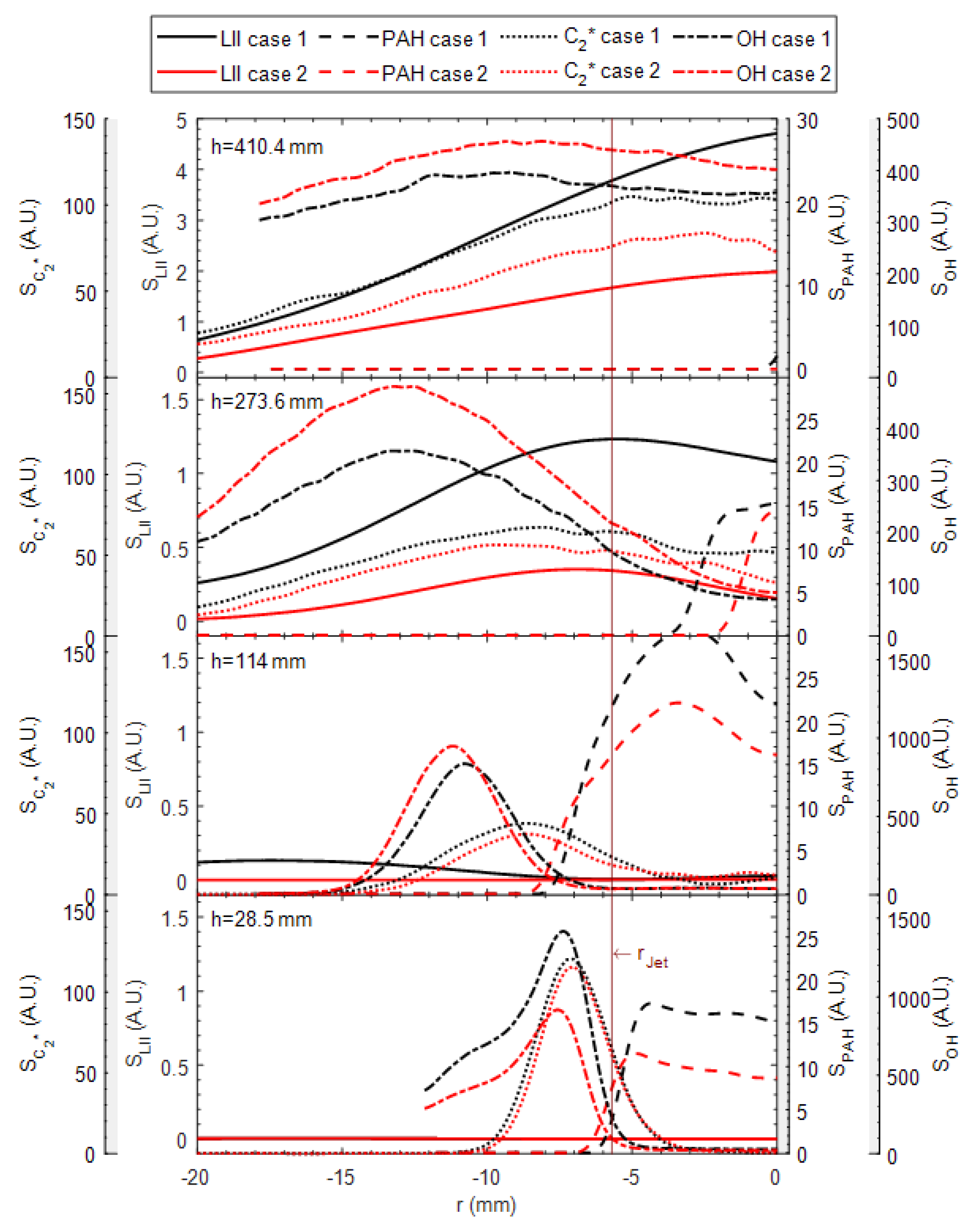
3.2. OH, PAH and Soot Structures

Figure 5 shows a side-by-side comparison of the normalized instantaneous (left) and time-averaged (right) recordings of LII, OH-LIF, and PAH-LIF over the entire flame height for case 1, starting from a height above the burner (HAB) of about 25 mm. Note that the simultaneous measurements were carried out over the entire flame length for case 1, but only at several selected FOVs for cases 2–5. The selection includes standardized fixed axial positions of the FOVs for all cases and individual FOVs corresponding to the onset of soot formation. In Figure 5a the instantaneous and in Figure 5b the time-averaged LII images show the spatial distribution of soot particles. Inspecting the instantaneous image, the soot signal is limited to small regions due to the high turbulence and the resulting fluctuation of the flame. Downstream, the signal increases but continues to fluctuate despite the formation of larger soot areas. The time-averaged soot distribution indicates the soot onset at about HAB = 135 mm, taking into account that the estimated detection limit for soot is ∼0.03 ppm [26].
Instantaneous and time-averaged OH-LIF images are shown with the corresponding PAH-LIF images in Figure 5c,d, to investigate the spatial correlation between PAH and OH zones. Due to the turbulent flow and associated out-of-plane fluctuations of the 2D measurements, 2000 instantaneous images were recorded, ensuring a converged mean in the measurement plane.
In the single-shot OH images, typical turbulent flame structures are recognizable. High intensity gradients at upstream positions are associated with the exhaust gas of the pilot flame; however, an overall diffusion flame structure is expected here as the fuel mixture is outside the flammability limits. Downstream, a spatial fluctuation of the reaction zone position, and highly stretched and curved reaction zones are observed due to the turbulent shear flow of the jet.
The time-averaged image shows that the PAHs primarily appear in the central region, enclosed by the reaction zone marked by OH. The PAH structures depicted in Figure 5d contain multiple PAH molecules with varying numbers of rings due to the broadband emission spectrum detected. The high temperature in the central fuel-rich region of the flame favors the conversion of PAHs with few rings into larger PAHs along the flame height. Therefore, PAH signals increase along the vertical direction as they form, and then decrease downstream, which is due to the expected conversion of PAHs of smaller classes into larger PAHs and further into soot by particle inception and thermochemical processes with increasing residence time [26].
Figure 6 presents selected representative superimposed instantaneous images for OH, PAH, and the qualitative soot distribution for five selected cases at two different FOVs (250–280 mm (FOV 2) and 400–430 mm (FOV 1)). All signals are normalized to their respective maximum. Differences in absolute intensities are discussed in the context of Figure 7. In FOV 1 (top row), images show independently of the fuel that the turbulent OH structures dominate. The absolute PAH intensity decreases by admixing more OMEn. Where no OH radicals are observed within the flame structures, soot structures predominantly form in the pure diesel surrogate flame at FOV 1, i.e., case 1 (Figure 6a), with a low PAH content in the adjacent area. The soot distributions spatially align with the OH structures despite high turbulence within the flame. The weak PAH structures spatially correlate with the OH and soot signal, but occur at lower locations with less soot present, e.g., in all cases of FOV 2 (Figure 6f–j). With increasing concentrations of OMEn, the soot intensity decreases and no obvious PAHs are detected in FOV 1. Comparing case 4 (Figure 6c) with case 4b (Figure 6d), the appearance of the instantaneous soot structures with 50 vol%. OME35 appear with a slightly larger area than with 50 vol% OME4 (also shows statistically higher soot intensities, as discussed in Figure 7). In general, the separation between the soot region and flame zone, as marked by OH, enlarges with increasing OMEn. Less soot formation in case 4b compared to case 4 can be expected because OME4 has higher oxygenation due to the longer molecular chain. No soot occurs with the pure OME35, as shown in case 5 (Figure 6e). PAHs are homogeneously distributed at rather low concentrations in pure OME35 flames. This indicates that PAHs are formed in OMEn flames but are oxidized at high temperatures without any indication of soot formation, in accordance to [36].
Comparing the FOV 1 with FOV 2 at a lower axial height, it is noticeable that considerably more PAH structures are present in the diesel surrogate flames of case 1 (Figure 6f). Soot is also present at this height and spatially correlates with the OH and PAH signal. It is also noticeable that local variations of the individual signal intensities are present due to turbulent fluctuations in the shear layer, which is in difference to laminar flames with spatially well-aligned layers of OH, soot, and PAHs [37]. This observation suggests that the PAHs downstream of the soot region might lead to soot formation due to a turbulence-induced vortex orientation, e.g., in case 1 (Figure 6f) and cas 2 (Figure 6g), in which the soot region is enclosed by PAHs. Due to the fact that only the emissions of large PAHs are captured, PAH LIF intensities appear weaker (see Figure 7) since multi-ring PAHs are formed at this height. This reduces the number of PAH molecules, which is thus noticed by a weaker signal. For case 2, with an admixture of 10 vol% of OME35 to the diesel surrogate (Figure 6g), it is observed that the soot approaches the flame zone more closely than in the case of the pure diesel surrogate, but soot does not directly contact the OH layer in any case. Already with an admixture of 50vol% OME35, case 4 (Figure 6h) and 50 vol% OME4, case 4b (Figure 6i), no soot is detectable in this FOV. The PAH signal is stronger in case 1 than in case 2 and case 4, whereas soot has not yet formed due to the short residence time (see Figure 7). In case 5, as expected, no soot or PAHs can be detected. Here, the very weak PAH signal is homogeneously distributed within the fuel-rich zone.
Figure 7 shows the axial PAH (squares) and soot (triangles) signals radially integrated and averaged from 2000 images to characterize the different cases 1, 2, 4, 4b and 5. For case 1, the entire flame was recorded starting from a HAB of 25 mm to 430 mm. For cases 2, 4, 4b and 5, as described previously, only selected FOVs were recorded. Case 1 shows a non-linear increase of the PAH signal up to a HAB of ∼160 mm. Noticeable here is an already remarkable PAH level at HAB = 25 mm, which is probably attributed to the fact that the diesel surrogate contains PAHs due to the aromatic m-xylene and that diesel surrogates generate PAHs with smaller rings at lower HABs [11]. The averaged soot signal starts at a HAB of approx. 150 mm, thus shortly before the PAH signal reaches its maximum. Downstream from a HAB of >400 mm, the PAH signal decreases and reduces to a similar intensity level as at the burner exit. Compared to the PAH signal, the soot signal increases steadily up to this HAB. Due to the low intensity and small-scale structures in the instantaneous soot signals, the onset of soot might be slightly underestimated in the averaged image. In some images of the instantaneous recordings, it is noticeable that the appearance of soot at lower HABs is possible.
As expected from the single-shot comparison shown in Figure 6, the trends of PAH intensity of case 2, 4 and 4b are similar, but reveal significantly lower signal intensities compared to case 1. Importantly, the height of the maximum PAH intensity decreases with increasing OME admixture, which is consistent with the inner flame lengths shown in Figure 4. The reduction of intensity downstream is due to oxidation and the PAH long-pass filter, as discussed previously. Already with an admixture of 10vol% OME35 (case 2), a significant reduction of soot is apparent. By adding more OME35 or OME4 to the diesel surrogate, the integrated averaged soot signal is reduced even further.
For a more detailed insight, the averaged radial profiles of the LII, PAH, OH-LIF and C2* signal are shown at four different heights above the burner for case 1 and case 2 in Figure 8. The radius of the jet is also marked. The results clearly indicate that at a HAB of 28.5 mm, the OH-LIF and PAH-LIF signals are spatially separated from each other, and all signals of case 1 are higher than those from case 2. Higher PAH and C2* signals are consistent with the higher amount of precursors present in the fuel of case 1. The location of C2* peak is, as expected, located close to the steepest gradient of OH at the fuel rich side, which can be observed at a HAB of 114 mm. Furthermore, the PAH-signal increases until a HAB of 114 mm, where still almost no soot is detectable, and decreases when soot occurs further downstream. It is also evident that the behavior of C2* is different downstream compared to the burner exit, where it initially has a strong symmetrical signal, decreases like the OH signal, and increases again with the appearance of soot in the flame. This reinforces the statement about the increased occurrence of carbon in soot formation [38]. Furthermore, it is evident that the surrogate flame in case 1 under the same flow conditions exhibits a slightly narrower width compared to the fuel mixture in case 2, as observed in the OH profiles.

4. Conclusions

In this study, diesel surrogates with different proportions of OME are pre-evaporated to qualitatively determine characteristics such as the flame structures, soot precursors and soot tendency under turbulent conditions. In addition to chemiluminescence images of C2* and DSLR colour images to study the turbulent jet flame, the laser diagnostic measurement techniques OH-LIF, PAH-LIF and 2D-LII are used to investigate these characteristics.
It is found that by adding OME, the flame length is reduced and an inner flame zone is formed at a constant jet equivalence ratio of 2.75, which can be attributed to the fuel-bounded oxygen and increased chemical reactivity.
By combining quasi-simultaneously LIF and LII measurement techniques, it is shown that in the instantaneous images within the HAB < 415 mm, pure diesel surrogate reveals stronger soot signals than the admixtures of OME and no soot is detectable for operation with pure OME35. At a lower HAB of 265 mm, the soot signal is significantly lower (compared to the soot signal downstream) in cases 1 and 2; whereas in the other cases, soot is non-existent. PAHs are clearly present in all cases.
Despite high turbulence levels causing reaction zone wrinkling, soot, PAH and OH have a structural correlation and are thus interdependent. This interdependency becomes obvious when comparing the integrated mean intensities of PAH-LIF and the LII signal, as the soot signal in the diesel surrogate flame starts to rise axially just upstream of the PAH maximum. A similar trend is also observed in the other cases examined, as well as in the radial profiles of case 1 and case 2, which also include the correlation between soot, precursors, OH- and C2*-signal.
This study provides new data for turbulent jet flames operated with pre-vaporized diesel surrogates and varying admixtures of OME as needed for the validation of soot modeling for OMEn-containing combustion systems.

Author Contributions

Conceptualization, S.W., D.G., A.D. and B.B.; methodology, S.W.; software, S.W.; validation, S.W., T.L. and B.B.; formal analysis, S.W.; investigation, S.W.; resources, D.G., A.D. and B.B.; data curation, S.W.; writing—original draft preparation, S.W.; writing—review and editing, T.L., D.G., A.D. and B.B.; visualization, S.W.; supervision, D.G., A.D. and B.B.; project administration, B.B.; funding acquisition, A.D. and B.B. All authors have read and agreed to the published version of the manuscript.

Funding

The authors gratefully acknowledge the support of the German Federal Ministry of Education and Research (BMBF) within the NAMOSYN project “Sustainable Mobility through Synthetic Fuels” (grant no. 03SF0566R1) and the project “Interference-resistant Raman spectrometer”, Germany (PN 514177753).

Data Availability Statement

Data can be provided upon reasonable request.

Conflicts of Interest

The authors declare no conflicts of interest.

Abbreviations

The following abbreviations are used in this manuscript:
AMNL α -methylnaphthalene
A.U.Arbitrary Units
C2*carbon radicals
CCDcharge-coupled device
CLchemiluminescence
CMOScomplementary metal-oxide-semiconductor
DSLRdigital single-lens reflex camera
FOVfield of view
FWHMfull width at half maximum
GaAsPgallium arsenide phosphide
HABheight above the burner
IRinfra-red
IROintensified relay optics
JP-8Jet Propellant 8
LIIlaser-induced incandescence
MFCmass flow controller
Nd:YAGneodymium-doped yttrium aluminum garnet
OHhydroxyl radical
OH-LIFplanar laser-induced fluorescence of OH
OMEpoly(oxymethylene) dimethyl ether
PAHpolycyclic aromatic hydrocarbon
PAH-LIF  planar laser-induced fluorescence of PAH
PLIF  planar laser-induced fluorescence
TCJB  temperature-controlled jet burner
UV  ultra-violet

References

  1. Burger, J.; Siegert, M.; Ströfer, E.; Hasse, H. Poly(oxymethylene) dimethyl ethers as components of tailored diesel fuel: Properties, synthesis and purification concepts. Fuel 2010, 89, 3315–3319. [Google Scholar] [CrossRef]
  2. Lahaye, J. Soot in Combustion Systems and Its Toxic Properties; Volume 7, Nato Conference Ser; Springer: New York, NY, USA, 1983. [Google Scholar]
  3. de Ras, K.; Kusenberg, M.; Thybaut, J.W.; van Geem, K.M. Unraveling the carbene chemistry of oxymethylene ethers: Experimental investigation and kinetic modeling of the high-temperature pyrolysis of OME-2. Proc. Combust. Inst. 2023, 39, 125–133. [Google Scholar] [CrossRef]
  4. Svensson, K.I.; Richards, M.J.; Mackrory, A.J.; Tree, D.R. Fuel Composition and Molecular Structure Effects on Soot Formation in Direct-Injection Flames Under Diesel Engine Conditions. SAE Trans. 2005, 114, 594–604. [Google Scholar] [CrossRef]
  5. Westbrook, C.K.; Pitz, W.J.; Curran, H.J. Chemical kinetic modeling study of the effects of oxygenated hydrocarbons on soot emissions from diesel engines. J. Phys. Chem. A 2006, 110, 6912–6922. [Google Scholar] [CrossRef] [PubMed]
  6. Zhu, R.; Wang, X.; Miao, H.; Yang, X.; Huang, Z. Effect of dimethoxy-methane and exhaust gas recirculation on combustion and emission characteristics of a direct injection diesel engine. Fuel 2011, 90, 1731–1737. [Google Scholar] [CrossRef]
  7. Pellegrini, L.; Marchionna, M.; Patrini, R.; Florio, S. Emission Performance of Neat and Blended Polyoxymethylene Dimethyl Ethers in an Old Light-Duty Diesel Car; SAE Technical Paper; SAE: Warrendale, PA, USA, 2013. [Google Scholar] [CrossRef]
  8. Liu, H.y.; Wang, Z.; Wang, J.X. Performance, Combustion and Emission Characteristics of Polyoxymethylene Dimethyl Ethers (PODE 3-4 )/ Wide Distillation Fuel (WDF) Blends in Premixed Low Temperature Combustion (LTC). SAE Int. J. Fuels Lubr. 2015, 8, 298–306. [Google Scholar] [CrossRef]
  9. Pitsch, H.; Goeb, D.; Cai, L.; Willems, W. Potential of oxymethylene ethers as renewable diesel substitute. PRogress Energy Combust. Sci. 2024, 104, 101173. [Google Scholar] [CrossRef]
  10. Karataş, A.E.; Gülder, Ö.L. Soot formation in high pressure laminar diffusion flames. Prog. Energy Combust. Sci. 2012, 38, 818–845. [Google Scholar] [CrossRef]
  11. Mercier, X.; Carrivain, O.; Irimiea, C.; Faccinetto, A.; Therssen, E. Dimers of polycyclic aromatic hydrocarbons: The missing pieces in the soot formation process. Phys. Chem. Chem. Phys. PCCP 2019, 21, 8282–8294. [Google Scholar] [CrossRef]
  12. Bejaoui, S.; Lemaire, R.; Therssen, E. Analysis of Laser-Induced Fluorescence Spectra Obtained in Spray Flames of Diesel and Rapeseed Methyl Ester Using the Multiple-Excitation Wavelength Laser-Induced Incandescence Technique with IR, UV, and Visible Excitations. Combust. Sci. Technol. 2015, 187, 906–924. [Google Scholar] [CrossRef]
  13. Vander Wal, R.L.; Jensen, K.A.; Choi, M.Y. Simultaneous laser-induced emission of soot and polycyclic aromatic hydrocarbons within a gas-jet diffusion flame. Combust. Flame 1997, 109, 399–414. [Google Scholar] [CrossRef]
  14. Schulz, C.; Kock, B.F.; Hofmann, M.; Michelsen, H.; Will, S.; Bougie, B.; Suntz, R.; Smallwood, G. Laser-induced incandescence: Recent trends and current questions. Appl. Phys. B 2006, 83, 333–354. [Google Scholar] [CrossRef]
  15. Gaydon, A.G. The Spectroscopy of Flames; Springer: Dordrecht, The Netherlands, 1974. [Google Scholar] [CrossRef]
  16. Aye, M.M.; Beeckmann, J.; Vanegas, A.; Peters, N.; Pitsch, H. Experimental Investigation of Diesel and Surrogate Fuels: Spray and Ignition Behavior; SAE Technical Paper Series; SAE: Warrendale, PA, USA, 2011. [Google Scholar] [CrossRef]
  17. Pei, Y.; Mehl, M.; Liu, W.; Lu, T.; Pitz, W.J.; Som, S. A Multicomponent Blend as a Diesel Fuel Surrogate for Compression Ignition Engine Applications. J. Eng. Gas Turbines Power 2015, 137, 192. [Google Scholar] [CrossRef]
  18. Mueller, C.J.; Cannella, W.J.; Bays, J.T.; Bruno, T.J.; DeFabio, K.; Dettman, H.D.; Gieleciak, R.M.; Huber, M.L.; Kweon, C.B.; McConnell, S.S.; et al. Diesel Surrogate Fuels for Engine Testing and Chemical-Kinetic Modeling: Compositions and Properties. Energy Fuels 2016, 30, 1445–1461. [Google Scholar] [CrossRef]
  19. Weber, J.; Won, H.W.; Peters, N. Experimental Validation of a Surrogate Fuel for Diesel: Spray and Ignition Behavior; SAE Tehnical Paper; SAE: Warrendale, PA, USA, 2011. [Google Scholar] [CrossRef]
  20. Farrell, J.T.; Cernansky, N.P.; Dryer, F.L.; Law, C.K.; Friend, D.G.; Hergart, C.A.; McDavid, R.M.; Patel, A.K.; Mueller, C.J.; Pitsch, H. Development of an Experimental Database and Kinetic Models for Surrogate Diesel Fuels; SAE Technical Paper; SAE: Warrendale, PA, USA, 2007. [Google Scholar] [CrossRef]
  21. Mahmoud, S.M.; Nathan, G.J.; Alwahabi, Z.T.; Sun, Z.W.; Medwell, P.R.; Dally, B.B. The effect of exit Reynolds number on soot volume fraction in turbulent non-premixed jet flames. Combust. Flame 2018, 187, 42–51. [Google Scholar] [CrossRef]
  22. Bouvier, M.; Cabot, G.; Yon, J.; Grisch, F. On the use of PIV, LII, PAH-PLIF and OH-PLIF for the study of soot formation and flame structure in a swirl stratified premixed ethylene/air flame. Proc. Combust. Inst. 2021, 38, 1851–1858. [Google Scholar] [CrossRef]
  23. Köhler, M.; Geigle, K.P.; Blacha, T.; Gerlinger, P.; Meier, W. Experimental characterization and numerical simulation of a sooting lifted turbulent jet diffusion flame. Combust. Flame 2012, 159, 2620–2635. [Google Scholar] [CrossRef]
  24. Geigle, K.P.; O’Loughlin, W.; Hadef, R.; Meier, W. Visualization of soot inception in turbulent pressurized flames by simultaneous measurement of laser-induced fluorescence of polycyclic aromatic hydrocarbons and laser-induced incandescence, and correlation to OH distributions. Appl. Phys. B 2015, 119, 717–730. [Google Scholar] [CrossRef]
  25. Lemaire, R.; Faccinetto, A.; Therssen, E.; Ziskind, M.; Focsa, C.; Desgroux, P. Experimental comparison of soot formation in turbulent flames of Diesel and surrogate Diesel fuels. Proc. Combust. Inst. 2009, 32, 737–744. [Google Scholar] [CrossRef]
  26. Wang, Y.; Jain, A.; Schweizer, C.; Kulatilaka, W.D. OH, PAH, and sooting imaging in piloted liquid-spray flames of diesel and diesel surrogate. Combust. Flame 2021, 231, 111479. [Google Scholar] [CrossRef]
  27. Zhang, J.; Shaddix, C.R.; Schefer, R.W. Design of “model-friendly” turbulent non-premixed jet burners for C2+ hydrocarbon fuels. Rev. Sci. Instrum. 2011, 82, 074101. [Google Scholar] [CrossRef] [PubMed]
  28. de Andrade Oliveira, M.H.; Olofsson, N.E.; Johnsson, J.; Bladh, H.; Lantz, A.; Li, B.; Li, Z.S.; Aldén, M.; Bengtsson, P.E.; Luijten, C.; et al. Soot, PAH and OH measurements in vaporized liquid fuel flames. Fuel 2013, 112, 145–152. [Google Scholar] [CrossRef]
  29. Kruse, S.; Medwell, P.; Davidovic, M.; Sun, Z.; Ye, J.; Pitsch, H.; Dally, B.B. The effect of fuel composition and Reynolds number on soot formation processes in turbulent non-premixed toluene jet flames. Proc. Combust. Inst. 2021, 38, 1395–1402. [Google Scholar] [CrossRef]
  30. Trabold, J.; Hartl, S.; Walther, S.; Johchi, A.; Dreizler, A.; Geyer, D. Fuel Effects in Turbulent Premixed Pre-vaporised Alcohol/Air Jet Flames. Flow Turbul. Combust. 2021, 106, 547–573. [Google Scholar] [CrossRef]
  31. Schneider, C.; Dreizler, A.; Janicka, J.; Hassel, E.P. Flow field measurements of stable and locally extinguishing hydrocarbon-fuelled jet flames. Combust. Flame 2003, 135, 185–190. [Google Scholar] [CrossRef]
  32. Pretzier, G. A New Method for Numerical Abel-Inversion. Z. für Naturforschung A 1991, 46, 639–641. [Google Scholar] [CrossRef]
  33. Carbone, F.; Smolke, J.L.; Fincham, A.M.; Egolfopoulos, F.N. Comparative behavior of piloted turbulent premixed jet flames of C 1 C 8 hydrocarbons. Combust. Flame 2017, 180, 88–101. [Google Scholar] [CrossRef]
  34. Sun, W.; Wang, G.; Li, S.; Zhang, R.; Yang, B.; Yang, J.; Li, Y.; Westbrook, C.K.; Law, C.K. Speciation and the laminar burning velocities of poly(oxymethylene) dimethyl ether 3 (POMDME3) flames: An experimental and modeling study. Proc. Combust. Inst. 2017, 36, 1269–1278. [Google Scholar] [CrossRef]
  35. Tan, Y.R.; Botero, M.L.; Sheng, Y.; Dreyer, J.A.; Xu, R.; Yang, W.; Kraft, M. Sooting characteristics of polyoxymethylene dimethyl ether blends with diesel in a diffusion flame. Fuel 2018, 224, 499–506. [Google Scholar] [CrossRef]
  36. Singh, P.; Hui, X.; Sung, C.J. Soot formation in non-premixed counterflow flames of butane and butanol isomers. Combust. Flame 2016, 164, 167–182. [Google Scholar] [CrossRef]
  37. Mulla, I.A.; Renou, B. Simultaneous imaging of soot volume fraction, PAH, and OH in a turbulent n-heptane spray flame. Combust. Flame 2019, 209, 452–466. [Google Scholar] [CrossRef]
  38. Valencia, S.; Ruiz, S.; Manrique, J.; Celis, C.; Da Figueira Silva, L.F. Soot modeling in turbulent diffusion flames: Review and prospects. J. Braz. Soc. Mech. Sci. Eng. 2021, 43, 219. [Google Scholar] [CrossRef]
Figure 1. Schematic view of the burner and the flow system.
Fluids 09 00210 g001
Figure 2. Experimental setup of multi-parameter optical measurements for the turbulent flames.
Fluids 09 00210 g002
Figure 3. Comparison of photographs (left) and C2* chemiluminescence using Abel-inversion (right) between turbulent flames (a) case 1, (b) case 2, (c) case 3, (d) case 4 and (e) case 5 (intensity magnified by a factor of 5).
Fluids 09 00210 g003
Figure 4. Radially integrated mean C2* intensities over HAB for all cases with outer flame lengths (dot lines) and inner flame lengths (dash-dot lines) highlighted.
Fluids 09 00210 g004
Figure 5. Comparison between (a) single-shot LII, (b) mean LII and single-shot (left) and mean images (right) of (c) OH-LIF, and (d) PAH-LIF for the entire flame in case 1 (base case).
Fluids 09 00210 g005
Figure 6. Overlaid instantaneous images of OH-PLIF (blue), PAH-LIF (green) and LII (red) in two different FOVs (top FOV 1, bottom FOV 2) shown in (a), (f) case 1, (b), (g) case 2, (c), (h) case 4, (d), (i) case 4b and (e), (j) case 5.
Fluids 09 00210 g006
Figure 7. Comparison of radially integrated axial PAH-PLIF ( S P A H , left axis) and LII ( S L I I , right axis) signal profiles of case 1, case 2, case 4, case 4b and case 5.
Fluids 09 00210 g007
Figure 8. Radial profiles of the averaged LII- (solid line), PAH- (dashed line), OH- (dash-dotted line) and C2*-Signal (dotted line) of case 1 (black) and case 2 (red) in four different HABs of 28.5 mm, 114 mm, 273.6 mm and 410.4 mm.
Fluids 09 00210 g008
Table 1. Fuel mixtures and operation conditions.
CaseSurrogate
vol%
OME35
vol%
1 (base case)1000
29010
3 17030
45050
4b (OME4)5050 2
50100
1 This case was only recorded for the global flame structures and flame length (chemiluminescence images). 2 In this case, OME4, instead of OME35, was used.
Disclaimer/Publisher’s Note: The statements, opinions and data contained in all publications are solely those of the individual author(s) and contributor(s) and not of MDPI and/or the editor(s). MDPI and/or the editor(s) disclaim responsibility for any injury to people or property resulting from any ideas, methods, instructions or products referred to in the content.

