Article

Hydromechanical Transmission IC2OC: Component Sizing and Optimization †

1
Department of Engineering and Management, University of Padua, Stradella San Nicola 3, 36100 Vicenza, Italy
2
Istituto per le Tecnologie della Costruzione, Consiglio Nazionale delle Ricerche (CNR), Corso Stati Uniti 4, 35127 Padova, Italy
*
Author to whom correspondence should be addressed.
This paper is an extended version of our paper published in Journal of Physics: Energy transition: Research and innovation for industry, communities and the territory. In Proceedings of the 78th ATI Annual Congress, Carpi, Italy, 14–15 September 2023; Volume 2648.
Fluids 2024, 9(3), 73; https://doi.org/10.3390/fluids9030073
Submission received: 8 January 2024 / Revised: 30 January 2024 / Accepted: 1 March 2024 / Published: 12 March 2024

Abstract

:
The IC2OC transmission is a continuous transmission whose layout can change from simple IC to simple OC configuration and vice versa. It was proposed to cover a wider range of vehicle speeds without adding gears. Its sizing can lead to higher efficiencies than those of the IC and OC layouts. Therefore, this work deals with the sizing methodologies of this transmission. Two methodologies are proposed and discussed: the first uses the functional and constitutive equations of the transmission; the second is based on a mathematical programming problem. Both methodologies start from the choice of the full mechanical point speeds. The comparison between the two methods is carried out on the transmission of a commercially available 230 kW reach stacker. The comparison shows that the functional method, leaner and faster, can provide results very close to those obtained with the heavy and time-consuming optimization, provided that the values of the two full mechanical point speeds are the optimal ones for the two basic transmissions taken individually.

1. Introduction

Despite the constant expansion of electric vehicles in all transport sectors, the development of engines and transmissions can play a non-marginal role, especially in the off-highway machinery sector. Hydromechanical transmissions can be considered a development of the more well-known hydrostatic ones, which have been applied in large agricultural machines since the 1990s [1,2]. In fact, they are made up of a hydrostatic group and a mechanical line connected to a planetary gear train. The power flows partly through a hydrostatic group and partly through a mechanical branch to mix in the planetary and produce an output speed changing continuously as the displacements of the two hydraulic machines vary. When all the power passes through the mechanical branch, the efficiency of the transmission is at its maximum value. This operating condition is called the full mechanical point (FMP) [3]. It must be said, however, that this transmission has better efficiency than a single hydrostatic unit of the same power, but still lower efficiency than traditional mechanical transmissions [3]. For this reason, the choice of layout among the many possible ones as well as the sizing and management of the transmission are of crucial importance. These three aspects have been addressed in research since the 1960s: simple configurations, known as Input Coupled (IC) and Output Coupled (OC) [4,5,6,7,8,9], and complex configurations characterized by multiple planetary or by additional gears [10,11,12,13,14,15]. In [16], thanks to an analytical formulation of the transmission layout, the optimization process searches for the best layout among the many possible ones and simultaneously the optimal sizes of the components.
The management of these transmissions plays an important role in achieving high performance of the powertrain. In fact, the hydromechanical transmission separates the speed of the wheels from that of the engine, which can be managed according to minimum consumption criterion [17], or minimum emission criterion, as performed by the authors using the DALY parameter as a summary indicator of emissions in [18].
Finally, these transmissions have also been designed as part of a hydraulic or electric hybrid system [19,20,21].
In the solutions on the market, the need to cover wide ranges of vehicle speeds requires additional ratios for simple layouts, IC and OC, for example, Vario from Fendt (OC + 3 ranges), HVT R2 from Dana Rexroth (IC + 3 ranges) [22], ZF cPower (OC + 2 ranges) [23]. In other cases, complex layouts are adopted, such as Autocommand by CNH. However, additional gears lead to increases in friction losses and costs.
To avoid these inconveniences, a new transmission layout is proposed by the authors, in which a clutch set allows for a shift from the IC layout to the OC one and vice versa. For this reason, it is called IC2OC [24]. The potential advantages of this layout are connected to three aspects: the possibility of increasing the velocity range without additional ratios; the smaller displacement of hydraulic machines resulting from the halved range; greater efficiency resulting from the presence of two FMPs, one for each operation.
The difficulties of practical implementation of this transmission should not be greater than those of commercially available transmissions since traditional components are required. The only issue could be the shift phase, which requires adequate sensors.
The design procedure of this transmission is based on the knowledge of the two FMP speeds [25]. Since these are linked to the conditions of best efficiency, their choice is crucial for the overall efficiency of the transmission.
In [24], the superiority of the IC2OC layout is evaluated through a comparison with the IC and OC layouts applied to the same vehicle. As a result, the first layout has an advantage of approximately 5% and 9% over IC and OC layouts, respectively. In that case, the two FMP speeds are assumed to be equal to those of IC and OC layouts, which in turn are assumed based on considerations deduced from previous works. In [25], however, two criteria for assuming the FMP speeds are presented and discussed: the first one provides the two FMP speeds equal to the optimal values for the two single layouts, derived from [15]; in the second criterion FMP speeds are assumed equal to the most frequently used speed values, which are deduced from a statistical analysis carried out on measurements involving the same vehicle under examination [22]. The second criterion, despite its good premises, leads to higher consumption than the first one.
From all this, it can be deduced that the functional design procedure does not appear complete, especially when faced with the contradictory result just described. Furthermore, there is no guarantee that it is able to provide efficient configurations. To clarify these doubts, it is necessary to take a further step with respect to functional sizing: the optimal sizing, i.e., the transformation of the design process into a mathematical programming problem, whose results can be considered as a reference.
The aim of the work, therefore, is to complete the design with optimization and see whether the functional process is able to provide high-efficiency solutions or whether it is always necessary to carry out a long and laborious optimization phase.
In the following sections, the theory of functional sizing, the choice criteria seen above, and the optimization problem for optimal sizing are presented. Subsequently, the case of a reach stacker is examined: for each of the two choice criteria, functional sizing and optimal sizing are applied. Finally, comparisons are drawn between the various configurations thus identified.

2. Materials and Methods

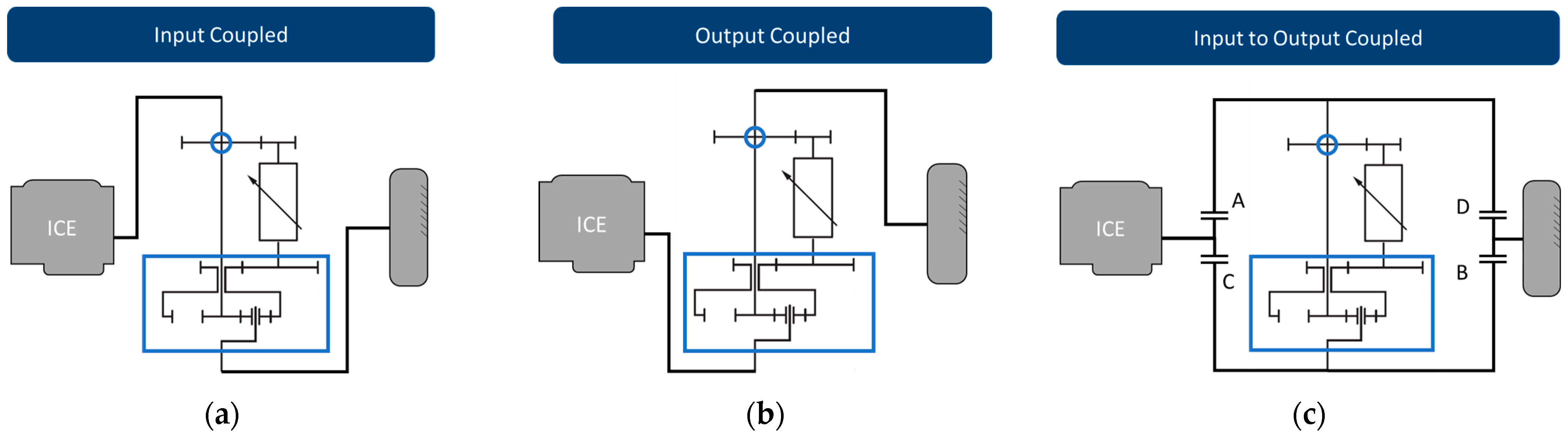
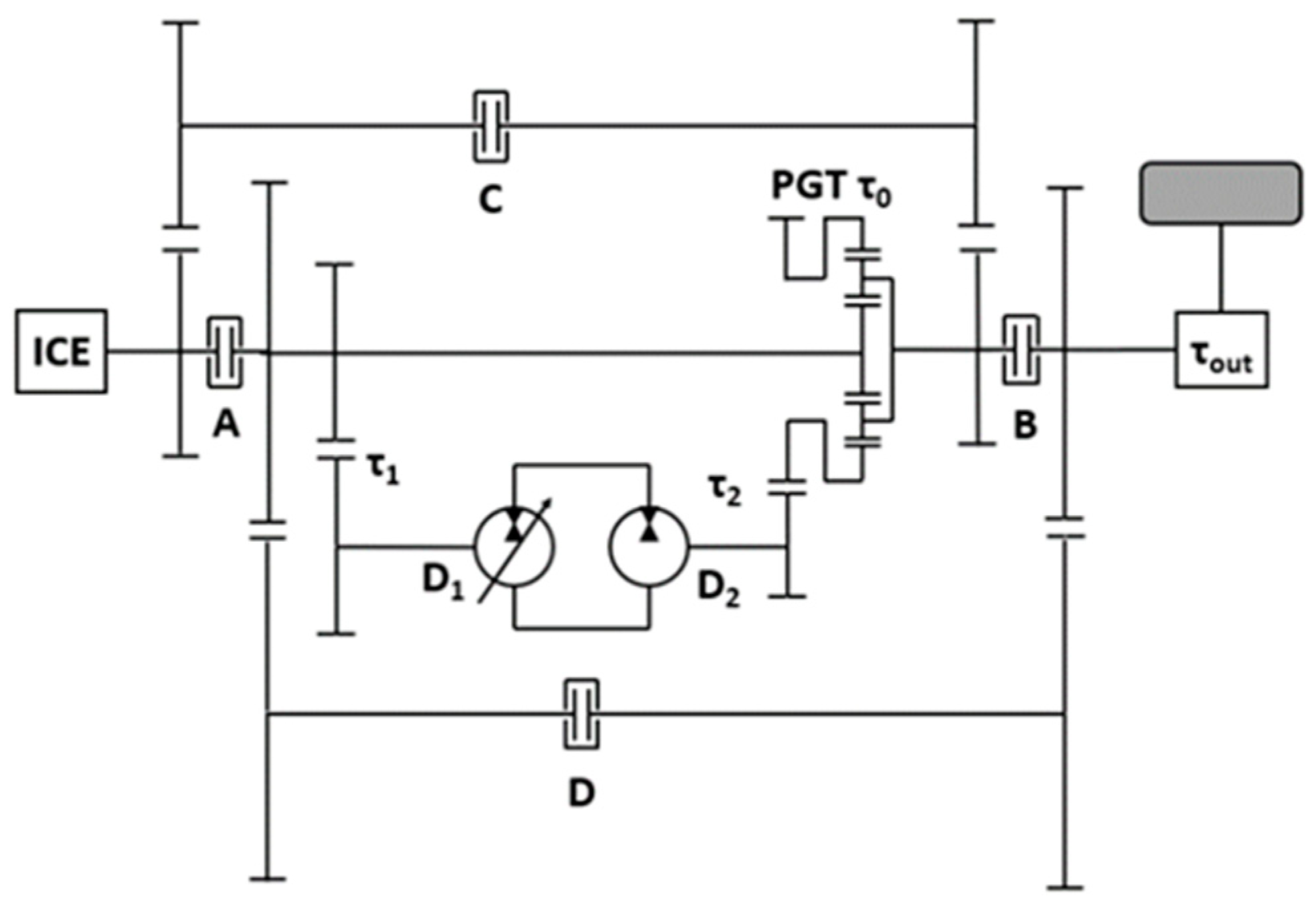
2.1. IC2OC Transmission

IC2OC transmission arises from the observation that the two simple layouts, IC and OC, differ only in the position of the epicyclic gear with respect to the engine and the hydrostatic unit (Figure 1a,b). Therefore, with a suitable series of connections, it is possible to pass from one layout to the other.
As shown in Figure 1c, by closing Clutches A and B and opening Clutches C and D, layout IC is formed; conversely, by opening the last two and closing the first two, layout OC is formed.
The IC2OC layout should have some advantages over the simple two. It is known that each of the two simple layouts has a functional condition in which the power is transmitted only through the mechanical way, called the full mechanical point, which is therefore characterized by the highest efficiency (Figure 2a,b). In the IC2OC layout, there are two FMPs, guaranteeing two high-performance zones (Figure 2c). A second advantage is the extension of vehicle speed without the need to adopt additional gears. Finally, observing the graphs in Figure 2, it can be deduced that switching from IC to OC, both FMP can be reached by regulating only one hydraulic machine, while the other has a fixed displacement. To avoid clutch slippage when switching from one scheme to another, the engine speed must be equal to the speed of the differential input shaft, as can be deduced from Figure 1 and from the following Figure 3.

2.2. Transmission Design
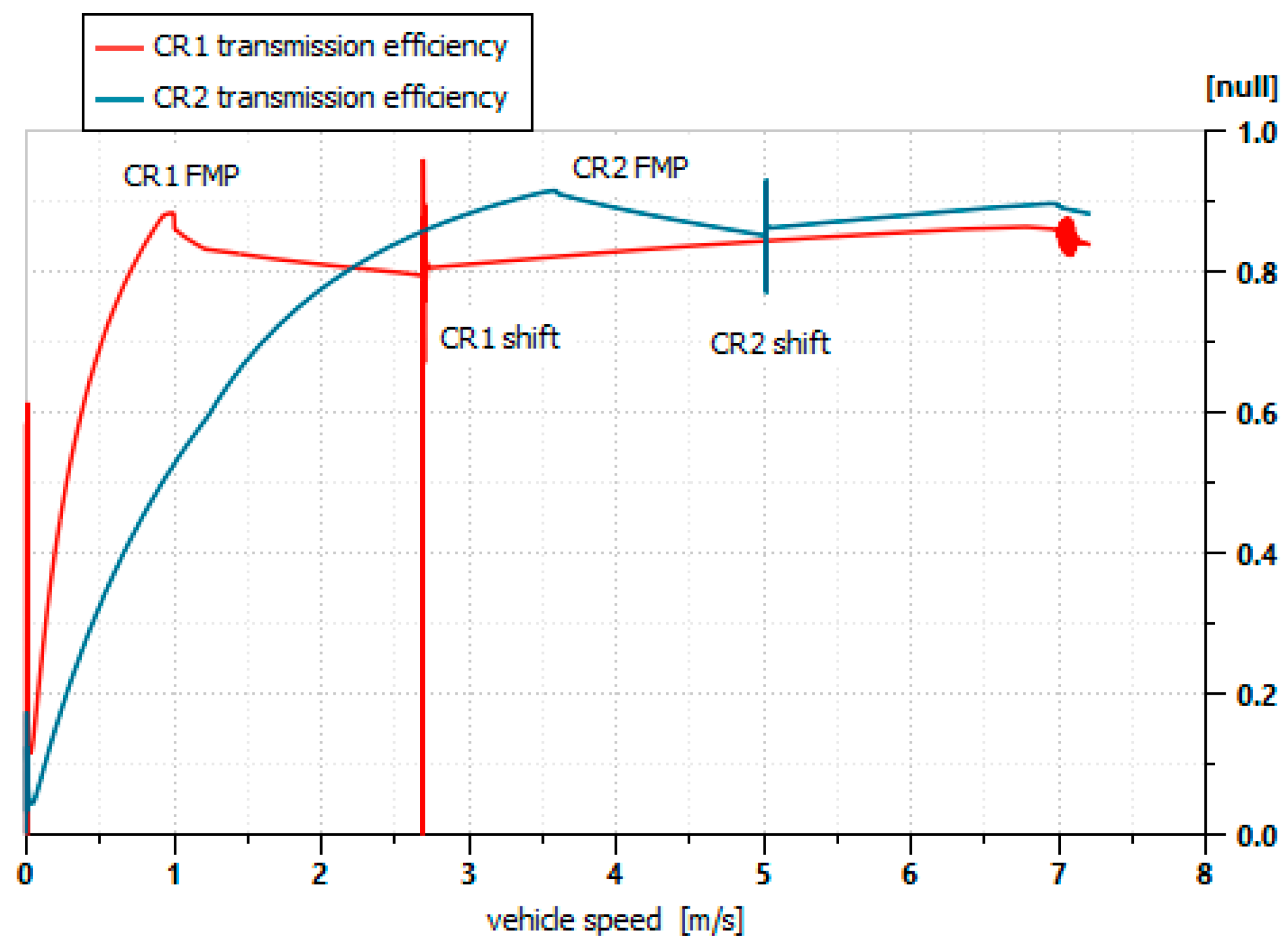
2.2.1. FMP Speeds

The scheme of IC2OC transmission is shown in Figure 3.
The transmission design requires the calculation of the standing gear ratio of the planetary τ 0 (see Figure 3), the transmission ratio of the ordinary gears τ 1 , τ 2 , the rear axle ratio τ o u t , the definition of the shifting speed V s h i f t , and the displacement of the two hydraulic machines D 1 , D 2 .
The design procedure develops as follows.
In the full mechanical point, the planetary ring is stationary and no power flows through it. So, the two FMP conditions for the transmission can be obtained via the Willis equation for the planetary gear (Equation (1)) by setting to zero the ring shaft speed.
τ 0 = ω r ω c ω s ω c
τ 0 ω s + 1 τ 0 ω c = 0
where ω is angular velocity, r, c, s stand for ring, carrier, and solar of the planetary, respectively.
In the IC mode, A and B clutches are closed:
ω s = ω i c e                     ω c = ω w τ o u t = V τ o u t R w ,
In the OC mode, C and D clutches are closed:
ω c = ω i c e                     ω s = ω w τ o u t = V τ o u t R w ,
where R w is the wheel radius and ice stands for internal combustion engine.
Combining Equation (3) with Equation (2), and Equation (4) with Equation (2), the expression of the FMP speed for both modes can be obtained.
V f m p I C = τ 0 τ 0 1 ω i c e τ o u t R w
V f m p O C = τ 0 1 τ 0 ω i c e τ o u t R w   .
Once the two FMPs speeds are chosen based on a suitable criterion, Equations (5) and (6) can be used to calculate τ 0 and τ o u t (Equations (7) and (8)).
τ 0 = k k 1   with     k = V f m p I C V f m p O C  
τ o u t = V f m p   I C · V f m p O C ω i c e R w   .
Since the FMPs are the functional conditions with the highest efficiency, their choice should be made carefully. In the following, two criteria for a non-arbitrary choice of these FMP speeds are presented and discussed.
  • First criterion
The first criterion (further referred to as CR1) refers to optimal FMP speeds obtained at maximum power conditions by the authors [15]. In summary, the optimal FMP speed of a simple IC layout is located at about 25–35% of the maximum vehicle speed. For the IC part of a IC2OC layout, the latter is equal to the shift speed. The FMP speed of a simple OC layout is located around the maximum speed to prevent the power recirculation mode, which is notoriously dissipative.
These suggestions applied to the IC2OC transmission lead to the following conditions:
V f m p I C = 0.25 ÷ 0.35 · V s h i f t = 0.25 ÷ 0.35 · V m a x · V f m p I C   V f m p I C = 0.06 ÷ 0.12 · V m a x
V f m p O C V m a x
  • Second criterion
The second criterion (further referred to as CR2) is based on this concept: since the FMP is the functional point with maximum efficiency, its speed should coincide with the most frequently used vehicle speed, or rather with the vehicle speed that processes the highest amount of energy. In this way, losses should be minimized. To achieve this, a characteristic duty cycle of the vehicle must be available, from which an energy-weighted frequency histogram can be extracted.
The synchronous shift between IC to OC modes requires the two speeds in Clutch B to be equal, i.e., ω c = ω i c e . So, the shift condition can be expressed by means of Equation (4):
V s h i f t = ω i c e τ o u t R w .
We observe that the shifting speed is equal to the geometric mean of IC and OC FMP speeds (Equations (5) and (6)).
The values of the remaining variables,   D 1 , D 2 , τ 1 , τ 2 can be calculated following a functional approach or an optimal approach.

2.2.2. Functional Approach

The functional approach is based on the functional equations of the transmission. The values of the transmission ratios τ 1 and τ 2 must not allow the two hydraulic units to exceed their maximum speed set by the manufacturer:
τ 1 = ω H y   M a x max ω I C E   ,       1 τ o u t   V m a x   R w ;   τ 2 = ω H y   M a x max ω r V = 0 V s h i f t V m a x   .
In the first equation, the denominator is the maximum speed the unit can assume, respectively, in the functional modes IC and OC. In the second equation, the denominator is the maximum ring speed under the starting, shifting and maximum speed conditions.
The hydraulic units have to be sized to maintain the hydraulic system pressure below the maximum design value and to provide a coherent flow rate between the two units:
D 1 = 2 π   T 1 Δ p m a x   ;     D 2 = 2 π   T 2 Δ p m a x .
α 1   ω 1 D 1 = ω 2 D 2 with α 1 < 1 .
The torques T 1 and T 2 must be calculated considering the following conditions:
  • Vehicle still, maximum pulling force, IC mode;
  • Shifting speed, maximum power, OC mode.

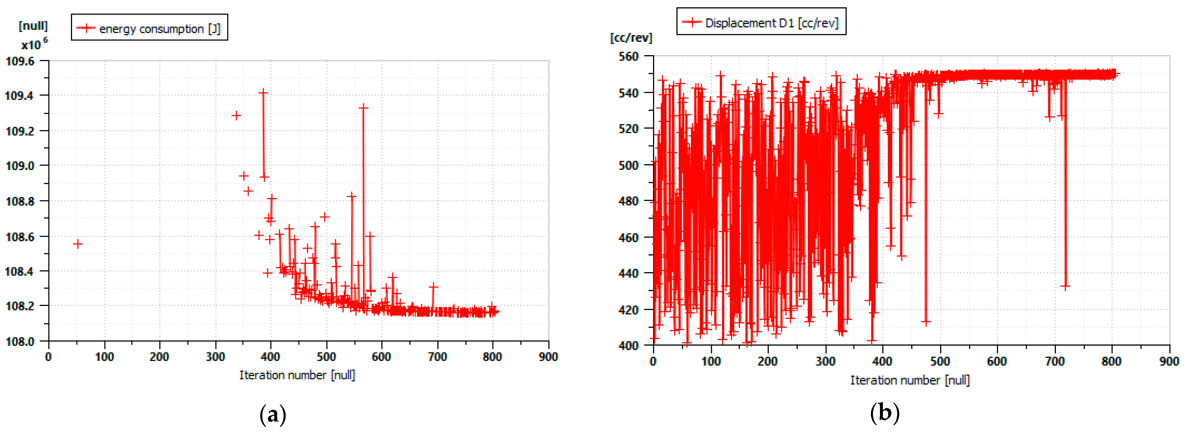
2.2.3. Optimal Approach

The four unknowns, D 1 , D 2 , τ 1 , τ 2 , can also be determined via an optimization problem: minimizing the energy required by the transmission to the engine, when the transmission is subject to design variables, design parameters and constraints, as well as to an appropriate load cycle.
For the present problem, the design variables are D 1 , D 2 , τ 1 , τ 2 .
The design parameters are:
  • engine maximum power and speed,
  • maximum vehicle speed,
  • maximum wheel pulling force,
  • wheel radius.
The design constraints are:
  • maximum pressure of hydraulic machines,
  • maximum speed of hydraulic machines as a function of displacement.
The load cycle must consider the entire vehicle speed range and the maximum level of the available power. Therefore, it can be made up of a speed profile linearly increasing from zero up to the maximum speed, with a constant power level equal to the maximum.

2.3. Case Study

In this part of the work, the CR1 and CR2 criteria are compared to determine the most effective for achieving high transmission efficiency; it is also verified how far the two previous criteria are from optimality. Therefore, for each of the two criteria, a functional sizing and an optimized sizing are carried out.
The study is conducted on an off-highway vehicle, the Kalmar Cargotec DRG Gloria 450 reach stacker [22], whose characteristic data are shown in Table 1.
The full mechanical point speeds for CR1 are assumed based on 3.3.1:
V f m p I C = 0.12 · V m a x = 3.2   k m / h
V f m p O C V m a x
The full mechanical point speeds for CR2 are taken from a study [25] performed on a cycle measured by Dana Rexroth [22] on the same vehicle under examination operating in the field. The energy-weighted frequency histogram, which is obtained from the statistical study, highlights a clear bimodal trend, with two speed peaks at which the two full mechanical points can be placed:
V f m p I C 0.5 · V m a x = 13   k m / h
V f m p O C V m a x

3. Results

The transmission model used in the subsequent simulations and optimization procedure has already been presented in [25].
The optimization-based transmission sizing was performed in the Amesim environment [26] using the genetic algorithm as a search method. The genetic algorithm processed an initial population of 20 individuals, with a reproduction rate of 80% and a mutation rate of 10%. The maximum number of generations was set at 50. The search ranges were limited to displacement values compatible with the catalog data of a well-known manufacturer. The progression of the genetic algorithm search is shown in Figure 4a for the objective function, and in Figure 4b for the displacement of pump D 1 . Analogous trends were observed for the other design variables. Figure 4a shows that the first 300 iterations find only one feasible solution. In fact, any values of the four design variables do not automatically generate a working solution. From a certain point onwards, the search is easier and quickly reaches the optimal values. The optimization process was started from different initial values of the design variables, arriving at the same results.
Both functional sizing results and the optimization results for the two criteria are shown in Table 2. They show that the search for minimum energy consumption pushes towards higher displacement values than those in functional sizing. This is justified by the lower relative weight that losses have at high displacements.
To comparatively evaluate the performance of the transmissions just sized, a series of simulations of the vehicle subjected to a typical work cycle was carried out. The cycle, shown in Figure 5, is made up of the speed profile of the reach stacker combined with the profile of the loads the vehicle must transport. The cycle was detected during an experimental campaign by DANA Rexroth [22].
The simulation results are summarized in Table 3.

4. Discussion

Table 3 shows the differences between the two speed selection criteria. In fact, reading the table horizontally, it is seen that CR2 criterion leads to a higher consumption than CR1, both in the functional configuration (+11.6%) and in the optimized one (+8.2%), contradicting the assumptions behind its definition. But on closer inspection, this result should come as no surprise, as the high FMP speed value of CR2 forces the transmission to work in recirculation for a wider range. Since the recirculation mode is less efficient than the additive mode, lower efficiencies should be expected. To confirm this, Figure 6 shows the efficiency trend for optimal geometries CR1 and CR2 at P = 220 kW and linearly increasing speed. It is observed that the peak efficiency of the CR2 layout is actually higher than the peak efficiency of CR1; however, the CR1 layout, thanks to its lower V F M P , has a much higher efficiency than the CR2 at low speeds, while at high and medium speeds its efficiency is only slightly lower.
To understand the difference between the two criteria, it is necessary to remember that the objective function used in [22] to obtain the CR1 speeds is the energy demand from the engine, i.e., an energy that comes from both load and transmission losses. In the second criterion, however, it is only the energy imposed by the load that is counted. Unless the criterion is integrated with an assumed transmission efficiency, this criterion cannot be considered reliable.
If Table 3 is read vertically, the weight of the optimization operation can be evaluated. When applied to the CR2 layout, it leads to a reduction in consumption of approximately 3% compared to the CR1 layout. However, it is observed that the latter does not derive any substantial benefit from the optimization: it shows the same consumption with very different displacements and ratios. From a numerical point of view, this means that the minimum area is very flat and wide variation in size leads to neglectable differences in efficiency. From a design point of view, therefore, the choice of smaller displacements does not lead to significant increases in consumption; on the contrary, smaller displacements imply smaller masses and, albeit slightly, lower consumption. Additionally, smaller machines cost less.
In summary, the CR1 criterion is able to lead to the optimized solution through a simple traditional calculation, without the need for a long and heavy optimization phase.
This result is justified by the common basis of the two methods: the load cycle with linearly increasing speed and maximum power. In fact, the optimal values of V f m p I C and V f m p O C are identified with this work cycle in [15], which is the same one used here in the optimization process, with the difference that in the first case the optimization is applied to two separate layouts, in the second to a single layout that unites them.
It is worth underlining that these results cannot be considered as general findings but can be considered valid only for the type of vehicle considered here.

5. Conclusions

A dual-type hydromechanical transmission is proposed whose configuration can be switched from the IC to the OC and vice versa with an appropriate clutch set. The transmission avoids the use of additional gears to achieve high vehicle speeds. Moreover, exploiting two full mechanical points, the transmission can have better performances than its two parent configurations.
The design process of this transmission requires knowledge of the full mechanical point speeds, which, by their nature, affect the overall performance of the transmission itself. Therefore, their choice must be made with caution. Two selection criteria are proposed.
In the first, the two speeds are the optimal ones for the two parent layouts; in the second, they are the most frequently used speeds in a standard work cycle.
The two criteria provide two quite different configurations.
The second type of design procedure involves mathematical programming as a sizing tool.
These two design techniques are compared for the transmission of a reach stacker.
It is observed that the first selection criterion is the most efficient and leads to a configuration that is far from the optimal one, but which has the same performance, both in functional and efficiency terms. This is a sign that the minimum consumption zone is quite large. Therefore, a choice of smaller machines leads to less expensive solutions with negligible loss of performance.

Author Contributions

Conceptualization, A.M, A.R. and N.A.; methodology, A.M, A.R. and N.A.; resources, N.A.; writing—review and editing, A.M., A.R. and N.A. All authors have read and agreed to the published version of the manuscript.

Funding

This research was funded by DOR 2022 of the University of Padua.

Conflicts of Interest

The authors declare no conflict of interest.

References

  1. Jarchow, F. Leistungsverzweigte Getriebe (Power Split Transmissions). VDI-Z 1964, 106, 196–205. [Google Scholar]
  2. Kress, J.H. Hydrostatic Power-Splitting Transmissions for Wheeled Vehicles. Classification and Theory of Operation; SAE Paper No. 680549; SAE International: Warrendale, PA, USA, 1968. [Google Scholar]
  3. Renius, K.T.; Resch, R. Continuously Variable Tractor Transmissions; ASAE Distinguished Lecture Series Tractor Design. 29; American Society of Agricultrual Engineers: St. Joseph, MI, USA, 2005. [Google Scholar]
  4. Blake, C.; Ivantysynova, M.; Williams, K. Comparison of operational characteristics in power split continuously variable transmissions. In Proceedings of the SAE 2006 Commercial Vehicle Engineering Congress & Exhibition, Rosemont/Chicago, IL, USA, 31 October–2 November 2006. [Google Scholar]
  5. Linares, P.; Mendez, V.; Catalan, H. Design parameters for continuously variable power-split transmissions using planetaries with 3 active shafts. J. Terramechanics 2010, 47, 323–335. [Google Scholar] [CrossRef]
  6. Casoli, P.; Vacca, A.; Berta, G.; Meleti, S.; Vescovini, M. A numerical model for the simulation of Diesel/CVT power split transmission. In Proceedings of the SAE-NA ICE2007, Napoli, Italy, 17–20 September 2007; SAE Paper n. 2007-24-137. SAE International: Warrendale, PA, USA, 2007. ISBN 978-88-900399-3-0. [Google Scholar] [CrossRef]
  7. Xiong, S.; Wilfong, G.; Lumkes, J., Jr. Components sizing, and performance analysis of hydro-mechanical power split transmission applied to a wheel loader. Energies 2019, 12, 1613. [Google Scholar] [CrossRef]
  8. Wan, L.; Dai, H.; Zeng, Q.; Sun, Z.; Tian, M. Characteristic Analysis and Co-Validation of Hydro-Mechanical Continuously Variable Transmission Based on the Wheel Loader. Appl. Sci. 2020, 10, 5900. [Google Scholar] [CrossRef]
  9. Wei, W.; Junlin, L.; Chunhui, W.; Hui, L.; Shihua, Y. Design and control of a hydro-mechanical transmission for all-terrain vehicle. Mech. Mach. Theory 2020, 154, 104052. [Google Scholar] [CrossRef]
  10. Pettersson, K.; Krus, K. Design Optimization of Complex Hydro-mechanical Transmissions. J. Mech. Des. 2013, 135, 091005. [Google Scholar] [CrossRef]
  11. Xia, X.; Sun, D. Characteristic analysis on a new hydro-mechanical continuously variable transmission system. Mech. Mach. Theory 2018, 126, 457–467. [Google Scholar] [CrossRef]
  12. Xia, Y.; Sun, D.; Qin, D.; Zhou, X. Optimisation of the power-cycle hydro-mechanical parameters in a continuously variable transmission designed for agricultural tractors. Biosyst. Eng. 2020, 193, 12–24. [Google Scholar] [CrossRef]
  13. Liu, F.X.; Wu, W.; Hu, J.B.; Yuan, S.H. Design of multi-range hydro-mechanical transmission using modular method. Mech. Syst. Signal. Proc. 2019, 126, 1–20. [Google Scholar] [CrossRef]
  14. Guo, Z.; Sun, D.; Xu, L.; Xu, R. Research on Continuous Power Shift Process of Hydro-Mechanical Continuously Variable Transmission. IOP Conf. Ser. Mater. Sci. Eng. 2020, 790, 012172. [Google Scholar] [CrossRef]
  15. Zhao, Y.; Chen, X.; Song, Y.; Wang, G.; Zhai, Z. Energy and Fuel Consumption of a New Concept of Hydro-Mechanical Tractor Transmission. Sustainability 2023, 15, 10809. [Google Scholar] [CrossRef]
  16. Rossetti, A.; Macor, A. Continuous formulation of the layout of a hydromechanical transmission. Mech. Mach. Theory 2019, 133, 545–558. [Google Scholar] [CrossRef]
  17. Ahn, S.; Choi, J.; Kim, S.; Lee, J.; Choi, C.; Kim, H. Development of an integrated engine-hydro-mechanical transmission control algorithm for a tractor. Adv. Mech. Eng. 2015, 7, 1687814015593870. [Google Scholar] [CrossRef]
  18. Rossetti, A.; Andretta, N.; Macor, A. On the use of the Disability-adjusted Life Year (DALY) estimator as a metric to optimally manage ICE emissions. Energies 2022, 15, 4386. [Google Scholar] [CrossRef]
  19. Zhu, Z.; Yang, Y.; Wang, D.; Cai, Y.; Lai, L. Energy Saving Performance of Agricultural Tractor Equipped with Mechanic-Electronic-Hydraulic Powertrain. Syst. Agric. 2022, 12, 436. [Google Scholar] [CrossRef]
  20. Ramdan, M.I.; Stelson, K.A. Optimal design of a power-split hybrid hydraulic bus. Proc. Inst. Mech. Eng. Part D J. Automob. Eng. 2016, 230, 1699–1718. [Google Scholar] [CrossRef]
  21. Andretta, N. Design Methods for Hybrid Hydro-Mechanical Transmissions of Heavy-Duty Vehicles. Ph.D. Thesis, Padua University, Padova, Italy, 2022. [Google Scholar]
  22. Mercati, S.; Panizzolo, F.; Profumo, G. Power split hydro-mechanical variable transmission (HVT) for off-highway application. In Proceedings of the 10th International Fluid Power Conference, Dresden, Germany, 8–10 March 2016. [Google Scholar]
  23. Legner, J.; Rebholz, W.; Morrison, R. ZF cPower—Hydrostatic-Mechanical Powersplit Transmission for Construction and Forest Machinery. In Proceedings of the 10th International Fluid Power Conference, Dresden, Germany, 8–10 March 2016. [Google Scholar]
  24. Rossetti, A.; Andretta, N.; Macor, A. Study of a dual layout Input-to-Output Coupled hydromechanical transmission. In Proceedings of the 2022 IEEE Global Fluid Power Society—PhD Symposium, Napoli, Italy, 12–14 October 2022. [Google Scholar]
  25. Rossetti, A.; Andretta, N.; Macor, A. Design considerations about the hydromechanical transmission IC2OC. J. Phys. Conf. Ser. 2023, 2648, 012054. [Google Scholar] [CrossRef]
  26. AMESim; Simcenter Amesim Version 2210; Siemens Industry Software NV: Plano, TX, USA, 2021.
Figure 1. Hydromechanical transmission layout: (a) IC transmission layout; (b) OC transmission layout; (c) IC2OC transmission layout.
Fluids 09 00073 g001
Figure 2. Characteristic curves: (a) Input coupled layout; (b) Output coupled layout; (c) IC2OC layout.
Fluids 09 00073 g002
Figure 3. Scheme of the IC2OC layout.
Fluids 09 00073 g003
Figure 4. Progression of the search during optimization for the objective function (a) and pump displacement (b).
Fluids 09 00073 g004
Figure 5. Working cycle of the reach stacker.
Fluids 09 00073 g005
Figure 6. Transmission efficiency for CR1 and CR2 layouts obtained though optimization (P = 220 kW, vehicle speed linearly increasing).
Fluids 09 00073 g006
Table 1. Main data of the test vehicle.
Engine DataUnit
Engine modelTAD-1150-VE-
Max power @ speed235 @ 1450–2000 kW@rpm
Max torque @ speed1581 @ 950–1450 Nm@rpm
Vehicle Data
Maximum Load112,400kg
Wheel radius0.825m
Maximum Torque at Wheel128,000Nm
Maximum Vehicle Speed26km/h
Gradeability at rated load17%
Table 2. Functional and optimal sizing results.
CR1CR2
nICE[rpm]20002000
nHymax1, nHymax2[rpm]2100/29002100/2900
Δpmax[bar]465465
Vmax[km/h]2626
VfmpIC[km/h]3.213
VfmpOC[km/h]2626
Vshift[km/h]918
τ0/−1/1.65−1/0.4
τout/6334
functionaloptimalfunctionaloptimal
D1[cm3]428550519550
D2[cm3]115296261471
τ1/0.450.380.730.63
τ2/1.510.630.5720.31
Table 3. Energy consumption (MJ) during the test cycle shown in Figure 5.
CR1CR2Δ CR2-CR1
Functional53.159.24+11.6%
Optimal53.0657.41+8.2%
Δ Optimal--Functional−0.1%−3.1%
Disclaimer/Publisher’s Note: The statements, opinions and data contained in all publications are solely those of the individual author(s) and contributor(s) and not of MDPI and/or the editor(s). MDPI and/or the editor(s) disclaim responsibility for any injury to people or property resulting from any ideas, methods, instructions or products referred to in the content.

