Abstract
The formation of flow-induced, oriented structures in two-phase systems, as in this study, is a phenomenon of considerable interest to the scientific and industrial sectors. The main difficulty in understanding the formation of bands of droplets is the simultaneous interplay of physicochemical, hydrodynamic, and mechanical effects. Additionally, banded structure materials frequently show multiple length scales covering several decades as a result of complex time-dependent stress fields. Here, to facilitate understanding a subset of these structures, we studied water in oil emulsions and focused on the effects of three variables specifically: the confinement factor, the viscosity ratio and the applied shear rate . The confinement is the ratio between the drop’s diameter () and the separation of (the gap between) the circular rotating disks () containing the emulsion. We carried out (a) observations of the induced structure under different simple shear rates, as well as (b) statistical and morphological analysis of these bands. At low shear rates, the system self-assembles into bands along the direction of the flow and stacked normal to the velocity gradient direction. At higher shear rates is possible to observe bands normal to the vorticity direction. Here, we show that a detailed analysis of the dynamics of the band structures is amenable, as well as measurements of flow field anomalies simultaneously observed. The local emulsion viscosity varies in time, increasing in regions of higher droplet concentration and subsequently inducing velocity components perpendicular to the main flow direction. Thus, the emulsion morphology evolves and changes macroscopically. A relatively plausible explanation is attributed to the competitive effects of coalescence and the rupture of drops, where values less than one predominate coalescence.
1. Introduction
The formation of oriented structures in two-phase systems, as in this study, and particularly the formation of bands of droplets, is a phenomenon that attracts considerable interest in the scientific and industrial fields. Its vast applications are directed to microfluidics, the food industry, and granular materials, among other possibilities. Some band formation studies have been reported in the literature for different types of samples, such as granular materials [1,2], stiff particle suspensions [3,4], liquid crystals [5], polymer solutions [6], in surfactant wormlike micelles [7,8], and attractive emulsions [9,10]. The arrangement of bands in emulsions is reported mainly for the concentric cylinder geometry [11], where band formation can occur in all three directions (the directions of the flow, the velocity gradient, or the direction of vorticity). These bands may depend on different variables of the flow or under specific and different conditions.
The essential difficulty of understanding band formation in biphasic systems is the simultaneous physicochemical, hydrodynamic, and mechanical effects. Additionally, it is quite common that banded structure materials show length scales covering several decades. For example, the characteristic length scales observed are as small as 0.3 while their macroscopic features extend over several millimeters [12]. In technologies of the order of micro and nano, where biphasic mixtures play an essential role, these physical processes are still poorly understood [13].
The trend of studies in this field recorded for a couple of decades suggests that band structures occur in complex fluids whose relaxation times are slow [14,15,16,17]. Some banded structures are observed after a long shearing flow—at a specific shear rate—and persist for a long time, while in other cases, bands are transitory since the isotropy of the emulsion is recovered after a short resting period a few times the duration of the applied shear flow [18].
However, recent reports show that the phenomenon can also be observed in relatively “simple” systems, such as two Newtonian liquids, immiscible and without surfactants [19]. Thus, the slow relaxation mechanisms can not be inferred from the dynamics of individual constituents. The slow mechanisms appear to depend on collective dynamics that are not easily determined or understood [20]. Next, we present a systematic study of the formation of bands in a water-in-oil emulsion with a 50/50 volume fraction and under a simple shearing flow. In particular, we address two aspects of the flow dynamics due to the combined effects of close boundaries and dissimilar viscosities of drops and suspending media, which simultaneously induce a 3D rearrangement of and migration of particles to deviations of the expected flow profiles.
Shear banding in the emulsion. Among the earliest reports of band formation by flows [17], the correlation with the shearing rate was emphasized, firstly in solid samples, then in mixtures of molten polymers, and finally in emulsions. However, in emulsions, the work of Caserta et al. [21] addresses the relationship between bandwidth and plate separation. Additionally, band formation is only observed in emulsions with a viscosity ratio of less than one. Consequently, inducing bands in emulsions is a relatively new and poorly studied phenomenon, even though it is highly relevant in the advanced manufacture of medical and optical devices, whose motivation lies in minimizing its components. Thus, the essential objective is to understand the relationship between large-scale physical phenomena and the microscale of its structure as well as, more importantly, the microscale at the macroscale [22].
When an emulsion is subjected to a simple flow, to improve the phenomenological understanding of the formation of banding structures, this work focuses on mainly three variables: the confinement effects (Co = 2R/H), the viscosity ratio, (), and the shear rate . The confinement (Co) is the ratio between the drop’s diameter (2R) and the separation between the circular disks (H). This dimensionless scale is frequently used when studying diluted systems, for example, an isolated drop. In the literature we find banded systems with p ~ 1 and values of confinement of 0.2 < Co < 0.56 [13], from which it is possible to create ad hoc scenarios for the formation of bands.
The scenarios of the morphological evolution induced by the flow are, initially, the alignment and elongation of drops (rotation and deformation); the second may be the coalescence of drops; and the third, when highly elongated, is their rupture into multiple smaller drops. These phenomena may happen simultaneously [23,24]. Moreover, after a long processing time, the evolution may show the fourth scenario: the formation of a banded structure.
The breakup of droplets under a shearing flow. Breakup usually happens whenever a higher than critical value of the shearing flow occurs, with this condition being defined by the critical capillary number, . That is, a breakup occurs when the drop’s surface stresses are overcome by the stresses of the flow. However, in the work of Grace [25] and that of De Bruijn [26], the rupture dynamics are shown to depend on and p. Furthermore, Bentley and Leal [27] report results for droplet deformation and rupture in a large class of two-dimensional linear flows, ranging from single-shear flow to pure elongational flow, where again, the critical capillary number and the viscosity ratio play a significant role. Furthermore, for emulsions subjected to simple shear flows, Jansen [28] has recently shown that the critical capillary number also decreases with increments of the fraction of the disperse phase; that is: .
The single droplet shapes and breaking up mechanisms of Newtonian liquids have been extensively studied [29]. If Ca << 1, the shape of the drop is slightly ellipsoidal, depending on the value of p, and remains aligned at an angle of 45° with respect to the flow direction. For higher (although small) values, the elongation of the drop increases in time until the steady state is reached. The drop simultaneously rotates and aligns closer to the flow direction.
Drop breakage is observed for values equal to and greater than the value of the critical capillary number. The different modes of rupture of a droplet depend on the viscosity ratio. For a viscosity ratio of less than one p < 1, the droplet acquires an elongated shape with a pointed end, as the tip streaming phenomenon occurs. For approximately equal to 1, the central portion of the droplet forms a neck (or necks) until followed by the breaking up into two daughter-droplets, with tiny satellite droplets between them. Additionally, , the droplets are deformed into long, thin fiber filaments that eventually break up through the capillary wave instability mechanism. These mechanisms become more complicated as the density of dispersed phase drops increases, and the length scales of a different object overlap considerably, including non-negligible effects due to the presence of the flow cell walls.
In this paper, experimental measurement of the banding in the direction perpendicular to the vorticity axis (parallel to the flow axis) of an emulsion in a parallel disk device is proposed. The band in the horizontal direction is quantitatively described with optical techniques and image analysis. Additionally, the band in the vertical direction (vorticity–gradient plane) is quantified assuming a linear profile, as shown in Figure 1 and droplet statistics analysis [30]. For each description, the basic equations and experimental results are stated. They are further discussed in terms of the results reported in the literature. The contribution in the description of the physical phenomenon of band formation is simple and aims to highlight the non-triviality of band formation.

Figure 1.
Schematic representation of the shearing device: parallel-disk geometry with a diameter of 36 mm and a gap of 0.1 mm. The emulsion (green color), is sandwiched by two quartz discs (cyan color) and two silver plates (gray) for efficient temperature control. The movement of the lower disk imposes a simple shear field on the emulsion, generating a velocity profile (red arrows between the plates), the initial hypothesis is of a linear and unidirectional velocity profile. The coordinates are designated as the flow axis in the direction of flow, the gradient axis in the direction of the velocity gradient, and the vorticity axis in the direction perpendicular to the flow-gradient plane.
2. Materials and Methods
MATERIALS: We have studied emulsions W/O—a mixture of alkanes for the continuous phase and an aqueous solution as the dispersed phase—, with very similar densities; . The aqueous solution is (w/W) 10 µM polyethylene oxide, CAS#372781, Sigma-Aldrich, St. Louis, MI, USA) and 3% 2-propanol (CAS#190764, Sigma-Aldrich) in 97% ultra-pure water (resistivity ≥ 18.2 MΩ∙cm; ρ = 0.997 g/mL). The continuum phase is a mixture of polybutadiene (CAS#181382, Sigma-Aldrich), heptadecane (CAS#128503, Sigma-Aldrich), 1,2,4-trichlorobenzene (Sigma-Aldrich CAS#132047), and eicosane (CAS#219274, Sigma-Aldrich). It was prepared in a glass bottle by first mixing 39.69% heptadecane with 7.56% eicosane, while maintaining it at 30 °C, and then adding a mixture of 6.25% polybutadiene and 46.5% 1,2,4-trichlorobenzene. The use of these materials was for three purposes; the first to mimic the rheological behavior of a mixture characteristic of the Mexican oil industry, the second to achieve an optically observable mixture under the selected study conditions, and the third to modulate the densities of the two emulsion phases and minimize the effects of phase separation by gravitational forces.
METHODS: The dispersed phase has a dynamic viscosity of 0.57 Pa·s, and the continuous phase a dynamic viscosity of 2.08 Pa·s, at 30 °C, respectively, within a shear rate range of 0.01 to 10 (s−1). The viscosities of the fluids were measured with an ARES G2 Rheometer (TA Instruments, New Castle, DE, USA). The viscosity ratio was p = 0.27.
The density of the two fluids was adjusted to minimize sedimentation in the emulsion with 2-propanol (aqueous solution) and trichlorobenzene (alkane mixture). The interfacial tension was determined by the deformed drop retraction (DDR) method proposed by Luciani et al. [31]. A set of eleven drops of 40% dispersed aqueous phase in the oil phase were evaluated to determine the average surface tension of 0.11 mN/m.
For the elaboration of the 50/50 emulsion (calculated as weight by weight), a homogenizer (Omni Inc., NW Kennesaw, GA, USA) with a fine sawtooth generator probe of 10 mm × 95 mm (SKU#15051) was used, rotating at 3000 rpm for 300 s, and at a constant temperature of 30 °C. It was stored at 30 °C for 48 h to verify its stability and ensure that any possible air bubbles had been eliminated. Subsequently, the emulsion sample was placed on the bottom disk of the shear flow cell, and the top disk was carefully placed on top without touching the sample, and then the disks were slowly compressed (squeezed) to a gap of 100 μm. It was kept like this for ten minutes to reach a temperature of 30 °C and erase any possible residual stresses and thermal histories. Additionally, a prior shear flow of 0.075 s−1 was applied for eight minutes in all measurements. Subsequently, a ramp sequence of constant shear rate, , was applied, from 0.75 s−1 to 4.5 s−1, with increments of 0.75 s−1. Each ramp step was ~400 s, followed by an ~18 s no-flow rest time, long enough for the droplets to reach a spherical shape.
All experiments were carried out using the parallel disk geometry (Linkam CSS450, Linkam Scientific Instruments, Honeycrock Lane, Salfords, UK)), schematically shown in Figure 1. The upper disk remains motionless; meanwhile, the lower disk rotates to impose a shearing stress on the emulsion. The observation window ( mm), located 7.5 mm from the center of rotation of the lower disc, allowed us to take images of the flow structure on the vorticity–velocity observation plane. All images of the emulsion’s banded structures correspond to an observed area of 1000 × 1340 µm2; that is, only 22% of the open field of view, and less than 0.6% of the total volume of the sample. Thus, on the observation plane of the flow, the real extension of these bands cannot be fully asserted, precluding a better understanding of the role that broad time and length scales may play in this phenomenon. All measurements reported in this paper were made with a 0.1 mm gap between the discs and a temperature of 30 °C. For this geometry, the shear rate is defined as , where the angular velocity ω is in rad/s, and the radius of observation and the separation between the plates are in mm.
The Visualization of microstructure evolution was carried out with a Nikon SMZ-U (Nikon Corp., Tokyo, Japan) light microscope. A Nikon Digital Sight DS-2mV camera was arranged in a bright field lighting arrangement for image capture. Images were processed with ImageJ® (version 1.53f51)software (National Institutes of Health, Bethesda, MD, USA), automatically and manually. The high turbidity disappeared as the shear rate increased and was adjusted with proper light exposure.
3. Results
3.1. The Horizontal Distribution of Drops (Vorticity–Flow Plane)
In this paper, bands appear from an initial, spatially homogeneous emulsion. However, prior to the observation of bands, other measurable phenomena that dominate the structural evolution of the emulsion may appear after the application of a constant shear rate. Among them are the increase in the average size of the dispersed phase, the evolution from a monomodal to a bimodal distribution, the eventual coalescence, the self-organization in necklaces, like a string of pearls, once again the eventual coalescence, the formation of strings, and their breakup [30], among other possible phenomena.
The observed accumulation of drops into a banded structure seems to imply that there is an underlying flow with a complex velocity field, not like simple shear flow and most likely a fully three-dimensional flow field, even when the shear rate’s effects on the drops’ deformation are weak. That is, on the one hand, and assuming mostly quasi-spherical drops, the simplest structural model (for emulsion with a viscosity of the mixture, ) implies a lower viscosity for regions of a low fraction of the aqueous phase. Thus, regions of high droplet counts will indicate a relatively higher viscosity with respect to neighboring regions of low drops’ concentration. On the other hand, if drop interactions are significant due to closeness among themselves, an extra stress field may be present, and a higher viscosity could be associated with a higher concentration of drops [32]. In both cases, the gradient in the viscosity within different regions may exist. For any homogeneous stress field within the flow—as is the case of steady simple shear flow devices—it is implied that lower viscosities (lower drop densities) move faster than higher concentration domains.
Thus, whenever horizontal bands are observed, the relative viscosity along the vorticity axis should be an oscillating function of position with a steady whole viscosity value that is made up of alternating regions of low and high viscosities. Hence, the horizontal profile of the velocity field along the flow direction may also show a sinusoidal variation along the z-axis and the vorticity axis, with a periodicity similar to that shown in the supplementary section, in particular Figure S7e.
Consequently, to visualize this phenomenon during the constant flow regime (towards the end of the transient state and for each shear rate), the velocity of individual drops along the flow direction, but with different radial positions, were measured and mean values were calculated . The radial variability of the mean velocity, , across valleys or peaks was evaluated. The droplet velocity was assumed to be constant for the steady-state flow for each shear rate applied to the sample. For each frame, the open-shutter time is one second; therefore, the displaced distance, , of each droplet was measured in ImageJ® software, and the drop velocity, , was calculated.
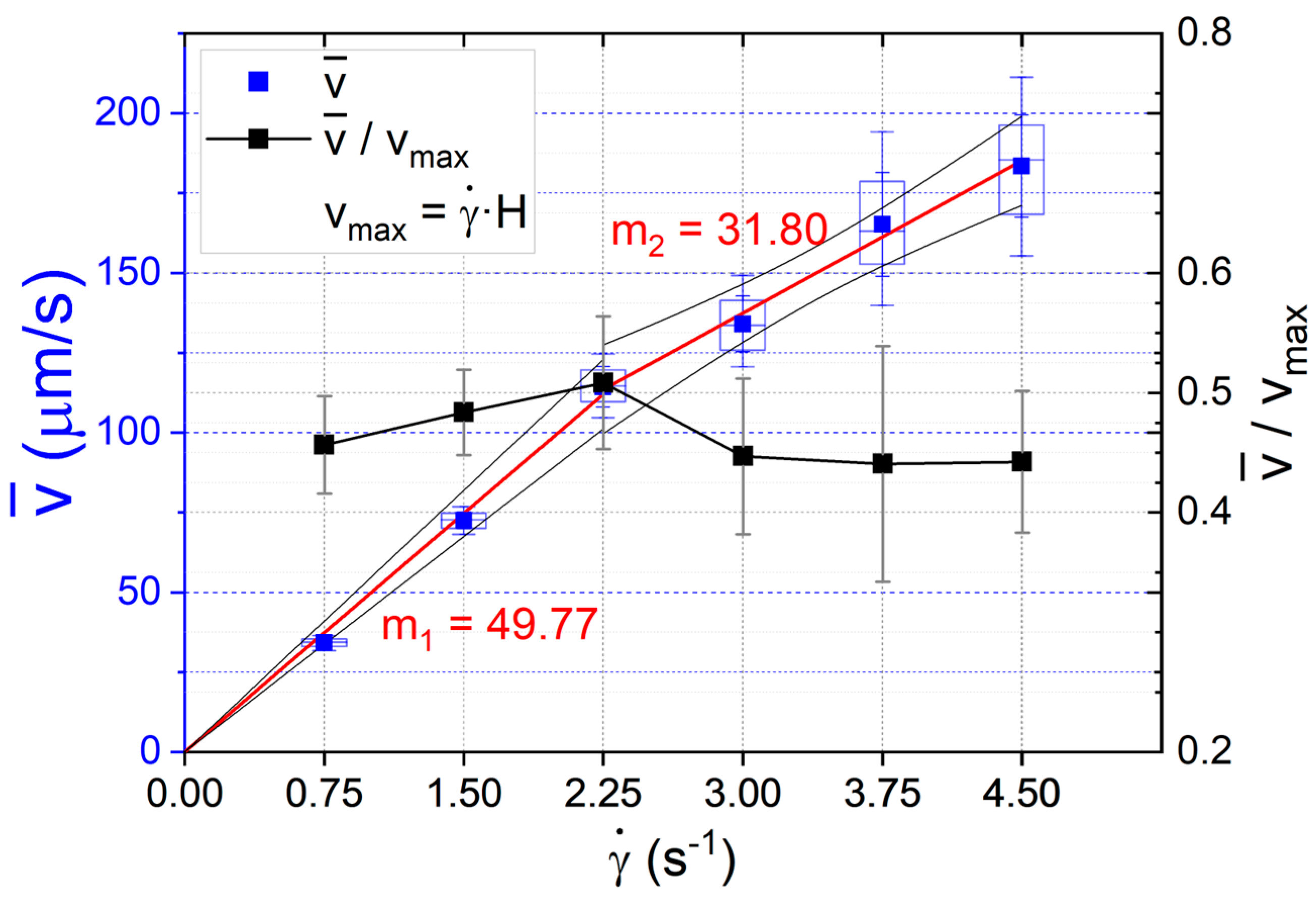
Table 1 summarizes the observed velocities for a selection of drops for which the tracks are unambiguous. Figure 2 shows the mean velocity obtained for all shear rates, indicating a linear behavior of the velocity with respect to for the weakest flows: The rate of increase slows down once the banded structure appears: , and has twice the uncertainty of the evaluated speeds (see Table 1; rightmost column). Additionally, the middle quartiles and the error bars are shown. The normalized dimensionless mean velocity, with respect to the velocity of the shearing disk (), corresponds to the right ordinate. Slopes , and show a notable slow down of the flow once the banded structure of the emulsion occurs. Accordingly, the slow down of the normalized velocities is homogeneous and is about for the three highest shear rates (3.0, 3.75, and 4.5 s−1).

Table 1.
The velocity of drops (randomly selected) was observed for different shear rates.
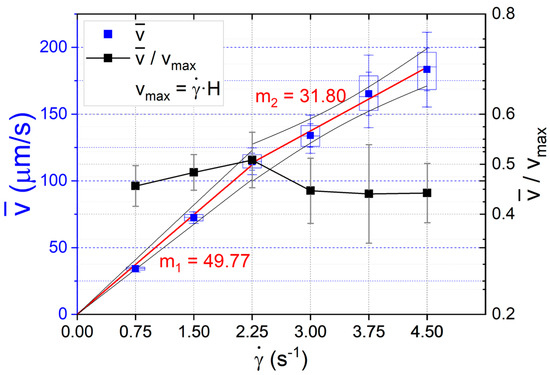
Figure 2.
The average speed of droplets over the complete flow domain (= 0.75, 1.50, 2.25, 3.00, 3.75, and 4.50 s−1), chosen for each shear rate; left ordinate. Additionally, the middle quartiles and the standard deviation bars are shown (blue). The slopes are (linear fit, R2 = 0.99) and (linear fit, R2 = 0.99) for the average droplet velocity values before () and after () which show a slowing with the formation of a band structure. The normalized dimensionless mean velocity with regard to the velocity of the shearing disk () and standard deviation bars; right ordinate. A significant decrease is observed for values of = 3.0, 3.75, and 4.5 s−1. The values of the comparative t-test with are 8.44, 6.84, and 10.36, respectively, with p-value less than 0.0001 in all cases.
As the shear rate increases, the observed increase in the standard deviation values is due to intrinsic difficulties in evaluating the average speed of drops in a flow that may no longer be laminar, as indicated in Table 1 and shown in Figure S8. The uncertainties for measured velocities increase, especially for those flow structures with a banded distribution of drops. This may imply that two phenomena are at play. The first one is simply an increase in collision rate between drops—particularly in the high concentration regime regions, inducing a slowdown of the measured velocity of individual drops. Moreover, the second may be due to a concentration-of-drops-dependent viscosity, with low drop concentration regions associated with lower viscosity, and thus, a higher velocity for a drop.
This scenario implies that the velocity profile for a lamella on the flow–vorticity plane shall also show an oscillatory pattern. This pattern should be similar to the concentration of drops profile, normal to the vorticity axis. The velocity profile shall match the spacing of bands and have higher velocities in regions of lower drop volumetric concentration.
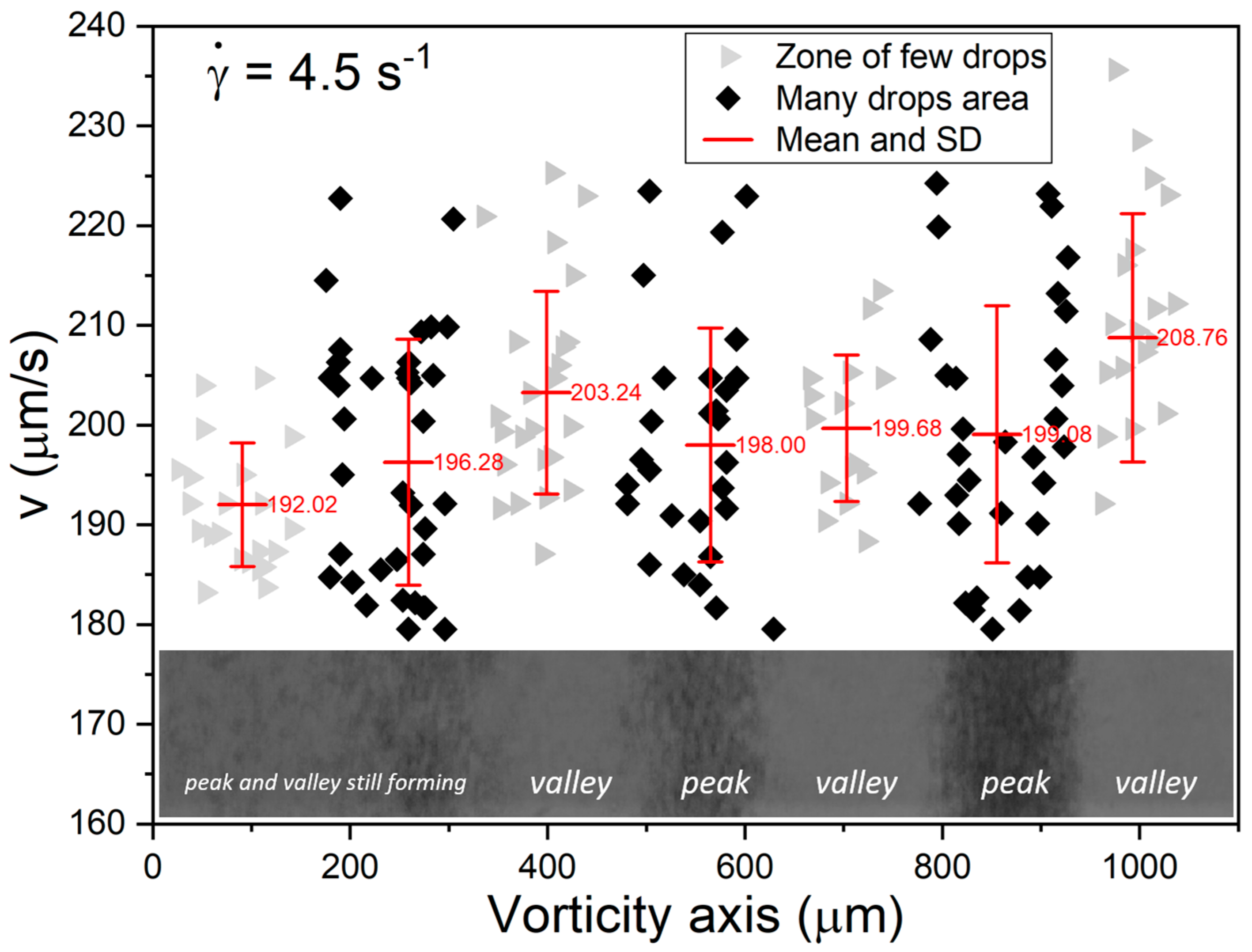
Figure 3 shows that low concentration regions do not have many available drops; thus, the number of data points is low. In contrast, regions with a high concentration of droplets may present many possible candidates for their velocity calculation, but frequent interaction with many neighbors limits the number of useful candidates (see Table S1).
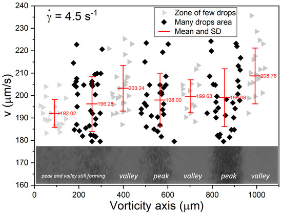
Figure 3.
For the shear rate of 4.5 s−1, the highest average velocities correspond to a low concentration of droplets, except where the boundaries of a band are not yet defined, e.g., average velocity 192.02 um/s. The bands develop and define their boundaries in the centripetal direction. The valleys correspond to a low population of drops and peaks to a high population of drops (see Figures S4 and S5). Velocities of some droplets along the flow direction vs. their position across the vorticity axis (measured from the lower-left corner of the captured frame). Plots of the measured velocity for individual drops for each marker with the average velocity over the valley or peak of the drop distribution profile and the bar is the standard deviation.
In addition, Figure 3 shows the oscillatory character of the mean velocity of drops within a given region across the vorticity axis (shown by a red trace). In particular, the mean velocity profile shall match the spacing of bands and have higher velocities in areas of lower droplet volumetric concentration, which can be inferred from the image of the banded structure of the emulsion at the bottom of the graph.
Thus, the information from Figure 2, Figure 3 and Figure S7 allow us to propose that the profile of velocities along the flow direction, spanning the full vorticity direction (that is, vorticity–flow plane), is non-homogenous, with a speed oscillation characterized by the same spatial frequency as the concentration of drops of the banded structure.
3.2. The Vertical Distribution of Drops (Vorticity–Gradient Plane)
Suppose the horizontal distribution of drops observed in Figure S7 induces a velocity distribution (an oscillatory velocity profile, as shown in Figure 3) along the flow direction for all drops. In that case, the character of the flow field may be fully three-dimensional, even when it is generated by a flow cell with perfectly flat parallel surfaces. This assumption can be plausible due to several effects, which may occur simultaneously. Consequently, these phenomena may also indicate that the vertical velocity profile is no longer linear, mainly due to a slowdown in the central lamella of the flow, as shown in Figure 2 for shear rates .
In particular, the slowdown of the mean flow is clearly non-homogeneous across the lamella, as seen in Figure 3. Both pieces of information are especially important and suggest that the velocity along the vorticity axis is no longer zero or homogeneous. In fact, this assumption could be plausible and may be explained by the oscillatory character of the flow field that induces a lateral component of the velocity along the vorticity direction (inducing gradients of the concentration of droplets observed in the banded structure).
There must be a component of the velocity field along the vorticity direction which is weak but characterized by an oscillatory manner. This normal component of the velocity field assures the development of a banded structure. The deceleration along the flow direction, as well as the appearance of a lateral (vorticity) component, may also indicate that the vertical velocity profile will be three-dimensional.
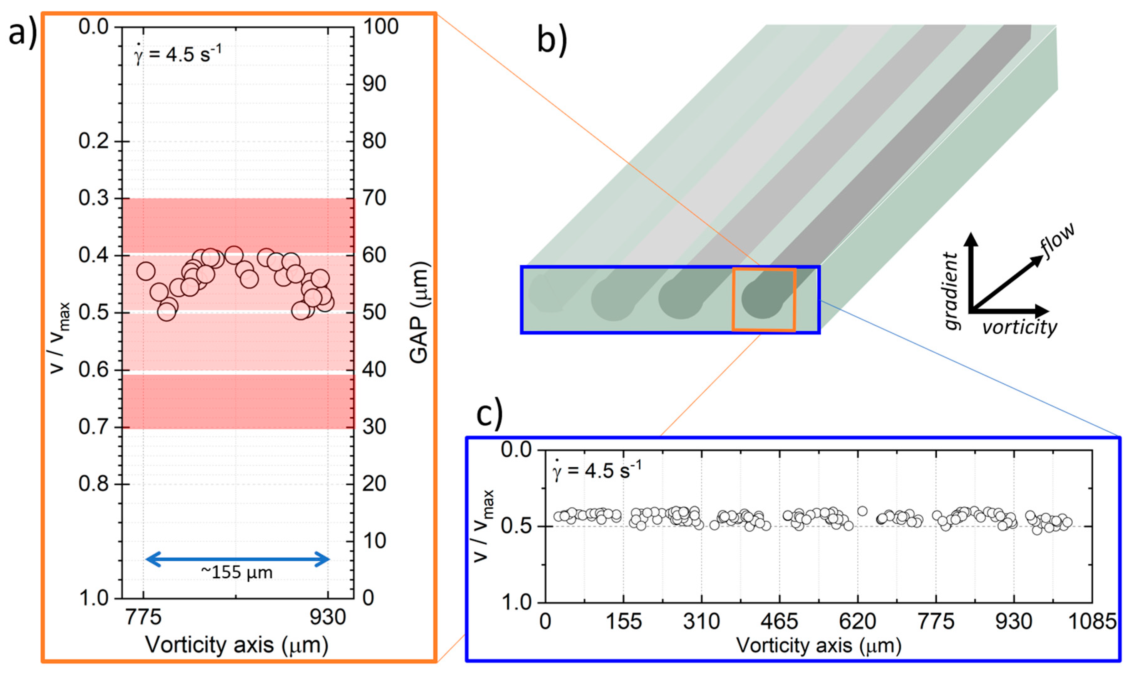
In order to study the profile of the concentration of droplets and the vertical velocity profile of the bands, Figure 4b shows an illustration of the captured image view in three dimensions and the initial assumption of a linear, unidirectional velocity profile. Furthermore, the figure hypothesizes from the dimensionless droplet velocity results that the vertical distribution of the band is not homogeneous; however, this suggests that it is centered between the plates and circular symmetry. In the lower part of the profile is the maximum velocity, , and in the upper part, the zero velocity (static top disk). Figure 4a,b shows dimensionless velocity measurements across the vorticity–gradient plane (with the value of zero in the lower left corner of each captured image), for s−1. It is possible to identify different bands separated by an approximate width of , and this value is validated with the distance between the peaks in Figure S7.
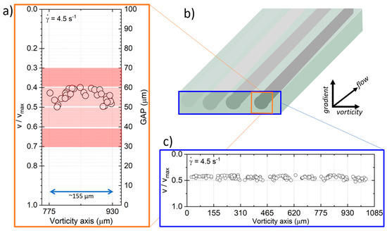
Figure 4.
An illustration captured image view in three dimensions and the initial assumption of a linear, unidirectional velocity profile. Furthermore, hypothesizing from the dimensionless droplet velocity results that (a) the vertical distribution of the band is not homogeneous, but suggests that it is centered between the plates and circular symmetrical. (b) Illustrates three gray bands, the band with well-defined boundaries is dark gray and the band in the process of formation is light gray. In (a,c) the dimensionless velocity across the vorticity direction is hsown. Each circle represents the position of a droplet, measuring its speed, , with the displacement measured by each frame and being the elapsed time. (a) Comparison of (right axis) and the separation between the disks (left axis) of the observed drops. (c) Complete profile constructed with the measured velocities of the observed droplets. The reconstruction and quantification of the thickness of the band in the vorticity gradient plane for a shear rate of 4.5 s−1.
Carrying out a characterization of the vertical velocity of droplets profile, as shown in Figure 4c, it is now possible to determine the profile of the concentration of droplets in a band now in the gradient-vorticity plane, at least for the better-defined bands. This analysis attempts to elucidate whether the band structure occurs from disk to disk of the shearing cell. However, given that the concentration of droplets is quite large and, in fact, sufficiently high to preclude observation of the velocity of droplets near the bottom of the flow cell, the measurement of velocities of droplets corresponds to those in the upper half of the flow field, only.
Thus, based on the velocity of individual droplets and using their normalized velocity to infer their vertical position on the band, it is possible to propose a vertical profile for the concentration of droplets within a high concentration band. Figure 4a. shows the possible position of droplets and the corresponding upper layer where droplets are located.
The droplet concentration within the red region, shown in Figure 4a, is postulated by symmetry considerations that can only be determined by measuring the droplet velocity. The dark red layer is the approximate thickness of the band without considering droplet diameters. At the same time, the green inset corresponds to the thickness of 100 µm. Thus, the area with a high concentration of droplets (the thickness of the band), when taking into account the diameter of the droplets, can be at a value of ~40 µm. The observed diameter of the droplets within this band zone is of the order of 15 to 30 μm and is also taken into account to delimit the thickness of the light red layer. In this way, a possible (actually, the minimum) complete profile is predicted, which is only a fraction of the wall separation, thereby indicating quite thick regions above and below with only a few drops (while the lamella maintains a high concentration of droplets). The confinement parameter of the band as a whole is , which is considered as moderate confinement in the literature [33].
4. Discussion of Results
Critical Capillary in Banding
For a single drop embedded in a continuum, with a viscosity ratio of and drop size of , the literature estimates that reasonable values of the critical capillary number in simple shear flow are about [29]. In the present paper, the critical capillary is , which may imply that other perturbations from nearby drops can induce the rupture of drops at a lower . These observations suggest that the perturbations are caused by the confinement of the dispersed phase in the emulsion.
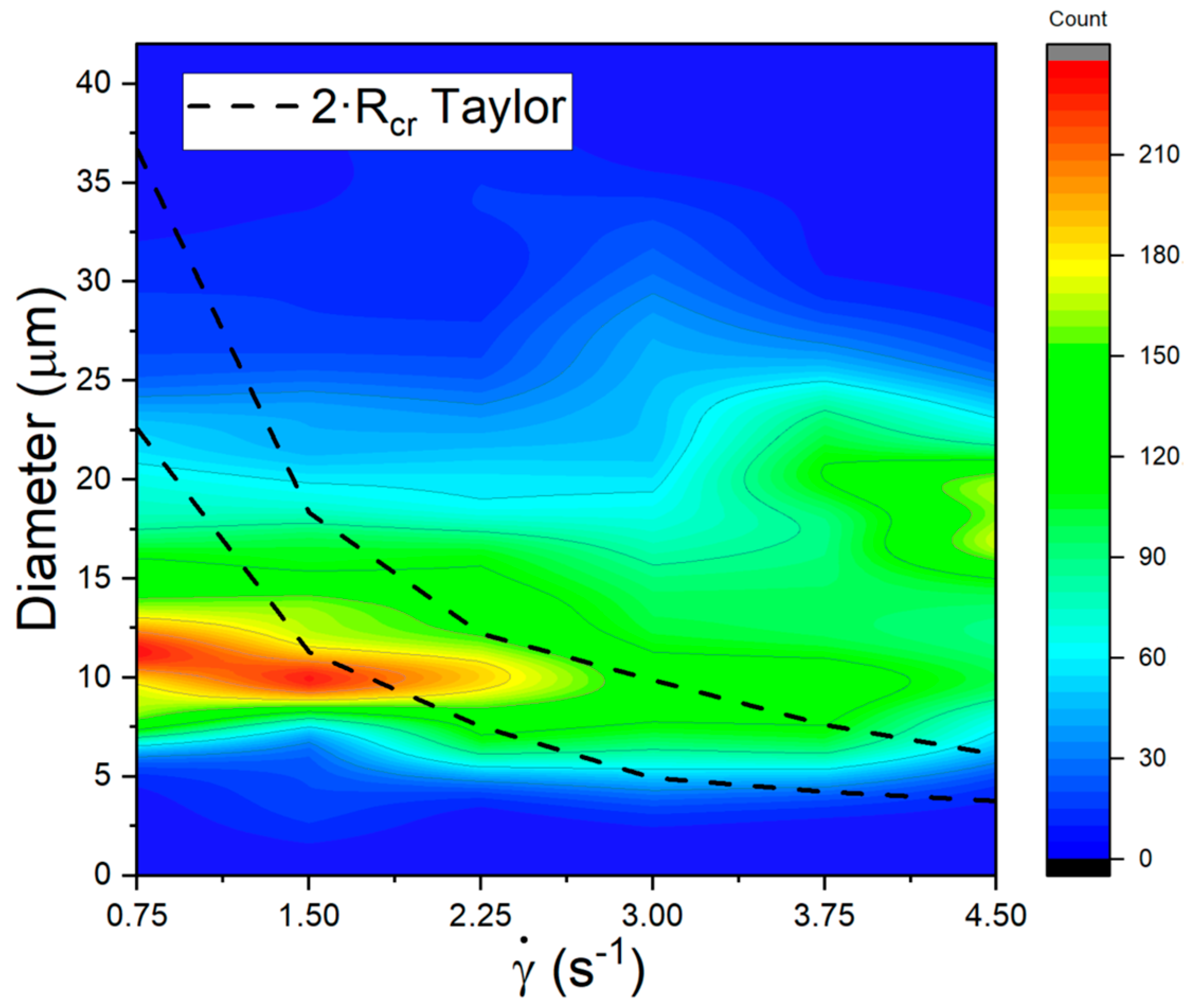
Recalling Taylor’s model prediction for the critical capillary, for a system with a constant value of, the value of implies that the critical radius, , the largest radius value up to drops of stable shape and the shear rate are inversely proportional, . The observed discrepancy of these two values can now be used to understand a portion of the dynamics observed in relation to the band’s structure. In other words, the critical radius of a drop decreases as the shear rate increases, as shown in Figure 5 (the region delimited between the black dashed lines). According to Taylor’s predictions, these upper and lower limits of the critical diameter values are analytical results valid for slow flows. This figure also shows the complete evolution of the histograms of the drop size distribution for the complete set of shear rates studied; the colored information portrays the histograms reported in [30].
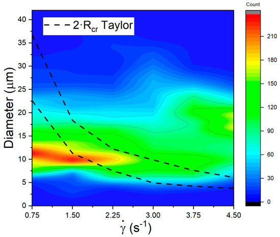
Figure 5.
Distribution of size of drops in the emulsion vs. the complete range of shear rates used in the experiments; frequency of drops are color-coded. Comparison of diameter , obtained with the critical capillary () for Taylor’s model. Black dashed region; the delimited area represents the range of stability for a single drop.
Please note that no drops smaller than appear, as well as no drops larger than 3 The highest frequency occurs at low shear rates and for diameters of about 12 . Drop elongation and rupture of these drops do not occur until when . Higher shear rates preclude the observation of drops with a diameter of approx. 12, hence a coalescence mechanism for the growth of drops must be balanced by another elongation and rupture of drops.
For shear rates no drop shall be stable for diameters larger than 12 , implying that the observed stability of larger drops (i.e., about 16–20 ) should be due to other stabilizing phenomena, mainly from nearby drops and a more complex flow regime. Additionally, for , drops larger than 8 only exist when strong interaction with other drops occurs, and the flow regime is more complex than simple shear flow. In particular, these mechanisms appear to inhibit the existence of a drop larger than .
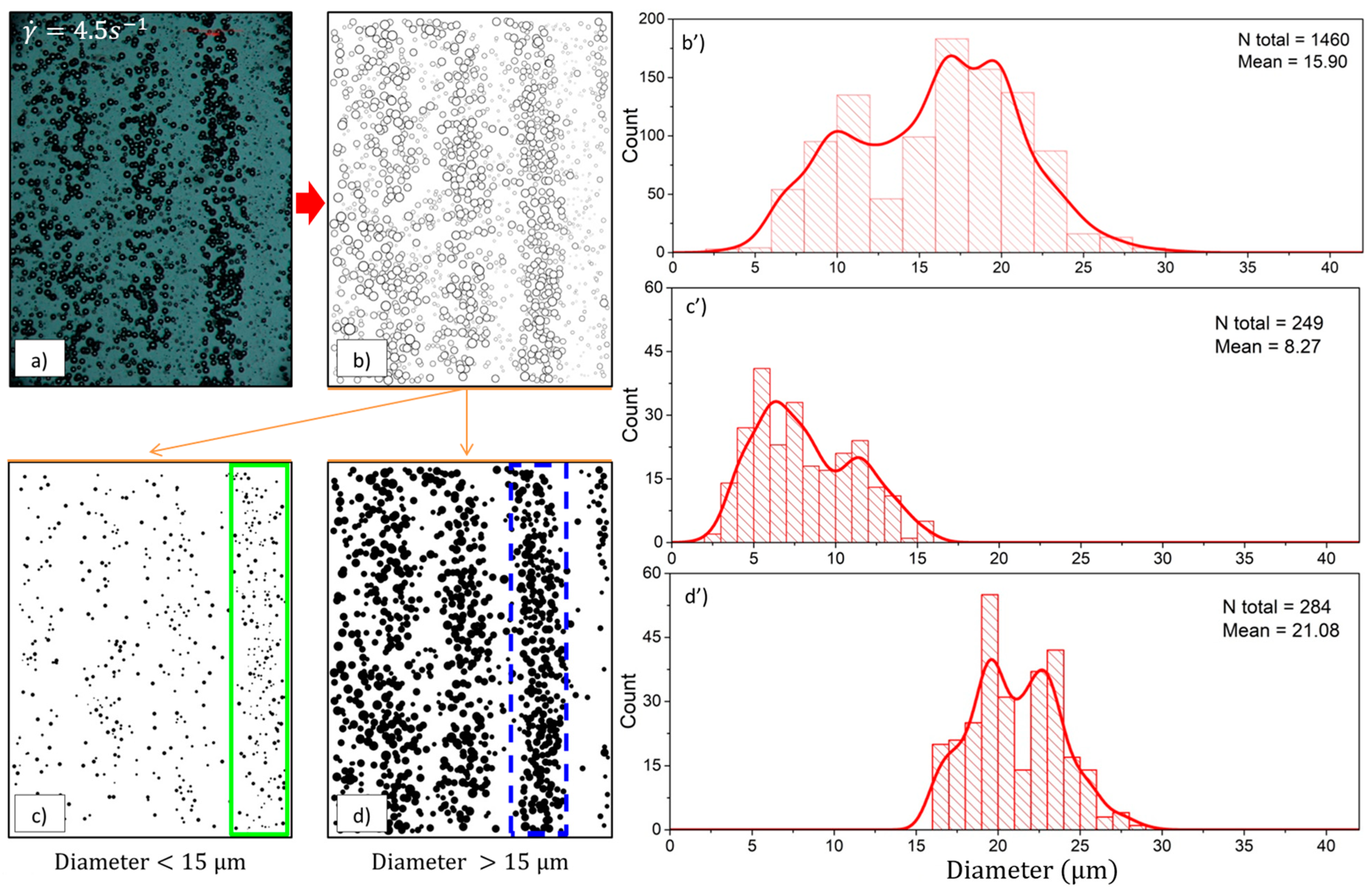
Figure 6 shows the location of the more massive drops inside the image, which are mostly contained within the high concentration band, while smaller ones appear mainly inside the valleys between bands. The average diameter of the drops inside the bands is above the critical diameter of the single drop Taylor model (see Figure 5). In this way, even in this dilute regime, and for drops confined in concentrated regions.
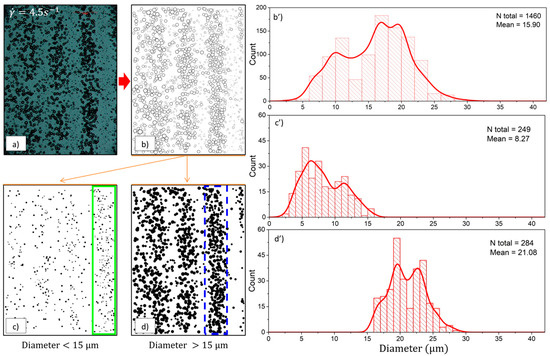
Figure 6.
Correlation of position of a drop inside a slice of the flow–vorticity plane and the expected diameter of the drop. (a) Image taken after a constant and just after the flow disappeared; (b) processed image selecting spherical drops only, total number of drops counted ; (c) selection of drops with diameters < contained in the green area; (d) selection of drops of diameters > contained in the blue area; and (b’) histogram for drops after 2410 s, at (corresponds to image (b)), (c’) histogram of droplets contained in a valley (green region in (c)) and (d’) histogram for flow region of high concentration droplets (blue region in (d)).
Therefore, this paper presents another possible explanation for the observed behavior in concentrated emulsions with bands present. This explanation is based more on the fact that the observed concentration gradients are concomitant with correlated gradients of the velocity field along the direction of the flow and the appearance of a non-zero component of the velocity field in the direction of the vorticity.
Previous attempts to explain the observed drops distributions were based on the critical capillary number criteria. That is, the idea reported by Sundararaj and Macosko in 1995 [34] which rests upon the assumption that emulsions are slightly concentrated systems, where the limiting case of Taylor’s model can be referenced. Despite this, it is important to emphasize that the opposite is also stated in Jansen’s literature in 2001 [28]. Additionally, Figure 6 shows that the droplets within the bands exceed the critical size due to a dynamic equilibrium between the mechanisms that modify the morphology and the stress fields (by near neighbors, shearless motion) and eventually increase the average viscosity within the band [35,36].
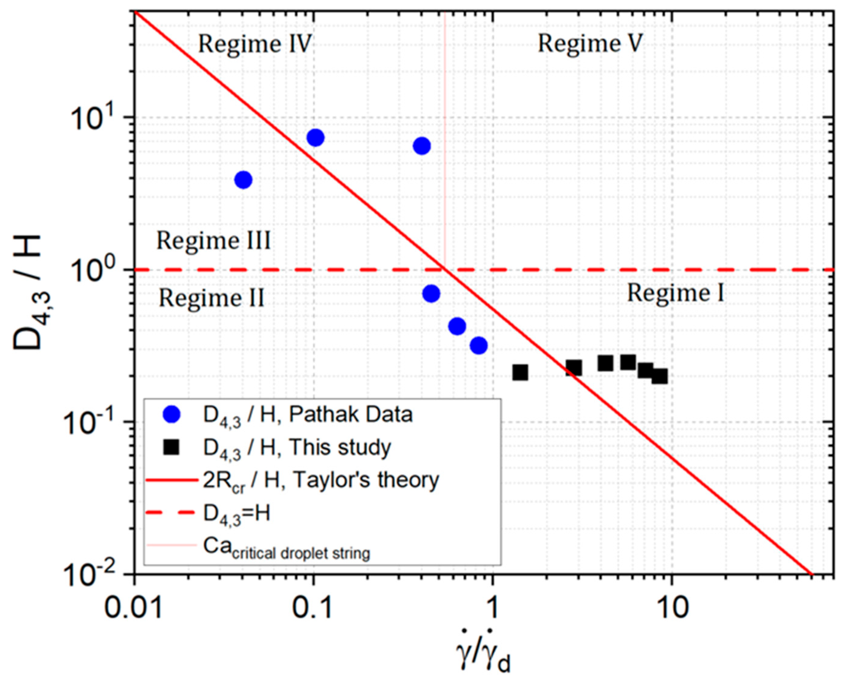
The probability of contact for drops inside the bands is highest, giving coalescence a potential role, while close neighbors modified the stress field about a drop, thus decreasing rupture. It is then plausible that the average diameter of drops grows to a value that would not be expected, taking into account a reduced model for the emulsion, and even more so if we compare it with the most straightforward system: Taylor’s model. However, a band of drops may impose a flow regime outside its core that is similar to that of a drop in the string of necklace form. Pathak’s observations [34] propose four regimes, shown in Figure 7. Pathak attempts to predict the possible morphologies in concentrated dispersions. The regimes’ classification is based on the dimensionless and normalized shear rate and the volumetric relation of the diameter of drops , where , [30]. The first regime corresponds to the capillary number of the drops exceeding the critical capillary, while the diameter of the drops is much less than the separation of the disks. The second regime corresponds to the case wherein the capillary number of drops is less than the critical capillary, and they are sufficiently dispersed such that no hydrodynamic interaction is relevant in relation to neighbors or walls. The third regime is the case of highly deformed drops (i.e., oblate ellipsoids). The fourth regime is the case where the capillary number of drops (based on Taylor’s model) is higher than the critical capillary, and the diameter of the drops is greater than the separation of the disks. In this regime, drops with a highly deformed shape—strings or necklaces– are present and provide a similar hydrodynamic environment to the banded structure of the emulsion. Moreover, the last regime (the fifth) is for the case where the diameter of the strings is below the separation of the disks, but the associated capillary number when strings are observed is less than the critical capillary of the strings in conditions of low confinement.
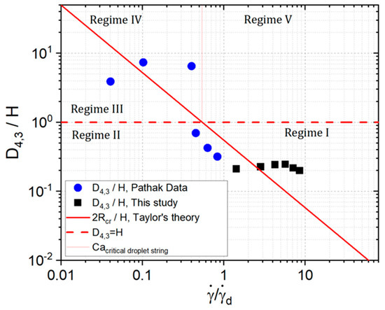
Figure 7.
Adaptation of Pathak’s representation of the regimes in the scenarios of concentrated emulsion morphologies [37]. Regime I corresponds to the case where the droplets are unstable, . Regime II corresponds to the case where the bulk droplets are stable, . Regime III corresponds to the case where the droplet diameter exceeds H, . Regime IV corresponds to the case where the droplet chains are unstable and break, and the capillary number of the chains is greater than the critical value. Regime V corresponds to unstable chains, , but unlike the previous regime, the capillary number of the droplet chains is lower than the critical value. The boundary, corresponds to unstable droplets and chains, this boundary at present is not completely clear [37]. In Taylor’s theory, the shear rate , predicts the maximum radius of the drops and the boundary corresponds to his predictions.
Figure 7 shows the droplet size distribution statistics for shear rates of 0.75, 1.5, 2.25, 3.0, 3.75, and 4.5 s−1 indicated by the data points (black squares) and described in more detail in [30]. Pathak’s data [37] correspond to the data (blue circles) points and also correspond to the behavior observed when an emulsion shows long strings. In principle, the results presented here correspond to Pathak’s first case where drops are agglutinated and unstable because they stretch and break. However, the detailed structure and possible flow consideration that may induce such spatial distributions have not been studied experimentally to the extent it has been consulted in the literature, which is significant.
These data clearly do not match, but under these conditions, both strings, like bands, present stability, which might occur due to the influence of the confinement of the effect of the walls (on the band or the strings). This confinement leads to the existence of large drops that overcome the rupture in both cases: Pathak with strings and the work presented in this paper with bands. These anisotropic structures are undoubtedly part of a transient state, which can be a consequence of deformations in bulk or in a concentrated emulsion.
The width of the bands is approximately measured directly from the images. The bands move in a centripetal direction (see Figure S5). The centripetal movement is a product of the accommodation of areas of higher viscosity and those of lower viscosity [38,39,40]. At present, it is not possible to propose a mechanism that explains this phenomenon.
5. Conclusions
The formation of bands perpendicular to the direction of the vorticity axis is not well understood [6,10,11,21,41,42]. The phenomenon of band formation is produced with relative simplicity, as is the case when mixing two immiscible Newtonian fluids with a low viscosity ratio , without surfactants, and for specific shear rate values [13]. A relatively plausible explanation is to attribute this to the competing effect of coalescence and rupture, wherein values of less than one of the coalescence predominate [27], and the formation of large drops of a size determined by the separation of the discs [14] will end in the formation of the pearl neck structures, as evidenced in the images [30] However, it is an open subject of study.
It is hypothesized that the curvature of the flow field has no significant role in the formation of bands, as posited by Caserta et al. [21,41]. Extrapolating the observations and taking as reference the work of Jeffrey Byars [39], it can be hypothesized that the observed bands correspond to a sector of an Archimedean spiral. We still cannot answer this question: whether these bands are concentric rings or spirals, and this quest was not part of the objectives of this paper.
However, here we show that a detailed analysis of the dynamics of the bands structures is possible, as well as the measurement of the flow field anomalies that are simultaneously observed. The local viscosity of the emulsion increases in areas with a higher concentration of drops, and regions of a lower concentration of drops imply a lower viscosity, which causes the morphology of the emulsion to change macroscopically.
Supplementary Materials
The following supporting information can be downloaded at: https://www.mdpi.com/article/10.3390/fluids8090240/s1, Figure S1: Scheme of the image analysis procedure for the description of the evolution of band formation. It is essential to include the flow direction with an arrow. The stacking of images correspond to the = 4.5 s−1; Figure S2: The z-project techniques for banding analysis. From left to right: average intensity, maximum intensity, minimum intensity, sum slices, standard deviation, and median; Figure S3: The plot of the intensity vs. radial distance graph of z-project techniques for banding analysis. From left to right: average intensity, maximum intensity, minimum intensity, sum slices, standard deviation, and median; Figure S4: Image obtained with the average intensity technique with color inversion (left side) and its graph of intensity vs. radial distance (px) for a (right plots). In the image of inverted colors, valleys correspond to a low population of drops and peaks to a high population of drops; Figure S5: Intensity vs. radial distance graph from to , each 0.75 (top to bottom). Formation and displacement of the bands. The intensity axis was normalized from 0 to 1; Figure S6: Plot the average intensity of 10 images (1 fps) for a . The parameters obtained from the adjustment of a Gaussian curve are indicated; Figure S7: Intensity vs. vorticity axis (μm) of a pack of 10 images (1 fps) for . Plot (a) shows the black trace for the mean intensity at each column, while red bands correspond to their uncertainties. Plots (b) and (d) correspond to raw intensities, while (c) and (e) to intensities with a baseline correction; Figure S8: On the left upper side is the graph of intensity vs. vorticity axis (μm) of a pack of 10 images (1 fps) for an applied . The mean time of t = 2410 s corresponds to the elapsed time from the start of the experiment to the capture of the image packet. The top and right graph corresponds to the peak position displacement observed for all 34 ministacks, i.e., vs. time for the two most significant peaks. On the lower side are the graph of FWHM and of intensity vs. time, respectively. Blue data points correspond to the rightmost peak and red point to the middle peak; Table S1: Data on the number of drops observed to determine the average band (and non-band) velocity for the .
Author Contributions
Conceptualization: J.E.L.M. and E.G.A.; methodology: J.E.L.M. and M.A.R.H.; formal analysis and investigation: J.E.L.M., M.A.R.H. and E.G.A.; writing—original draft preparation: J.E.L.M.; writing—review and editing: J.E.L.M. and E.G.A.; funding acquisition: F.M.L. and J.E.L.M.; resources: E.G.A.; supervision: M.A.R.H., E.G.A. and F.M.L. All authors have read and agreed to the published version of the manuscript.
Funding
This work was supported by the Dirección General de Asuntos del Personal Académico, DGAPA-UNAM [POSDOC-2020], the Departamento de Termofluidos-Facultad de Ingeniería-UNAM, and Instituto de Investigaciones en Materiales-UNAM. All of the above belong to the Universidad Nacional Autónoma de Mexico.
Data Availability Statement
The data that support the findings of this study are available from the corresponding author, J.E.L.M., upon reasonable request.
Acknowledgments
J.E.L.M. thanks the financing of the postdoc granted by DGAPA-UNAM 2020–2022. In addition, thank you to the Department of Thermofluids-Faculty of Engineering and the Materials Research Institute of the National Autonomous University of Mexico (UNAM) for the use of their laboratories and facilities.
Conflicts of Interest
The authors declare no conflict of interest relevant to the content of this article.
References
- Ciamarra, M.; Coniglio, A.; Nicodemi, M. Shear instabilities in granular mixtures. Phys. Rev. Lett. 2005, 94, 188001. [Google Scholar] [CrossRef] [PubMed]
- Vermant, J.; Solomon, M.J. Flow-induced structure in colloidal suspensions. J. Phys. Condens. Matter 2005, 17, R187. [Google Scholar] [CrossRef]
- Highgate, D. Particle migration in cone-plate viscometry of suspensions. Nature 1966, 211, 1390. [Google Scholar] [CrossRef]
- Mao, C.; Huang, Y.; Qiao, Y.; Zhang, J.; Kong, M.; Yang, Q.; Li, G. Vorticity-Aligned Droplet Bands in Sheared Immiscible Polymer Blends Induced by Solid Particles. Langmuir 2020, 36, 4383–4395. [Google Scholar] [CrossRef] [PubMed]
- Wychowaniec, J.K.; Iliut, M.; Borek, B.; Muryn, C.; Mykhaylyk, O.O.; Edmondson, S.; Vijayaraghavan, A. Elastic flow instabilities and macroscopic textures in graphene oxide lyotropic liquid crystals. NPJ 2D Mater. Appl. 2021, 5, 1–10. [Google Scholar] [CrossRef]
- Van Der Gucht, J.; Lemmers, M.; Knoben, W.; Besseling, N.; Lettinga, M. Multiple shear-banding transitions in a supramolecular polymer solution. Phys. Rev. Lett. 2006, 97, 108301. [Google Scholar] [CrossRef]
- Lerouge, S.; Berret, J.-F. Shear-Induced Transitions and Instabilities in Surfactant Wormlike Micelles. In Polymer Characterization: Rheology, Laser Interferometry, Electrooptics; Dusek, K., Joanny, J.-F., Eds.; Springer: Berlin/Heidelberg, Germany, 2010; pp. 1–71. [Google Scholar]
- Caiazza, C.; Preziosi, V.; Tomaiuolo, G.; O’Sullivan, D.; Guida, V.; Guido, S. Flow-induced concentration gradients in shear-banding of branched wormlike micellar solutions. J. Colloid Interface Sci. 2019, 534, 695–703. [Google Scholar] [CrossRef]
- Olmsted, P.; Lu, D.; Null, C. Phase coexistence of complex fluids in shear flow. Faraday Discuss. 1999, 112, 183–194. [Google Scholar] [CrossRef][Green Version]
- Olmsted, P.D. Perspectives on shear banding in complex fluids. Rheol. Acta 2008, 47, 283–300. [Google Scholar] [CrossRef]
- Fielding, S. Complex dynamics of shear banded flows. Soft Matter 2007, 3, 1262–1279. [Google Scholar] [CrossRef]
- Amis, E.; Fanconi, B. Polymers Division 2000 Programs and Accomplishments; NIST Interagency/Internal Report (NISTIR); National Institute of Standards and Technology: Gaithersburg, MD, USA, 2001. [Google Scholar]
- Migler, K. String formation in sheared polymer blends: Coalescence, breakup, and finite size effects. Phys. Rev. Lett. 2001, 86, 1023. [Google Scholar] [CrossRef]
- Salmon, J.; Manneville, C.; Molino, S.; Null, F. Velocity profiles in shear-banding wormlike micelles. Phys. Rev. Lett. 2003, 90, 228303. [Google Scholar] [CrossRef]
- Simeone, M.; Sibillo, V.; Tassieri, M.; Guido, S. Shear-induced clustering of gelling droplets in aqueous biphasic mixtures of gelatin and dextran. J. Rheol. 2002, 46, 1263–1278. [Google Scholar] [CrossRef]
- Montesi, A.; Peña, A.; Pasquali, M. Vorticity alignment and negative normal stresses in sheared attractive emulsions. Phys. Rev. Lett. 2004, 92, 58303. [Google Scholar] [CrossRef] [PubMed]
- Divoux, T.; Fardin, M.A.; Manneville, S.; Lerouge, S. Shear banding of complex fluids. Annu. Rev. Fluid Mech. 2016, 48, 81–103. [Google Scholar] [CrossRef]
- Briole, A.; Casanellas, L.; Fardin, M.-A.; Py, C.; Cardoso, O.; Browaeys, J.; Lerouge, S. Shear-banding fluid (s) under time-dependent shear flows. Part II A Test of the Moorcroft–Fielding Criteria. J. Rheol. 2021, 65, 1201–1217. [Google Scholar] [CrossRef]
- Osuji, C.; Weitz, D. Highly anisotropic vorticity aligned structures in a shear thickening attractive colloidal system. Soft Matter 2008, 4, 1388–1392. [Google Scholar] [CrossRef] [PubMed]
- Schall, P.; Van Hecke, M. Shear bands in matter with granularity. Annu. Rev. Fluid Mech. 2010, 42, 67–88. [Google Scholar] [CrossRef]
- Caserta, S.; Guido, S. Vorticity Banding in Biphasic Polymer Blends. Langmuir 2012, 28, 16254–16262. [Google Scholar] [CrossRef]
- Pathak, J.; Davis, M.; Hudson, S.; Migler, K. Layered droplet microstructures in sheared emulsions: Finite-size effects. J. Colloid Interface Sci. 2002, 255, 391–402. [Google Scholar] [CrossRef][Green Version]
- Lee, L.L.; Niknafs, N.; Hancocks, R.D.; Norton, I.T. Emulsification: Mechanistic understanding. Trends Food Sci. Technol. 2013, 31, 72–78. [Google Scholar] [CrossRef]
- Schuch, A.; Leal, L.G.; Schuchmann, H.P. Production of W/O/W double emulsions. Part I: Visual observation of deformation and breakup of double emulsion drops and coalescence of the inner droplets. Colloids Surf. A Physicochem. Eng. Asp. 2014, 461, 336–343. [Google Scholar] [CrossRef]
- Grace, H. Dispersion phenomena in high viscosity immiscible fluid systems and application of static mixers as dispersion devices in such systems. Chem. Eng. Commun. 1982, 14, 225–277. [Google Scholar] [CrossRef]
- De Bruijn, R. Tipstreaming of drops in simple shear flows. Chem. Eng. Sci. 1993, 48, 277–284. [Google Scholar] [CrossRef]
- Bentley, B.; Leal, L. An experimental investigation of drop deformation and breakup in steady, two-dimensional linear flows. J. Fluid Mech. 1986, 167, 241–283. [Google Scholar] [CrossRef]
- Jansen, K.; Agterof, W.; Mellema, J. Droplet breakup in concentrated emulsions. J. Rheol. 2001, 45, 227–263. [Google Scholar] [CrossRef]
- Karam, H.; Bellinger, J. Deformation and breakup of liquid droplets in a simple shear field. Ind. Eng. Chem. Fundam. 1968, 7, 576–581. [Google Scholar] [CrossRef]
- Leiva, J.M.; Geffroy, E. Evolution of the size distribution of an emulsion under a simple shear flow. Fluids 2018, 3, 46. [Google Scholar] [CrossRef]
- Luciani, A.; Champagne, M.F.; Utracki, L.A. Interfacial tension coefficient from the retraction of ellipsoidal drops. J. Polym. Sci. Part B Polym. Phys. 1997, 35, 1393–1403. [Google Scholar] [CrossRef]
- Derkach, S.R. Rheology of emulsions. Adv. Colloid Interface Sci. 2009, 151, 1–23. [Google Scholar] [CrossRef]
- Vananroye, A.; Van Puyvelde, P.; Moldenaers, P. Effect of confinement on droplet breakup in sheared emulsions. Langmuir 2006, 22, 3972–3976. [Google Scholar] [CrossRef]
- Sundararaj, U.; Macosko, C. Drop breakup and coalescence in polymer blends: The effects of concentration and compatibilization. Macromolecules 1995, 28, 2647–2657. [Google Scholar] [CrossRef]
- Taylor, G. The viscosity of a fluid containing small drops of another fluid. Proc. R. Soc. Lond. A 1932, 138, 41–49. [Google Scholar]
- Taylor, G. The formation of emulsions in definable fields of flow. Proc. R. Soc. Lond. A 1934, 146, 501–524. [Google Scholar]
- Pathak, J.; Migler, K. Droplet–String Deformation and Stability during Microconfined Shear Flow. Langmuir 2003, 19, 8667–8674. [Google Scholar] [CrossRef]
- Mckinley, G.; Öztekin, A.; Byars, J.; Brown, R. Self-similar spiral instabilities in elastic flows between a cone and a plate. J. Fluid Mech. 1995, 285, 123–164. [Google Scholar] [CrossRef]
- Byars, J.; Öztekin, A.; Brown, R.; Mckinley, G. Spiral instabilities in the flow of highly elastic fluids between rotating parallel disks. J. Fluid Mech. 1994, 271, 173–218. [Google Scholar] [CrossRef]
- Choi, S.; Schowalter, W. Rheological properties of nondilute suspensions of deformable particles. Phys. Fluids 1975, 18, 420–427. [Google Scholar] [CrossRef]
- Caserta, S.; Simeone, M.; Guido, S. Shear banding in biphasic liquid-liquid systems. Phys. Rev. Lett. 2008, 100, 137801. [Google Scholar] [CrossRef]
- Wilkins, G.; Olmsted, P. Vorticity banding during the lamellar-to-onion transition in a lyotropic surfactant solution in shear flow. Eur. Phys. J. E 2006, 21, 133. [Google Scholar] [CrossRef]
Disclaimer/Publisher’s Note: The statements, opinions and data contained in all publications are solely those of the individual author(s) and contributor(s) and not of MDPI and/or the editor(s). MDPI and/or the editor(s) disclaim responsibility for any injury to people or property resulting from any ideas, methods, instructions or products referred to in the content. |
© 2023 by the authors. Licensee MDPI, Basel, Switzerland. This article is an open access article distributed under the terms and conditions of the Creative Commons Attribution (CC BY) license (https://creativecommons.org/licenses/by/4.0/).


