1. Introduction
The analysis of flows with an irregular (Mach) reflection of shock waves is important in the gas-dynamic design and optimization of supersonic air intakes, nozzles, jet apparatus, launch complexes, as well as in the development of blast technologies and means of suppressing the damaging effect of an explosion [
1]. According to [
1,
2,
3], various flow parameters (stagnation pressures, velocities, dynamic pressures, etc.) in flow regions separated by a slipstream issuing from the triple point of Mach reflection can differ significantly. It can determine the design of gas-dynamic devices. For example, the idea of a new combined ramjet engine was proposed and theoretically substantiated in [
4,
5,
6]. According to this concept, the gas flow behind the reflected shock
(in region 2 in
Figure 1a), which has a significantly higher total pressure than the flow behind the main (Mach) shock
(in region 3), can be used in the thermodynamic cycle of a classic ramjet engine. At the same time, the flow behind the main shock has a significantly higher temperature, especially at high supersonic speeds, which can initiate the detonation of the gas mixture, thus it can be used in the thermodynamic cycle of a detonation engine. For the successful separation of two streams behind the triple point
T of the Mach reflection, it is important to determine the height triple point
and shape
of the slipstream
that emanates from it, as well as the shape and size of all other discontinuities in the flowfield.
One of the first approximate analytical models of a planar supersonic flow with Mach reflection was formulated in [
7]. Within the framework of this model, it was reasonably assumed [
8] that the flow in region three forms a so-called “virtual nozzle” with subsonic flow acceleration behind the shock
up to the critical sound speed (
) in the narrowest section (
CC’ in
Figure 1b). The acceleration to the critical speed must coincide with the turn of the slipstream
in the horizontal direction (the angle of flow
in point
C) under the influence of a rarefaction wave
that falls from the trailing edge of the wedge (
Figure 1a), or from the jet boundary (
Figure 1b), or formed in some other way. However, it was unreasonably assumed in [
7] that the slipstream
is rectilinear, and the critical section of the “virtual nozzle” three corresponds to the point of incidence of the first characteristic
BD of the rarefaction wave
. It led to large (up to 50–90%) errors in determining the height of the triple point and other flow parameters. The application of the Grib–Ryabinin model [
9] to region two of the supersonic flow, carried out in [
10], led to a slight refinement of the results with a simultaneous complication of the mathematical model.
The analytical model proposed in [
11] and detailed in [
12,
13] for flows in supersonic jets and narrowing channels considers flow region two as a simple Prandtl–Meyer rarefaction wave conjugated with region three by the condition of equality of pressures on the sides of an upwardly convex slipstream
[
14]. Taking into account the variation in the angle
of the inclination of the slipstream significantly improves the accuracy of calculations of the supersonic part of the flow (as shown in [
11,
12,
13], the error in determining the height of the triple point is about 0.5–2% compared to the results of calculations of the supersonic part of the flow by the method of characteristics). The opposite turn of the slipstream is carried out on its final segment
DC. It can be based on the solution of the problem of the incidence of the rarefaction wave
on the slipstream.
Interest in methods for rapid estimation of the parameters of the shock-wave structure of planar flows with Mach reflection, including asymmetric ones [
15,
16,
17], has noticeably increased recently [
15,
16,
17,
18]. This fact can be associated with the development of aviation and rocket technology, flying at high supersonic speeds in the atmosphere.
The presence of strong shock waves in a supersonic flow of a reactive gas (fuel–air gaseous mixture) can initiate chemical reactions and detonation effects. In this regard, it is necessary to generalize the approximate analytical models [
11,
12,
13], which have proven themselves well for the flows of a perfect non-reacting gas, to the case of a change in the chemical composition and pulsed energy release on emerging shocks. In [
19,
20,
21], the classical shock-wave relations are generalized to the case of a change in the chemical composition and the impulse energy efflux within the framework of Chapman–Jouguet stationary detonation theory. In particular, “detonation” polars have been constructed instead of classical shock polars [
19,
20,
21]; generalized criteria for regular or Mach shock reflection transition were derived, and their shift compared to the flow without energy supply and change in chemical composition was analyzed.
The numerical and theoretical results achieved in [
19,
20,
21,
22,
23] are not always directly applicable in practice. In particular, the important analytical relations obtained in [
19] are based on the assumption of the presence of detonation effects on both the incident (
) and main (
) shocks. At the same time, as it was shown in [
5,
6], it is a noticeably higher temperature of the gas mixture downstream from the main shock that initiates detonation (see also
Figure 2). At the same time, neither a change in the chemical composition nor the energy release is observed on the incident shock or the reflected one. It is taken into account in study [
20], where, however, to describe the flow on the main shock, the average (between the initial mixture and its combustion products) adiabatic index was introduced, but the mechanism of its calculation was not explained. The calculation of the chemical kinetics of initiated reactions [
22,
23] also does not assist the development of an approximate analytical technique for fast calculations.
This study generalizes the approximate analytical flow model with Mach reflection [
11,
12,
13] to the case of a change in the chemical composition of the gas mixture and a pulsed energy supply at the main shock. On the example of a highly overexpanded jet of a methane–air mixture, we present an algorithm for calculating the parameters of the shock wave structure. The primary results of its application are shown, and a comparison is made with similar data for a highly overexpanded jet of non-reacting gas.
2. Model and Methods
2.1. Calculation of Parameters in Vicinity of the Triple Point
When a sufficiently strong oblique shock wave
reflects in a flow with the Mach number
, a triple configuration of the second type (TC-2) according to the classification [
24,
25] forms at the triple point
T. The parameters of the shocks
are related by the following conditions of equality of static pressures and co-directionality of flows across a slipstream
:
Here,
,
, and
are the strengths of incident shock (
), the reflected one (
), and the main one (Mach stem
), i.e., the ratios of static pressures on their sides. Additionally,
is the static pressure in the incoming stream,
are the pressures behind the shocks
, and
are the flow deflection angles on those shocks in the vicinity of the triple point related to corresponding shock strengths:
on the incident shock and the reflected one [
25], and by the relation [
19]
for the Mach stem. Here,
,
is the adiabatic index of the gas mixture in the incoming stream, and
is the adiabatic index of the combustion products behind the Mach shock. Dimensionless quantity
characterizes the pulse energy supply; the values of density
, temperature
, isobaric specific heat
, and released heat
(specific heat of combustion) are the parameters of the incoming stream.
The Mach numbers behind the incident and reflected shocks obey the relations
Classical relations based on the Chapman–Jouguet theory of stationary detonation wave are,
where the indices “
” and “
” mean the velocity components normal and tangential to shock surface, and we determine the Mach number
in the vicinity of the triple point:
Here
is shock slope angle to flow direction upstream it, and
is the inverse ratio of the gas densities on the sides of the shock. At
and
, it reduces to the ordinary Rankine–Hugoniot adiabat.
As shown in [
20], a sufficiently large, pulsed energy supply
displaces the “detonation” polar III (
Figure 3), which obeys the relation (5), inside the shock polar I, corresponding to Equation (3). As it is seen from
Figure 3, the strength of the steady Mach stem must belong to the interval
Here, the value
corresponds to a direct shock wave with pulsed energy supply, and the triple configuration with
and
(
Figure 3) corresponds to an analogue of the von Neumann criterion [
25,
26] of shock reflection transition. Shock strengths
and
are obey the relations [
23]
The only solution of the system (1-2) in the considered range of sufficiently large Mach numbers exists in the range of incident shock strengths
Here, the value
corresponds to the limiting position of polar IIb of the reflected shock (its contact with polar III, see
Figure 3). The flow behind the reflected shock
is always supersonic (
), while the flow behind the main shock
is subsonic (
).
As a rule [
7,
10,
11,
12,
13,
15,
16,
17,
18] for an approximate analytical description of the flow in region 3 (
Figure 1a,b), a model of a quasi-one-dimensional flow with some initial Mach number
directly downstream from the main shock is used. The value
can be determined by Formula (9), then
, or a similar relation for
, which corresponds to the flow at point N (
Figure 1) behind the direct shock (then
), or the half-sum of these values. Then
Corresponding to the approach adopted in [
13,
18]. The value of
also can be based on more complex methods for flow parameters averaging [
7,
27]. Furthermore, we use approximation (13) to determine the initial Mach number of the flow along “virtual nozzle” 3.
Thus, the application of the proposed model makes it possible to establish the initial values of the flow angle () and Mach numbers ( and ) in regions 2 and 3 behind the reflected and main shocks.
It is necessary to add that energy supply should not be taken into account immediately at surface of the Mach stem, following the more advanced classical Zel’dovich–von Neumann–Döring (ZND) theory. Thus, solving the problem (1–2) at the triple point, we should use a relation similar to (3, 4) instead of (5) for the flow deflection angle at the shock
and a relation similar to (7, 8) instead of (9) for Mach number after it. In this approach, “detonation” polar III in
Figure 3 coincides with ordinary shock polar I, and the problem in the triple point is to be solved as an ordinary problem of Mach reflection in the non-reacting gas.
After it, according to ZND theory, a thin layer of chemical reactions initiated by high temperature after the Mach stem
follows just after that shock. The static pressure drop after the Mach stem accompanies that chemical reaction, forming a so-called “von Neumann peak” or a “himpik” (as it is called in Soviet or post-Soviet literature). Vertical distance between “strong” upper branches of the polars I and III in
Figure 3 characterizes that pressure drop from the “Hugoniot” parameters that corresponds to Mach reflection in non-reacting gas to the parameters that approximately correspond to Chapman–Jouguet theory applied in this study. Modernizing the proposed approximate analytical model, it is possible to take into account finite-rate kinetics downstream from the Mach stem. However, as the chemical reaction zone is very thin (about 10
−4 m in typical considering conditions [
28]), comparing with typical lengths in this study (such as channel width and Mach stem height), it seems admissible to compress that layer into alone surface of the shock
and apply the Chapman–Jouguet theory to that shock immediately.
2.2. Flow in a Rarefaction Wave behind a Reflected Shock
Relations for flow direction angle
of flow in the Prandtl–Meyer wave two with rectilinear acoustical characteristics of the first family
here,
is the Prandtl–Meyer function, together with the conditions,
,
is the isentropic flow rate function, and the equality of pressures across the slipstream
are written in the form
here,
and
are the isentropic pressure functions written for gases above and below the slipstream, leading to the following equations for the shape
of the slipstream
and the change in flow properties on its sides:
Considering the Mach number
below the slipstream as an independent variable, we use Equation (14) obtain the forms
With the same chemical composition of flows on both sides of slipstream
, relations (14) and (15) take the simplified form known from [
13,
14]. Equations (14) or (15) are integrated up to the point
D of intersection of the slipstream
with the boundary characteristic
BD of the second family, which falls from the exit point of the reflected shock
(
TB) on the jet boundary (
Figure 1b). The flow below the slipstream must remain subsonic (
); the achievement of critical sound velocity indicates that the proposed triple point height is significantly underestimated.
Calculations show that the angle of turn of a slipstream in the
TD section is usually small in its absolute value, but it can be 1.5–2 times greater than the initial angle
of the slipstream’s inclination at the triple point. Therefore, ignoring the curvature of the slipstream [
7] leads to a significant underestimation of the obtained height
of the main shock.
An analysis of the differential characteristics of the flow in the Prandtl–Meyer wave, similar to that carried out in [
13,
14] at
, leads to the following equations for determining the shape
of the curvilinear boundary acoustic characteristic
BD of the second family and flow parameters along the direction
of its incidence:
Here,
is the Mach angle;
is flow Mach number at an arbitrary point on the characteristic
BD; and
is the Mach number of the flow on the other side of the slipstream
at the point
of its intersection with the corresponding rectilinear characteristic
. The coordinate
obeys the formula
and the distance
from this point to the envelope of the family of rectilinear characteristics can be calculated by such a way:
The integration of the system (16) starts from point
B of the intersection of the reflected shock with the jet boundary and ends at point
D of the intersection of the characteristic
BD with the slipstream. If we take the distance
L between the curved characteristic
BD and the slipstream as an independent variable, then Equation (16) obtains the forms
The value
characterizes the decrease in the distance
L as the curvilinear characteristic
BD approaches the slipstream. Equation (17) should be integrated starting from the value
L = |B1B|, which is the initial distance between the characteristic
BD and the slipstream, and the flow parameters correspond to point
B behind the reflected shock to the value
L = 0 at point
D of intersection of the slipstream and the characteristic
BD.
When taking into account finite-rate kinetics (for example, in classical ZND theory), corresponding elements should be introduced into model of flow in zone III (especially just after the Mach stem). Though the zone of chemical reactions is very thin, its introduction into the proposed model can be a subject of further studies.
2.3. Shape and Parameters of the Reflected Curved Shock
It has been repeatedly shown [
29,
30] that the reflection coefficient of rarefaction or compression disturbances that overtake the previous oblique shock is very small (if the flow behind the shock is not transonic, which is not the case now). In addition, the intensity of the rarefaction wave acting on the reflected shock
in the triangle
TBB1 (
Figure 1b) is small in itself. Therefore, we apply the method first proposed in [
31], and the shape of the reflected shock is determined based on the condition of flow direction conjugation (i.e., the flow angles behind each point of the reflected shock
and at the corresponding points of the Prandtl–Meyer expansion wave 2 must coincide). The analysis of the differential characteristics of the flowfield in wave 2 [
13,
14], together with the conditions on the oblique shock, determine the shape of the reflected shock in polar coordinates (
,
):
Here,
is the distance from the nozzle edge to the considered point on the shock,
is the polar angle measured from the horizontal direction (see
Figure 1b), and
is the Mach angle. Flow deflection angle
on the reflected shock depends on shock strength
:
and the shock slope angle
obeys the dependence
The Mach number
at the corresponding point of the rarefaction wave behind the shock is determined by the relation
Here,
is the Prandtl–Meyer function. The corresponding Mach number
on the other side of the slipstream obeys the relation
The curvature of the streamline
, which is present in (19) behind an arbitrary point on shock surface, is defined as follows:
Here, is the ordinate of a given point behind the shock, is the flow angle at this point, , , and is the half-width of the nozzle exit section.
Equations (18) and (19) are to be integrated from the value at the triple point T to the value at point B of the shock exit to the jet boundary with subsequent reflection of the rarefaction wave .
Our calculations, according to (18–19), demonstrate that the geometrical curvature of the reflected shock is usually almost negligibly small (its slope angle diminishes on 0.1–0.3°). When applying any finite-rate kinetics model (as in classical ZND approach), a small segment of relatively large curvature of the reflected shock (TB) is present in the vicinity of the triple point T. At this segment, reflected shock strength quickly diminishes from “Hugoniot” parameters to “Chapman-Jouguet” ones under the influence of pressure drop in von Neumann peak after the Mach stem. In our model, the initial parameters of the reflected shock are directly predicted by Chapman–Jouguet theory, and the influence of the finite rate of the chemical reaction is subject to further studies and comparisons.
2.4. Incidence of a Rarefaction Wave on a Slipstream
Many modern approximate models of flows with Mach reflection [
15,
16,
17] actually replace a fast analytical assessment of the interaction of a rarefaction wave
(
Figure 1a,b) with a slipstream
with a calculation by the method of characteristics. However, on the other hand, the reduction in the
DCE region of this interaction to a single point
D, ignoring the finite length of the interval
DC of the slipstream turn in the horizontal direction [
7,
10], also leads to significant errors in determining the parameters of the shock-wave structure.
By analogy with the model [
11,
12,
13], the analysis of the interaction of a wave with a slipstream is carried out as follows. It is assumed that the Prandtl–Meyer flow is realized in the wave, and the Mach number
of the flow in front of this wave corresponds to the average slope of the characteristic
BD in region 2:
The initial Mach number in flow region 3 and the width of this “virtual nozzle” are determined from the previously obtained calculations of the shape of the slipstream in the section TD, the boundary characteristic BD, and the variation in the flow parameters along them.
An arbitrary Mach number
on the lower side of the slipstream corresponds to the Mach number
on its upper side according to the relation
and the width
of area 3 is such that
In this case, the abscissa
of the point
H is approximately determined from the condition of straightness of the voluntary incident characteristic
BH1H:
Here,
. Slope
of the slipstream at this point obeys the condition
which takes into account the flow deflection in the waves incident on the slipstream
and
reflected from it. Here,
is the Mach number on the
BH1 characteristic, and
is the previously determined slope of the slipstream at point
D.
The integration of the system (21-24) determines the shape of the slipstream . It is carried out until Mach number value below the slipstream reaches unity.
If the rarefaction wave
experiences refraction on a reflected shock
(see, for example,
Figure 1a) before falling onto a slipstream, we apply the analytical solutions for the oblique shock–rarefaction fan interaction, obtained in [
32,
33].
2.5. Algorithm of Application of Our Generalized Approximate Analytical Model
To quickly estimate the parameters of the shock-wave structure of a supersonic flow with a Mach reflection, a pulsed energy supply, and a change in the chemical composition on the main shock, first of all, the flow parameters of the initial gas mixture (values and ), as well as the adiabatic index of the combustion products, the dimensionless pulsed energy supply , and the strength of the incident shock, which satisfies inequality (12), should be given. Further, the flow parameters are determined as follows:
Using the relations (1–7), we calculate the flow parameters in the vicinity of the triple point. Relations (2), (8), (9), and (13) determine the Mach numbers and on both sides of the slipstream, the initial Mach number of the flow along “virtual nozzle” 3, and the angle of the slipstream inclination in the vicinity of the triple point.
The value of the height of the triple point in the first approximation should be set.
Relations (18–19) establish the shape of a slightly curved (upwards–convex) reflected shock wave (TB), as well as the coordinates of point B and the flow parameters behind the shock at this point.
Simultaneously, the shape of the boundary characteristic BD (16–17), the slipstream (15), and the flow parameters along them should be determined. The integration of Equations (15)–(17) ends at point D of intersection of the boundary characteristic BD with a slipstream. The flow along “virtual nozzle” 3 can reach the critical velocity () up to this point. It indicates a significant decrease in the value in the accepted approximation.
The problem (20–25) of the reversal of the slipstream under the influence of the rarefaction wave is being solved. If it is found that the critical flow velocity in area 3 is reached before slipstream turns to the horizontal direction ( at ), the proposed height is too small; otherwise, it is excessive.
According to the results of the iteration, we refine the value of Mach stem height, and the calculations should be made in the next approximation, returning to point 2.
3. Results of the Application of the Approximate Analytical Model
As an example of the application of the presented model, the outflow of a uniform (in the exit section) planar jet of a fuel–air gas mixture is calculated. The adiabatic indices of upstream flow and the gas mixture behind the main shock were taken equal, correspondingly, to
and
. They approximately corresponded to the stoichiometric methane–air mixture (the mass fractions were 4.856% CH
4, 74.212% N
2, 19.980% O
2, 0.951% of other impurities) and the products of its complete combustion, including carbon dioxide gas and water vapor. The specific heat of combustion of the fuel was assumed to be 55.266 MJ/kg, which corresponded to the value of
MJ/kg in terms of the entire gas mixture and the dimensionless value of the pulsed energy supply (6)
at T = 300 K. This value of the dimensionless specific energy supply was much greater than that considered in [
19].
Due to the large sudden energy supply, the solution of system (1-2) with restrictions (1–7), which describes the stationary Mach reflection, existed only at
. According to condition (11), which limited the range of the possible strength of the main shock at
, the detonation polar III (
Figure 3) is compressed to the point
and it disappears at lower Mach numbers. In such a case, the solution describing the triple configuration of the Mach reflection should be sought, admitting the propagation of the main shock (detonation) wave
upstream from the incoming flow.
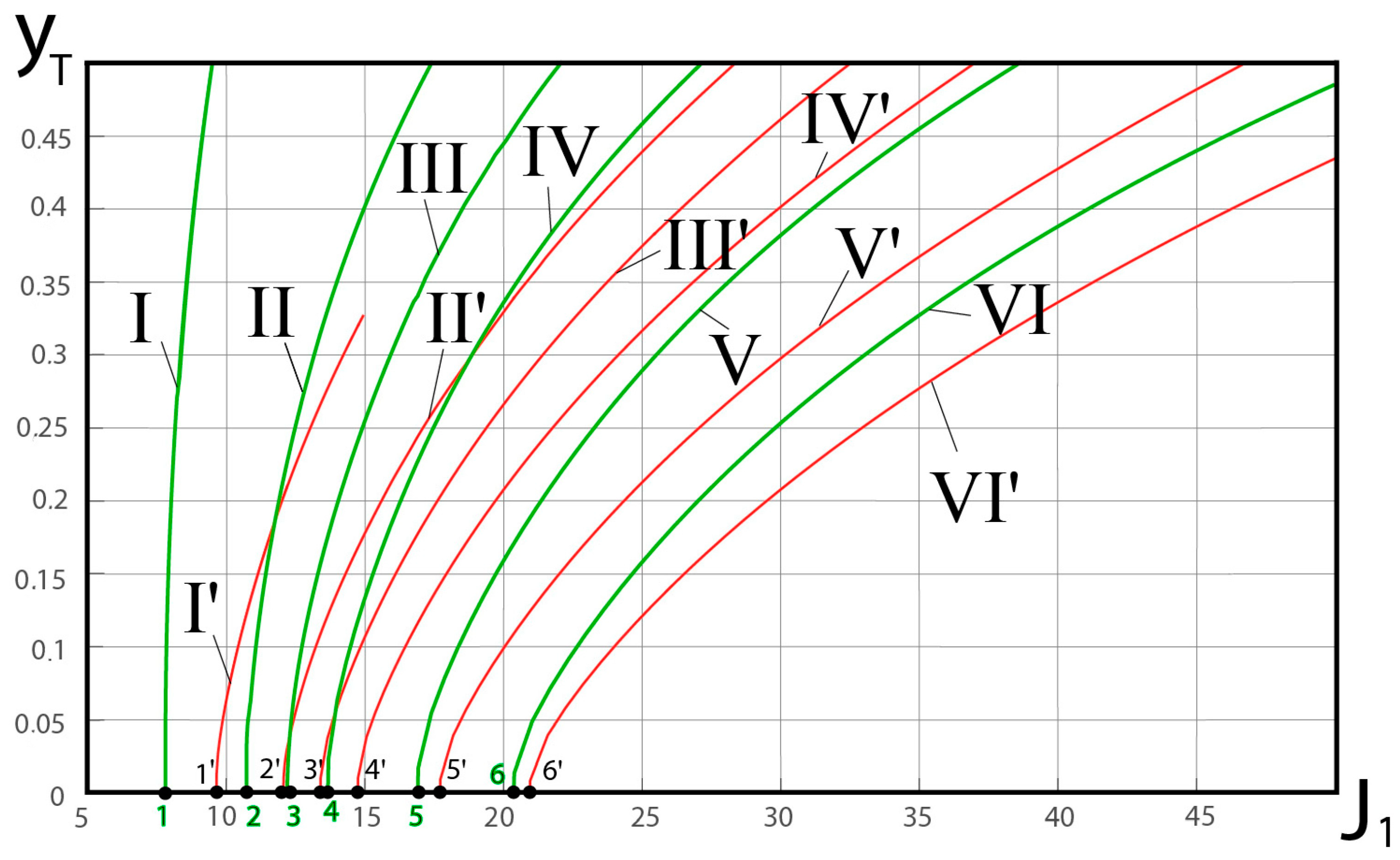
Examples of calculation of the dimensionless (referred to the half-width of the exit section) height of the triple point
, depending on the incident shock strength (provided that the considered strongly overexpanded jet flows out without separation), is shown in
Figure 4. Curves I–VI correspond to Mach numbers
M = 6, 6.5, 7, 8, 9, and 10 in the entire range (12) of theoretically possible incident shock strengths.
For comparison, curves I’–VI’ show the values of
calculated for the same flow parameters but without the energy release (
) and changes in chemical composition of the gas mixture (
), i.e., according to the algorithm [
11,
12,
13], a generalization of which is presented in this paper. From a comparison of curves I–VI and I’–VI’, it is obvious that a significant pulsed energy supply significantly shifts the conditions of transition to the Mach reflection (from points 1′–6′, which correspond to “classical” von Neumann criterion, to points 1–6). In addition, the energy release leads to a significant increase in the size of the main (Mach) shock and the width of the subsonic flow region behind it.
The next example of the application of the proposed approximate analytical model relates to
Figure 2. The planar flow of the stoichiometric methane–air gas mixture in the narrowing channel between two wedges was studied numerically using the ANSYS Fluent 2020 R2 CFD software package (academic version). It was admitted that the wedge angle
, which is also flow deflection angle on the incident shock; the distance between two front edges is equal to 200 mm, and the minimal width of the channel is equal to 100 mm. The inflow had normal atmospheric parameters (static pressure and temperature), its dynamic viscosity obeyed the Sutherland law, and ordinary
SST model of turbulence was applied. In one approach, the finite-rate model was applied to the calculations of the kinetics of chemical reactions initiated by high static temperature downstream from the Mach stem. In another approach, chemical reactions were artificially “switched off”, and no variations in chemical composition of the mixture occurred. The unstructured numerical grid contained about 2·10
6 cells. Calculated dimensionless (referred to the width of the entrance section) heights
were approximately equal to 0.377 and 0.207 in flows with present and artificially absent chemical reactions, correspondingly. The first calculated example (at presence of chemical reactions) is demonstrated in
Figure 2a,b. It can be also seen in
Figure 2b that chemical reactions are initiated only downstream from the main shock but not after the incident shock and the reflected one (generally, products of combustion, such as carbon dioxide, are present only in flow region after the Mach stem).
Our approximate approach to this flow, which includes also the model of oblique shock–expansion fan interaction derived in [
32,
33], gives us
in the first case and
in the second one. Thus, the comparison between numerical and analytical results seems quite satisfactory.
At the next stage, we provided a comparison of our analytical model with results of numerical experiment in [
34]. At first, the flow of a lean hydrogen air mixture (0.4 H
2 + 4.772 Air) was studied from the upstream Mach numbers
M = 3.0 and
M = 3.15. Such a problem had no steady numerical solution with the Mach reflection in [
34] (transition to regular reflection occurred, or auto-oscillations of Mach stem with detonation downstream started). We presumed the full combustion of hydrogen (its specific heat of combustion could be estimated as 55.266 MJ/kg, thus
MJ/kg was the energy supply per unit mass of gas mixture. It caused the energy efflux to exceed the critical value, which was equal to 0.538 MJ/kg at
M = 3.15 and 0.477 MJ/kg at
M = 3.0. At those values, the detonation polar for the Mach stem compressed into a single point and disappeared, thus there was no solution for stationary detonation (at least at
and
, which were adiabatic indices of gas mixtures upstream from the shock and downstream from it). Thus, the coincidence between analytical and numerical results was also obtained, though it was a negative one. A more positive coincidence for that gas mixture can be obtained, for example, at
M = 4.0 (stationary solutions exist there, and reasonable results can be provided).
At the last stage, the flow of a stoichiometric hydrogen–oxygen mixture (2 H
2 + O
2) was considered. We analyzed a supersonic jet flow of a gas mixture with chemical parameters and a Mach number similar to the number considered in [
34]. At
M = 4.0, the energy supply also exceeded the critical value, thus it is not a wonder that only unsteady flow regimes were obtained in [
34] at
.
At
M = 7.0, the stationary detonation was computationally obtained in [
34] only within a small range of flow deflection angles at the incident shock (between
and
). The upper limit completely obeys our theory (maximal value
that corresponds to shock polar IIb in
Figure 3 is to be obtained at
). According both to the numerical experiment in [
34] and to our model, the Mach stem occupies almost all of the cross-section of the nozzle or the narrowing channel at
.
The lower limit (
) in [
34] quite corresponds to the “classical” von Neumann criterion of shock reflection transition (
). Our theory diminishes the lower limit of Mach reflection to
(one can compare points 1 and 1′ in
Figure 5). It is difficult to determine which criterion is more correct in practice because that range of flow deflection angles belongs to so-called dual solution zone (up to
, according to classic theory for perfect gas, [
26]), and we cannot answer whether the Mach reflection or the regular one is realized. At least, our computations demonstrate the regular reflection even at
, though the Mach stem size at the Mach reflection of such an incident shock should be sufficiently large. Moreover, chemical reactions began at
M = 7.0 and
M = 8.0, even downstream from the incident shock and not only after the Mach one.
Dependencies
of the Mach stem height on flow deflection angle on the oblique shock that falls onto the symmetry plane in supersonic jet flow are shown in
Figure 5 for both “detonation” and “non-detonation” cases at
M = 7.0 (curves I and I’) and
M = 8.0 (curves II and II’).


