Abstract
The transverse flow-induced vibration (FIV) of an elastically-supported cylinder-plate assembly (viz., a rigid splitter-plate attached to the downstream side of a circular cylinder) with a low mass ratio of 10 and zero structural damping is investigated using numerical simulations at a Reynolds number of 100. The structural oscillations and characteristics of the flow around the structure are analyzed in terms of the vibration characteristics and the fluid forces as a function of the plate length LSP and the reduced velocity Ur. These investigations involve a wide range of plate lengths LSP/D = 0–4 (where D is the cylinder diameter) over an extensive span of reduced velocities Ur = 2–30. For LSP/D ≤ 0.5, self-limiting oscillations are induced in the assembly—these oscillations correspond to either a vortex-induced vibration (VIV) or an integrated VIV-galloping response. For LSP/D ≥ 0.75, the amplitude response is no longer self-limiting in the sense that the oscillation amplitude increases linearly with increasing Ur—these oscillations correspond to either a strongly correlated VIV-galloping regime (for LSP/D = 0.75), or two clearly separated regimes: namely, a VIV regime with small-amplitude oscillation and a non-limiting galloping regime (for LSP/D > 0.75).
1. Introduction
Flow-induced vibration (FIV) of a bluff body has been investigated extensively over the past several decades owing to its significance in engineering and industrial applications. As a classical bidirectional flow-structure interaction (FSI) problem, FIV phenomena require a fundamental understanding of fluid dynamics and structure vibrations. This physical understanding is critical for a wide range of industrial applications such as the safety of engineering structures exposed to wind, tidal waves, or river flow (e.g., large-span bridges, transmission lines, marine cables, riser pipes [1,2]). One of the most well-known incidents involving FIV phenomena is the collapse of the Tacoma bridge, which is believed to be caused by the occurrence of vortex-induced vibration (VIV) of the structure [3]. Recently, a new impetus in research on the FIV of bluff bodies has arisen from the development of novel vibration-based energy harvesting technologies whose objective is to capture wind, tidal, or hydraulic energy through structural oscillations and to convert these motions into electricity. In view of these developments, a deeper understanding of the FIV of a bluff body has important implications for a wide range of applications, especially in the utilization of vibration of structures for energy harvesting.
Investigations of FIV-based energy harvesting have shown that the configuration of a rigid splitter plate attached to a circular cylinder seems to be comparable or even potentially superior to other shapes in terms of energy harvesting owing to the synergy of VIV and galloping [4,5,6]. In fact, the dynamic response of a cylinder-plate assembly depends on a number of factors—how the assembly is constrained (fixed or movable), the plate material (rigid or flexible), and the location of the plate relative to that of the cylinder (attached or detached). Furthermore, various geometric characteristics of the cylinder-plate assembly influence the structural vibrations and flow dynamics of this structure [7,8]. To fully understand the complex dynamics of cylinder-plate assembly, it is necessary to briefly review this special dynamical system for various configurations.
The most basic configuration is a rigid splitter plate attached to a stationary cylinder, in which the former functions as a wake stabilizer to divide the shear flow and eliminate the vortex shedding—as a result, the system oscillations are inhibited at the source. Some earlier studies demonstrated that introducing a splitter plate can significantly result in a narrower width of the near-wake flow, increase the base pressure, reduce the drag force up to about 30–36% and alter the Strouhal number of the stationary cylinder [9,10,11]. Moreover, the critical plate length above which the vortex shedding can be completely suppressed to give a minimum drag force on the cylinder is dependent on the Reynolds number [11]. If placing a splitter plate in the near wake (completely detached from the cylinder), the system vibration is also significantly suppressed owing to the weakening of the vortex strength and the reduction of the fluid force [12,13,14]. The drag reduction and oscillations suppression in the cylinder-plate assembly are essentially unchanged, regardless of the number and the location of the splitter plate(s) in the assembly (e.g., asymmetric arrangement of the plates [15,16], two downstream plates [16,17], two plates with one placed upstream and the other downstream [18]). Another common configuration is that of a freely rotating cylinder-plate assembly which mimics a practical real-world scenario involving a multi-directional free stream. More specifically, rather than being aligned in the direction of the incident free stream, the splitter plate in this case can rotate to an off-axis equilibrium position (symmetry-breaking bifurcation) in order to give a drag force reduction and a suppression of the vortex shedding, as observed in experimental studies [17,19,20] and numerical investigations [21,22,23,24].
In practice, many engineering structures are free to oscillate (e.g., bridges, high-rise buildings, power lines, marine risers). An elastically-supported cylindrical structure can be used to model this scenario with either a flexible (free to continuously deform along its length) or a rigid splitter plate attached to it. Shukla et al. [25] experimentally showed that periodic travelling-wave type deformations can be induced on a flexible plate with a specific length, Reynolds number and flexural rigidity. Lee et al. [26] numerically showed that the flexibility of a splitter plate can reduce the drag and lift forces acting on the cylinder, as well as promote oscillations in the plate. Wu et al. [27] reported increased drag reduction and vortex suppression for both a fixed and an elastically mounted cylinder with a long flexible splitter plate compared to that of a rigid splitter plate. A number of researchers investigated the dynamic response of a rigid splitter plate attached to an elastically mounted cylinder and noted an interesting phenomenon: namely, the occurrence of a galloping-type instability. Consequently, this configuration has the potential to be one of the most promising candidates for a high-performance fluid energy harvester. Some earlier studies demonstrated that a circular cylinder with a long splitter-plate (viz., with a length of about 10D where D is the cylinder diameter) is susceptible to galloping at a large flow velocity [28,29], which might arise from a negative aerodynamic damping associated with the rolling up of the shear layer and its subsequent reattachment on the splitter plate.
Nakamura et al. [30] replaced a circular cylinder with a rectangular prism of various side ratios and demonstrated that any short bluff cylinder, whether sharp-edged or smooth, can exhibit galloping in the presence of a long splitter-plate. Stappenbelt [31] systematically studied the influence of plate length LSP/D (from 0–4) on the nature of the response of a freely-oscillating cylinder, by undertaking a number of still-water experiments at high Reynolds numbers in the range from Re = 12,600–84,000. The author classified the dynamic instabilities into three categories: namely, (1) vibrations dominated by VIV (for LSP/D = 0.34–0.5); (2) vibrations dominated by galloping (for LSP/D = 1–2.4); and, (3) no vibrations (for LSP/D = 2.8–4). Recently, Sun et al. [32] performed laminar flow simulations to investigate the dynamic behavior of a cylinder-plate assembly with plate lengths ranging from 0 to 1.5D. With increasing plate length, these investigators observed three distinct response modes: namely, (1) pure VIV for LSP/D = 0–0.5; (ii) coupled VIV-galloping for LSP/D = 0.75; and, (3) separate VIV and galloping for LSP/D = 1–1.5D. Sun et al. [32] further explained the transition from VIV to galloping as arising from the competition between the lift forces on the plate (which promotes galloping) and cylinder (which suppresses galloping). In addition to plate length, Sahu et al. [33] numerically investigated the effect of the mass ratio (2–1000) and the Reynolds number (92–150) on the dynamic response of cylinder-plate assembly. Some variants of the rigidly-connected splitter plate can also induce a galloping-type instability on an elastically mounted cylinder such as a detached plate [34,35] and a porous plate (solid and slotted) [36], but some appendages cannot, such as a fairing or a C-shaped attachment [37]. Rather than focusing on the translational vibration of a cylinder-plate assembly, Zhang et al. [23] investigated numerically the torsional vibration of an elastically mounted circular-plate assembly in a laminar flow. These researchers reported the presence of an amplified torsional VIV and a symmetry-breaking bifurcation at small and large values of the reduced velocities, respectively. In a subsequent study, Zhang et al. [38] investigated a three-degree-of-freedom (in-line, cross-flow, and torsional) coupled FIV of a cylinder-plate assembly in which the vibration dynamics was found to be strongly dependent on the torsional-to-vertical frequency ratios.
In the review above, it is evident that there is currently a dearth of research concerning the FIV response of a free-vibrating cylinder-plate assembly. In particular, there has been no systematic investigation of the combined effects of plate length LSP and reduced velocity Ur (over a large range of values of LSP and Ur) on the FIV response of a cylinder-plate assembly. Recognizing this knowledge gap, the objective of the current investigation is to study numerically the free vibrations of a circular cylinder with a splitter-plate attachment. The novelty of the present study is that we provide a comprehensive set of numerical simulations for a cylinder-plate assembly covering a large range of splitter-plate lengths (LSP/D = 0–−4) and reduced velocities (Ur = 2–−30) that have not been numerically investigated previously. In particular, the range of lengths of the splitter plate (0 ≤ LSP/D ≤ 4) investigated herein numerically is the same as that used in the experiments conducted by Stappenbelt [31]. It should be noted that numerical simulations of three-dimensional turbulent flows at high Reynolds number in the context of FIV of a structure is prohibitively computationally expensive. In consequence, all the computations reported herein are conducted for a laminar flow at a Reynolds number of Re = 100, in order to effectively acquire the large number of numerical results needed to conduct a systematic study of the influence of the plate length and the reduced velocity on the oscillatory dynamics of the structure.
The paper is organized as follows. The mathematical and numerical modelling of FIV of an elastically mounted cylinder-plate assembly are described in Section 2. The dependence of the numerical simulations on the mesh and validation of our numerical results are presented in Section 3. The main results of the numerical simulations are analyzed and discussed in detail in Section 4. Finally, conclusions of the study are provided in Section 5.
2. Problem Description
The problem investigated in this study is the one-degree-of-freedom vibration of an cylinder-plate assembly that is free to move only in the cross-flow direction (viz., along the y-axis). As shown in Figure 1, a rigid splitter plate with a length of LSP and a width is attached to the afterbody midpoint of a circular cylinder with a diameter D and oriented in the streamwise direction (viz., along the x-axis). The elastic spring supporting the cylinder is characterized by the spring stiffness k and a mechanical damping coefficient c. The uniform velocity of free stream is U. In our simulations, both U and D are assumed to be unity.
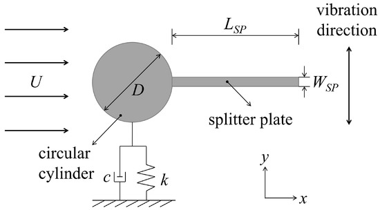
Figure 1.
Sketch of a splitter plate attached to an elastically mounted circular cylinder constrained to oscillate in the transverse (y-) direction.
2.1. Mathematical Modeling
The flow past the cylinder-plate assembly is usually laminar at a low Reynolds number ( where is the kinematic fluid viscosity), consequently, the flow dynamics is governed by the two-dimensional (2D) unsteady incompressible Navier-Stokes (NS) equations:
where the subscript i refers to the Cartesian component of a vector in the i-th direction with for a two-dimensional problem; and are the Cartesian components of the position vector in the streamwise and transverse directions, respectively; and are the components of the velocity vector in x- and y-directions, respectively; p, and are the pressure, fluid density, and fluid kinematic viscosity; and, t is time. In the numerical simulations conducted herein, ρ = 1.225 kg m−3 and ν = 0.01 m2 s−1.
The transverse vibration of cylinder-plate assembly, driven by the unsteady hydrodynamic fluid forces acting on it, can be modelled by a mass-spring-damper system, which assumes the following form:
where y, and represent the displacement (in m), velocity (in m s−1) and acceleration (in m s−2) of the moving body in the cross-flow direction, respectively; m is the total oscillating mass per unit length (in kg m−1); c and k are structural damping coefficient per unit length (in N s m−2) and spring stiffness per unit length (in N m−2), respectively; denotes the fluctuating transverse force per unit length acting on the vibrating system (in N m−1). Other non-dimensional quantities used in this study include: the dimensionless transverse displacement ; the reduced velocity defined in terms of the structural natural frequency in a quiescent fluid; the damping ratio ; and, the mass ratio defined as the ratio of the total structural mass to the fluid mass displaced by the moving body. The instantaneous lift and drag coefficients are defined as and , respectively. Here, and are force components in the cross-flow and in-line directions, respectively. The dimensionless time τ is defined as —since D = 1 m and U = 1 m s−1, the dimensional time t has the same numerical value as τ so, for simplicity, we will henceforth use t to refer to both the dimensional and dimensionless time. Finally, in the numerical simulations conducted herein, the structural damping coefficient per unit length c = 0 N s m−2 (viz., there was no structural damping in the system dynamics).
2.2. Numerical Modelling
The two-dimensional numerical simulations in this study are performed using OpenFOAM, an open-source computational fluid dynamics (CFD) software system library implemented in C++.
2.2.1. Simulation Set-Up
As shown in Figure 2, the elastically mounted cylinder-plate assembly is located at the origin of a rectangular Cartesian computational domain, the dimensions of which are (where and are the distance from cylinder center to inlet and outlet planes, respectively) in the x-direction and W in the y-direction. The center of the cylinder (in the equilibrium position) is equidistant () from the top and bottom boundaries of the domain. Considering that large-amplitude transverse oscillations may occur, the size of computational domain is chosen carefully to ensure that the four (artificial) boundaries of the domain do not have an effect on the motion of structure. The choice of an optimal computational domain size to satisfy this condition is described in Section 3.1.
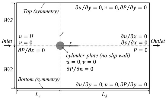
Figure 2.
Sketch definition of computational domain and boundary conditions used in the numerical simulations.
Figure 2 also summarizes the boundary conditions in our numerical simulations. A Dirichlet boundary condition is applied for the two velocity components (u and v) at the inlet plane and along the cylinder-plate assembly surface as well as for fluid pressure (P) at the outlet plane. A Neumann boundary condition [32,33,37] is imposed for the fluid pressure at the inlet plane and along the cylinder-plate assembly surface and for velocity components at the outlet plane. The specified boundary conditions and the corresponding mathematical expressions of these boundary conditions are summarized in Table 1. The initial velocity and pressure fields in the computational domain are set to zero.

Table 1.
Boundary conditions and their corresponding mathematical expressions.
In this study, the proprietary software package Ansys ICEM CFD is used to generate a two-dimensional structured hexahedral grid to cover the entire computational domain—this structured grid design is used to reduce the computational time and to obtain more accurate results. As depicted in Figure 3, the grid cells surrounding the cylinder and the splitter plate are refined and the entire mesh covering the computational domain is of high quality—more specifically, the quality of the mesh used in our numerical simulations is between 0.95 to 1 as confirmed using the mesh check tool in the Ansys ICEM CFD package.
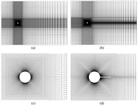
Figure 3.
Computational mesh used to discretize the computational domain. Mesh partitioning of whole domain and local mesh refinement close to the surface of the bare circular cylinder (a,c) and the cylinder-plate assembly (b,d).
2.2.2. Numerical Discretization
The numerical schemes used to discretize the various terms in the NS equations are as follows: (1) temporal derivative term is discretized using a second-order accurate implicit backward scheme; (2) spatial discretization of the convective term uses a second-order accurate Gaussian linear upwind scheme; and, (3) the diffusion term is discretized using a second-order accurate Gauss linear corrected scheme. After the discretization of the NS equations, an iterative method is used to solve the linear algebraic equation system. To this purpose, the smoothSolver with symGaussSeidel smoother and the geometric-algebraic multi-grid (CAMG) with GaussSeidel smoother in OpenFOAM are used to solve the discretized systems of equations for velocity and pressure, respectively. The fluid dynamics is addressed using the transient pimpleFOAM solver which the PIMPLE algorithm—a hybrid between the steady SIMPLE (Semi-Implicit Method for Pressure-Linked Equations) and transient PISO (Pressure Implicit with Splitting Operators)—is used to deal with the pressure-velocity coupling of the continuity and momentum equations. The pimpleFOAM solver allows a larger time step size to be used in the numerical simulations. In order to ensure a stable and convergent calculation at every time step, the time step is adjusted to control the maximum Courant-Friedrichs-Lewy (CFL) number which, for our numerical simulations, is specified to have a value of 0.8 at each time step.
With respect to the structural motion, the implicit Newmark- scheme (, ) is utilized to numerically solve the mass-spring-damper equation of motion (Equation (3)) to give the displacement, velocity and acceleration of the cylinder-plate assembly at each time step.
2.2.3. Grid Update
Owing to the oscillatory motion of the cylinder-plate assembly, a dynamic meshing methodology which can accommodate a changing geometry due to this motion is utilized in our numerical simulations. To this purpose, the whole computational domain is divided into three distinct regions through the definition of two parameters—innerDistance and outerDistance—which (1) allows the moving mesh zone between the body surface and innerDistance to move with the cylinder-plate assembly without any deformation; (2) defines a mesh morphing zone between innerDistance and outerDistance, allowing the mesh in this zone to be deformed and updated at each time step using a spherical linear interpolation scheme (SLERP); and, (3) specifies the static mesh zone beyond outerDistance. The partitioning of computational domain into three regions through the specification of innerDistance and outerDistance is displayed in Figure 4. The existence of a directly moving mesh zone can effectively improve the simulation accuracy in the mesh region surrounding the cylinder-plate assembly, and guarantee the computational stability of the numerical solution, particularly when the structure undergoes a significant displacement [1].
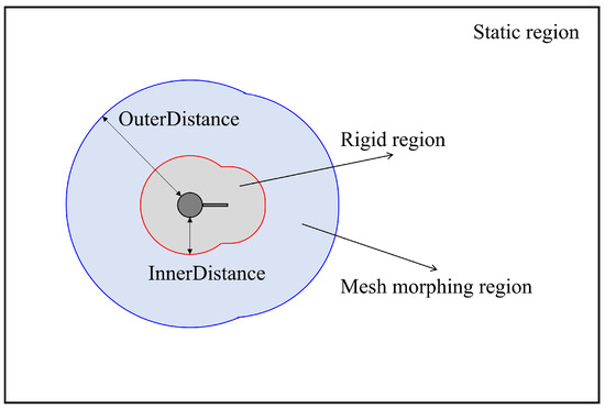
Figure 4.
Partitioning of the computational domain into three regions by the specification of two parameters (innerDistance and outerDistance) in the dynamic meshing methodology.
In order to achieve a two-way FSI during the simulation, the original NS equations are reformulated in the framework of the arbitrary Lagrangian Eulerian (ALE) methodology—this involves the inclusion of the relative velocity between the fluid and mesh in the convective term of momentum transport equation (Equation (2)) to give
Here, is j-th component of the grid velocity vector characterizing the moving mesh.
An explicit FSI algorithm is applied in our numerical simulations, for which the governing equations for the fluid and structure are solved successively at each time step. More precisely, the numerical solution of the FSI problem uses the following three-step procedure: namely, (1) solve the ALE-based NS equations (Equations (1) and (4)) to obtain the flow field information, so that the fluid force acting on the structure can be calculated by integrating the pressure and viscous friction on its surface; (2) substitute the computed fluid force into the right-hand side of Equation (3) as the forcing term and numerically solve the resulting equation to obtain the displacement, velocity and acceleration of the vibrating structure; and, (3) update the mesh (both the directly moving and morphing regions) based on the state of motion determined in step (2).
3. Numerical Model
The numerical simulations are influenced by a number of factors such as the computational domain size, the grid resolution and the dimensionless time step. A careful study has been undertaken to determine the most appropriate configuration of these critical factors in order to conduct the large number of simulations required with the least computational cost, while achieving an acceptable level of accuracy. The typical benchmark case of a one-degree-of-freedom VIV of a circular cylinder is used in sensitivity tests—in these tests, the Reynolds number, the mass ratio and the structural damping ratio are fixed at , and . The tests were conducted for a range of reduced velocities from 4–9, inclusive. The quantities of interest used to assess the computational accuracy include the maximum amplitude , root-mean-square (RMS) of the lift coefficient and mean of the drag coefficient . After the sensitivity studies, the present numerical model is validated.
3.1. Sensitivity Study of Domain
The sensitivity of the numerical solution to the size of the computational domain is investigated by varying the distance from the cylinder center to the outlet plane (, 45, and 65) and the width of the domain (, 40, 50, and 60) for a fixed distance from the cylinder center to the inlet plane ()— is fixed owing to the fact that the flow information “propagates” in the downstream direction so the impact of this dimension is negligible on the numerical solution. To investigate the influence of the computational domain size, we fixed the grid-stretching ratio around the cylinder to a value of 1.06, the number of mesh elements (cells) around the circumference of the cylinder to a value of and the total number of cell elements used to discretize the computational domain to a value of about 20,000. Moreover, the time step used in domain tests is fixed at s.
Table 2 summarizes the results of a sensitivity study on the computational domain size. All the numerical simulations were conducted for a reduced velocity of . Domains 1–3 embody the effect of the downstream domain dimension on the numerical solution and show the relative differences in the three quantities of interest as increases from 25 to 45 to 65 with the width fixed at a value of 40. It can be seen that the percent relative differences in the predicted values of the three quantities between domains 1 and 2 are significant. Moreover, the percent relative differences in the predicted values of , and are only 0.15%, 0.62% and 0.05%, respectively, between domains 2 and 3. In view of these results, (or, equivalently, where ) is chosen as the downstream dimension for the computational domain. Domains 4, 2, 5, and 6 embody the influence of the domain width W on the numerical solution for a fixed value of the domain length . It is seen that shows the largest percent relative difference of 22.24% between and 40, while and exhibit smaller percent relative differences of 8.26% and 4.33%, respectively. Moreover, the relative percent differences in the quantities of interest are small for compared to those for —a percent relative difference of 1.25% is observed for and generally negligible percent relative differences for and . Similarly, the percent relative differences are very small for when compared to those for . As a consequence, an appropriate domain width for the numerical simulations is . In summary, a computational domain with a length of (viz., and ) and a width provides the best balance between computational effort and accuracy for the numerical simulations. The corresponding blockage (ratio of the cylinder diameter D to the domain width W) is 0.025.

Table 2.
Dependence of numerical results on the size of the computational domain. All the numerical simulations were conducted at fixed values of , , , , and .
3.2. Sensitivity Study of Grid
A grid sensitivity study has been conducted to ensure the numerical results are independent of the grid resolution. To simulate the VIV of a circular cylinder, a non-uniform stretched mesh composed of quadrilateral elements is used to tessellate in the entire computational domain (see Figure 3a,c). The mesh is characterized by the number of nodal points () along the circumference of the cylinder, the height of first grid layer away from the cylinder surface (), and the number of nodes along the radial direction within the dense mesh area surrounding cylinder (). More specifically, grid cells are distributed along the length of the splitter plate and three grid cells are distributed evenly along the width of the plate. Four different meshes ranging from coarse to dense are used in the sensitivity study—for each mesh, is fixed at in order to satisfy the criterion of (where is the normal wall coordinate, y is the distance from the wall, and is the friction velocity). The grid resolution is varied by changing the values of in the range from 80 to 200 and of in the range from 48 to 76—these variations change the total number of cell elements () in the mesh. In these numerical simulations, a computational domain size of and a time step of s are used.
Four different meshes (grids) and their influence on the numerical solution are exhibited in Table 3. It can be seen that the percent relative differences in the predicted quantities between grid 1 (coarse) and grid 2 (intermediate) are significant as are those between grid 2 (intermediate) and grid 3 (fine). Moreover, the percent relative differences in the three quantities between grid 3 (fine) and grid 4 (very fine) is small, with the largest percent relative difference of 0.86% occurring for . In order to balance computational effort with accuracy, we will use grid 3 for the numerical simulations conducted in this paper.

Table 3.
Dependence of numerical results on the grid resolution. All the numerical simulations were conducted at fixed values of , , , and .
3.3. Sensitivity Study of Time Step
The sensitivity of numerical results on the dimensionless time step size has been investigated. These sensitivity tests were conducted on a fixed computational domain size (domain 2) and grid resolution (grid 3) with the numerical solutions obtained using three different time step sizes: namely, s, 0.01 s, and 0.005 s. The results are summarized in Table 4. A perusal of this table shows that significant percent relative differences in the three quantities are observed between the results obtained for s and those for s. More specifically, the percent relative difference for the predicted value of using s compared to that using s is 19.393%. In contrast, the percent relative differences between results obtained for s and 0.005 s is much smaller—again, the largest percent relative difference occurs for , but this difference is only 5.45%. From these considerations, a time step of s is used in our numerical simulations as this choice represents the best compromise between computational efficiency and solution accuracy.

Table 4.
Dependence of numerical results on the time step size. All the numerical simulations were conducted at fixed values of , , , and .
3.4. Model Validation
To validate the predictive accuracy of the numerical model used in this study, we will simulate the transverse VIV of a circular cylinder and the transverse FIV of the cylinder-plate assembly, and compare our predictions with some previous numerical results. Three different simulation cases are used for this purpose, involving different Reynolds numbers, and structural mass and damping ratios.
The numerical properties of the first simulation case is the same as that in sensitivity studies: namely, , , and for a range of reduced velocity Ur = 2–9.5. The predictions of the dependence of three (dimensionless) quantities of interest , and on the reduced velocity is exhibited in Figure 5. These results are compared with the predictions obtained from some previous numerical investigations [39,40,41,42,43]. A careful examination of the figure shows that the normalized maximum transverse displacement and the lift and drag force coefficients are in excellent conformance with previous numerical simulations. This implies that the numerical model used in this study can accurately predict the VIV response of a circular cylinder in terms of the onset of VIV, the lock-in range and the maximum amplitude of oscillation.
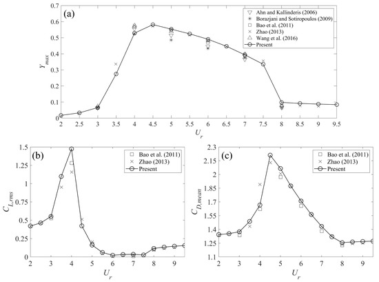
Figure 5.
Comparison of numerical results between the present study and previous numerical investigations (Ahn and Kallinderis [39], Borazjani and Sotiropoulos [40], Bao et al. [41], Zhao [42], and Wang et al. [43]): (a) normalized maximum transverse displacement as a function of ; (b) root-mean-square lift coefficient as a function of ; and, (c) mean drag coefficient as a function of . The current numerical simulations are of the VIV response of a circular cylinder for , , and . The resolution of used in the present simulations is 0.5.
The second case involves the numerical simulation of the VIV response of a circular cylinder for , , and for . The numerical parameters in this example correspond exactly to those used for the numerical simulations of the cylinder-plate assembly conducted herein. Figure 6 compares our predictions of the normalized maximum transverse displacement as a function of with results obtained from some previous numerical studies [44,45]. A good agreement is obtained between the present simulations and these previous numerical results—albeit, our predictions of are slightly larger than those obtained from previous numerical studies in the range of reduced velocities from about 4.5 to 8. The reason for this small difference is that the mass ratio used in these previous numerical studies was —this value of the mass ratio is larger than that used in the current simulations where .
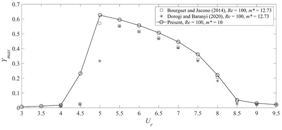
Figure 6.
Comparison of numerical results between the present study and previous numerical investigations (Bourguet and Jacono [44], Dorogi and Baranyi [45]) for the normalized maximum transverse displacement as a function of the reduced velocity . The current numerical simulations are of the VIV response of a circular cylinder for , , and . The resolution of used in present simulations is 0.5.
Figure 7 compares the maximum transverse displacement of elastically mounted cylinder-plate assemblies with plate lengths of , 0.5, 0.75 and 1 with the corresponding numerical results of Sun et al. [32] and Zhang et al. [38]. All the numerical simulations shown here were conducted at , and . A careful perusal of Figure 7 shows that the present simulations are in excellent conformance with previous numerical results for both short plate lengths associated with self-limiting oscillations at small values of the reduced velocity (see Figure 7a,b) and for the longer plates associated with non-limiting oscillations at the larger values of the reduced velocity (see Figure 7c,d).
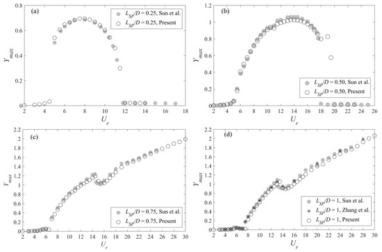
Figure 7.
Comparison of numerical results between the present study and previous numerical investigations (Sun et al. [32], Zhang et al. [38]) for the normalized maximum transverse displacement as a function of the reduced velocity . The current numerical simulations are of the FIV response of a cylinder-plate assembly with various plate lengths for , , and .
4. Results
In this section, the combined effect of splitter-plate length and reduced velocity on the FIV of cylinder-plate assembly is analyzed in terms of the vibration amplitude, the oscillation frequency and the fluid forces acting on the moving body.
4.1. Vibration Characteristics
Figure 8 and Figure 9 display the three-dimensional (3D) plots of the maximum transverse displacement (amplitude) and the non-dimensional dominant transverse displacement oscillation frequency , respectively, as a function of the splitter-plate length and the reduced velocity . A careful examination of these plots reveals the dynamical characteristics of the nonlinear system that can be divided into three regimes: namely, (1) in the regime where –0.5, the cylinder-plate assembly undergoes a self-limiting vibration that occurs over a limited range of the reduced velocity with the oscillation frequency locked near the structural natural frequency (which can be identified as a VIV-type response); (2) in the regime where –3.5, the cylinder-plate assembly undergoes a non-limited vibration with a monotonically increasing oscillation amplitude with increasing reduced velocity—this regime exhibits complex frequency characteristics and can be identified as a galloping-type response; and, (3) in the regime where , there is no obvious oscillation induced on cylinder-plate assembly, at least for values of up to 30. Figure 8 and Figure 9 show clearly that the dynamical response of a cylinder-plate assembly has a strong dependence on the splitter-plate length and the reduced velocity.
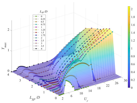
Figure 8.
The normalized vibration amplitude plotted as a function of the plate length and the reduced velocity .
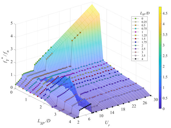
Figure 9.
The dominant vibration frequency normalized by structural natural frequency () plotted as a function of the plate length and the reduced velocity .
Although the three-dimensional plots exhibit qualitatively the relationship between the plate length, reduced velocity, and maximum transverse displacement, a detailed and more quantitative elucidation of the various controlling factors that influence the oscillatory response of a cylinder-plate assembly requires two-dimensional plots. Consequently, in order to obtain more details on the nature of the amplitude and frequency response for a cylinder-plate assembly, Figure 10 exhibits two-dimensional plots of and as a function of stratified by the value of the plate length . The bare circular cylinder (without the splitter plate, so ) undergoes VIV with a lock-in range of –8.5 and a maximum vibration amplitude of about at . The non-dimensional dominant frequency of displacement oscillations increases with increasing before the onset of VIV, attaining a value of unity when lock-in is achieved (implying that is exactly locked to the structural natural frequency ). The non-dimensional dominant frequency increases linearly again when the system transitions out of lock-in. The dynamic response of the bare circular cylinder is significantly different than that of a splitter plate attached to the cylinder.
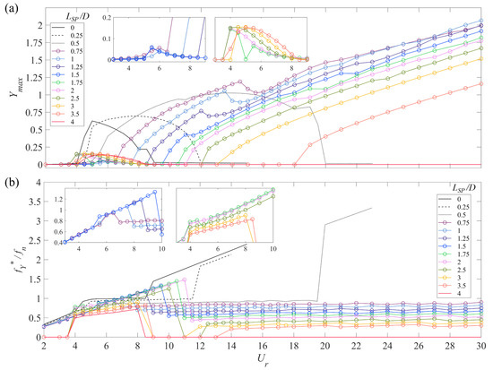
Figure 10.
Plots of (a) the normalized vibration amplitude () and (b) the normalized dominant vibration frequency () as a function of the reduced velocity stratified in terms of the splitter-plate length .
With the inclusion of a relatively short splitter-plate of length , the pure VIV response is enhanced in the sense that it has a wider lock-in range (namely, –12). The magnitude of the transverse displacement has a maximum value of about over an extended range of values of the reduced velocity, in contrast to the case of a bare cylinder where decreases rapidly in magnitude with increasing after achieving a peak value at lock-in. Furthermore, with the inclusion of the short splitter-plate, is approximately equal to over the wider range of reduced velocities where lock-in occurs.
A cylinder-plate assembly with undergoes a further reinforced vibration over a much wider lock-in range of –20 (almost four times the VIV lock-in range of a bare cylinder) with a larger amplitude of vibration. The frequency response exhibits a similar pattern, but the dominant oscillation frequency is locked on to a value that is smaller than the natural frequency (more specifically, to ). Consequently, a reasonable guess is that the cylinder-plate assembly with undergoes an integrated VIV-galloping response.
For an even longer plate length of , the cylinder-plate assembly first undergoes a weak oscillation with an amplitude at where also exhibits a small increase. The system manifests an onset of galloping at with a nearly linear increase in amplitude with increasing —attaining an amplitude of at . The associated dominant frequency maintains a constant value of 0.84 over the range of where galloping occurs. Cylinder-plate assemblies with , 1.25 and 1.5 exhibit very similar dynamical response characteristics as that with . However, the onset of galloping occurs at larger values of and the dominant frequency over the range of where galloping occurs is smaller for the longer plate lengths. For example, the onset of galloping for , 1.25, and 1.5 occurs at , 9, and 10, respectively. Furthermore, , 0.7, and 0.65 in the range of associated with galloping for plate lengths of , 1.25, and 1.5, respectively. Therefore, with increasing the amplitude decreases (albeit slowly)—the only exception to this rule occurs at the larger values of (e.g., the amplitude for crosses that for at about –27). Another interesting phenomenon is that the amplitude plots of , 1 and 1.25 exhibits a “kink” in the amplitude response (where the amplitude decreases abruptly) at , 14 and 12.5, respectively. However, for , the expected “kink” morphs instead into an interval where the amplitude is constant at –11.5.
When the plate length is increased to , the small vibrations occurring at small become stronger with increasingly reduced velocity, attaining a maximum amplitude of at . The onset of galloping in this case does not occur until and the dominant vibration frequency in the galloping regime is reduced (to ) as is the transverse displacement compared to that of the shorter plate lengths. The cylinder-plate assemblies for , 2.5, 3 and 3.5 exhibit similar dynamical response characteristics to those for —however, the onset of galloping occurs at progressively larger values of the reduced velocity (e.g., at , 12, 13 and 18, respectively) and the dominant oscillation frequency in the galloping regime is progressively smaller (e.g., , 0.43, 0.35 and 0.3, respectively). In addition, the frequency response exhibits some noteworthy attributes: namely, (1) for –3.5, the dominant oscillation frequency in the lower range of gradually increases to the structural natural frequency (but does not exceed this value), in contrast to the behavior for shorter plate lengths (e.g., for –2.5) where the dominant oscillation frequency can exceed (and, indeed can attain values up to about ); and, (2) for –3.5, there exist ranges of the reduced velocity where vibration ceases (e.g., –12, 9–11 and 9–13).
For the longest plate length considered in this study, a small oscillation occurs in the range –8. Moreover, no galloping is triggered, at least over the range of reduced velocity investigated in this study—although, it cannot be ruled out that galloping might not occur at still larger values of .
4.2. Fluid Force Characteristics
Figure 11 and Figure 12 exhibit three-dimensional plots of and of , respectively, as a function of the plate length and the reduced velocity for a cylinder-plate assembly. A perusal of this figure suggests that the lift force is strongly correlated with the onset of VIV and galloping—the lift force is seen to increase significantly in the range of reduced velocities associated with VIV or galloping. In contrast, the mean drag force embodied in exhibits appreciable variations only when the self-limiting VIV response occurs (e.g., for –0.25).
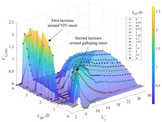
Figure 11.
Three-dimensional plot of the root-mean-square lift coefficient as a function of the splitter-plate length and the reduced velocity .
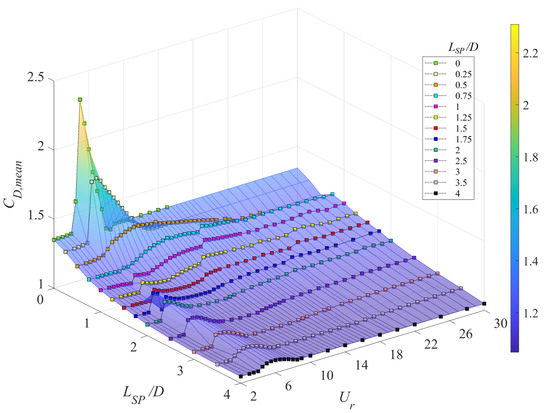
Figure 12.
Three-dimensional plot of the time-averaged (mean) drag coefficient as a function of the splitter-plate length and the reduced velocity .
Figure 13a,b display the fluid force coefficients and of the cylinder-plate assembly, respectively, as a function of the reduced velocity stratified by the different values of the plate length . For the bare circular cylinder, the lift and drag coefficients first increase sharply at the onset of VIV, reaching peak values of and at . After VIV onset, decreases rapidly to near zero during lock-in and thereafter increases slightly again to a value of 0.2 and remains constant at this value when the system has transitioned out of lock-in. Furthermore, also undergoes a sudden decrease from a peak value of 2.35 to a value of 1.35 where it remains constant with increasing —the latter value for is the same as that before lock-in.
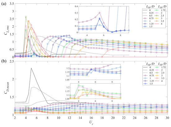
Figure 13.
Variation of aerodynamic fluid forces acting on a cylinder-plate assembly: (a) the root-mean-square lift coefficient and (b) the time-averaged (mean) drag coefficient as a function of the reduced velocity and stratified with respect to the plate length .
For –0.5, the variation of with adheres basically to a similar trend as that for a bare circular cylinder—the main difference is that the lift coefficient for the cylinder with the splitter plate exhibits a slightly larger peak value of 1.44 and gradually decreases to a value 0.2 in the lock-in range instead of a near-zero value for the bare circular cylinder. By contrast, the value of the drag coefficient is reduced compared to that for the bare circular cylinder—more specifically, the peak value of for and this peak value is even smaller for . In this case, the maximum of is broad, occurring over a wide range of values for .
If cylinder-plate assembly undergoes a galloping-type response, the lift coefficient exhibits a completely different behavior. For –1.5, first increases to a small peak value (first peak) at (which is associated with a very small oscillation) and then decreases towards zero until the onset of galloping, at which point increases again to attain a large peak value (second peak) of about 1.2–1.4. This is followed by a gradual decrease in the value of within the galloping regime. On the other hand, only exhibits a very small increase in value at the onset of oscillatory motion and remains at a constant value within the galloping regime. There are also variations in the values of and at the location of “kinks” in the amplitude response.
For –3.5, the first peak of the lift coefficient attains a much higher value of between 1.75–2.7. This is comparable to the fluid force responsible for the VIV of a bare circular cylinder. However, the corresponding vibration at small values of has a maximum amplitude of , which is only one-third of the value associated with the VIV response (cf. Figure 13). Moreover, attaching a longer plate to the cylinder results in a smaller second increase in the lift coefficient before the onset of galloping followed by a slow decrease of within the galloping regime. In contrast, the variation as a function of is much simpler—there is a rapid increase at the onset of the small oscillatory motion and a gradual increase at the onset of galloping. Moreover, the drag coefficient is constant within the galloping regime. Finally, this constant value of in the galloping regime is smaller for longer plate lengths.
A cylinder-plate assembly with only exhibits very small vibrations at small values of . In this case, it is seen that both and first increase at –8 and then decrease again to zero at the larger values of the reduced velocity.
4.3. Components of Transverse Force
For a cylinder-plate assembly moving together as a rigid body, the aerodynamic force will act on both the circular cylinder and the splitter-plate—the latter cannot be ignored, especially for a long plate. To determine the contribution of various force components to the system oscillations, Figure 14 displays the oscillation amplitude superimposed on the fluid forces exerted on the cylinder and the plate. It should be noted that the drag force is included only for the self-limiting VIV-type oscillations (which are present when –0.5)—the drag force has a negligible effect in the galloping regime.
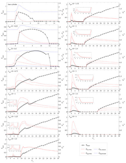
Figure 14.
The maximum vibration amplitude , the root-mean-square lift force coefficient and the mean drag force coefficient acting on the cylinder (, ) and the plate (, ) as a function of the reduced velocity for six representative values of the splitter-plate length.
For the cylinder-plate assembly undergoing a self-limiting oscillation (–0.5), the transverse force acting on the cylinder is much larger than that acting on the splitter-plate, although the former decreases while the latter increases with an increasing . As a consequence, the additional plate-force might play a leading role in inducing stronger oscillations in the system over a wider range of and in producing a larger vibration amplitude over this range.
For –1.5, the cylinder-plate assembly undergoes a galloping-dominated response. The lift force on the cylinder in the galloping regime is larger than that on the splitter plate in general. The difference in the lift force between the cylinder and the plate decreases with increasing plate length until at which point the lift force on the cylinder and plate are nearly equal in value. Before the onset of galloping, the lift force on the cylinder is twice as large as that on the plate for small oscillations, but after that the former decreases towards zero, eventually becoming smaller than the latter (e.g., this occurs at –7.5, 7–8.5, and 7–9.5 for , 1.25, and 1.5, respectively).
For , the situation is reversed: namely, the lift force on the plate is generally larger than that on the cylinder for small oscillations and for galloping—this response may be associated with some special flow patterns. The difference between these two forces increases with increasing . As discussed above, the magnitude of transverse (lift) force with small oscillations is greatly increased relative to that for shorter plate lengths. In the quasi-stationary regime before the onset of galloping, the variation of the transverse force with exhibits some interesting behavior. More specifically, for , the lift force on the cylinder gradually decreases to zero, while the lift force on the plate remains small (but, non-zero)—this occurs at –10.5 and 7.5–11 for plate lengths of and 2, respectively. In contrast, the lift force on the cylinder and plate both are zero over this range of reduced velocities for longer plate lengths with –4.
It appears that the lift force on the cylinder () has a greater effect on the resulting dynamic response of the vibrating system, even though the value of this lift force is less than that on the plate (). This is supported by the fact that increases sharply at small values of the reduced velocity for . However, this sharp increase does not appear to induce a stronger secondary vibration—indeed, the lift force on the cylinder and the oscillation amplitude remain unchanged. The effect of appears to be closely related to the wake flow dynamics behind a vibrating cylinder-plate assembly in the form of the interaction between the splitter plate and the near-wake flow. Finally, when is larger than for the longer plates, the amplitude response appears to increase linearly with with less tendency for the existence of a “kink” (discontinuity in the slope) in this response.
5. Conclusions
The combined effects of the splitter-plate length and the reduced velocity on the transverse flow-induced vibration of an elastically mounted cylinder-plate assembly at a Reynolds number of 100 is investigated using numerical simulations in the present work.
For , a self-limiting oscillation is induced on the cylinder-plate assembly—this consists of either a VIV-only response (for ) or an integrated VIV-galloping response (for ). In comparison to the flow-induced vibrations of a bare circular cylinder, the former case has a significantly extended lock-in range, whereas the latter case has a larger reduced velocity range of structural motion with a smaller oscillation frequency. For cylinder-plate assemblies with , an unlimited galloping response is triggered consisting of a steadily increasing oscillation amplitude that is preceded by a VIV regime before the onset of galloping. The two regimes here become increasingly separated from one another as the plate length increases (viz., from a significant to no overlap between the two regimes associated with VIV and galloping). The lift force acting on the circular cylinder has an important contribution on the dynamic response of the vibrating body. In contrast, the component of the force acting on the splitter-plate has a more important effect on the dynamics of the flow surrounding the cylinder-plate assembly.
Further investigations on the branching behavior and wake structure would be of great interest to gain a deeper understanding of the physical mechanisms underpinning the FIV response of a cylinder-plate assembly reported herein.
Author Contributions
Conceptualization, Y.W., F.-S.L., E.Y. and G.C.; methodology, Y.W., F.-S.L. and E.Y.; software, Y.W.; validation, Y.W.; formal analysis, Y.W.; data curation, Y.W.; writing—original draft preparation, Y.W.; writing—review and editing, E.Y. and F.-S.L.; supervision, F.-S.L.; project administration, F.-S.L. and E.Y.; funding acquisition, F.-S.L. and E.Y. All authors have read and agreed to the published version of the manuscript.
Funding
This research was funded by the Natural Sciences and Engineering Research Council of Canada (NSERC) Discovery Grants Program Grant Number 50503-10234. It was made possible by the facilities of the Shared Hierarchical Academic Research Computing Network (SHARCNET: www.sharcnet.ca) and Compute/Calcul Canada.
Data Availability Statement
The data that support the findings of this study are available from the corresponding author upon reasonable request.
Conflicts of Interest
The authors declare no conflict of interest.
References
- Wu, Y.; Cheng, Z.; McConkey, R.; Lien, F.S.; Yee, E. Modelling of flow-induced vibration of bluff bodies: A comprehensive survey and future prospects. Energies 2022, 15, 8719. [Google Scholar] [CrossRef]
- Arumuga, P.D.; Kumar, G.V.; Dass, A.K. Lattice Boltzmann simulation of flow over a circular cylinder at moderate Reynolds numbers. Therm. Sci. 2014, 18, 1235–1246. [Google Scholar] [CrossRef]
- Billah, K.Y.; Scanlan, R.H. Resonance, Tacoma Narrows bridge failure, and undergraduate physics textbooks. Am. J. Phys. 1991, 59, 118–124. [Google Scholar] [CrossRef]
- Hu, G.; Tse, K.T.; Kwok, K.C. Enhanced performance of wind energy harvester by aerodynamic treatment of a square prism. Appl. Phys. Lett. 2016, 108, 123901. [Google Scholar] [CrossRef]
- Song, J.; Hu, G.; Tse, K.; Li, S.; Kwok, K. Performance of a circular cylinder piezoelectric wind energy harvester fitted with a splitter plate. Appl. Phys. Lett. 2017, 111, 223903. [Google Scholar] [CrossRef]
- Hu, G.; Tse, K.T.; Wei, M.; Naseer, R.; Abdelkefi, A.; Kwok, K.C. Experimental investigation on the efficiency of circular cylinder-based wind energy harvester with different rod-shaped attachments. Appl. Energy 2018, 226, 682–689. [Google Scholar] [CrossRef]
- Foo, K.; Liang, Y.; Weihs, G.F. CFD study of the effect of SWM feed spacer geometry on mass transfer enhancement driven by forced transient slip velocity. J. Membr. Sci. 2020, 597, 117643. [Google Scholar] [CrossRef]
- Foo, K.; Liang, Y.; Tan, C.K.; Weihs, G.F. Coupled effects of circular and elliptical feed spacers under forced-slip on viscous dissipation and mass transfer enhancement based on CFD. J. Membr. Sci. 2021, 637, 119599. [Google Scholar] [CrossRef]
- Apelt, C.; West, G.; Szewczyk, A.A. The effects of wake splitter plates on the flow past a circular cylinder in the range 104 < R < 5×10⁴. J. Fluid Mech. 1973, 61, 187–198. [Google Scholar]
- Anderson, E.; Szewczyk, A. Effects of a splitter plate on the near wake of a circular cylinder in 2 and 3-dimensional flow configurations. Exp. Fluids 1997, 23, 161–174. [Google Scholar] [CrossRef]
- Kwon, K.; Choi, H. Control of laminar vortex shedding behind a circular cylinder using splitter plates. Phys. Fluids 1996, 8, 479–486. [Google Scholar] [CrossRef]
- Hwang, J.Y.; Yang, K.S.; Sun, S.H. Reduction of flow-induced forces on a circular cylinder using a detached splitter plate. Phys. Fluids 2003, 15, 2433–2436. [Google Scholar] [CrossRef]
- Akilli, H.; Sahin, B.; Tumen, N.F. Suppression of vortex shedding of circular cylinder in shallow water by a splitter plate. Flow Meas. Instrum. 2005, 16, 211–219. [Google Scholar] [CrossRef]
- Mittal, S. Effect of a “slip” splitter plate on vortex shedding from a cylinder. Phys. Fluids 2003, 15, 817–820. [Google Scholar] [CrossRef]
- Ozono, S. Flow control of vortex shedding by a short splitter plate asymmetrically arranged downstream of a cylinder. Phys. Fluids 1999, 11, 2928–2934. [Google Scholar] [CrossRef]
- Dehkordi, B.G.; Jafari, H.H. On the suppression of vortex shedding from circular cylinders using detached short splitter-plates. J. Fluids Eng. 2010, 132, 044501. [Google Scholar] [CrossRef]
- Assi, G.R.; Bearman, P.; Kitney, N. Low drag solutions for suppressing vortex-induced vibration of circular cylinders. J. Fluids Struct. 2009, 25, 666–675. [Google Scholar] [CrossRef]
- Hwang, J.Y.; Yang, K.S. Drag reduction on a circular cylinder using dual detached splitter plates. J. Wind Eng. Ind. Aerodyn. 2007, 95, 551–564. [Google Scholar] [CrossRef]
- Cimbala, J.M.; Garg, S. Flow in the wake of a freely rotatable cylinder with splitter plate. AIAA J. 1991, 29, 1001–1003. [Google Scholar] [CrossRef]
- Gu, F.; Wang, J.; Qiao, X.; Huang, Z. Pressure distribution, fluctuating forces and vortex shedding behavior of circular cylinder with rotatable splitter plates. J. Fluids Struct. 2012, 28, 263–278. [Google Scholar] [CrossRef]
- Xu, J.C.; Sen, M.; Gad-el Hak, M. Low-Reynolds number flow over a rotatable cylinder-splitter plate body. Phys. Fluids A Fluid Dyn. 1990, 2, 1925–1927. [Google Scholar] [CrossRef]
- Lu, L.; Guo, X.l.; Tang, G.q.; Liu, M.m.; Chen, C.q.; Xie, Z.h. Numerical investigation of flow-induced rotary oscillation of circular cylinder with rigid splitter plate. Phys. Fluids 2016, 28, 093604. [Google Scholar] [CrossRef]
- Zhang, M.; Wang, X.; Øiseth, O. Torsional vibration of a circular cylinder with an attached splitter plate in laminar flow. Ocean Eng. 2021, 236, 109514. [Google Scholar] [CrossRef]
- Zhu, H.; Tang, T.; Alam, M.; Song, J.; Zhou, T. Flow-induced rotation of a circular cylinder with a detached splitter plate and its bifurcation behavior. Appl. Ocean Res. 2022, 122, 103150. [Google Scholar] [CrossRef]
- Shukla, S.; Govardhan, R.; Arakeri, J. Dynamics of a flexible splitter plate in the wake of a circular cylinder. J. Fluids Struct. 2013, 41, 127–134. [Google Scholar] [CrossRef]
- Lee, J.; You, D. Study of vortex-shedding-induced vibration of a flexible splitter plate behind a cylinder. Phys. Fluids 2013, 25, 110811. [Google Scholar] [CrossRef]
- Wu, J.; Qiu, Y.; Shu, C.; Zhao, N. Flow control of a circular cylinder by using an attached flexible filament. Phys. Fluids 2014, 26, 103601. [Google Scholar] [CrossRef]
- Nakamura, Y.; Hirata, K.; Kashima, K. Galloping of a circular cylinder in the presence of a splitter plate. J. Fluids Struct. 1994, 8, 355–365. [Google Scholar] [CrossRef]
- Kawai, H. A discrete vortex analysis of flow around a vibrating cylinder with a splitter plate. J. Wind Eng. Ind. Aerodyn. 1990, 35, 259–273. [Google Scholar] [CrossRef]
- Nakamura, Y.; Hirata, K.; Urabe, T. Galloping of rectangular cylinders in the presence of a splitter plate. J. Fluids Struct. 1991, 5, 521–549. [Google Scholar] [CrossRef]
- Stappenbelt, B. Splitter-plate wake stabilisation and low aspect ratio cylinder flow-induced vibration mitigation. Int. J. Offshore Polar Eng. 2010, 20, ISOPE-10-20-3-190. [Google Scholar]
- Sun, X.; Suh, C.S.; Ye, Z.H.; Yu, B. Dynamics of a circular cylinder with an attached splitter plate in laminar flow: A transition from vortex-induced vibration to galloping. Phys. Fluids 2020, 32, 027104. [Google Scholar] [CrossRef]
- Sahu, T.R.; Furquan, M.; Jaiswal, Y.; Mittal, S. Flow-induced vibration of a circular cylinder with rigid splitter plate. J. Fluids Struct. 2019, 89, 244–256. [Google Scholar] [CrossRef]
- Liang, S.; Wang, J.; Hu, Z. VIV and galloping response of a circular cylinder with rigid detached splitter plates. Ocean Eng. 2018, 162, 176–186. [Google Scholar] [CrossRef]
- Zhu, H.; Li, G.; Wang, J. Flow-induced vibration of a circular cylinder with splitter plates placed upstream and downstream individually and simultaneously. Appl. Ocean Res. 2020, 97, 102084. [Google Scholar] [CrossRef]
- Assi, G.R.; Bearman, P.W. Transverse galloping of circular cylinders fitted with solid and slotted splitter plates. J. Fluids Struct. 2015, 54, 263–280. [Google Scholar] [CrossRef]
- Law, Y.Z.; Jaiman, R.K. Wake stabilization mechanism of low-drag suppression devices for vortex-induced vibration. J. Fluids Struct. 2017, 70, 428–449. [Google Scholar] [CrossRef]
- Zhang, M.; Øiseth, O.; Xu, F. Laminar flow-induced vibration of a three-degree-of-freedom circular cylinder with an attached splitter plate. Phys. Fluids 2021, 33, 113605. [Google Scholar] [CrossRef]
- Ahn, H.T.; Kallinderis, Y. Strongly coupled flow/structure interactions with a geometrically conservative ALE scheme on general hybrid meshes. J. Comput. Phys. 2006, 219, 671–696. [Google Scholar] [CrossRef]
- Borazjani, I.; Sotiropoulos, F. Vortex-induced vibrations of two cylinders in tandem arrangement in the proximity-wake interference region. J. Fluid Mech. 2009, 621, 321–364. [Google Scholar] [CrossRef]
- Bao, Y.; Zhou, D.; Tu, J. Flow interference between a stationary cylinder and an elastically mounted cylinder arranged in proximity. J. Fluids Struct. 2011, 27, 1425–1446. [Google Scholar] [CrossRef]
- Zhao, M. Flow induced vibration of two rigidly coupled circular cylinders in tandem and side-by-side arrangements at a low Reynolds number of 150. Phys. Fluids 2013, 25, 123601. [Google Scholar] [CrossRef]
- Wang, C.; Tang, H.; Duan, F.; Simon, C. Control of wakes and vortex-induced vibrations of a single circular cylinder using synthetic jets. J. Fluids Struct. 2016, 60, 160–179. [Google Scholar] [CrossRef]
- Bourguet, R.; Jacono, D.L. Flow-induced vibrations of a rotating cylinder. J. Fluid Mech. 2014, 740, 342–380. [Google Scholar] [CrossRef]
- Dorogi, D.; Baranyi, L. Identification of upper branch for vortex-induced vibration of a circular cylinder at Re = 300. J. Fluids Struct. 2020, 98, 103135. [Google Scholar] [CrossRef]
Disclaimer/Publisher’s Note: The statements, opinions and data contained in all publications are solely those of the individual author(s) and contributor(s) and not of MDPI and/or the editor(s). MDPI and/or the editor(s) disclaim responsibility for any injury to people or property resulting from any ideas, methods, instructions or products referred to in the content. |
© 2023 by the authors. Licensee MDPI, Basel, Switzerland. This article is an open access article distributed under the terms and conditions of the Creative Commons Attribution (CC BY) license (https://creativecommons.org/licenses/by/4.0/).