Abstract
The microstructure and suspended particle behavior should be considered when studying the flow properties exhibited by particle suspension. In addition, particle migration, also known as Segré–Silberberg effects, alters the microstructure of the suspension and significantly affects the viscosity properties of the suspension. Therefore, particle behavior with respect to the changes in mechanical factors should be considered to better understand suspension. In this study, we investigated the particle behavior in asymmetric velocity profiles with respect to the channel center numerically using the lattice Boltzmann method and a two-way coupling scheme. Our findings confirmed that the final equilibrium position of particles in asymmetric velocity profiles converged differently between the outer and inner wall sides with respect to the channel center. This indicates that the mechanical equilibrium position of particles can be changed by asymmetric velocity profiles. In addition, centrifugal force acting on the particles is also important in the study of equilibrium position. These results suggest that the microstructure and viscosity characteristics of a suspension in a pipe could be handled by changes in velocity profiles.
1. Introduction
Rheology is a discipline that deals with the study of deformation and flow in all materials in general. Hence, it is essential to understand the rheological properties of materials, as rheology is closely related to the final properties of materials. Suspension systems (solid particles (solute) dispersed in a liquid (solvent)) are an important aspect of rheology and have wide applications in industrial products, food, medicine, cosmetics, blood works, etc. [1]. Therefore, studying the rheological properties of suspensions is essential to improving the quality of industrial products and facilitating advanced technological innovations. The most demanding factors for suspension properties include concentration [2], shape [3,4], interaction [5], and the spatial arrangement of the particles dispersed in suspension [6].
Examining changes in microstructure, generally defined by the relative position of suspended particles, is important to understanding the rheological properties of suspensions [7,8]. Einstein’s viscosity formula [9] can be used to estimate the macroscopic viscosity of a suspension (Equation (1)).
where is the effective viscosity, is the viscosity of the solvent, is the intrinsic viscosity, and is the volume fraction of suspended particles. Intrinsic viscosity for two dimensions and for three dimensions [9,10]. This viscosity equation indicates that the volume fraction of particles in a suspension can be used to estimate the relative viscosity of the suspension. However, this formula has three assumptions: low concentration, negligibly small particles, and a steady and uniform flow. So, when the concentration, microstructure, and particle size of the particles in suspension deviate from these assumptions, it becomes difficult to apply Einstein’s viscosity formula.
The microstructure of a suspension depends on the inertial migration of suspended particles in a pipe flow. In inertial migration, the particles flowing in a pipe move in a direction perpendicular to the flow direction due to the effects of inertia and converge at a certain position. Segré and Silberberg [11,12] were the first to report this phenomenon, in which particles flowing down with inertia moved to a position about 0.6 times the tube radius. This change in the movement of particles owing to inertial effects is called Segré–Silberberg effects or tubular pinch effects. Many experimental [13,14,15], numerical [16,17,18], and theoretical [19] studies have examined this inertial migration. In particular, Matas et al. [13,14] studied inertial migration in the Poiseuille flow of particles. They suggested that the equilibrium position of the particles approaches the wall surface and the center of the channel with the increase in Reynolds numbers and confinement, respectively. Here confinement is defined as the ratio of particle diameter to channel width. Schonberg and Hinch [20] studied the inertial migration of a sufficiently small sphere in a Poiseuille flow. They suggested that the equilibrium position shifts toward the wall as the channel Reynolds number increases. Di Carlo et al. [21] examined the finite size effect in the inertial focusing in microfluids and evaluated the equilibrium position of particles using the lift force based on the particle’s lateral position. However, these changes in microstructure and particle-fluid interaction due to the changes in Reynolds number and confinement fail to evaluate suspension rheology using Einstein’s viscosity formula and assume the relative viscosity of the suspension in inertial pipe flow [22].
As the previous study of the relationship between macroscopic rheological property and dispersed particles suggested, Doyeux et al. [2] suggested that the total effective viscosity of suspensions can be expressed as a summation of each particle’s contribution. Okamura et al. [23] suggested that macroscopic viscosity can be estimated from particle size and spatial arrangements at limited low concentrations based on their study on the effects of circular particle interactions on macroscopic viscosity in a two-dimensional channel using a two-way coupling. These studies have greatly contributed to understanding the importance of the spatial arrangement of particles and particle-fluid interactions in the evaluation of the flow properties exhibited by suspensions. In addition, the viscosity characteristics of the suspension in pipe flow may be affected by the changes in the particle equilibrium position due to the Segré–Silberberg effect [24]. Therefore, the particle equilibrium position, which is strongly related to the microstructure, and the clarification of the relationship and mechanism with suspension properties play an important role in the evaluation of suspension properties or methods to handle suspension properties in the pipe flow.
The particle behavior-related macroscopic viscosity of suspension was changed by various factors such as particle shapes, solvent properties, dispersed conditions, environmental conditions, etc. Liu [25] and Kawaguchi et al. [26] investigated numerically the particle behavior of elliptical-shape particles. Additionally, Kawaguchi et al. [26] investigated the effects of particle behavior under various aspect ratios and suggested that the particle equilibrium position was changed by the aspect ratio of particles. Other studies focus on particle shapes. There are many studies focusing on not only particle shapes (e.g., capsule [27,28,29]) but also particle characteristics (e.g., red blood cells [30,31,32] and vesicles [33]). In studies focusing on solvent properties, Hu et al. [34] and Chrit et al. [35] suggested that the properties of non-Newtonian fluids as a solvent affect the particle equilibrium position. In studies focusing on dispersed conditions [36,37,38], Chun et al. [38] investigated the effects of bidispersity suspension on particle migration and suggested that the small particles were depleted from the midplane region by the accumulation of large particles there. In studies focusing on thermal fluids, Liu and Wu [39] assumed the thermal fluids as an environmental condition of the channel and suggested that the particle equilibrium position was changed by thermal convection. In studies focusing on body forces, Zhang et al. [40] assumed the centrifugal force and Coriolis force for environmental conditions and suggested that the particles shifted to the bottom wall because of these body forces. However, most studies on these spatial arrangements, particle behavior, and particle-fluid interactions have assumed neutral flow fields or symmetric flow fields with respect to the channel center. Only a few studies have focused on the macroscopic flow field changes that dominantly determine the spatial arrangement and behavior of particles. A previous study examined the balance between the repulsive forces from the channel wall and the wall-directed forces on finite-sized particles due to velocity gradients so as to study the particle equilibrium position in a Poiseuille flow [41]. Therefore, studying the changes in the macroscopic flow field can help in understanding the microstructure of the particles flowing in the channel and the rheology of the suspension. In addition, two-dimensional analysis not only can reduce the computational costs but also can evaluate the factors that determine particle behavior in detail because it can consider factors without complex effects (the effects of three-dimensional rotation motion of particles, etc.). From among the several methods to reproduce asymmetric velocity fields, one simple method is to eccentricate the flow field using a curved channel. In this study, we investigate the effects of changes in inertia and particle size on single-particle behavior in an asymmetric velocity field using numerical analysis of pressure-driven flow in a two-dimensional curvilinear channel.
2. Methods
In this study, the regularized lattice Boltzmann method [42,43] with an incompressible formulation [44] is considered the fluid analysis method in a two-dimensional curved channel with pressure-driven flow. A two-way coupling scheme [45] was used to consider the particle-fluid interaction. A virtual flux method (VFM) [46,47,48] was employed to describe an arbitrarily shaped object, such as the particle. In addition, periodic boundary conditions [45] were applied to reduce computational costs.
2.1. Computational Models
The pressure-driven flow in a two-dimensional curvilinear channel was analyzed to investigate the behavior of particles in an eccentric velocity field. Figure 1 shows the computational model of a two-dimensional curvilinear channel with pressure-driven flow. If the channel width (characteristics length) is , then the radius length of curvature is set to . Confinement is expressed as follows (Equation (2)).
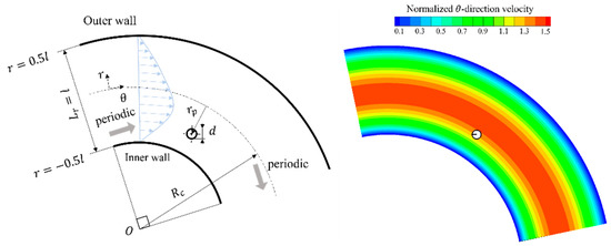
Figure 1.
Schematic view of curvilinear channel.
The channel width was set to 200 μm, the diameter of the particle was set to 20–50 μm, and the Reynolds number was set to 16–64. Importantly, this analysis does not consider the effects of secondary flows caused by curvilinear flows because of two-dimensional geometry or collisions between particles because of single-particle flow. In addition, we employed the particle’s center of gravity as the evaluation of particle position in the channel.
2.2. Governing Equations
For the equation of the flow, we used the regularized lattice Boltzmann method [42,43] (2D9V model), which is a modified version of the lattice Boltzmann method. The original method was modified to reduce its memory usage and increase its computing stability.
The advection and collision of virtual particles were considered to express the distribution function due to the discrete velocity vector of the lattice Boltzmann equation. When expanded up to the second-order moment, the distribution function can be evaluated as incompressible Navier-Stokes equations and is expressed as Equation (7). In this study, moments were used up to second order to obtain sufficient accuracy based on gas molecular kinetics.
where the parameters , , and are moments in the distribution function and satisfy the following relationships:
where denotes fluid density, denotes momentum, and denotes the nonequilibrium component of the stress tensor. As shown in Equation (8), the Taylor expansion of Maxwell’s equilibrium distribution function to the second order series can be used to obtain the nonequilibrium distribution function [49,50].
Therefore, the time evolution equation for the lattice Boltzmann equation is given by
where denotes the relaxation time, which was set to 0.80 for the simulations. The relaxation time is defined by the Chapman-Enskog expansion so as to be consistent with the Navier-Stokes equation, as follows:
where denotes kinematic viscosity.
In this study, the pressure distribution function proposed by He et al. [44] was adopted in order to treat the working fluid as an incompressible fluid, and an incompressible formulation was applied. Then, the local pressure distribution function was defined using the density distribution function , as follows:
where denotes the speed of sound, with in this model. Therefore, the pressure , velocity components , and the nonequilibrium component of the stress tensor are expressed as follows:
Therefore, the time evolution equation is given as:
2.3. Governing Equations for Particle Movements
In this study, we have discussed the relationship between the behavior of suspended small particles in the fluid and macroscopic flow characteristics by considering the interaction between the particles and the fluid. Therefore, the particle-fluid interaction was considered to use the two-way coupling scheme [45] due to the translational and rotational motions of the particles. The motions of finite-size particles obeyed Newton’s second law for translation and the angular equation of motion for rotation. In addition, the particle conditions included neutrally buoyant particles and non-Brownian motions.
where denotes the external force vector, denotes particle mass, denotes the position vector, denotes torque, denotes the moment of inertia, and denotes the particle angle. The external force vector acting on the particles was calculated from the hydrodynamic forces around the particle, as expressed by the third-order Adams-Bashforth method of the tertiary system. Therefore, the velocity vector and component of velocity for - system were expressed as follows:
where denotes particle density, and and denote the velocity component of radial direction position and theta direction position, respectively. and denote the components of the radial direction unit vector, while and denote the components of the theta direction unit vector. was set to 0 when fixing the radial direction of the particle movement to evaluate the lift force acting on the particles [51]. In addition, the lift coefficient is expressed as follows:
where denotes the characteristic velocity for , and denotes the characteristic length.
2.4. Virtual Flux Method
In this study, the VFM [46,47,48] was used to represent arbitrarily shaped objects of particles and curved channel walls. This method analyzes the flow field around an arbitrarily shaped object on a cartesian grid. VFM can calculate the flow field around a particle and the flow phenomena inside the particle simultaneously. In addition, VFM is associated with ease of implementation and high computational efficiency [48]. This method can capture the pressure field around the object with high accuracy, although the curves of a virtual object are difficult to represent on a cartesian grid. A schematic diagram of the virtual flux method for a particle is shown in Figure 2.
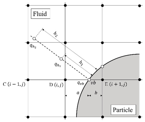
Figure 2.
Schematic view of the VFM for a particle. and are internal division ratios across the virtual boundary. is the physical quantity on virtual boundary point.
In the 2D9V model of RLBM, a virtual boundary point must be placed at the intersection of the 8-directional discrete velocity and the particle surface when the 8-directional discrete velocity vector straddles the boundary of the object surface. In this analysis, the non-slip boundary condition was employed as the boundary condition of the body surface. Velocities on virtual boundary points are provided as () in order to satisfy the non-slip boundary condition on body surfaces, where is the velocity vector on the wall surface of the body surface. Pressures on virtual boundary point are calculated under the Nuemann boundary condition (), which is an approximate pressure condition on the body surface. In reference to Figure 2, the case where the distribution function at point moves to point across the virtual boundary is considered so as to determine the distribution function at point in the next time step. However, the distribution function at point cannot move to point because a virtual boundary separates the fluid from the particles. Therefore, we obtain the virtual distribution function at point from the distribution function at the virtual boundary point “”. The physical quantity on the virtual boundary point is used to obtain the equilibrium distribution function at the virtual boundary point (Equation (21)):
Therefore, the distribution function on the virtual boundary point is expressed as follows:
Finally, the virtual distribution function and the equilibrium distribution function at point are calculated by linear extrapolation using the internal division ratios and .
Therefore, the fluid and particles shown in Figure 2 can be calculated independently.
The equilibrium distribution function at the object surface is expressed as shown below because this analysis adopts the pressure distribution function proposed by He and Luo [44]:
where denotes pressure on the virtual boundary point and is calculated by extrapolating from the pressures and at the points separated from the boundary point by distances and in the direction normal to the wall surface.
where the pressures at points and are interpolated with weights from the surrounding four grid points, and and are set to and times the grid width, respectively.
2.5. Periodic Boundary Condition
The particles need to flow a sufficient distance to reach the equilibrium position, when performing pressure-driven flow in two-dimensional curvilinear channels. Therefore, the periodic boundary condition [45] was applied to reduce the computational costs. In a flow field driven by pressure difference, the pressure difference is caused by flowing pressure-driven over the channel length to be in kinetic balance with the hydrodynamic forces along the flow direction.
where denotes the flow direction component of the fluid force (-direction for a curvilinear channel), and denotes the channel length. is determined by the viscous forces of flow direction acting on the channel walls and particle surfaces, as follows:
where and denote the shear stress of the upper and lower walls of the channel (the outer and inner walls in a curvilinear channel, respectively), and denotes the drag coefficient of each particle. The resulting pressure drop is considered to be in the flow direction in order to realize periodic boundary conditions. In this study, the pressure drop was calculated step by step by multiplying the pressure drop in the previous time step by a correction term using the flow rate ratio.
where denotes pressure drop caused by drag forces acting on the particle and wall shear stress, denotes the theoretical volume flow rate calculated using the characteristic velocity and the channel width , and denotes the average volume flow rate obtained by numerical solution in the channel.
3. Results and Discussion
3.1. Velocity Profiles in Curvilinear Channel
First, the dependence of eccentricity and Reynolds number on the velocity distributions in a curvilinear channel was investigated. The characteristic velocity was used to normalize the velocity profiles.
The velocity distribution in the channel approaches that for a straight channel with the increase in the radial length of curvature (Figure 3a). Our findings showed that the normalized velocity distribution in the curvilinear channel was independent of (Figure 3b). In a two-dimensional straight parallel-plate flow, the mechanical equilibrium position of a particle is generally considered to be three points: the channel center, where the shear rate , and two points axisymmetric to the channel center. Therefore, the point of shear rate should be considered when examining the mechanical equilibrium position in a curvilinear channel. Table 1 shows the radial direction position where the velocity gradient .
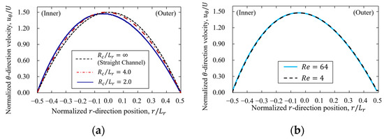
Figure 3.
Velocity profiles of curvilinear channel with . (a) Difference in velocity profiles between curvilinear channel and straight channel with . (b) Reynolds number dependence using .

Table 1.
Shear rate at each radial length of curvature and location where .
3.2. Validation
In this study, the dependence of the particle equilibrium position in a curvilinear channel on the radial length of curvature was investigated to physically validate the calculation results. As suggested in Section 3.1, the flow field in a curvilinear channel approached the straight channel with the increase in the radial length of curvature . Thus, the equilibrium position of the particle in a curvilinear channel is also expected to approach that of the straight channel. Accordingly, we compared the final particle equilibrium position with increasing radial length of curvature to the equilibrium position in a straight channel and discussed the same in Section 3.3 and thereafter.
3.2.1. Equilibrium Position of Particle in Straight Channel
The analysis model of a straight channel is shown in Figure 4, and the equilibrium position of the particle and the results for others are shown in Table 2.
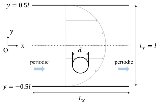
Figure 4.
Computational model of straight channel.
Table 2.
Equilibrium position in straight channel with for and .
Here, denotes the periodic length. The computational domain is . The confinement , and the Reynolds number . Table 2 shows the equilibrium positions of the particle and the results for others with respect to the varying values of . Table 2 shows that the equilibrium positions in the straight channel are consistent with the results of Inamuro [52]. Thus, it enabled the evaluation of the physical validity of the analysis of the straight channel.
The appropriate periodic length needs to be considered when using periodic boundary conditions to evaluate the particle equilibrium position. The periodic length is required to be sufficient for analysis as a single particle because the periodic length in the periodic boundary condition is related to the particle-particle interaction. Therefore, we investigated the dependence of the equilibrium position on the periodic length. The relationships between the periodic length and particle-particle interaction are shown in Figure 5. In this case, the initial position of the particle in the straight channel, is set to −0.30 in order to compare the results of the equilibrium position in the straight channel with that in the curvilinear channel. In addition, the periodic length, which is expressed as the ratio of channel width to particle diameter , was varied, i.e., .
Figure 5.
Examination of periodic length. (a) Schematic of relationship between particle-particle distance and periodic length. (b) Relationship between equilibrium position of particle and periodic length with , and C = 0.25.
Figure 5b shows that the equilibrium position of the particle was constant after . Therefore, the periodic boundary condition requires a periodic length of about 16 times as long as the diameter of the particle to consider it a single particle. In addition, the equilibrium position of particle in the straight channel for and was equal to −0.214.
3.2.2. Radial Length of Curvature Dependence
Next, the relationship between the final equilibrium position of the particles and the radius length of curvature was investigated based on the equilibrium position in the straight channel obtained in Section 3.2.1. Then, the initial position of the particles was set below the channel center (inner wall side). Figure 6 shows the trends of the equilibrium positions of particles in the curvilinear channel with varying radial lengths of curvature.
Figure 6.
Segré–Silberberg effects at each radial length of curvature for cells, and and equilibrium position of particle in straight channel .
Table 3 shows the values of the equilibrium positions of particles in the curvilinear channel with varying radial lengths of curvature. As shown in Section 3.2.1, the equilibrium position in the curvilinear channel approached the equilibrium position in the straight channel when the radial length of curvature increased. In addition, the particle equilibrium positions in the curvilinear channel and in the straight channel were sufficiently small for . These results showed that the mechanical environments, such as velocity profiles and lift forces, acting on particles in the curvilinear channel approached those in the straight channel by increasing .
Table 3.
Equilibrium position at each radial length of curvature and periodic channel length.
3.3. Verification
In this study, we investigated the resolution dependence of the particle equilibrium positions for the numerical validity of the calculation results. The resolution was verified for and , which required the highest resolution among the parameters used in this study. The relationships between the equilibrium position of the particle and the resolution are shown in Figure 7, and the values of the final equilibrium position for each resolution are shown in Table 4.
Figure 7.
Relationships between the equilibrium position of the particle and the resolution at inner wall side for and .
Table 4.
Value of equilibrium position of particle at each number of grids of channel width and particle diameter at inner wall side for and .
Table 4 shows that the equilibrium position with increasing resolution was constant after . In this study, as an appropriate resolution, we adopted for the evaluation of the equilibrium position.
3.4. Segré–Silberberg Effects
3.4.1. Segré–Silberberg Effects at Different Initial Positions
Figure 8 shows the particle behavior flowing from different initial positions in a curvilinear channel, as well as the position and velocity of particles flowing at . In addition, the values of the initial position of the particle and the particle position at time are shown in Table 5.
Figure 8.
Segré–Silberberg effects at different initial positions for and . (a) Time history of particle behavior for 100 non-dimensional time. (b) Particle position at in asymmetric velocity profiles, and theoretical velocity profiles of straight channel .
Table 5.
Value of initial particle position and particle position at .
The equilibrium position of particles in axisymmetric flow profiles, such as flow between parallel plates, is symmetric with respect to the channel center, i.e., the equilibrium position is at a point of equal distance from the channel center [11,12]. However, the final equilibrium radial position of particles in asymmetric velocity profiles converged differently between the outer wall and inner wall sides with respect to the channel center (Figure 8 and Table 5). In addition, the particle was observed to move to the outer equilibrium position due to eccentricity when the channel center was taken as the initial position. These results suggest that the microstructural changes in a curvilinear channel are asymmetric with respect to the channel center. The particle-wall distance of the dispersing particles is suggested to play a key role in determining the macroscopic viscosity properties [26]. Therefore, an asymmetric velocity profile changes the equilibrium position, and consequently, an asymmetric microstructure with respect to the channel axis may change the macroscopic suspension viscosity.
3.4.2. Lift Force Acting on the Particle Which Reached Equilibrium Position
Figure 9 shows the lift force acting on a particle for its inner wall side equilibrium position and the centrifugal force estimated using particle mass, radial position, and orbital angular velocity.
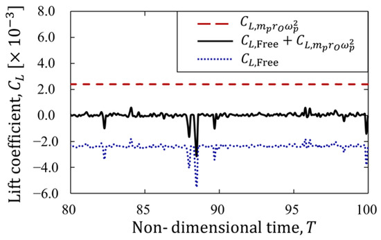
Figure 9.
Lift force acting on the particle for its inner wall side equilibrium position for and from 80 to 100 non-dimensional time.
The centrifugal force approximated with a particle as the mass point is expressed as:
where denotes particle mass as a mass point, denotes radial distance from center of revolution, and denotes orbital speed. In Figure 9, denotes the lift coefficient acting on a buoyant-free particle, and denotes the lift coefficient of centrifugal force calculated at equilibrium position using Equation (30). In general, the particle in its equilibrium position is expected to have equal to 0 due to the force balance. However, a certain negative lift force acted on particles in the curvilinear channel. Therefore, we compared the value with the centrifugal force calculated from Equation (30) and found that it was equal to the lift force acting on the particles (Figure 9). This suggested that the particles in the curvilinear channel were subjected to a centripetal force equal to the centrifugal force.
3.4.3. Evaluation of Equilibrium Position by Lift Force Considering Centrifugal Force
The lift force acting on the particles at each radial position was calculated to quantitatively evaluate the mechanical equilibrium position of the particles. The distribution of the lift force acting on the particles at each radial position is shown in Figure 10.
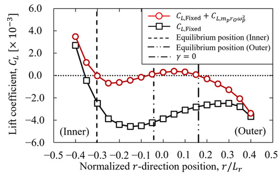
Figure 10.
Lift coefficient acting on the particle for and .
In Figure 10, denotes the lift coefficient acting on the particle obtained by fixing its radial direction movement at each radial direction position, while denotes the lift coefficient of centrifugal force calculated using Equation (30). As shown in the figure, there are three points where the mechanical equilibrium position of the particle () is reached when correcting the centrifugal force, considering the centripetal force subjected to the particle. These three mechanical equilibrium positions matched the two equilibrium positions at the inner and outer walls (presented in Section 3.4.2) and the shear rate of 0 (presented in Section 3.1). These results suggest that the equilibrium position using lift forces can be quantitatively evaluated in terms of a mechanical equilibrium position by considering centrifugal forces. In addition, the centrifugal forces acting on the particle should be considered when evaluating the equilibrium position for particle flow in a curvilinear channel.
3.5. Particle Migration
As shown in the previous Section 3.4.1, particles flowing in the curvilinear channel move to asymmetric equilibrium positions on the inner and outer wall sides. This finding suggests that the microstructure of the suspension flowing through the curvilinear channel is asymmetric with respect to the channel center. In addition, the inertial forces and particle-fluid interactions in the curvilinear channel are asymmetric on the inner and outer wall sides in the case of asymmetric mechanical equilibrium positions. We investigated the changes in equilibrium position due to changes in particle inertia and particle size so as to consider the mechanical factors that determine the equilibrium position of particles. Particle behavior and final particle position for varying confinement are shown in Figure 11 and Table 6, and those for varying Reynolds numbers Re are shown in Figure 12 and Table 7. The lift force acting on the particle at each radial position is presented in Figure 13.
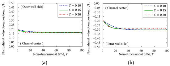
Figure 11.
Particle migration for varying confinement with . (a) Particle migration on outer wall side. (b) Particle migration on inner wall side.
Table 6.
Value of particle position at for varying confinement with .
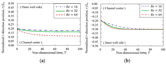
Figure 12.
Particle migration for varying Reynolds number with . (a) Particle migration on outer wall side. (b) Particle migration on inner wall side.
Table 7.
Value of particle position at for varying Reynolds number with .
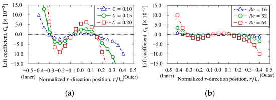
Figure 13.
Inertial lift force acting on the particle at each -direction position. (a) confinement dependence. (b) Reynolds number dependence.
In general, the equilibrium position of particles in a straight channel is discussed in terms of the balance of mechanical forces, mainly the lift force acting on finite-size particles due to the velocity gradient and the repulsive force between the particle and the wall. Previous studies have suggested that the particle equilibrium position moves to the center of the channel with the increase in the repulsive force from the wall surface due to the increase in particle size [52]. In addition, the particles move in the direction of the wall surface when the Reynolds number increases because of the increase in the lift force in the direction of the wall acting on finite-size particles caused by the increase in velocity gradient [13]. However, the inner and outer walls of a two-dimensional curvilinear channel were found to yield asymmetric equilibrium positions with respect to the channel center. These results suggested that there are other factors in addition to the velocity gradient and the repulsive force from the wall that determine the equilibrium position. This is because the equilibrium position on the outside of the channel does not move toward the channel center (Figure 11a).
Figure 11a shows the times history of particle migration on the outer wall for varying confinement . Due to the increased repulsive force from the wall surface, the equilibrium positions were expected to shift toward the channel center. However, there was no significant change in particle equilibrium position with respect to the confinement effect. The equilibrium position did not change because the increase in wall repulsive force due to the increase in confinement was offset by the centrifugal force in the opposite direction. In Figure 11b, the equilibrium position was expected to move toward channel center with the increase in confinement. Then, the direction of the centrifugal force was also channeled centerward, as was the repulsive force from the channel wall. Therefore, the equilibrium position of particle shifted to the channel center. In Figure 12b, the particle was expected to move to the channel wall side (inner wall side) with the increase in . However, the particle was expected to move to channel center due to the centrifugal force because the direction of centrifugal force was channel center-ward. In this case, we considered that the equilibrium position had not changed significantly since the forces for wall surface direction caused by increasing inertial force and centrifugal force acting on the particle were offset.
In Figure 12a, it is difficult to consider the equilibrium position due to centrifugal forces. The changes in equilibrium position are expected to shift to the channel wall direction (outer wall), given the assumption that the equilibrium position was determined predominantly by centrifugal force. In this simulation, the change in equilibrium position caused by increasing was also in the channel wall direction (outer wall). Therefore, the equilibrium position of particles was expected to shift in the channel wall direction. However, Figure 12a shows that the particle equilibrium position shifted to the center of the channel when increased, which was the opposite of the above expectation. This is because of the change in velocity gradient due to the eccentricity of the flow field.
Figure 13b shows the lift distribution acting on the particles at each radius direction position when centrifugal force is considered, using the same method as in Section 3.4.3. As shown in Figure 13, the change in lift force with increasing might be attributed to the repulsive force from the wall and the inertia force due to the velocity gradient, taking centrifugal forces into account. Near the center of the channel on the outer wall side, the lift force acting on the particles in the direction of the wall (outer wall) was independent of the increase in . This was expected because the velocity gradient on the outer wall was relatively gentle, which reduced the amount of increase in the wall direction force as the Reynolds number changed. In contrast, the lift force near the outer wall in the direction of the channel center increased with the increase in . We considered that the repulsive force from the channel became dominant since the repulsive force from the channel wall was increased due to the increase in . Therefore, the change in these two mechanical factors may change the mechanical balance between the velocity gradient and the repulsive force from the wall, causing the particles to shift to the channel center. This indicates the importance of the effect of changes in the velocity field in the determination of the equilibrium position of particles at the outer wall over that due to centrifugal forces.
4. Conclusions
In this study, particle migration in an asymmetric velocity field was investigated using a two-dimensional pressure-driven flow in a curvilinear channel. The particles took asymmetric equilibrium positions with respect to the channel center. These results suggested that an asymmetric velocity profile changes the equilibrium position of the particles, and consequently, an asymmetric microstructure may change the macroscopic suspension viscosity.
Author Contributions
Conceptualization, R.N. and T.F.; methodology, R.N. and T.F.; software, R.N. and T.F.; validation, R.N.; formal analysis, R.N.; investigation, R.N.; resources, T.F.; data curation, R.N.; writing—original draft preparation, R.N.; writing—review and editing, R.N. and T.F.; visualization, R.N.; supervision, T.F.; project administration, T.F.; funding acquisition, T.F. All authors have read and agreed to the published version of the manuscript.
Funding
This work was supported in part by JSPS KAKENHI grant number JP20K04266.
Data Availability Statement
Data sharing is not applicable.
Conflicts of Interest
The authors declare no conflict of interest.
References
- Rebouças, R.; Siqueira, I.; Mendes, P.D.S.; Carvalho, M. On the pressure-driven flow of suspensions: Particle migration in shear sensitive liquids. J. Non-Newton. Fluid Mech. 2016, 234, 178–187. [Google Scholar] [CrossRef]
- Doyeux, V.; Priem, S.; Jibuti, L.; Farutin, A. Effective viscosity of two-dimentional suspension: Confinement effects. Phys. Rev. Fluids 2016, 4, 43301. [Google Scholar] [CrossRef]
- Chen, S.-D.; Pan, T.-W.; Chang, C.-C. The motion of a single and multiple neutrally buoyant elliptical cylinders in plane Poiseuille flow. Phys. Fluids 2012, 24, 103302. [Google Scholar] [CrossRef]
- Wen, B.; Chen, H.; Qin, Z.; He, B.; Zhang, C. Lateral migration and nonuniform rotation of suspended ellipse in Poiseuille flow. Comput. Math. Appl. 2019, 78, 1142–1153. [Google Scholar] [CrossRef]
- Thomas, D.G. Transport characteristics of suspension: VIII. A note on the viscosity of Newtonian suspensions of uniform spherical particles. J. Colloid Sci. 1965, 20, 267–277. [Google Scholar] [CrossRef]
- Mueller, S.; Llewellin, E.; Mader, H.M. The rheology of suspensions of solid particles. Proc. R. Soc. A Math. Phys. Eng. Sci. 2009, 466, 1201–1228. [Google Scholar] [CrossRef]
- Stickel, J.J.; Powell, R.L. Fluid Mechanics and Rheology of Dense Suspensions. Annu. Rev. Fluid Mech. 2005, 37, 129–149. [Google Scholar] [CrossRef]
- Morris, J.F. A review of microstructure in concentrated suspensions and its implications for rheology and bulk flow. Rheol. Acta 2009, 48, 909–923. [Google Scholar] [CrossRef]
- Einstein, A. Eine neue Bestimmung der Moleküldimensionen. Ann. Phys. 1906, 324, 289–306. [Google Scholar] [CrossRef]
- Brady, J.F. The Einstein viscosity correction in n dimensions. Int. J. Multiph. Flow 1984, 10, 113–114. [Google Scholar] [CrossRef]
- Segré, G.; Silberberg, A. Radial Particle Displacements in Poiseuille Flow of Suspensions. Nature 1961, 189, 209–210. [Google Scholar] [CrossRef]
- Segré, G.; Silberberg, A. Behavior of macroscopic rigid sphere in Poiseuille flow Part. 2. Experimental results and inter-pretation. J. Fluid Mech. 1962, 14, 136–157. [Google Scholar] [CrossRef]
- Matas, J.-P.; Morris, J.F.; Guazzelli, É. Inertial migration of rigid spherical particles in Poiseuille flow. J. Fluid Mech. 2004, 515, 171–195. [Google Scholar] [CrossRef]
- Matas, J.P.; Morris, J.F.; Guazzelli, É. Lateral force on a sphere. Oil Gas Sci. Technol. 2004, 59, 59–70. [Google Scholar] [CrossRef]
- Seo, K.W.; Kang, Y.J.; Lee, S.J. Lateral migration and focusing of microspheres in a microchannel flow of viscoelastic fluids. Phys. Fluids 2014, 26, 63301. [Google Scholar] [CrossRef]
- Feng, J.; Hu, H.H.; Joseph, D.D. Direct simulation of initial value problems for the motion of solid bodies in a Newtonian fluid. Part 2. Couette and Poiseuille flows. J. Fluid Mech. 1994, 277, 271–301. [Google Scholar] [CrossRef]
- Yang, B.H.; Wang, J.; Joseph, D.D.; Hu, H.H.; Pan, T.-W.; Glowinski, R. Migration of a sphere in tube flow. J. Fluid Mech. 2005, 540, 109–131. [Google Scholar] [CrossRef]
- Liu, W.; Wu, C. Amalysis of inertial migration of neutrally buoyant particle suspension in planar Poiseuille flow with a coupled lattice Boltzmann method-discrete element method. Phys. Fluids 2019, 31, 063301. [Google Scholar]
- Asmolov, E.S. The inertial lift on a spherical particle in a plane Poiseuille flow at large channel Reynolds number. J. Fluid Mech. 1999, 381, 63–87. [Google Scholar] [CrossRef]
- Schonberg, J.A.; Hinch, E.J. Inertial migration of a sphere in Poiseuille flow. J. Fluid Mech. 1989, 203, 517–524. [Google Scholar] [CrossRef]
- Di Carlo, D.; Edd, J.F.; Humphry, K.J.; Stone, H.A.; Toner, M. Particle Segregation and Dynamics in Confined Flows. Phys. Rev. Lett. 2009, 102, 094503. [Google Scholar] [CrossRef] [PubMed]
- Fukui, T.; Kawaguchi, M.; Morinishi, K. Numerical study on the inertial effects of particles on the rheology of a suspension. Adv. Mech. Eng. 2019, 11, 1687814019847000. [Google Scholar] [CrossRef]
- Okamura, N.; Fukui, T.; Kawaguchi, M.; Morinishi, K. Influence of each cylinder’s contribution on the total effective viscosity of a two-dimensional suspension by a two-way coupling scheme. J. Fluid Sci. Technol. 2021, 16, JFST0020. [Google Scholar] [CrossRef]
- Fukui, T.; Kawaguchi, M. Numerical study of microscopic particle arrangement of suspension flow in a narrow channel for the estimation of macroscopic rheological properties. Adv. Powder Technol. 2022, 33, 103855. [Google Scholar] [CrossRef]
- Liu, J.; Li, C.; Ye, M.; Liu, Z. On the shear viscosity of dilute suspension containing elliptical porous particles at low Reynolds number. Powder Technol. 2019, 354, 108–114. [Google Scholar] [CrossRef]
- Kawaguchi, M.; Fukui, T.; Morinishi, K. Contribution of Particle–Wall Distance and Rotational Motion of a Single Confined Elliptical Particle to the Effective Viscosity in Pressure-Driven Plane Poiseuille Flows. Appl. Sci. 2021, 11, 6727. [Google Scholar] [CrossRef]
- Li, H.; Ma, G. Modeling performance of a two-dimensional capsule in a microchannel flow: Long-term lateral migration. Phys. Rev. E 2010, 82, 026304. [Google Scholar] [CrossRef]
- Rezghi, A.; Li, P.; Zhang, J. Lateral migration of viscoelastic capsules in tube flow. Phys. Fluids 2022, 34, 11906. [Google Scholar] [CrossRef]
- Feng, H.; Huang, H.; Lu, X.-Y. Rheology of capsule suspensions in plane Poiseuille flows. Phys. Fluids 2021, 33, 13302. [Google Scholar] [CrossRef]
- Lázaro, G.R.; Hernández-Machado, A.; Pagonabarraga, I. Rheology of red blood cells under flow in highly confined micro-channels: Ⅰ. effect of elasticity. Soft Matter. 2014, 10, 7195–7206. [Google Scholar] [CrossRef]
- Lázaro, G.R.; Hernández-Machado, A.; Pagonabarraga, I. Rheology of red blood cells under flow in highly confined micro-channels. Ⅱ. Effect of focusing and confinement. Soft Matter. 2014, 10, 7207–7217. [Google Scholar] [CrossRef] [PubMed]
- Zhang, J.; Johnson, P.C.; Popel, A.S. Red blood cell aggregation and dissociation in shear flows simulated by lattice Boltzmann method. J. Biomech. 2008, 41, 47–55. [Google Scholar] [CrossRef] [PubMed]
- Ghigliotti, G.; Biben, T.; Misbah, C. Rheology of a dilute two-dimensional suspension of vesicles. J. Fluid Mech. 2010, 653, 489–518. [Google Scholar] [CrossRef]
- Hu, X.; Ku, X. Inertial migration of circular particles in Poiseuille flow of a power-law fluid. Phys. Fluids 2019, 31, 73306. [Google Scholar] [CrossRef]
- Chrit, F.E.; Bowie, S.; Alexeev, A. Inertial migration of spherical particles in channel flow of power law fluids. Phys. Fluids 2020, 32, 83103. [Google Scholar] [CrossRef]
- Vaira, N.J.D.; Łaniewski-Wołłk, Ł.; Johnson, R.L., Jr.; Aminossadati, S.M.; Leonardi, C.R. Influence of particle polydispersity on bulk migration and size segregation in channel flows. J. Fluid Mech. 2022, 939, 1–32. [Google Scholar] [CrossRef]
- Kumar, A.; Graham, M.D. Margination and segregation in confined flows of blood and other multicomponent suspensions. Soft Matter. 2012, 8, 10536–10548. [Google Scholar] [CrossRef]
- Chun, B.; Park, J.S.; Jung, H.W.; Won, Y.-Y. Shear-induced particle migration and segregation in non-Brownian bidisperse suspensions under planar Poiseuille flow. J. Rheol. 2019, 63, 437–453. [Google Scholar] [CrossRef]
- Liu, W.; Wu, C.-Y. Inertial migration of a neutrally buoyant circular particle in a planar Poiseuille flow with thermal fluids. Phys. Fluids 2021, 33, 63315. [Google Scholar] [CrossRef]
- Zhang, J.; Zhang, X.; Wang, N.; Liu, H.; Xi, G. Lattice Boltzmann modeling of particle dynamics in rotating coordinate system. Phys. Fluids 2021, 33, 123316. [Google Scholar] [CrossRef]
- Ho, B.P.; Leal, L.G. Inertial migration of rigid spheres in two-dimensional unidirectional flows. J. Fluid Mech. 1974, 65, 365–400. [Google Scholar] [CrossRef]
- Morinishi, K.; Fukui, T. Parallel computation of turbulent flows using moment base lattice Boltzmann method. Int. J. Comput. Fluid Dyn. 2016, 30, 363–369. [Google Scholar] [CrossRef]
- Izham, M.; Fukui, T.; Morinishi, K. Application of Regularized Lattice Boltzmann Method for Incompressible Flow Simulation at High Reynolds Number and Flow with Curved Boundary. J. Fluid Sci. Technol. 2011, 6, 812–822. [Google Scholar] [CrossRef]
- He, X.; Luo, L.S. Lattice Boltzmann model for the incompressible Navier stokes equation. J. Stat. Phys. 1997, 88, 927–944. [Google Scholar] [CrossRef]
- Fukui, T.; Kawaguchi, M.; Morinishi, K. A two-way coupling scheme to model the effects of particle rotation on the rheological properties of a semidilute suspension. Comput. Fluids 2018, 173, 6–16. [Google Scholar] [CrossRef]
- Morinishi, K.; Fukui, T. An Eulerian approach for fluid–structure interaction problems. Comput. Fluids 2012, 65, 92–98. [Google Scholar] [CrossRef]
- Tanno, I.; Morinishi, K.; Matsuno, K.; Nishida, H. Validation of Virtual Flux Method for Forced Convection Flow. JSME Int. J. Ser. B 2006, 49, 1141–1148. [Google Scholar] [CrossRef]
- Kawaguchi, M.; Fukui, T.; Morinishi, K. Comparative study of the virtual flux method and immersed boundary method coupled with regularized lattice Boltzmann method for suspension flow simulations. Comput. Fluids 2022, 246, 105615. [Google Scholar] [CrossRef]
- He, X.; Luo, L.-S. A priori derivation of the lattice Boltzmann equation. Phys. Rev. E 1997, 55, R6333–R6336. [Google Scholar] [CrossRef]
- He, X.; Luo, L.-S. Theory of the lattice Boltzmann method: From the Boltzmann equation to the lattice Boltzmann equation. Phys. Rev. E 1997, 56, 6811–6817. [Google Scholar] [CrossRef]
- Udono, H.; Sakai, M. Numerical Evaluation of Lift Forces Acting on a Solid Particle in a Microchannel. J. Soc. Powder Technol. Jpn. 2017, 54, 454–459. [Google Scholar] [CrossRef]
- Inamuro, T.; Maeba, K.; Ogino, F. Flow between parallel walls containing the lines of neutrally buoyant circular cylinders. Int. J. Multiph. Flow 2000, 26, 1981–2004. [Google Scholar] [CrossRef]


Disclaimer/Publisher’s Note: The statements, opinions and data contained in all publications are solely those of the individual author(s) and contributor(s) and not of MDPI and/or the editor(s). MDPI and/or the editor(s) disclaim responsibility for any injury to people or property resulting from any ideas, methods, instructions or products referred to in the content. |
© 2023 by the authors. Licensee MDPI, Basel, Switzerland. This article is an open access article distributed under the terms and conditions of the Creative Commons Attribution (CC BY) license (https://creativecommons.org/licenses/by/4.0/).