Abstract
This paper presents an unsteady coupled heat transfer model in mine air and surrounding rock mass in the presence of distributed heat sources. The case of distributed heat sources is typical when analyzing the temperature distribution in mine excavations equipped with conveyor systems. For this case, the asymptotic value of the air temperature at the end of the mine excavation is determined not only by the heat exchange between the air and surrounding rock mass but also by the thermal power of distributed heat sources and the total airflow. This conclusion is confirmed by the experimental data presented in the paper for a longwall in a potash mine. We formulate the mathematical model and calculate the distribution of air parameters along the length of an excavation, considering heat release from the conveyor and surrounding rock mass. The results show that a distributed heat release is necessary for correctly calculating the air temperature in working areas. The numerical simulations allow us to recommend a redistribution of air between the haulage and conveyor roadways in the presence of distributed heat sources.
1. Introduction
The air temperature in mine excavation depends on many factors, which can be divided into two types—the heat exchange of air with the rock mass and the heat exchange due to heat sources/sinks. The nature of the problem under study determines how detailed the factors of the first type should be. The simplest approach is to set boundary conditions of the first, second, or third kind on the excavation wall without considering the heat propagation in the rock mass. Boundary conditions of the first kind are also called Dirichlet conditions, boundary conditions of the second kind are also called Neumann conditions, and boundary conditions of the third kind can be called mixed or convective conditions. A more complex approach considers heat transfer in both the air and surrounding rock mass in a coupled formulation [1,2].
The simplest approach is appropriate and has an insignificant error in limiting cases for short and long simulation times. In the first case, when thermal contact between air and the rock mass is short (on the order of several hours), the rock mass at the air boundary does not have time to change temperature significantly. For this reason, the heat exchange of air with the rock mass is specified using the convective boundary condition of the third kind, and the heat transfer in the rock mass is not investigated. With thermal insulation near the mine excavation, a boundary condition of the second kind is set to a zero value for the heat flux on the wall. In another limiting case, when—after a long time with a nearly unchanged air temperature distribution along the length of the mine excavation—temperature changes propagate deep into the rock mass, the boundary condition of the first kind with the equality of air and rock mass temperatures is acceptable.
If the specifics of the problem do not correspond to the limiting cases above, then the problem should be solved in a coupled formulation, considering the variation of the temperature field in the rock mass. It is also possible to use a simplified model based on the “nonstationary heat transfer coefficient”. This coefficient implicitly considers the change in temperature of the rock mass near the mine excavation with time [3]. At the same time, the excavation wall’s temperature at the initial time is presented in the boundary condition of the heat balance between the air and the rock mass.
To predict temperature changes in ventilation air as it moves through the systems of mine excavations, it is also necessary to know the factors of the second type associated with heat sources and sinks. After the air is supplied to the mine through the air supply shaft, the temperature begins to change—both due to heat exchange with the rock mass and incoming heat of natural and artificial origin. Natural processes include the heating and cooling of air in the vertical mine shaft due to hydrostatic compression and expansion, evaporation and condensation of moisture, and heat release during oxidative processes and combustion. The artificial heat sources include heating and air conditioning units and mining equipment that generates heat.
Accounting for artificial sources of heat release is especially important if they are located along the air path near the working areas since, in this case, they can affect the temperature of the air supplied to ventilate the working areas [4]. Most often, this temperature is determined by the natural temperature of the rock mass, which it approaches due to heat transfer. Local sources of heat release affect the air parameters only at small distances since local air heating is quickly leveled by the heat exchange process. However, the situation changes in the presence of distributed heat sources such as conveyor systems. The results of the experimental measurements given below show a significant influence of this factor on air temperature.
The novelty of the study lies in solving the problem of coupled heat transfer in the mine air and rock mass in the presence of a distributed heat source. Traditionally, the problem of heat transfer is limited by the influence of point sources [2,4,5]. This usually comes down to setting the appropriate boundary conditions for the incoming air temperature; then the air temperature changes due to heat and mass transfer processes. In this study, the final air temperature at short and long times was of interest under the simultaneous action of both factors.
2. Experimental Study
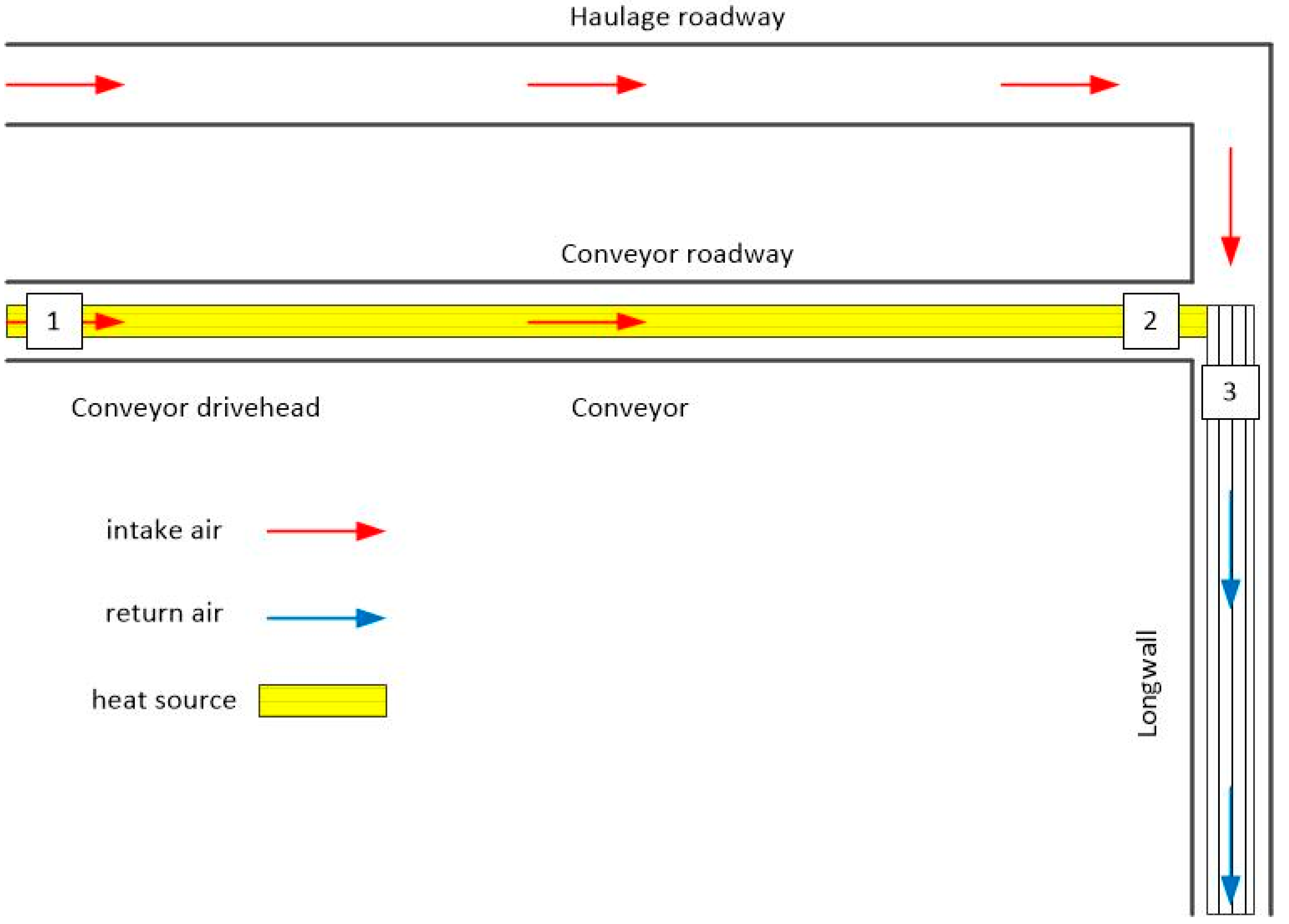
The experimental study was carried out in the conditions of the potash mines of the “Belaruskali” company. The object of study is part of a large mine and includes several mine excavations (tunnels). The cross-section area of excavations has a constant value along the length of the excavations. Schematically, the object of study is shown in Figure 1. A fresh air stream enters through the haulage and conveyor roadways to a longwall, and the contaminated air leaves the working zone of the longwall through the ventilation drift. The length of these excavations can reach 5000 m, while the conveyor roadway is equipped with belt conveyors, along which the mined potash ore is transported. Throughout the measurements, the total airflow supplied through the excavations, the wall temperature, and the final air temperature supplied to ventilate the longwall were measured. Table 1 presents the experimental results and the difference between the final air and rock temperatures. This value is attributed to the heat released from the conveyors.
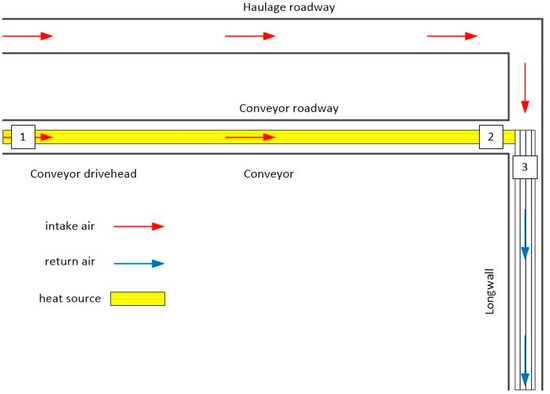
Figure 1.
Schematic representation of the air supply along the haulage and transport roadways to a long stope.

Table 1.
Air temperature measurements at the end of the conveyor roadway.
The heat distribution from the conveyor was nearly uniform along the length of the excavations since all the energy consumed by the conveyor’s drive is dissipated along the length of the drift to overcome friction forces. In addition, we observed that conveyor lines operate on average for about half of the shift time, so the effective operating time of the heat source must be considered in the calculations.
Thus, the final air temperature during its movement along two air supply roadways is formed due to the action of two factors—air heat exchange in the rock mass and distributed heat sources. Next, a mathematical model was developed to predict the unsteady temperature distribution considering these factors.
3. Mathematical Model
This section describes a heat transfer model in the atmosphere of the conveyor roadway. The conveyor belt is considered a uniformly distributed heat source along the excavation length. The conveyor operating time is assumed to be arbitrary. Therefore, a simplified heat transfer analysis without considering the heat distribution in the rock mass is not acceptable since it does not allow an accurate assessment of the change in heat removal intensity in the rock mass. The approach based on the nonstationary heat transfer coefficient [5] is also not acceptable in this case because it has a limited time range of applicability and leads to overestimated results in relation to the heat removal intensity. The dependence of the heat transfer coefficient between the mine air and rock mass on their geometric parameters and air velocity is well studied [6]. Therefore, the heat transfer problem can be reduced to the statement of the boundary conditions of the fourth kind without simulating heat transfer through the boundary layer [7]. Here, we understand the boundary condition of the fourth kind as the equality of temperature and heat fluxes at the boundary of two heat-conducting media (rock mass and air) at each moment of time.
The solution was determined based on the model presented in [8,9,10] since this heat transfer model, unlike approximate analytical models [11,12,13,14,15,16] and numerical models [17,18,19], does not have strong assumptions regarding the limitation of the computational domain or the use of approximate solutions.
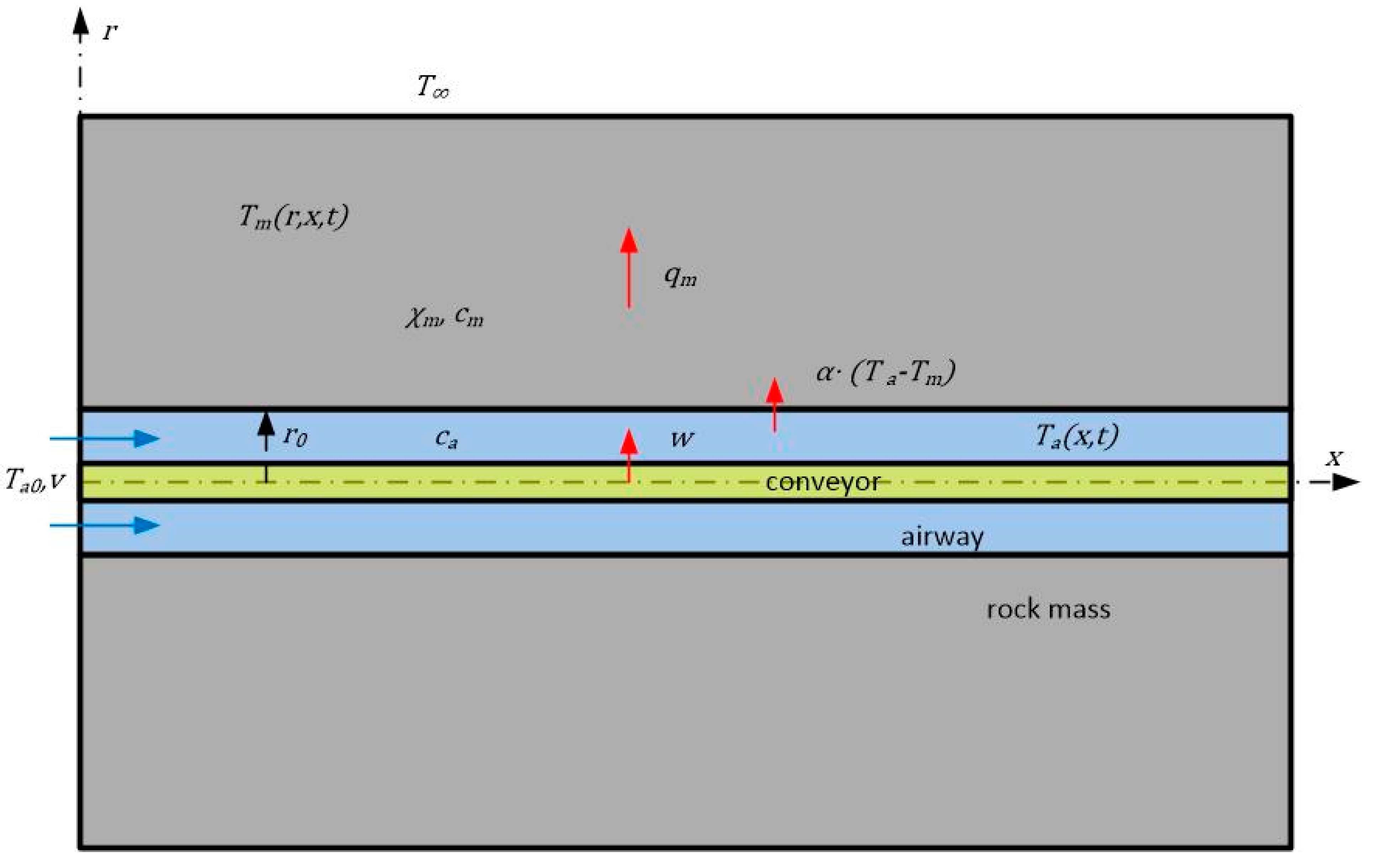
The problem of heat exchange between mine air and rock mass with heat sources distributed along the length of a horizontal conveyor roadway is modeled assuming cylindrical symmetry of the roadway with two spatial coordinates—radial (m) and horizontal (m) [6]. The values of volumetric heat capacity (J/(m3·°C)) and thermal diffusivity (m2/s) of a rock mass are considered constant. Air with volumetric heat capacity (J/(m3·°C)) and constant temperature (°C) is supplied to the entry of the roadway (x = 0) with radius (m). Assuming insignificant changes in air density (kg/m3) and velocity (m/s), these values are assumed to be constant and correspond to the average air density. It is assumed that at the initial moment of time before the heat source is turned on, the entire rock mass and all the air in the excavation at x > 0 have the temperature of the “undisturbed” rock mass (°C). Because the turbulent thermal conductivity of air is much greater than the molecular thermal conductivity of rock, it can be assumed that the air temperature along the excavation cross section equalizes instantly. Meanwhile, the diffusive heat transfer in the air movement direction is insignificant compared to convective heat transfer; therefore, the longitudinal thermal conductivity in air can be set to zero—i.e., heat transfer along the excavation is only convective air movement. A similar simplification is made since the air velocity is much higher than the intensity of heat propagation in the rock mass; i.e., temperature differences along the x axis and in the radial direction in the rock mass will be of different orders: in , meters, in , centimeters. This makes it possible to neglect the propagation of heat in the direction of the x axis in the rock mass. Thus, only radial thermal conductivity takes place in both the rock mass and air, while the longitudinal thermal conductivity is considered insignificant and is not considered in the model. Another important characteristic of the air flow is its relative humidity. However, in this study, we did not analyze its distribution for two reasons—due to the absence of significant sources of moisture in the potash mine, and also due to the fact that the regulatory requirements place restrictions only on the dry bulb temperature.
The computational scheme for the problem is shown in Figure 2.
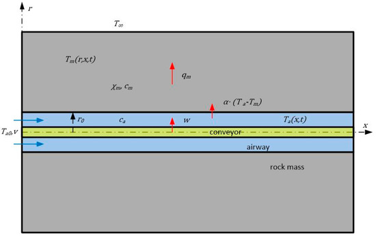
Figure 2.
Computational scheme.
To simplify the mathematical notation of the problem, dimensionless coordinates are introduced:
Air temperature (°C) and rock mass temperature (°C) are counted from the value . These parameters remain dimensional.
Dimensionless variables are written with a prime. The equation of heat conduction in the rock mass in cylindrical coordinates has the following form:
The density of the heat flux from the air to the rock mass (J/(m2·s)) should be equal to the density of the heat flux (J/(m2·s)) incoming through the excavation wall = 1 to the rock mass. It is necessary to write an equation for the balance of heat (J) in an elementary volume of air (m3) with a cross-section area (m2) and thickness (m) with the heat exchange surface of volume (m2).
Since the thermal conductivity of air in the radial direction in the model is assumed to be infinite, the heat balance is reduced to the equality of the total heat flux through and the change in heat content in a volume of air (in dimensional form):
where is the volume source of heat, J/(m3·s).
Equation (2) differs from the model presented in [8] by the presence of an additional term , which specifies the intensity of heat release from a source (conveyor belt) uniformly distributed along the length of the excavation. A similar approach to heat transfer modeling was used in [9] to describe air heating due to its hydrostatic compression while moving along an air supply shaft.
The problem is solved analytically to obtain a definite integral, for the calculation of which the numerical method of trapezoids is used; the solution is implemented in a self-written program in the Pascal language.
This makes it possible to obtain an exact solution of the heat transfer problem without introducing restrictions on the computational area of the array and to use the most physical boundary condition at an infinite radius value. In addition, the proposed solution allows one to quickly calculate the air temperature even at long heat transfer times.
Note that
The condition at the boundary of the air with the rock mass in dimensionless form takes the following form:
The second boundary condition contains information about the value of the heat transfer coefficient and determines the temperature difference between the air and the rock mass at the boundary (excavation wall):
Since condition (3) contains a derivative concerning the coordinate, it must be supplemented with the value (°C) of the air temperature at the beginning of the excavation; thus,
The whole system of equations is supplemented with the initial condition for temperature fields:
The unsteady cylindrical problem (1)–(6) is solved using the Laplace transformation [20]. The functions of air and rock mass temperatures are associated with their images.
Here, is a complex parameter with domain .
The partial differential Equation (1) for the original is reduced to an ordinary differential equation for the image :
with the following boundary and initial conditions:
which are obtained from conditions (3)–(5), respectively.
Equation (7) is the Bessel equation, the solution of which is
where and are the zero-order Bessel and Neumann functions, and the coefficients and are to be determined [21]. The connection between them sets the condition at infinity:
The ratio between the coefficients and should be such that when and ,
Based on the asymptotic expansions of the functions and as [9], we can conclude that in (12), for and for . The function , where is a complex number, is two-valued, and only one of its values should appear in the calculation. This value can be specified by the condition . After representing in exponential form , it is easy to verify that the condition corresponds to the condition and vice versa; the condition corresponds to the condition .
Laplace transforms allow one to separate the variables and and reduce the dimension of the problem. Now, taking = 1, only the dependence on remains and, after a transition to the original, on . Further, the coordinate is omitted, which means = 1. After substituting (11) into (9), the coefficient , taking into account (7), is expressed in terms of :
Now, after substituting (13) into (11) and (11) into (8), we obtain a differential equation with one unknown function, :
Solution (14), taking into account (10), gives the dependence
which coincides with the formula obtained in [8] for heat transfer without heat release sources. Restoring the original,
where the integration is carried out along any straight line with a real coordinate greater than the growth rate of the function .
To determine the heat transfer coefficient, which determines the parameters and , the dependence [6] can be used:
This dependence was obtained for cylindrical channels with airflow at Reynolds numbers over 104.
The obtained Formulas (15) and (16) make it possible to calculate the air temperature as a function of time and longitudinal coordinates. The numerical integration of expression (16) was done using the trapezoidal rule.
4. Results and Discussion
In accordance with the developed mathematical model of heat transfer in an excavation with distributed heat sources, a numerical assessment was made of air heating by a moving conveyor belt after a long period (after 1 year) of usage. The purpose of the calculation was also to optimize the distribution of the given airflow in two parallel air supply excavations (the conveyor and haulage roadways) according to the criteria for minimizing the air temperature of the mixed air streams at the outlet. An additional limitation was not exceeding the maximum allowable air temperature in the conveyor roadway. The calculation parameters in dimensional form were as follows. The cross-section area of two parallel excavations was assumed to be 11 m2, and the length was 3000 m. The total air flow rate along two excavations was 10 m3/s. The average intensity of heat release in the conveyor roadway was 100 W/m, taking into account the cyclic operation of the conveyor and the fact that the conveyor operates only 50% of the total shift time. The temperature of the rock mass was +21 °C, and the initial temperature of the air entering the excavations was +18 °C. The thermal conductivity of the rock mass was 5 × 10⁻⁶ m2/s, and the specific heat capacity of the rock mass was 838 J/(kg∙°C). The density of the rock mass was 2.1 kg/m3. The equivalent diameter of the mine excavation was 3.7 m. In addition, when solving the problem, there was an additional limitation—the air temperature in the conveyor roadway should not exceed +40 °C. Safety rules restrict people from staying in the mine at temperatures >26 °C but still make it possible to operate the electrical conveyor equipment. However, at temperatures >+40 °C, electrical equipment must be turned off.
Table 2 shows the results of calculating the final air temperature after mixing the airflows from haulage and conveyor roadways and the temperature at the end of the conveyor roadway.

Table 2.
Air temperatures at the end of the conveyor roadway and mixed airflow after entering the longwall working area.
The calculated data presented in Table 1 show that the optimal ratio of air distribution along the roadways under the given conditions is 20% (2 m3/s) in the conveyor roadway and 80% (8 m3/s) in the haulage roadway. At the same time, the minimum temperature of the mixed air is +22 °C, and the temperature in the conveyor drift does not exceed +40 °C (the limiting temperature of the electrical equipment).
It should be noted that the heat exchange time (1 year) from the beginning of the conveyor operation is not large in the sense of reaching the maximum possible temperature (°C) at the outlet of the conveyor roadway, which, after an infinitely long time, should correspond to the adiabatic solution:
where is the air flow rate, m3/s.
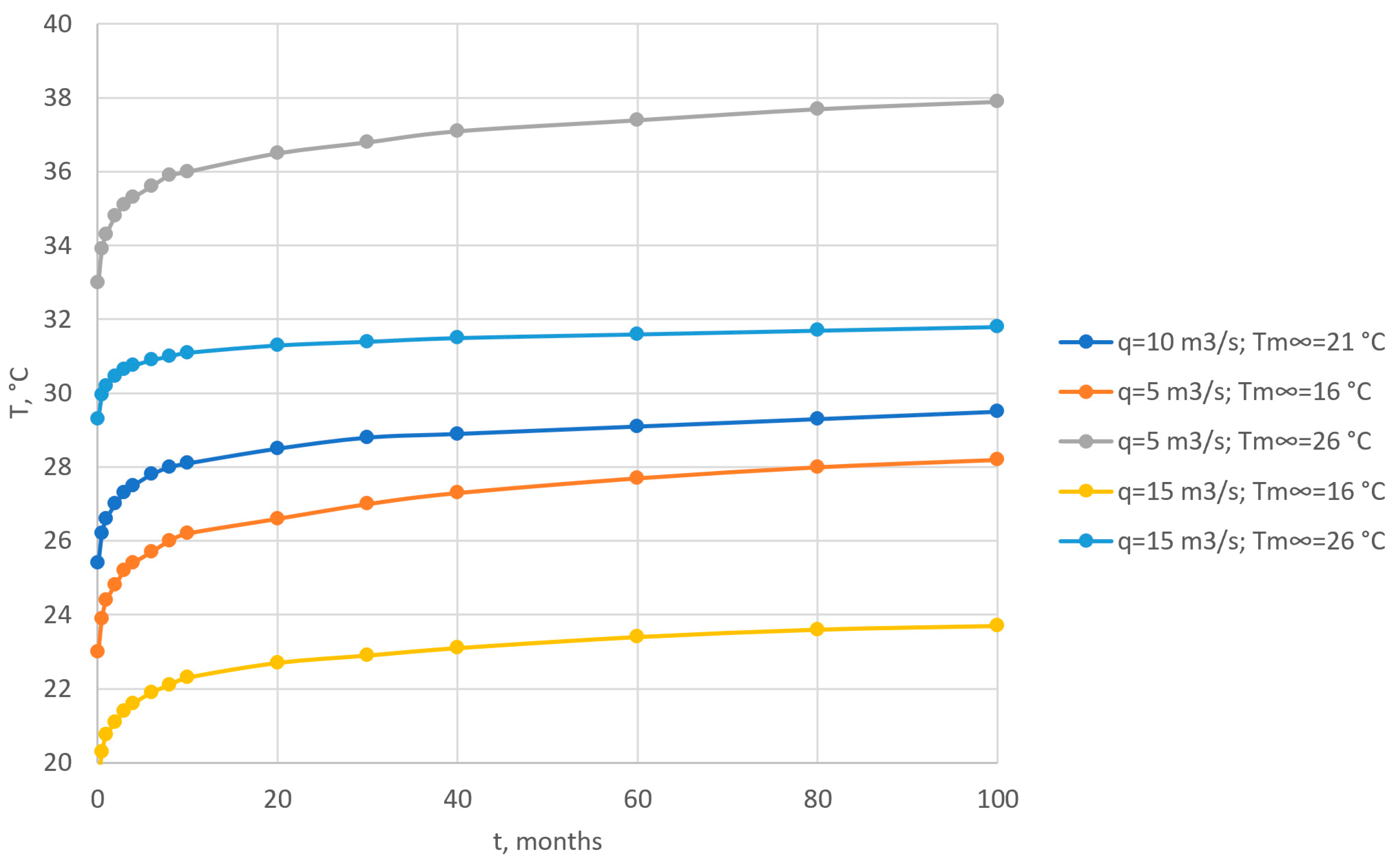
With the given parameters of the problem, when all the air goes along the conveyor roadway, its outlet temperature tends to +43 °C. This value is much higher than the outlet air temperature of +28.2 °C obtained in the calculation. Thus, the temperature in the excavation will continue to increase; however, the rate of increase will decrease yearly, as shown in Figure 3. This is true for various ventilation parameters (q) and thermal conditions ().
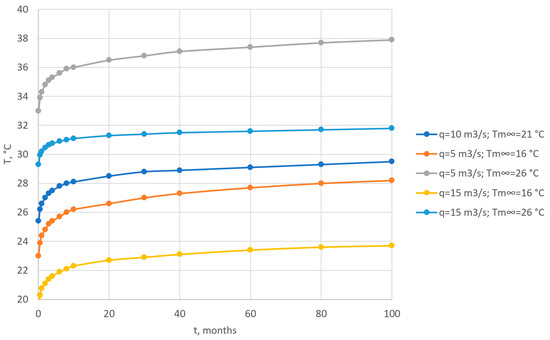
Figure 3.
Air temperature at the end of the conveyor roadway vs. time.
Judging by the calculated data, even after 100 months from the beginning of mining operations in the longwall and the beginning of heat exchange, the air temperature at the end of the conveyor belt will not exceed 30 °C, which leads to the conclusion that in real-time intervals the heat exchange process is unsteady, the temperature increases at a decreasing rate, and the asymptotic solution will never be reached. In the first month from the beginning of heat exchange, the air temperature at the outlet of the conveyor drift is 27 °C; by the end of the year, it increases to 28 °C; after 4 years, up to 29 °C; after 8 years, it increases by another 0.5 °C, etc.
5. Conclusions
When fresh air is supplied through extended excavations equipped with conveyor systems, the resulting air temperature is determined by the temperature of the surrounding rock mass, total distributed heat from the operating conveyors, total airflow, and total ventilation time.
The generated distribution of air temperatures is sufficiently unsteady. Its asymptotic value at very long times depends on the total heat release and the total supplied airflow. However, this asymptote is not achieved under realistic periods of longwall exploitation.
When air is supplied through two or more excavations—only one of which is equipped with a conveyor—the minimum air temperature of the mixture entering the longwall working zone is ensured by the minimum possible air supply along the conveyor roadway. This leads to maximum air temperatures and a maximum temperature difference between the air and rock mass.
Author Contributions
Conceptualization, A.Z.; methodology, A.Z.; software, A.S.; validation, A.Z., D.B. and A.S.; formal analysis, A.S.; investigation, A.S. and D.B.; resources, D.B.; data curation, A.Z.; writing—original draft preparation, A.Z.; writing—review and editing, A.S. and D.B.; visualization, A.Z.; supervision, A.Z.; project administration, A.Z.; funding acquisition, A.Z., A.S. and D.B. All authors have read and agreed to the published version of the manuscript.
Funding
This research was funded by the Ministry of Science and Higher Education of the Russian Federation, grant number 122030100425-6.
Data Availability Statement
Not applicable.
Conflicts of Interest
The authors declare no conflict of interest.
References
- Kremnyov, O.A. Non-stationary thermal conductivity of hollow solids bounded by a circular cylindrical surface for a given law of its heat exchange with a cooling or heating medium. Rep. Acad. Sci. Sov. Union 1952, 85, 1009–1012. [Google Scholar]
- Levin, L.Y.; Semin, M.A.; Zaitsev, A.V. Mathematical methods of forecasting microclimate conditions in an arbitrary layout network of underground excavations. J. Min. Sci. 2014, 50, 371–378. [Google Scholar] [CrossRef]
- Kremnyov, O.A. Heat exchange between the ventilation jet and the mountain ranges of old mines and workings. Work. Inst. Therm. Power Eng. Acad. Sci. Ukr. Sov. Social. Repub. 1954, 10, 12–17. (In Russian) [Google Scholar]
- Perestoronin, M.P.; Zaitsev, A.V.; Semin, M.A.; Borodavkin, D.A. Experimental study of transient thermal conditions in longwall faces. Gorn. Nauk. I Tekhnologii Min. Sci. Technol. 2022, 7, 37–48. [Google Scholar] [CrossRef]
- Shherban, A.N.; Kremnyov, O.A. Scientific Basis for Calculating and Regulating the Thermal Regime of Deep Mines, 1st ed.; Publishing House of the Academy of Sciences of the USSR: Kiev, Russia, 1959; Volume 1. [Google Scholar]
- Voropaev, A.F. Theory of Heat Exchange between Mine Air and Rocks in Deep Mines, 1st ed.; Nedra: Moscow, Russia, 1966. [Google Scholar]
- Kozdoba, L.A. Computational Thermophysics, 1st ed.; Naukova Dumka: Kiev, Ucraine, 1992. [Google Scholar]
- Krasnoshtein, A.E.; Kazakov, B.P.; Shalimov, A.V. Modeling phenomena of non-stationary heat exchange between mine air and a rock mass. J. Min. Sci. 2007, 43, 522–529. [Google Scholar] [CrossRef]
- Kazakov, B.P.; Levin, L.Y.; Shalimov, A.V.; Zaitsev, A.V. Development of energy-saving technologies providing comfortable microclimate conditions for mining. J. Min. Inst. 2017, 223, 116–124. [Google Scholar]
- Shalimov, A.V. Theoretical Foundations of Forecasting, Prevention and Control of Emergency Violations of Mine Ventilation. Ph.D. Thesis, Aarhus University, Aarhus, Denmark, 2012. [Google Scholar]
- Semin, M.; Zaitsev, A. On a possible mechanism for the water build-up formation in mine ventilation shafts. Therm. Sci. Eng. Prog. 2020, 20, 100760. [Google Scholar] [CrossRef]
- McPherson, M.J. Subsurface Ventilation and Environmental Engineering, 2nd ed.; Chapman & Hall: London, UK, 2009. [Google Scholar]
- McPherson, M.J. The analysis and simulation of heat flow into underground airways. Int. J. Min. Geol. Eng. 1986, 4, 165–195. [Google Scholar] [CrossRef]
- Roy, T.R.; Singh, B. Computer simulation of transient climatic conditions in underground airways. Min. Sci. Technol. 1991, 13, 395–402. [Google Scholar] [CrossRef]
- Bluhm, S.J.; Von Glehn, F.H.; Marx, W.M.; Biffi, M. VUMA mine ventilation software. J. Mine Vent. Soc. S. Afr. 2001, 54, 65–72. [Google Scholar]
- Lowndes, I.S.; Crossley, A.J.; Yang, Z.-Y. The ventilation and climate modelling of rapid development tunnel drivages. Tunn. Undergr. Space Technol. 2004, 19, 139–150. [Google Scholar] [CrossRef]
- Zaitsev, A.V.; Semin, M.A.; Parshakov, O.S. Features of the thermal regime formation in the downcast shafts in the cold period of the year. J. Min. Inst. 2021, 250, 562–568. [Google Scholar] [CrossRef]
- Zhu, S.; Cheng, J.; Wang, Z.; Borowski, M. Physical simulation experiment of factors affecting temperature field of heat adjustment circle in rock surrounding mine roadway. Energy Sources Part A Recovery Util. Environ. Eff. 2020, 1–18. [Google Scholar] [CrossRef]
- Zhang, S.; Lu, P.; Wang, H. Numerical simulation analysis of unsteady temperature in thermal insulation supporting roadway. Math. Probl. Eng. 2019, 2019, 6279164. [Google Scholar] [CrossRef]
- Sobolev, S.L. Equations of Mathematical Physics, 1st ed.; State Publishing House of Technical and Theoretical Literature: Moscow, Russia, 1950. [Google Scholar]
- Dvajt, G.B. Integral Tables and other Mathematical Formulas, 1st ed.; Nauka: Moscow, Russia, 1973. [Google Scholar]
Disclaimer/Publisher’s Note: The statements, opinions and data contained in all publications are solely those of the individual author(s) and contributor(s) and not of MDPI and/or the editor(s). MDPI and/or the editor(s) disclaim responsibility for any injury to people or property resulting from any ideas, methods, instructions or products referred to in the content. |
© 2023 by the authors. Licensee MDPI, Basel, Switzerland. This article is an open access article distributed under the terms and conditions of the Creative Commons Attribution (CC BY) license (https://creativecommons.org/licenses/by/4.0/).

