Article

A Computational Fluid Dynamics Study to Compare Two Types of Arterial Cannulae for Cardiopulmonary Bypass

1
Department of Medical and Surgical Sciences, University “Magna Graecia”, Viale Europa, 88100 Catanzaro, Italy
2
Cardiac Surgery Department, Grande Ospedale Metropolitano “Bianchi-Melacrino-Morelli”, 89133 Reggio Calabria, Italy
*
Author to whom correspondence should be addressed.
These authors contributed equally to this work.
Fluids 2023, 8(11), 302; https://doi.org/10.3390/fluids8110302
Submission received: 25 September 2023 / Revised: 24 October 2023 / Accepted: 10 November 2023 / Published: 16 November 2023
(This article belongs to the Special Issue Advances in Hemodynamics and Related Biological Flows)

Abstract

:
Thanks to recent technological and IT advances, there have been rapid developments in biomedical and health research applications of computational fluid dynamics. This is a methodology of computer-based simulation that uses numerical solutions of the governing equations to simulate real fluid flows. The aim of this study is to investigate, using a patient-specific computational fluid dynamics analysis, the hemodynamic behavior of two arterial cannulae, with two different geometries, used in clinical practice during cardiopulmonary bypass. A realistic 3D model of the aorta is extracted from a subject’s CT images using segmentation and reverse engineering techniques. The two cannulae, with similar geometry except for the distal end (straight or curved tip), are modeled and inserted at the specific position in the ascending aorta. The assumption of equal boundary conditions is adopted for the two simulations in order to analyze only the effects of a cannula’s geometry on hemodynamic behavior. Simulation results showed a greater percentage of the total output directed towards the supra-aortic vessels with the curved tip cannula (66% vs. 54%), demonstrating that the different cannula tips geometry produces specific advantages during cardiopulmonary bypass. Indeed, the straight one seems to generate a steadier flow pattern with good recirculation in the ascending aorta.

1. Introduction

Numerical methods and analytic solutions have grown rapidly over the last few decades, with applications in physics, engineering, biology, and finance, among others [1,2,3]. Mathematical modeling of the cardiovascular system has received considerable attention in the literature and is poised to become one of the heavy challenges of the coming decades due to its potential applications in the prediction of pathologies and in the planning of surgical therapies. Computational fluid dynamics (CFD) is classified as a branch of fluid dynamics that uses numerical solutions of the governing equations to simulate real fluid flows [4].
The emphasis in using the CFD approach lies in the possibility, by means of a computer-based simulation, to understand the physiological blood flow behavior in the cardiovascular system, evaluate the effects that vascular modifications or inlet of different pathologies can have on local hemodynamics, facilitate surgical planning, and develop medical devices that are otherwise hard to test in vivo [4].
This mathematical simulation platform can thus provide cardiologists with the support tools for clinical practice, able to analyze the behavior of the cardiovascular system under physiological conditions, predict the onset of particular diseases or disorders, and anticipate the effects of surgical or pharmacological changes.
Recently, CFD has been applied in the context of medical bioengineering [5] and cardiovascular diseases [6,7,8]. Most of the studies on CFD are used to investigate the flow patterns in anatomical vessels and to quantify the relationship between hemodynamic factors and atherosclerosis [9,10]. Other applications include guiding new product development and predicting device performance in situ. Blood pumps, artificial heart valves, blood oxygenators, filtration devices, catheters, tubing, and diagnostic equipment [11,12,13] can be considered the most widespread examples.
Several contributions described the CFD analysis to investigate the flow pattern induced by the aortic cannula during CPB [14,15,16,17] or in the presence of aortic pathologies [18,19]. Over recent years, the development and improvement of the aortic cannulation procedure has been the subject of enormous interest. During open-heart surgery, the aortic cannula was inserted, as a surgical equipment, into the ascending aorta in conjunction with the heart-lung machine which is used to drain the blood away from the heart [20]. Establishing an adequate arterial cannulation is a very important event in the cardiopulmonary bypass procedure. Indeed, arterial cannulation maintains a normal circulatory flow of the blood within the body and, if not handled correctly, it may result in many possible complications.
In Gramigna et al. [14], the hemodynamics in the ascending aorta and in the supra-aortic vessels between non-pulsatile traditional cardiopulmonary bypass and pulsatile CPB were analyzed by means of CFD. This CFD analysis used a multi-scale model of a 3D patient-specific aorta geometry, the arterial cannula of the CPB, and the intra-aortic balloon (IAB), with a 0-dimensional model. Deng et al. [15] used a numerical model based on computational fluid dynamics to analyze the difference of several cannulation methods on the blood flow property in a type A aortic dissection (TAAD) model. Hungeroth et al. [16] dealt with an outflow-optimized cannula design (optiCAN), which was improved using computational fluid dynamics models, prototyped, and tested in vitro as well as in vivo. In Caruso et al. [17], a comparative multi-scale study was performed, by coupling three-dimensional computational fluid dynamics and a 0D model in order to establish the modifications of blood flow caused by the changes in the cannula insertion angle during a cardiopulmonary bypass. More specifically, in this preliminary CFD study [17], we numerically analyzed how the CPB cannula orientation influences the blood flow in aortic and epiaortic vessels during pulsed CPB. We investigated the hemodynamic modifications (flow distribution, velocity pattern, and stressed areas), considering a CPB arterial cannula with two different tilt angles, which were chosen as the extremes of the range within which the cannula orientation can vary without causing any problems to the surgical field. Malvindi et al. [18] performed a pre-dissection computational fluid analysis of an ascending aortic aneurysm associated with the unicuspid aortic valve. In Xu et al. [19], in a longitudinal study performed for a type B aortic dissection (TBAD) patient, CFD simulations were used to compute several hemodynamic indexes, including the wall shear stress and the relative residence time (RRT).
The aim of this study is to analyze the hemodynamic behavior of two arterial cannulae. We considered two different cannula geometries used in clinical practice during a cardio-pulmonary bypass. The analysis was performed by using a fluid dynamics study on a patient-specific geometry. Compared to our previous analysis [17], in this study, a more complete aorta model was used in addition to modeling outlets in the thoracic area, which could influence the results.

2. Materials and Methods

2.1. Anatomical Model

A real (3D) patient-specific geometry model of the aorta artery was realized from a series of medical images by using open-source software. More specifically, we used DICOM (Digital Imaging and Communications in Medicine) images from an in vivo contrast-enhanced axial computed tomography. Scan slices were conducted for diagnostic purposes. The derived faced surface was simplified for the CFD analysis using a reverse engineering method, as described in our previous study [14]. The aorta model was designed including the upper ramifications (innominate artery, left carotid artery, and left subclavian artery). Two 22 Fr (7.3 mm diameter) arterial cannulae (Select Series™ Straight and Angled Tip Arterial Cannulae, Medtronic Inc., Minneapolis, MN, USA [Medtronic cannula catalog 2020]) with similar geometry except for the distal end (straight or curved tip), that are routinely used during a cardiopulmonary bypass, were modeled (Figure 1). They were inserted into the ascending part of a patient-specific aorta, 2 cm above the ST junction perpendicular to the aortic wall (Figure 2). This position provides the best hemodynamic pattern as has been indicated in our previous research [21]. The two cannulae with different types of distal ends (Case I: straight or Case II: curved tip) were used to evaluate the influence of tip curvature on fluid dynamics within the aortic model.

2.2. Mathematical Model, Boundary Conditions, and Simulation Details

The 3D incompressible Navier–Stokes equations were considered to model the blood motion:
∇∙u = 0
ρ (∂u/∂t) + ρ (u∙∇)u = ∇∙[−pI + μ (∇u + (∇u)T] + F
where u is the fluid velocity vector, ∇u is the tensor derivative of the velocity vector u, p is the pressure, μ is the dynamic viscosity, ρ is the density of blood, I is the identity matrix, and F is the volume force field.
It is important to specify that, since the patient was supine during the surgical procedure, the term F was neglected in the computational study (the effect of gravity was ignored).
Thus, to describe the blood motion, the following equation is considered:
ρ (∂u/∂t) + ρ (u∙∇)u = ∇∙[−pI + μ (∇u + (∇u)T]
We considered blood using Newtonian flow, an accepted assumption for flows in vessels as large as the aorta [22]. Blood density ρ and dynamic viscosity μ were assumed to be equal to 1060 kg/m3 and 0.0035 Pa s, respectively.
In most previous CFD studies, for simplicity, blood was simulated as a Newtonian fluid despite the fact that blood does not have a Newtonian behavior. As the flow velocity and shear strain rate increase, the viscosity of the blood decreases [23,24]. However, in areas with low flow, the viscosity is greater than that considered, and non-Newtonian models could simulate changes in the blood viscosity in these areas. Previous studies simulated the blood flow in various vessels and indicated differences in pressure and wall shear stress (WSS) estimates based on Newtonian and non-Newtonian models [25,26,27]. We carried out a study on a large vessel and, for these reasons, we approximated the blood as a Newtonian fluid.
For both cases, we hypothesized that the blood was delivered only through the arterial cannula, and the aorta was modeled with a closed input (no flow came out from the aortic valve). More specifically, a constant flow of 5.00 L/min was assumed as the inlet boundary condition required to flow through the CPB arterial cannula. The zero-pressure outlet boundary conditions were assumed at the exits of the aorta artery (innominate artery, left carotid artery, left subclavian artery, and thoracic aorta).
Since the aim of our study was to analyze only the effects of a cannula’s geometry on hemodynamics, the assumption of identical boundary conditions for both simulations was chosen.
The blood flow motion was described by adopting the laminar model. Indeed, with a flow of about 5 L/min, the Reynolds number was about 3800 in the arterial cannula and about 1100 in the ascending aorta. Turbulent flow was not considered since the Reynolds number is only in the cannula in the transient range and the analysis of flow in this conduit was not of interest.
In this study, COMSOL 6.1 (COMSOL Inc., Stockholm, Sweden), a finite element analysis solver for various physics and engineering applications [28], was used.
For the computational fluid dynamics simulation, the aorta and the CPB cannula walls were assumed to be inflexible and no-slip boundary conditions were assumed. Furthermore, to evaluate the hemodynamic in the aorta vessel, two steady-state simulations were performed:
(a)
Case I: Straight Tip Arterial Cannula;
(b)
Case II: Angled Tip Arterial Cannula.
To analyze the mesh quality and performance, several measures can be calculated using COMSOL 6.1 (http://www.comsol.com, accessed on 24 September 2023), such as the minimum element quality, element volume ratio, and maximum growth rate. For both cases (I and II), the optimal mesh parameters were chosen in order to obtain good quality, acceptable calculation times, and accurate solutions. The convergence error is in the order of 10−6.
More specifically, the meshes included two boundary layers and tetrahedral elements (113,489 elements for case I and 113,049 elements for case II), both with a minimum element quality of 0.007115, an average element quality of 0. 7, and an element volume ratio of 1.7 × 10⁻⁶ (Figure 3). On the one hand, it is true that results are more accurate when the refinement increases. On the other hand, it is equally true that the calculation burden, and, consequently, computational times are significantly affected from mesh quality. It is therefore necessary to define a sufficiently fine step beyond which, even with further refinement, no improvements are obtained. In the case taken into consideration, lower computational times were preferred, since an extremely refined solution is not of interest. To solve the Navier–Stokes equations, these further choices have been made: the Pardiso solver with a pivoting perturbation of 1.0 × 10⁻¹³, the P1–P1 finite element method for the space discretization, linear elements for both the velocity components, and the pressure field. An Intel Xeon 2.10 GHz with 192 GB RAM was used.
In addition to the flow distribution and velocity pattern, to evaluate the impact of the two types of cannula distal ends on flow perfusion, the wall shear stress (WSS) [19], expressed in Pascals (Pa), was also considered. WSS describes the friction force exerted by blood motion on the vessel surface in a direction on the local tangent plane, which affects endothelial cell function and can cause different vascular pathologies, such as atherosclerosis, thrombosis, aneurysms, and stenosis [29]:
W S S = ( ( τ x ) 2 + ( τ y ) 2 + ( τ z ) 2 )
where τ x , τ y , and τ z are the viscous stress in x, y, and z directions, respectively.

3. Results

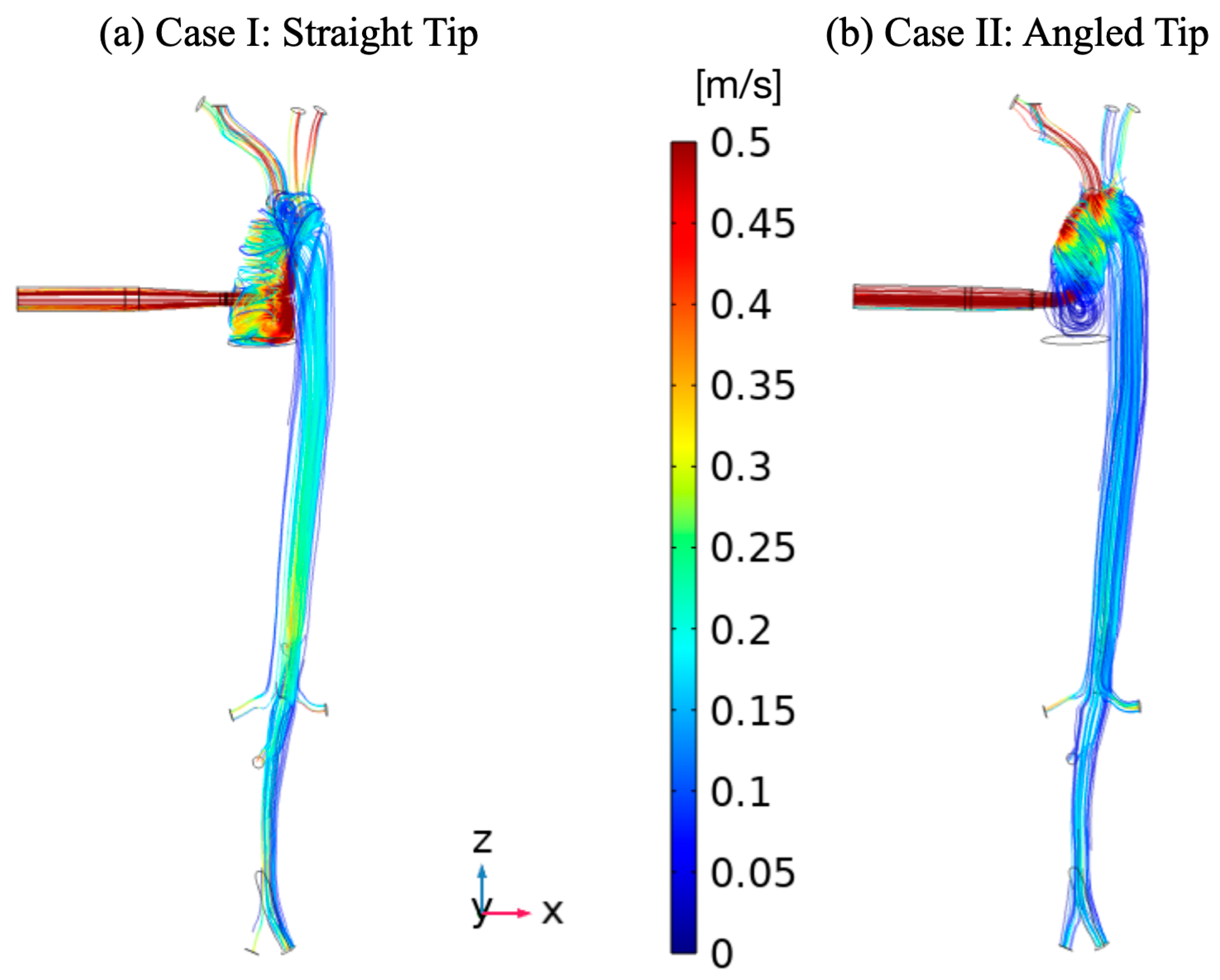
The flow distribution in terms of the streamline in all vessels and in the aortic CPB cannula for the two analyzed cases are shown in Figure 4.
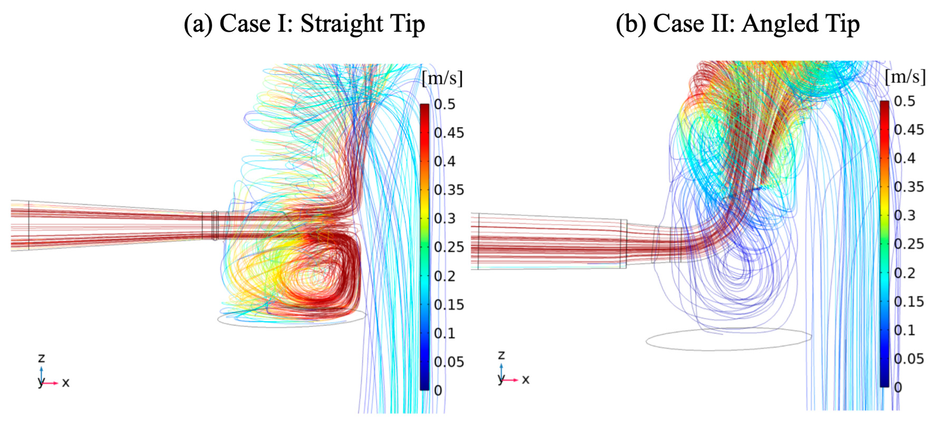
A zoomed view of the cannula insertion area on the ascending aorta is shown in Figure 5.
Figure 4 and Figure 5 show that the straight tip cannula produced an important flow that hit the inner wall of the ascending aorta, resulting in more evident flow recirculation in the ascending aorta below the cannulation site and in an orderly flow pattern in the supra-aortic vessels. On the contrary, the angled tip cannula caused a swirling flow with stasis in the ascending aorta below the cannulation site and a predominant flow distribution in the brachiocephalic artery.
Interestingly, a greater percentage of the total output directed towards the supra-aortic vessels with the curved tip cannula (Case II) compared to the straight one (Case I) was observed (66% vs. 54%) (Table 1).
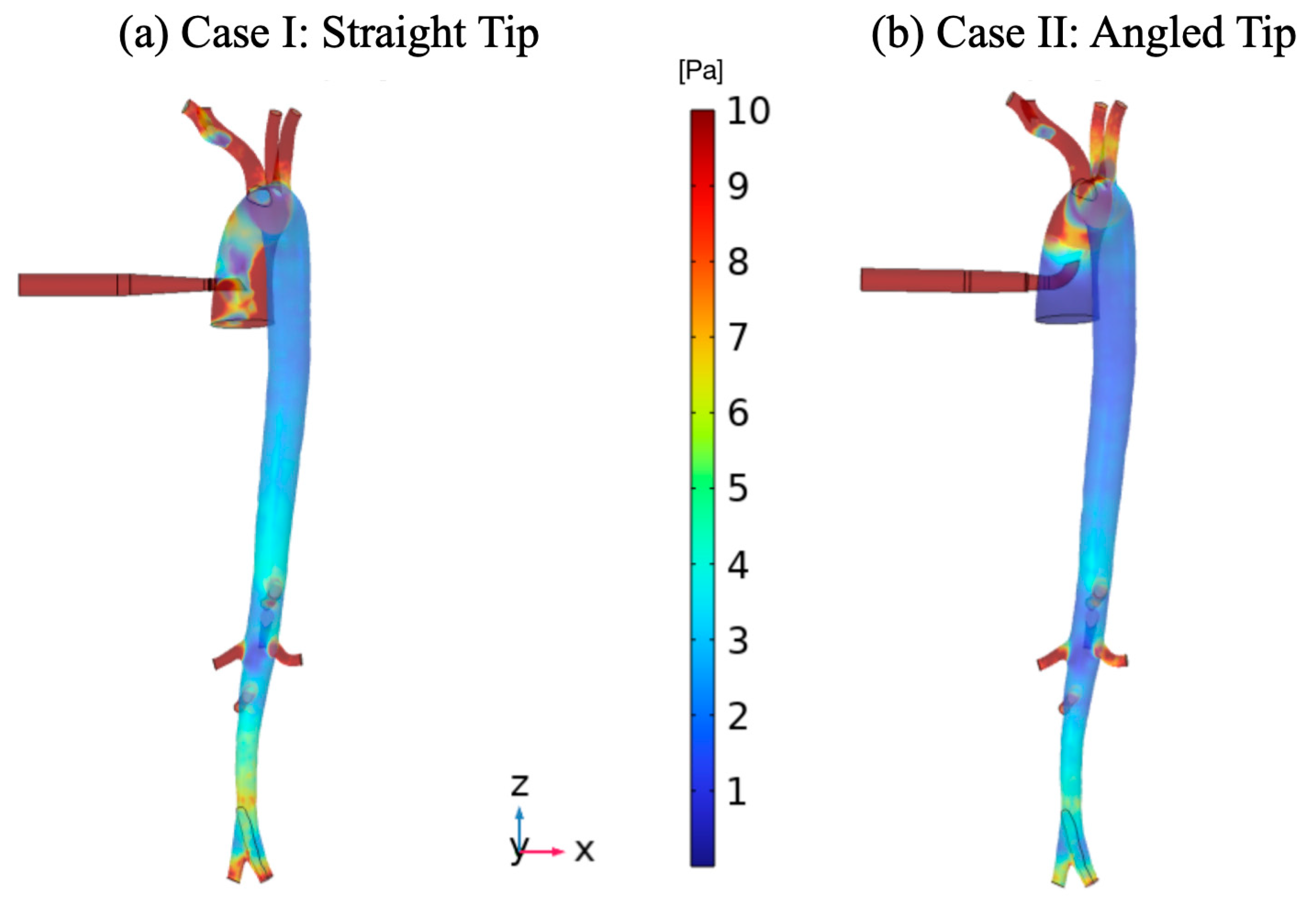
A similar behavior was observed while considering the high wall shear stress (WSS) (Figure 6) for both cases near the take-off of the innominate artery and the right carotid artery. Indeed, a slightly higher value for the curved tip compared to the straight one has been evaluated. In addition, in the straight tip case, it was also located on the posterior wall of the aorta opposite the cannulation area.
In conclusion, this non-invasive evaluation demonstrated that using different cannula tips offers specific advantages during CBP. The straight one seems to generate a more orderly flow pattern in the epiaortic vessels but with a lower percentage of blood flowing through them. On the contrary, the cannula with curved tip, even though it seems potentially more thrombogenic, offers an enhanced blood flow selectively to the epiaortic vessels.

4. Discussion

Mathematical modeling of the cardiovascular system has received considerable attention in the literature. It is poised to become one of the heavy challenges of the coming decades due to its potential applications in the prediction of pathologies and in the planning of surgical therapies. The primary objective of this study was to investigate the hemodynamic behavior of two different arterial cannulae, which are routinely utilized during cardiopulmonary bypass, using a patient-specific geometry. In our first CFD investigation [17], we numerically investigated how the CPB cannula orientation influences the blood flow in aortic and epiaortic vessels during pulsed CPB. More specifically, we evaluated the hemodynamic modifications (hemodynamic, velocity pattern, and stressed areas) considering two CPB arterial cannulae with different tilt angles. This choice was made taking into account the extremes of the range within which the cannula orientation can vary without causing any problems to the surgical field.
Compared to the previous one, in this study, a more complete aorta model was used in addition to also modeling outlets in the thoracic area, which could influence the simulations results. Nowadays, the cannula choice is left to the surgeon’s preference. However, according to the manufacturer, the angled tip cannula offers enhanced flow directed to the supra-aortic vessels, even if in a case of higher flow resistances, the higher cardiac output is in a logarithmic proportion respective to the straight one. Our work showed results in line with manufacturer specifications, confirming that using different cannula tips offers specific advantages during CBP. More specifically, the straight tip cannula produced maximum WSS to the inner wall of the ascending aorta, more evident flow recirculation in the ascending aorta below the cannulation site, and an orderly flow pattern in the supra-aortic vessels. On the contrary, the angled tip cannula caused a swirling flow with stasis in the ascending aorta below the cannulation site and a predominant flow distribution in the brachiocephalic artery with a higher WSS value localized in that area. Our conclusion must be taken in relation with the cardiac output needed during CBP. We tested the two cannulae with a cardiac output of 5 L/min. That is enough to cover most of the patient’s needs during CBP and light hypothermia (34–32 °C) as is routinely utilized in cardiac surgery. It is reasonable that for higher needs, i.e., in patients with BSA > 2.0 m2 (BSA: external surface area of the human body given in square meters.), the flow turbulence and WSS of the angle tip cannulae will become worse and might jeopardize its hemodynamic performance. Therefore, the cannula choice must also be taken with the cardiac output need.
The CFD method described in this study can be seen as a promising tool to integrate the existing knowledge of CBP effects on aortic hemodynamics. On the other hand, it presents several limitations that have been underlined.
The first assumption is the hypothesis of rigid surfaces ignoring wall compliance and applying the no-slip boundary conditions. This hypothesis was made to reduce the simulation time, which was very high when parametric studies were performed, and is useful in obtaining the first results. Indeed, CFD results could be taken into account before performing fluid–structure interaction (FSI) models, which will be considered in a future perspective of this preliminary computational study.
Moreover, we assumed blood is an incompressible fluid, which is an accepted assumption for vessels as large as the aorta [22]. Regarding future research directions, to estimate the transitional flow in the aorta and in its superior vessels, we will intend to use a low Reynolds number model (k-omega).
Another assumption is the adoption of zero-pressure for outlet boundary conditions.
However, even though simplified, the CFD simulation is a valid and innovative tool to assist clinicians during their decision making.

5. Conclusions

In recent years, the development and improvement of the aortic cannulation procedure has been the subject of enormous interest. Establishing an adequate arterial cannulation is a very important event in cardiopulmonary bypass surgical intervention, since it maintains a normal circulatory flow of the blood within the body and, if not handled correctly, it may result in many possible complications. The aim of this work was to evaluate the hemodynamic behavior of two different arterial cannulae, which are routinely used during cardiopulmonary bypass, using a patient-specific computational fluid dynamics model. Although the cannula choice is nowadays left to a surgeon’s preference, the manufacturer certifies that the angled tip cannula offers enhanced flow directed to the supra-aortic vessels compared to the straight one. Our work showed results in line with manufacturer specifications, confirming that using different cannula tips offers specific advantages during CBP.
The simulation analysis showed a greater percentage of the total output directed towards the epiaortic vessels with the curved tip cannula (66% vs. 54%), which highlights that the different cannula tip geometry produces specific advantages during CPB. Indeed, the straight cannula seems to generate a steadier flow pattern, which also avoids the stagnation phenomena in the ascending aorta.
The aim of this study is to set up a mathematical simulation platform to provide cardiac surgeons with support tools for their clinical practice. This can be seen as an important tool to analyze the behavior of the cardiovascular system under physiological conditions as well as to predict the onset of particular diseases or disorders and anticipate the effects of surgical or pharmacological changes.

Author Contributions

Conceptualization, G.F., A.P. and V.G.; methodology, G.F., A.P. and V.G.; software, G.F., V.G. and A.P.; validation, M.R. and G.F.; formal analysis, G.F., V.G. and A.P.; investigation, M.R. and G.F.; data curation, M.R., G.F., V.G. and A.P.; writing—original draft preparation, G.F., V.G., A.P. and M.R.; writing—review and editing, G.F., V.G., A.P. and M.R.; visualization, V.G. and A.P.; supervision, G.F. and M.R. All authors have read and agreed to the published version of the manuscript.

Funding

This research received no external funding.

Institutional Review Board Statement

Not applicable.

Informed Consent Statement

Not applicable.

Data Availability Statement

The data presented in this study are available on request from the corresponding author.

Conflicts of Interest

The authors declare no conflict of interest.

References

  1. Zhang, K.; Alshehry, A.S.; Aljahdaly, N.H.; Shah, R.; Shah, N.A.; Ali, M.R. Efficient computational approaches for fractional-order Degasperis-Procesi and Camassa–Holm equations. Results Phys. 2023, 50, 106549. [Google Scholar] [CrossRef]
  2. Yasmin, H.; Aljahdaly, N.H.; Saeed, A.M.; Shah, R. Probing Families of Optical Soliton Solutions in Fractional Perturbed Radhakrishnan–Kundu–Lakshmanan Model with Improved Versions of Extended Direct Algebraic Method. Fractal Fract. 2023, 7, 512. [Google Scholar] [CrossRef]
  3. Yasmin, H.; Aljahdaly, N.H.; Saeed, A.M.; Shah, R. Investigating Families of Soliton Solutions for the Complex Structured Coupled Fractional Biswas–Arshed Model in Birefringent Fibers Using a Novel Analytical Technique. Fractal Fract. 2023, 7, 491. [Google Scholar] [CrossRef]
  4. Schwarz, E.L.; Pegolotti, L.; Pfaller, M.R.; Marsden, A.L. Beyond CFD: Emerging methodologies for predictive simulation in cardiovascular health and disease. Biophys. Rev. 2023, 4, 011301. [Google Scholar] [CrossRef]
  5. Basri, E.I.; Basri, A.A.; Riazuddin, V.N.; Shahwir, S.F.; Zuber, M.; Ahmad, K.A. Computational fluid dynamics study in biomedical applications: A review. Int. J. Fluids Heat Transf. 2016, 1, 2–14. [Google Scholar]
  6. Kumar, N.; Ganesha, A.; Girish, H.; Kumar, S.; Shenoy, B.G. Advances in the application of computational fluid dynamics in cardiovascular flow. Cogent Eng. 2023, 10, 2178367. [Google Scholar] [CrossRef]
  7. Costache, V.S.; Yeung, K.K.; Solomon, C.; Popa, R.; Melnic, T.; Sandu, M.; Bucurenciu, C.; Candea, G.; Santa, A.; Costache, A. Aortic Remodeling After Total Endovascular Aortic Repair With Multilayer Stents: Computational Fluid Dynamics Analysis of Aortic Remodeling Over 3 Years of Follow-up. J. Endovasc. Ther. 2018, 25, 760–764. [Google Scholar] [CrossRef]
  8. Candreva, A.; Nisco, G.D.; Rizzini, M.L.; D’Ascenzo, F.; Ferrari, G.M.D.; Gallo, D.; Morbiducci, U.; Chiastra, C. Current and Future Applications of Computational Fluid Dynamics in Coronary Artery Disease. RCM 2022, 23, 377. [Google Scholar] [CrossRef]
  9. Andelovic, K.; Winter, P.; Jakob, P.M.; Bauer, W.R.; Herold, V.; Zernecke, A. Evaluation of plaque characteristics and inflammation using magnetic resonance imaging. Biomedicines 2021, 9, 185. [Google Scholar] [CrossRef]
  10. Chen, Y.; Liu, J.; Li, M. Non-invasive assessment of intracranial wall shear stress using high-resolution magnetic resonance imaging in combination with computational fluid dynamics technique. Fundam. Res. 2021, 2, 329–334. [Google Scholar] [CrossRef]
  11. Le, T.; Borazjani, I.; Sotiropoulos, F. A Computational Fluid Dynamic (CFD) Tool for Optimization and Guided Implantation of Biomedical Devices. J. Med. Devices 2009, 3, 27553. [Google Scholar] [CrossRef]
  12. Sotiropoulos, F. Computational Fluid Dynamics for Medical Device Design and Evaluation: Are We There Yet? Cardiovasc. Eng. Technol. 2012, 3, 137–138. [Google Scholar] [CrossRef]
  13. Han, D.; Leibowitz, J.L.; Han, L.; Wang, S.; He, G.; Griffith, B.P.; Wu, Z.J. Computational fluid dynamics analysis and experimental hemolytic performance of three clinical centrifugal blood pumps: Revolution, Rotaflow and CentriMag. Med. Nov. Technol. Devices 2022, 15, 100153. [Google Scholar] [CrossRef] [PubMed]
  14. Gramigna, V.; Caruso, M.V.; Rossi, M.; Serraino, G.F.; Renzulli, A.; Fragomeni, G. A numerical analysis of the aortic blood flow pattern during pulsed cardiopulmonary bypass. Comput. Methods Biomech. Biomed. Eng. 2015, 18, 1574–1581. [Google Scholar] [CrossRef] [PubMed]
  15. Deng, L.; Qin, H.; Guan, Z.; Mu, Q.; Xia, Q.; Wang, M.; Huang, W.H.; Gu, K. Computational numerical analysis of different cannulation methods during cardiopulmonary bypass of type A aortic dissection model based on computational fluid dynamics. Ann. Transl. Med. 2021, 9, 667. [Google Scholar] [CrossRef]
  16. Hugenroth, K.; Borchardt, R.; Ritter, P.; Groß-Hardt, S.; Meyns, B.; Verbelen, T.; Steinseifer, U.; Kaufmann, T.A.S.; Engelmann, U.M. Optimizing cerebral perfusion and hemodynamics during cardiopulmonary bypass through cannula design combining in silico, in vitro and in vivo input. Sci. Rep. 2021, 11, 16800. [Google Scholar] [CrossRef]
  17. Caruso, M.V.; Gramigna, V.; Serraino, G.F.; Renzulli, A.; Fragomeni, G. Influence of Aortic Outflow Cannula Orientation on Epiaortic Flow Pattern During Pulsed Cardiopulmonary Bypass. J. Med. Biol. Eng. 2015, 35, 455–463. [Google Scholar] [CrossRef]
  18. Malvindi, P.G.; Pasta, S.; Raffa, G.M.; Livesey, S. Computational fluid dynamics of the ascending aorta before the onset of type A aortic dissection. Eur. J. Cardiothorac. Surg. 2017, 51, 597–599. [Google Scholar] [CrossRef]
  19. Xu, H.; Piccinelli, M.; Leshnower, B.G.; Lefieux, A.; Taylor, W.R.; Veneziani, A. Coupled Morphological-Hemodynamic Computational Analysis of Type B Aortic Dissection: A Longitudinal Study. Ann. Biomed. Eng. 2018, 46, 927–939. [Google Scholar] [CrossRef]
  20. Blauth, C.I.; Cosgrove, D.M.; Webb, B.W.; Ratliff, N.B.; Boylan, M.; Piedmonte, M.R.; Lytle, B.W.; Loop, F.D. Atheroembolism from the ascending aorta. An emerging problem in cardiac surgery. J. Thorac. Cardiovasc. Surg. 1992, 103, 1104–1112. [Google Scholar] [CrossRef]
  21. Rossi, M.; Caruso, M.V.; Fragomeni, G.; Serraino, G.F.; Renzulli, A. Comparative study of different left ventricular assist device outflow graft placement on patient haemodynamics. Interact. Cardio Vasc. Thorac. Surg. 2013, 17 (Suppl. S2), S83. [Google Scholar] [CrossRef]
  22. Formaggia, L.; Perktold, K.; Quarteroni, A. Cardiovascular Mathematics: Modeling and Simulation of the Circulatory System; Springer: Milan, Italy, 2009; Volume 1. [Google Scholar]
  23. Moon, J.H.; Kim, D.Y.; Lee, S.H. Spreading and receding characteristics of a non-Newtonian droplet impinging on a heated surface. Exp. Therm. Fluid Sci. 2014, 57, 94–101. [Google Scholar] [CrossRef]
  24. Johnston, B.M.; Johnston, P.R.; Corney, S.; Kilpatrick, D. Non-Newtonian blood flow in human right coronary arteries: Transient simulations. J. Biomech. 2006, 39, 1116–1128. [Google Scholar] [CrossRef] [PubMed]
  25. Hippelheuser, J.E.; Lauric, A.; Cohen, A.D.; Malek, A.M. Realistic non-Newtonian viscosity modelling highlights hemodynamic differences between intracranial aneurysms with and without surface blebs. J. Biomech. 2014, 47, 3695–3703. [Google Scholar] [CrossRef]
  26. Rabby, M.G.; Shupti, S.P.; Molla, M.M. Pulsatile Non-Newtonian Laminar Blood Flows through Arterial Double Stenoses. J. Fluids 2014, 2014, 757902. [Google Scholar] [CrossRef]
  27. Husain, I.; Labropulu, F.; Langdon, C.; Schwark, J. A comparison of Newtonian and non-Newtonian models for pulsatile blood flow simulations. J. Mech. Behav. Mater. 2013, 21, 147–153. [Google Scholar] [CrossRef]
  28. Comsol. COMSOL-Software for Multiphysics Simulation. Available online: https://www.comsol.com/ (accessed on 4 April 2023).
  29. Stalder, A.F.; Russe, M.F.; Frydrychowicz, A.; Bock, J.; Hennig, J.; Markl, M. Quantitative 2D and 3D phase contrast MRI: Optimized analysis of blood flow and vessel wall parameters. Magn. Reson. Med. 2008, 60, 1218–1231. [Google Scholar] [CrossRef]
Figure 1. Real and modeled different arterial cannulae.
Fluids 08 00302 g001
Figure 2. Aortic model and the two different arterial cannulae: (a) straight tip and (b) angled tip.
Fluids 08 00302 g002
Figure 3. Mesh in case I (straight tip (a)) and in case II (angled tip (b)).
Fluids 08 00302 g003
Figure 4. Velocity field (streamlines) (m/s) in cannula and epiaortic vessels in the case of the straight tip (a) and curved tip (b).
Fluids 08 00302 g004
Figure 5. Velocity field (streamlines) (m/s) in cannula and epiaortic vessels in the case of the straight tip (a) and curved tip (b).
Fluids 08 00302 g005
Figure 6. WSS distribution (m/s) in case I (straight tip (a)) and in case II (angled tip (b)).
Fluids 08 00302 g006
Table 1. Comparison of mean flow rates in aortic vessels between case I and case II.
VesselCase I (Straight Tip) Case II (Angled Tip)
Mean Flow (L/min)% Mean FlowMean Flow (L/min)% Mean Flow
Cannula5.001005.00100
Thoracic aorta2.30461.7034
Epiaortic vessels2.70543.3066
Disclaimer/Publisher’s Note: The statements, opinions and data contained in all publications are solely those of the individual author(s) and contributor(s) and not of MDPI and/or the editor(s). MDPI and/or the editor(s) disclaim responsibility for any injury to people or property resulting from any ideas, methods, instructions or products referred to in the content.