Abstract
Several geometrical modifications for passive flow control applied to a railroad tank wagon were investigated for the purpose of assessing the potential for the aerodynamic optimization of freight trains. The modifications were designed in accordance with applicable requirements and regulations. Four different modifications were investigated in the wind tunnel of the TU Berlin with 1:25 scaled wagon models: face radius, side skirts, fairing of the roof platform, and the newly introduced inter-wagon discs. In order to simulate the positions of the tested wagon at the end of a long train, the boundary layer on the train model setup was artificially thickened by spires. The Reynolds number was in the range of 0.4 × . The results of the experiments show that the proposed measures can reduce the aerodynamic drag of the individual wagon by up to 29%, depending on the location in the train consist. It was also shown that by combining different measures, the individual drag reductions add up. The device with the highest drag reduction was found to be the inter-wagon disc. Three different diameters of the inter-wagon disc were investigated. The largest diameter performed best and was less sensitive to the moving direction of the wagon in comparison to the smaller diameters.
Keywords:
aerodynamics; flow control; train; aerodynamic drag; tank wagon; freight train; bluff body; wind tunnel 1. Introduction
The energy consumption of railway freight transportation is directly related to the aerodynamic drag, which increases with the square of the speed, while other resistances such as the rolling resistance are assumed to be constant [1,2,3]. According to Martini [4], the share of aerodynamic drag in the total driving resistance (and thus, in the power required to overcome it) for container freight trains is already around 40% at a speed of 80–100 km/h (Figure 1). Barkan [5] assigns the share of aerodynamics for mixed freight trains in this speed range to more than 50%. Therefore, in the last few years, several studies on flow around inter-modal freight trains and drag reduction have been carried out [6,7,8,9]. Inter-modal freight trains transport different combinations of standard containers and other cargo.
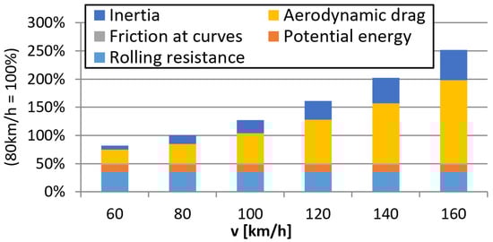
Figure 1.
Specific energy consumption of a container train at different speeds according to [4].
In the present paper, the aerodynamic drag of tank wagons is investigated, and measures for reducing their drag via passive flow control devices are assessed. The results are based on the project “Aufbau und Erprobung von Innovativen Güterwagen” (English: Construction and testing of innovative freight cars) funded by the German Federal Ministry for Digital and Transport (BMDV) in 2016, which was carried out by a consortium consisting of DB Cargo AG and VTG AG [10].
In the following, a brief overview on studies related to the topic is given.
Bendel [11] carried out investigations in 1990, in which a reduction in the face radius of a tank wagon resulted in a drag reduction of about 10%.
Watkins et al. [12] investigated aerodynamic drag reduction for goods trains, using wind tunnel tests with 1:10 scaled models of open top gondola and hopper wagons. Covering the tops—even partially—proved to reduce the drag of unloaded wagons effectively. Reducing the inter-car gap also resulted in drag reduction. In a patent [13], which also addresses the open top hopper wagons, the application of perforated plates to cover the opening are described as drag reducing measures.
Gielow and Furlong [14] studied the influence of the position of a wagon within a train with 30 wagons. Their wind tunnel measurements showed a drag decay when the test car was moved downstream to the eighth position, after which it reached a constant value.
In a numerical study by Maleki et al. [15], the flow topology in the gap between the container freight wagons was analyzed. The authors suggest extenders as means for drag reduction applied to the top and side surfaces of the upstream containers, partially covering the gap. Thereby, the impingement of the separating boundary layer on the downstream container can be avoided, resulting in less drag.
Using Large Eddy simulations, Maleki et al. [16] predicted the drag coefficient of a double-stacked freight train for various loading configurations under yawed wind conditions. It was found that increasing the gap size and yaw angle strongly modifies the mean flow field, and that there is a strong dependence of the drag on the gap length and yaw angle.
The aerodynamic characteristics of containers loaded on an inter-modal freight train was investigated in full-scale field experiments by Quazi et al. [17]. The container was equipped with pressure taps on the front and rear surfaces. Data were acquired over a traveling distance of 700 km and an average speed of 95 km/h. The impact of side wind on the aerodynamic drag was assessed and compared with other data obtained through small scale experiments and numerical simulations.
The literature review shows that studies on drag reduction for freight trains are very scarce. Due to their economical relevance, only inter-modal freight trains loaded with containers have received some attention in recent years.
In the present paper, the following passive flow control measures were investigated as drag reducing modifications for a tank wagon, shown schematically in Figure 2:
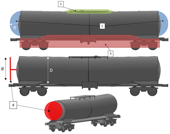
Figure 2.
Modifications applied to the tank wagon. 1: Fairing of platform; 2: face radius; 3: side skirts; 4: inter-wagon disc.
- Fairing of platform;
- Modification of face radius;
- Side skirts;
- Inter-wagon disc.
The selection of these modifications is based on the criteria that the overall geometric contour of the wagon should not be changed too much, and that its operation is not hampered. They will be described in detail in the results sections below. To the knowledge of the authors, no investigations have been carried out on drag reduction for tank wagons using these type of modifications, with the exception of the modification of the front radius by Bendel [11] which was presented in the above review.
2. Experimental Setup
The measurements were carried out in the large wind tunnel of the Hermann-Föttinger Institute of the TU Berlin. The wind tunnel is a closed loop circuit with a small (2 m × 1.4 m × 5 m; W × H × L) high-speed and a large (4.2 m × 4.2 m × 5 m; W × H × L) low-speed measurement section. The current investigations were carried out in the closed high-speed measuring section (Figure 3), in which velocities of up to 68 m/s can be achieved. The test wind speed was m/s, resulting to a Reynolds number of Re = 0.4 × , where with m (divided by the scaling factor of 25), as commonly used in the field of train aerodynamics. In order to keep the boundary layer thickness as small and reproducible as possible, an splitter plate is installed in the test section, which extends over the entire test section length of 5 m. Underneath the test section, an external 6-component force balance is installed for acquiring all forces and moments with a resolution of 0.1 N and 0.3 Nm, respectively. The velocity is measured with a Pitot tube attached to the ceiling of the test section, with an accuracy of m/s. The maximal turbulence level is about 0.5% (measured with hot-wire anemometry). The deviation of the mean velocity within a relevant cross-section of the test section was measured to be less than 2%. The precision error of the drag coefficient measurement was determined to be 1%. For the force measurements, the strain gauge sensors for the 6-component balance were sampled over 30 s at a rate of 2000 Hz.
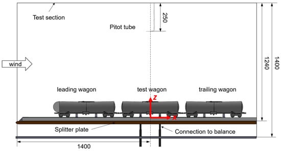
Figure 3.
Train model with tank wagon configuration in the wind tunnel test section and coordinate system (dimensions in mm).
The drag coefficient is defined as
F is the force in the axial direction, is the speed in the wind tunnel, measured above the model to correct for blockage effects, the air density, and A the front area. The value for A is based on 10 m, which is used as a standard value in train aerodynamics divided by the scaling factor of 25.
For the measurement of the aerodynamic drag of a single tank wagon, it is necessary to simulate realistic boundary conditions using a full length train. However, as even the length of a down-scaled train would exceed the available test section length, only a short train configuration, composed of three tank wagons, was used at a scale of 1:25 (Figure 4). The leading wagon was equipped with a rounded nose to avoid excessive flow separation. Only the aerodynamic forces acting on the test wagon were measured and used to compute . For the simulation of the aerodynamic behavior of a long train, nine spires were mounted to the front end of the leading model (Figure 4 left image). This way, the boundary layer thickness of the train was increased to mm. This corresponds to the boundary layer thickness at the end of a 300 m long train, according to [18]. The spires were designed according to Irvin [19].
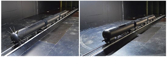
Figure 4.
Model of tank wagon train in test section: (Left): leading wagon with spires, (Right): leading wagon without spires.
A further measure aiming to increase the similarity with realistic boundary conditions is the implementation of a down-scaled ballast and rail model on the splitter plate (Figure 4). Its geometry corresponds to the standard version defined in EN 14067-6, which defines the requirements and test procedures for cross wind assessment for trains and freight wagons. This component increases the vertical distance of the train from the splitter plate by 40 mm, lifting the train out of the boundary layer of the splitter plate, which was measured as 30 mm at . Later measurement campaigns showed that the effect of a ballast and rail setup rather leads to underestimated drag coefficients [18]. However, except for devices in proximity of the ground these effects should not affect the comparability of the current modifications investigated.
The test wagon was connected to the external force balance with two struts (Figure 3). Care was taken to avoid any mechanical contact of the test wagon with the setup, in order not to compromise the force measurement. For this purpose, the wheels of the test wagon were flattened at the bottom so that contact to the rails was avoided.The distance between the flattened part and the top of the rails was adjusted to 2 mm. During the experiments, the struts where shielded with fairings (not shown), so that they were not subjected to aerodynamic forces created from the flow underneath the splitter plate.
3. Results
3.1. Baseline Configuration
In Figure 5, the drag coefficient of the tank wagon in baseline configuration is shown as a function of the Reynolds number. The blue line is obtained without spires, representing a position of the wagon near the head of the train. The orange line is obtained with spires attached to the front dummy wagon, creating a thick boundary layer, and thereby simulating a configuration where the considered tank wagon is located further downstream near the tail of the train. The graph shows that the drag coefficient is , and is a Reynolds number-independent beyond . However, it should be kept in mind that this drag value will probably be slightly larger in reality, as the influence of a moving ground is not simulated in the current setup. Subsequent investigations have shown that the ballast and rail setup tend to have a rather negative effect with regard to a realistic flow simulation when using static ground [18]. Interestingly, the drag of the tank wagon seems rather unaffected by the position in the train, as the comparison of the experiments with and without boundary layer thickening through spires indicates, in Figure 5, for .
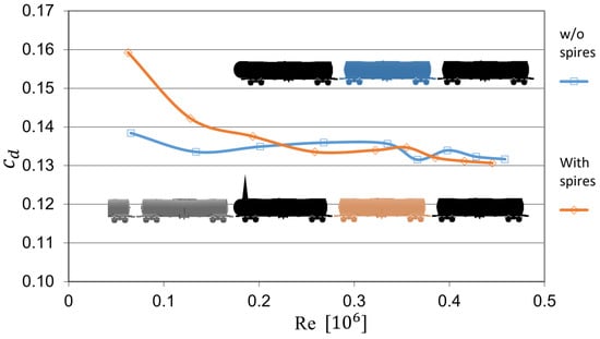
Figure 5.
Baseline drag coefficient of test wagon versus Reynolds number. Blue line: Simulation of tank wagon position near the train head; Orange line: Simulation of tank wagon position near the train end.
3.2. Modification of Face Radius
As a first measure for passive flow control, the modification of the tank wagon’s face radius is presented. This measure affects, on the one hand, the flow in the inter-wagon gap by reducing the available space, and on the other hand, the separation behavior from the tail of the upstream car and reattachment or impingement to the downstream face of the downstream car. A ratio of was selected here, which is quite close to the value investigated by Bendel [11]. The smaller value of of Bendel could not be realized with the existing tank wagon geometry, due to the limited distance between the wagons. Figure 6 shows the change in drag coefficient of the test car with reduced face radius applied either at the front or rear. It can be seen here that apparently different mechanisms are at work. When the wagons are only equipped with a small radius on the upstream faces (case a in Figure 6), the drag is reduced by , while when applying it only to the downstream face, the drag of the test car increases significantly (case b in Figure 6). A similar behavior was observed for a single cylinder in parallel flow [20,21]: the rounding of the downstream face leads probably to an unsteady and undefined separation, which causes the drag to increase. When the small radius is applied simultaneously at the front and rear of the car, much of the gap between the carriages is filled. The drag also increases in this variant (case b in Figure 6), but to a lesser extent than in variant b, so that this cannot be due solely to the positive effect of the upstream rounding. Rather, the closing of the inter-wagon gap will have a favorable effect here, so that the disadvantage of the separation at the downstream face observed in case b is compensated to a certain degree.
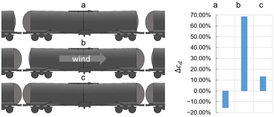
Figure 6.
Influence of face radius; (left) images: a applied to upstream face, b applied to downstream face; c applied to both faces; (right) graph: obtained drag reductions.
It should be noted that the application of the small radius on operating trains would only be practical if it is not dependent on the driving direction of the train. However, this requirement would favor case c, which unfortunately, did not generate any drag reduction.
3.3. Side Skirts
Side skirts are rather well established drag reducing devices in the field of road vehicles; in particular, for heavy road vehicles such as trucks [22,23]. They reduce the aerodynamic drag originating from the underbody region by preventing the mixing of external and underbody flow, and thereby, reducing losses.
As shown in Figure 7, two variants of the side skirt were investigated: one completely closed (variant b) and one with a cut-out for the bogies (variant a). Both variants result in a considerable drag reduction of more than 15%, which interestingly, is even greater with boundary layer thickening (spires), i.e., simulating a location of the test car at the downstream end of the train. The advantage of the completely closed variant over the recessed bogies seems to be marginal here. However, it must be taken into account that the bogie itself is already highly simplified (i.e., presumably, it generates less drag than a detailed variant) and this area is very close to the ground, where the flow simulation in the wind tunnel is insufficient due to the lack of a moving ground. In studies [18] where data from experiments with moving and non-moving grounds were compared, it was found that the overall drag of (high speed) trains increases when a realistic simulation of the ground is applied. Thus, it can be expected that the drag reduction measured in the current study through the shielding effect of the fairings will possibly be larger for the realistic case of a moving ground (with ballast and rail) where the flow speeds are higher in the gap below the underbody. Another aspect relevant for the assessment of the skirts are cross-winds. As this could not be investigated within the current study, further investigations on this topic are required.
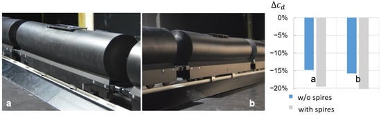
Figure 7.
Side skirt variants. (Left): a with cut-outs for the bogies b without cut-outs; (Right): obtained drag reductions.
3.4. Fairing of Roof Platform
The top of the selected tank wagon geometry is equipped with a platform on the roof, which protrudes into the flow (see Figure 7a,b). It is easy to imagine that it creates some aerodynamic drag, which can be easily reduced by creating a smooth transition to the geometry of the wagon. This was achieved by applying clay to its outer edges and by this, creating a kind of fairing (Figure 8). The obtained drag reduction by this simple modification is in the range of 2% (Figure 8 right), and is only noticeable when the car is subjected to higher wind speeds, which is the case in upstream locations (without spires).
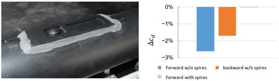
Figure 8.
Fairing of roof platform. (Left): modeled fairing with clay; (Right): obtained drag reductions.
3.5. Inter-Wagon Disc
Mair [24] experimentally showed the potential of drag reduction for a cylindrical bluff body in parallel flow by mounting a disc of a smaller diameter in the near wake. With this simple device, which corresponds to a virtual boat tailing, the base drag was reduced by about 35 %. In a more recent publication by Gillieron [25], a vertical splitter plate was applied parallel to the base of a generic car model, and drag reductions of up to 12% were obtained.
Inspired by these two approaches, the authors of the present paper studied the possibility of drag reduction by placing a disc in the inter-wagon gap. The discs were positioned in the center of the gap between the cars, perpendicular to the direction of the mean flow (Figure 9 and Figure 10). Two mounting configurations were used: the disc was mounted at the upstream end of the car and mounted to the downstream end of the test car. Three different diameters, , and (maximum possible diameter above the buffers) were investigated, following the investigations presented in [24]. The inter-wagon gap x has a length of .
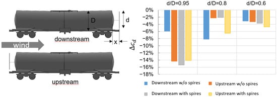
Figure 9.
Mounted inter-wagon discs (left) and drag reductions for different diameters (right).
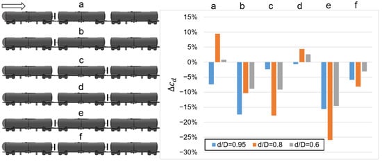
Figure 10.
Configurations of single inter-wagon discs (left) and drag reduction for different configurations (right).
The results show that indeed, the disc is also reducing the drag when positioned in a gap between two bluff bodies. The highest drag reduction is found for the largest disc, with mounted downstream, rendering a reduction of almost in the case with spires, i.e., corresponding to a location near the end of the train (Figure 9). Similar reductions were also measured for the cases where the disc was mounted at the upstream end, regardless of the boundary layer thickness. However, in the case of a thin boundary layer in combination with downstream mounting, the largest drag reduction was found for the medium diameter .
In order to better understand the physics for the drag reduction by the discs, their effect on a single wagon, i.e., when located only in one of the two gaps of a wagon, was also investigated. An overview of six different configurations investigated is shown in Figure 10:
- a: Disc is located in the upstream gap but attached to the upstream wagon;
- b: Disc is located in the upstream gap and attached to the test wagon;
- c: Disc is located in the downstream gap and attached to the test wagon;
- d: Disc is located in the downstream gap but attached to the downstream wagon;
- e: Two discs attached to the test wagon;
- f: Two discs each attached to the upstream vehicle.
Two general observations can be derived from the obtained drag changes in Figure 10: First, the aerodynamic drag of the test wagon is always reduced when the largest disc diameter is applied, regardless of its physical connection. This implies that this disc geometry modifies the flow field in the gap in a manner such that the gap is virtually closed. Most probably, a stationary vortex system is established in the gap (which is divided by the disc), mimicking a smooth “surface” towards the free stream, and thus resulting in an aerodynamic benefit. This is supported by results from the configurations a and d where the disc is not attached to the test wagon; i.e., no force transmission from the disc to the test wagon. In contrast, the drag increases for the smaller diameters in cases a and d, implying that adverse pressure fields are created in the gap for the test wagon.
Second, depending on whether the disc is attached to the front or the rear of the test wagon, and depending on its diameter, the drag is always reduced in configurations b, c, e, and f. Apparently, in these cases, the pressure fields created by and acting on the discs reduce the overall aerodynamic forces of the test wagon. This effect is likely to be dependent on the thickness of the boundary layer, i.e., on the location of the wagon in the train, so that the dependencies of the drag reduction shown in Figure 9 can be expected. Furthermore, it can also be deduced from Figure 10 that in the case of mixed tank wagon trains (in which both wagons with and without discs are in operation), the largest diameter variant would be preferable, since in this case, there are never any disadvantageous effects for adjacent wagons.
3.6. Combination of Side-Skirts and Inter-Wagon Disc
In another set of tests, the potential for drag reduction by combining the inter-wagon disc and side-skirts was studied. In Figure 11, the best results are depicted, which indicated that the drag reduction corresponds to the sum of the effect of the individual devices. In the configuration with a disc of size attached to the head of the test wagon in combination with side-skirts, the drag was reduced by 29%. This implies that the two methods do not interact with each other. It can be expected that the additional fairing of the roof platform would give an overall drag reduction of more than 30%, depending on the position in the train.
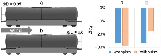
Figure 11.
Inter-wagon disc and side-skirts combined (left); drag reduction through combination (right). a inter-wagon disc at upstream face; b inter-wagon disc at downstream face.
4. Conclusions
Four different modifications or add-on devices were tested, in order to analyze the potential of reducing the aerodynamic drag of a model representing a realistic tank wagon at a 1:25 scale on a stationary ballast and rail model. The modifications were applied to the roof, the underbody, the end faces, and in the inter-wagon gaps of the vehicles.
The results in Table 1 reveal the large potential for drag reduction through the retrofitting of add-on devices to existing tank wagon geometries. For the first time, an add-on device in form of a disc mounted in the area between adjacent wagons was investigated. The device was inspired by the investigation of Mair [24] who used a disc as an after body for near wake control and drag reduction for a bluff body with a cylindrical cross-section. The discs proved to be effective in both driving directions, and also for wagons located near the head or near the end of the train. The largest tested diameter corresponding to 90% of the tank diameter provided the best reductions. Side-skirts for covering the area under the wagon provide a further reduction in drag of around 15%, so that in combination with the inter-wagon discs, total savings of up to over 30% are possible.

Table 1.
Maximal obtained drag reduction for modifications.
The face radius of the wagon has also a large impact on the aerodynamic drag. A radius smaller than the original radius and corresponding to 60% of the tank wagon’s diameter resulted in a drag reduction of about 15% when applied to the upstream end only. However, when the same radius was applied to both faces, or only to the downstream face, the drag was drastically increased. In addition to this unfavorable direction dependency, the small radius physically closes the inter-wagon area, rendering it inaccessible for operating personnel, and it is thus not practical.
Based on the identified drag reduction potentials presented in this paper, a saving potential for the traction energy demand is estimated to be up to 11%. The analysis assumes a train composed of 30 tank wagons and traveling at speeds between 80 and 120 km/h on a straight track. The details of the analyses are provided in [10].
The measured drag reductions were obtained at zero yaw and without the simulation of the relative motion between the train model and ballast and rail. Thus, future investigations are expected to assess the potential of the presented modifications under yawed conditions and with moving ground. The authors expect that the drag reduction will be lower but still significant. In the above-mentioned study by Gillieron [25], it was observed that the vertical plate in the wake of the generic car model loses about 2 % of its drag reducing potential when the vehicle is subjected to 10° yawed wind. This could be an indication for the expected decrease in drag reduction for the proposed inter-wagon disc. Cross wind velocities depend strongly on the driving speed and geographical conditions, but average values in the range of 12° are not unusual, as found for a freight train in Australia [17].
Future studies should also analyze the flow field modification through the inter-wagon disc for a better understanding of the underlying aerodynamic drag reducing mechanism. Furthermore, the effect of the inter-wagon disc should also be investigated for other freight wagon geometries.
Author Contributions
Conceptualization, methodology, investigation, formal analysis and writing—original draft preparation, C.N.N. and J.T.; funding acquisition and resources, H.S. (Harald Schulze) and H.S. (Hanno Schell). All authors have read and agreed to the published version of the manuscript.
Funding
This research was funded by the German Federal Ministry for Digital and Transport (BMDV) within the project “Aufbau und Erprobung von Innovativen Güterwagen”.
Institutional Review Board Statement
Not applicable.
Informed Consent Statement
Not applicable.
Data Availability Statement
Not applicable.
Acknowledgments
We acknowledge the support by the team of Markus Hecht from Technische Universität Berlin, Institute for Land- and Sea Transportation in preparing the model geometry and their valuable input on train operations.
Conflicts of Interest
The authors declare no conflict of interest.
References
- Lukaszewicz, P. Energy Consumption and Running Time for Trains. Ph.D. Thesis, Railway Technology, Department of Vehicle Engineering, Stockholm, Sweden, 2001. [Google Scholar]
- Davis, W.J. The Tractive Resistance of Electric Locomotives and Cars; General Electric: Boston, MA, USA, 1926. [Google Scholar]
- EN 14067-2:2003; Railway Applications-Aerodynamics, Part 2: Aerodynamics on Open Track. Beuth Publishing: Berlin, Germany, 2003. [CrossRef]
- Netz21-Die Netzstrategie der Deutschen Bahn; Vereinigung Europäischer Eisenbahngüterverkehrsunternehmen e.V.: Berlin, Germany, 2008.
- Barkan, C. Railroad Transportation Energy Efficiency Sustainable Seminar Series; Illinois Sustainable Technology Center: Champaign, IL, USA, 2009. [Google Scholar]
- Beagles, A.E.; Fletcher, D.I. The aerodynamics of freight: Approaches to save fuel by optimising the utilisation of container trains. Proc. Inst. Mech. Eng. Part F J. Rail Rapid Transit 2013, 227, 635–643. [Google Scholar] [CrossRef]
- Soper, D. The Aerodynamics of a Container Freight Train. Ph.D. Thesis, University of Birmingham, Birmingham, UK, 2014. [Google Scholar]
- Li, C.; Burton, D.; Kost, M.; Sheridan, J.; Thompson, M.C. Flow topology of a container train wagon subjected to varying local loading configurations. J. Wind Eng. Ind. Aerodyn. 2017, 169, 12–29. [Google Scholar] [CrossRef]
- Bell, J.R.; Burton, D.; Thompson, M.C. The boundary-layer characteristics and unsteady flow topology of full-scale operational inter-modal freight trains. J. Wind. Eng. Ind. Aerodyn. 2020, 201, 104164. [Google Scholar] [CrossRef]
- Tschepe, J.; Leiste, M.; Baumgärtel, Y.; Nayeri, C.N.; Hecht, M. Aufbau und Erprobung von Innovativen Güterwagen—Aerodynamische Optimierung von Güterwagen; Technische Universität Berlin: Berlin, Germany, 2017; Available online: https://www.bmvi.de/goto?id=456222 (accessed on 26 July 2022).
- Bendel, H. Untersuchungen zur Verringerung des aerodynamischen Widerstandes von Güterwagen. Z. Eisenb. Verk. 1990, 114, 124–132. [Google Scholar]
- Watkins, S.; Saunders, J.; Kumar, H. Aerodynamic drag reduction of goods trains. J. Wind Eng. Ind. Aerodyn. 1992, 40, 147–178. [Google Scholar] [CrossRef]
- Hecht, M.; Maengel, C.; Jakatt, H.; Nayeri, C.; Shoeib, R.; Alsdorf, G.; Wullstein, U. Transport Container, Vehicle, Traction Group, Method for Loading a Transport Container, and Method for Transporting Bulk Material. U.S. Patent 9,580,084, 28 February 2017. [Google Scholar]
- Gielow, M.; Furlong, C. Results of Wind Tunnel and Full-Scale Tests Conducted from 1983 to 1987 in Support of the Association of American Railroads’train Energy Program; Technical Report No. AAR R-685; Association of American Railroads Research Center: Washington, DC, USA, 1988. [Google Scholar]
- Maleki, S.; Burton, D.; Thompson, M.C. Flow structure between freight train containers with implications for aerodynamic drag. J. Wind Eng. Ind. Aerodyn. 2019, 188, 194–206. [Google Scholar] [CrossRef]
- Maleki, S.; Burton, D.; Thompson, M.C. On the flow past and forces on double-stacked wagons within a freight train under cross-wind. J. Wind Eng. Ind. Aerodyn. 2020, 206, 104224. [Google Scholar] [CrossRef]
- Quazi, A.; Crouch, T.; Bell, J.; McGreevy, T.; Thompson, M.C.; Burton, D. A field study on the aerodynamics of freight trains. J. Wind Eng. Ind. Aerodyn. 2021, 209, 104463. [Google Scholar] [CrossRef]
- Tschepe, J.; Nayeri, C.N.; Paschereit, C.O. On the influence of Reynolds number and ground conditions on the scaling of the aerodynamic drag of trains. J. Wind Eng. Ind. Aerodyn. 2021, 213, 104594. [Google Scholar] [CrossRef]
- Irwin, H. The Design of Spires for Wind Simulation. J. Wind Eng. Ind. Aerodyn. 1981, 7, 361–366. [Google Scholar] [CrossRef]
- Hucho, W.H. Strömungsphänomene. In Aerodynamik der stumpfen Körper: Physikalische Grundlagen und Anwendungen in der Praxis; Vieweg+Teubner Verlag: Wiesbaden, Germany, 2012; pp. 12–93. [Google Scholar] [CrossRef]
- Hoerner, S. Fluid-Dynamic Drag; Hoerner Fluid Dynamics: Bakersfield, CA, USA, 1965. [Google Scholar]
- Cooper, K.R.; Leuschen, J. Model and Full-Scale Wind Tunnel Tests of Second-Generation Aerodynamic Fuel Saving Devices for Tractor-Trailers; Technical Report; SAE Technical Paper: No. 2005-01-3512; SAE International: Warrendale, PA, USA, 2005. [Google Scholar]
- Kim, J.J.; Kim, J.; Hann, T.; Kim, D.; Roh, H.S.; Lee, S.J. Considerable drag reduction and fuel saving of a tractor–trailer using additive aerodynamic devices. J. Wind Eng. Ind. Aerodyn. 2019, 191, 54–62. [Google Scholar] [CrossRef]
- Mair, W. The effect of a rear-mounted disc on the drag of a blunt-based body of revolution. Aeronaut. Q. 1965, 16, 350–360. [Google Scholar] [CrossRef]
- Gilliéron, P.; Kourta, A. Aerodynamic drag reduction by vertical splitter plates. Exp. Fluids 2010, 48, 1–16. [Google Scholar] [CrossRef]
Publisher’s Note: MDPI stays neutral with regard to jurisdictional claims in published maps and institutional affiliations. |
© 2022 by the authors. Licensee MDPI, Basel, Switzerland. This article is an open access article distributed under the terms and conditions of the Creative Commons Attribution (CC BY) license (https://creativecommons.org/licenses/by/4.0/).