Article

Identifying the Origin of Turbulence Using Convolutional Neural Networks

Naval Postgraduate School, One University Circle, Monterey, CA 93943, USA
*
Author to whom correspondence should be addressed.
Fluids 2022, 7(7), 239; https://doi.org/10.3390/fluids7070239
Submission received: 10 June 2022 / Revised: 28 June 2022 / Accepted: 8 July 2022 / Published: 13 July 2022

Abstract

:
Though turbulence is often thought to have universal behavior regardless of origin, it may be possible to distinguish between the types of turbulence generated by different sources. Prior work in turbulence modeling has shown that the fundamental “constants” of turbulence models are often problem-dependent and need to be calibrated to the desired application. This has resulted in the introduction of machine learning techniques to attempt to apply the general body of turbulence simulations to the modeling of turbulence at the subgrid-scale. This suggests that the inverse is likely also possible: that machine learning can use the properties of turbulence at small scales to identify the nature of the original source and potentially distinguish between different classes of turbulence-generating systems, which is a novel pursuit. We perform numerical simulations of three forms of turbulence—convection, wake, and jet—and then train a convolutional neural network to distinguish between these cases using only a narrow field of view of the velocity field. We find that the network is capable of identifying the correct case with 86% accuracy. This work has implications for distinguishing artificial sources of turbulence from natural ones and aiding in identifying the mechanism of turbulence in nature, permitting more accurate mixing models.

1. Introduction

Conventional wisdom would suggest that turbulence retains little memory of its origin. This is the fundamental assumption of the majority of turbulence models that exist in the literature: the turbulent cascade is a general process where energy enters at the injection scale and eventually dissipates at the dissipation scale in a way that is essentially scale- and problem-independent. We challenge this assumption by performing numerical simulations of stratified turbulence with three different origins: a wake, local convection, and a jet. We then successfully train a Convolutional Neural Network (CNN) to distinguish the turbulence that arises from a these three systems from other forms of turbulence using only local measurements.
This challenge to the global nature of turbulence has been a topic of recent interest. Since the early work by Smagorinsky [1], which provided a universal estimate for the behavior of turbulence, turbulence modeling has become an important component of large-scale numerical simulations of fluid dynamics. Such modeling includes large-eddy simulations (LES)—where the dissipation scale of turbulence is not resolved and a subgrid-scale model is employed to cover the behavior of the turbulent cascade from the grid scale to the dissipation scale—and Reynolds-averaged Navier–Stokes—where the non-linear terms of the governing equations are approximated with analytical closures. Both these families of turbulence modeling require calibration of the model constants to simulations and experiments in order to apply the models to problems in reality. An important consideration of this work is that these “constants” are typically problem-dependent. For examples, see the work of Galperin and Orszag [2] and Canuto and Cheng [3]. In particular, Canuto and Cheng [3] demonstrated that the problems of plane-strain and homogenous shear can show substantial differences in these constants and therefore in the behavior of the turbulence as a whole. Because turbulence models must be tailored to the individual problem in ways that are difficult to generalize, machine learning techniques have been employed for more general applications.
Much of the history of the application of machine learning to turbulence modeling is compiled in the recent review by Beck and Kurz [4]. A number of studies have successfully used machine learning to determine the closures required in LES and RANS models [5,6,7,8,9,10,11,12,13]. Such studies are taking the large body of data regarding turbulence (both experimental and numerical) and determining the relatively small number of turbulence metrics that are useful for controlling the behavior of the turbulent cascade, which is an ideal application for machine learning techniques. Some of these studies take direct numerical simulations (DNS) or laboratory experiments, filter them at the appropriate grid-scale, and determine the turbulence metrics, such as the Reynolds stress. An artificial neural network (ANN) is then used. The filtered spatial information is input to the network, and the turbulence metrics are output. Others, such as Parish and Duraisamy [7], use these results to develop functional terms that can be used in LES and RANS models to adapt more typical turbulence closures. All this prior work accepts that turbulence is inherently affected by its surroundings, and so it stands to reason that machine learning techniques could also be applied to the classification of turbulence.
Attempts to use machine learning to identify turbulence are remarkably uncommon. It has been known that some biological organisms (such as harbor seals, as shown in [14]) are capable of identifying and following wake turbulence, and this has motivated a series of biomimetic studies in an attempt to glean information about turbulent regions. Recently, studies by Colvert et al. [15] and Alsalman et al. [16] showed that ANNs and clustering techniques could be used to successfully identify types of turbulent structures based on limited data in airfoil wakes. Li et al. [17] used a machine learning technique known as extreme gradient boosting to identify the region of a wake where turbulence is present and showed that these techniques were more generally applicable than ad-hoc determinations. Given such success, this raises the question as to how capably machine learning techniques can distinguish between turbulence produced by different sources, such as wakes, jets, overturning convection, shear, etc.
In this study, we perform a series of numerical simulations of various forms of turbulence. These simulations generate convective turbulence, jet turbulence, and wake turbulence, and we measure the velocity fields of each simulation. We design and train a convolutional neural network to distinguish unique characteristics of these three forms of turbulence. Though many studies of turbulence modeling have used the large-scale characteristics of a region of turbulence to determine the small-scale behavior, the attempt to use the small-scale characteristics to classify the large-scale behavior is relatively new. Past studies have been limited only to distinguishing characteristics between the same type of source, whereas this study shows that it is possible to use comparable techniques to distinguish between different sources with 86% accuracy. Section 2 describes the numerical simulation methodology used to create data samples for wakes, jets, and convective turbulence. Section 3 discusses the results of the numerical simulations, details the convolutional neural network used in this study, and provides the results of the training and validation of the neural network. Section 4 offers a discussion and conclusion of the results.

2. Materials and Methods

We employ the Massachusetts Institute of Technology General Circulation Model (MITgcm), which is a flexible computational fluid dynamics solver that can simulate oceanographic phenomena from basin-wide scales to micro-scales [18]. This code is widely used in the oceanographic community and has undergone rigorous verification and validation [19]. MITgcm uses a finite-volume method and can be configured to solve the equations of motion using the Boussinesq approximation in the absence of planetary rotation. These approximations are justified by the relatively small scale (100 m) and short time frame (<1 h) of the simulations, which permit ignoring the Coriolis term and nonlinearities in the equation of state. In addition, the typical velocity of the flow is much smaller than the sound speed, which permits the assumption of incompressibility. These equations of motion are given by
· u = 0 ,
ρ ρ 0 ρ 0 = α T T 0 ,
T t + u · T = k T 2 T + Q ,
u t + u · u = p ρ 0 ρ ρ 0 g k ^ + ν 2 u + F i ^ ,
where u is the velocity vector, ρ is the density, ρ 0 is a reference density, α is the thermal expansion coefficient, T is temperature, k T is the thermal diffusivity, k ^ is the unit vector in the z-direction, i ^ is the unit vector in the x-direction, and ν is the kinematic viscosity. Equation (1) describes mass continuity, Equation (2) is the linear equation of state, Equation (3) describes the temperature evolution, and Equation (4) is the momentum evolution equation. The Q and F terms are external heating and forcing functions, respectively, which are used to generate turbulence.
Each simulation is run in a three-dimensional domain in x, y, and z with a background temperature gradient of 0.03 °C m 1 and with small perturbations taken from a uniform distribution. The grid is rectilinear with uniform 0.33-m resolution in all spatial directions, which is comparable to or finer than our prior work (e.g., [20]). Figure 1 depicts the simulated domain for all cases. We define L x , L y , and L z as the lengths of the domain in the x, y, and z directions, respectively. The domain sizes for each simulation are included in Table 1, which fully describes the characteristic parameters of each simulation.

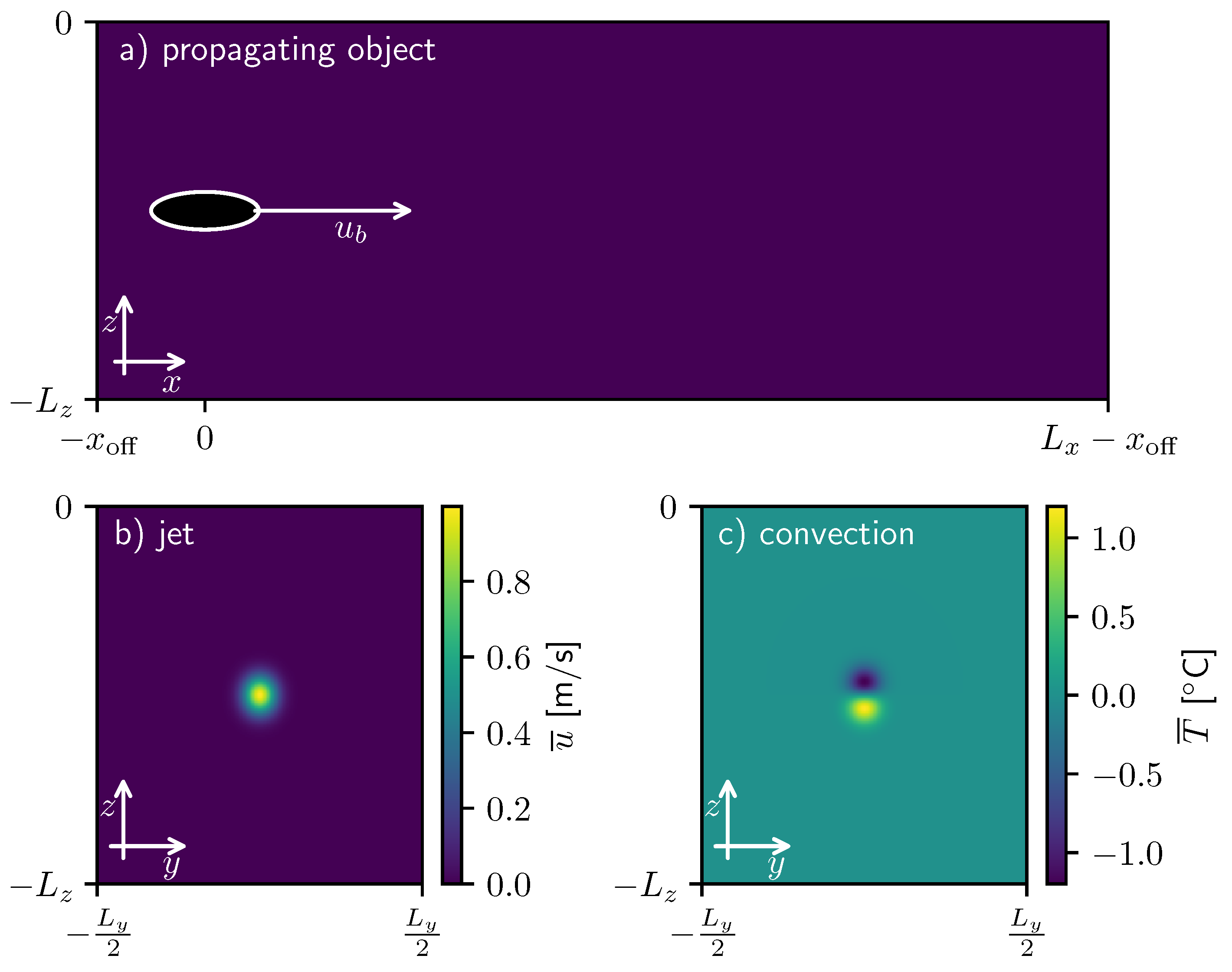
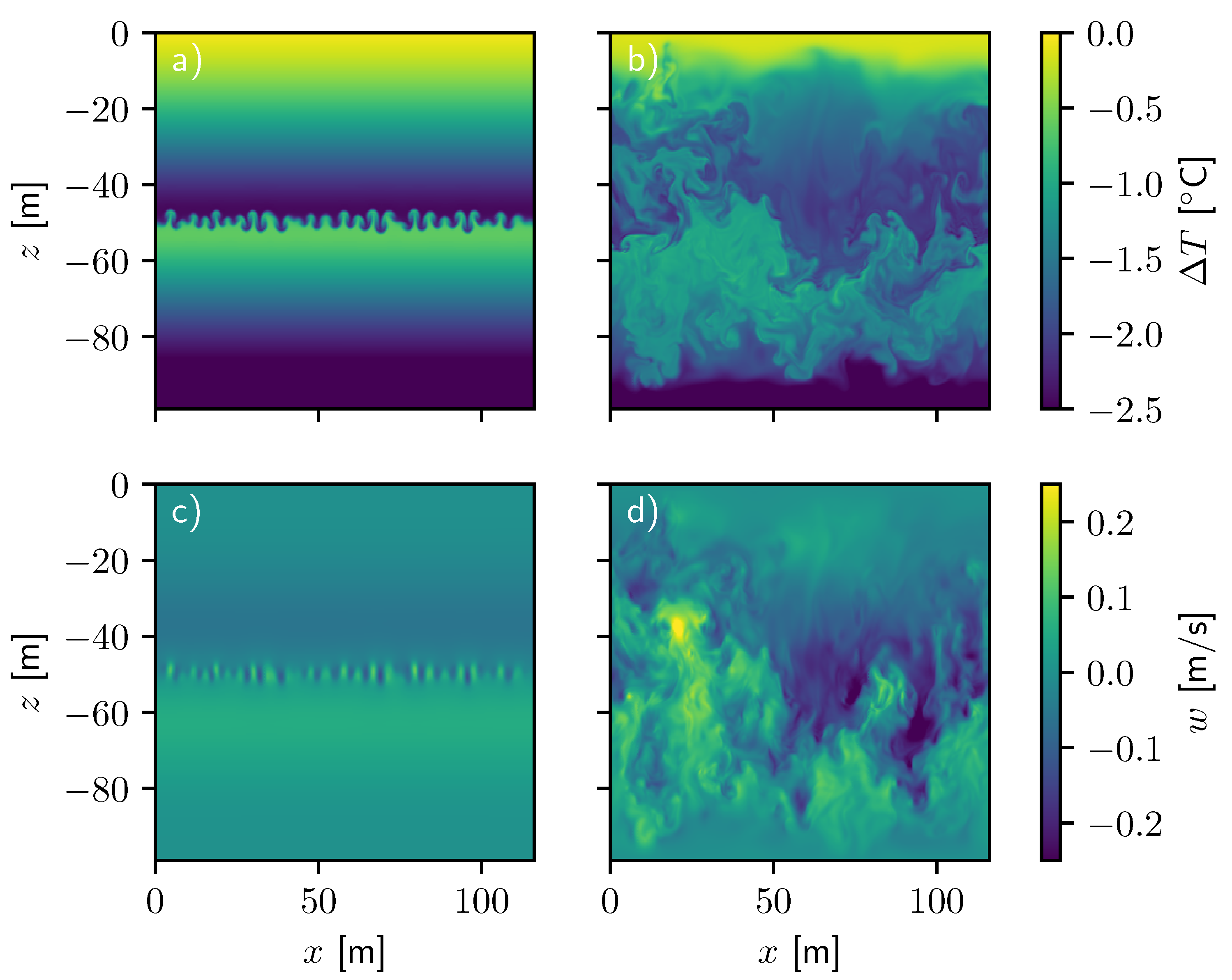
2.1. Propagating Object

To study the turbulence of a wake, an ellipsoid is towed through a quiescent medium at a velocity u b along its longest axis. The forcing F simulates the effects of a moving immersed boundary condition within the mesh, which is stationary. Though a moving mesh might allow for finer resolution near the body (and hence permit a higher Reynolds number), such a numerical setup can have substantial issues in incompressible calculations (see, e.g., [21]). Thus, the boundary condition is implemented to translate through the mesh and is enforced using a local forcing function. The forcing is given by the difference between the local fluid velocity and the desired object velocity, u b , divided by a characteristic relaxation time, τ :
F = u u b τ , inside object , 0 , elsewhere ,
The forcing is present only within the ellipsoidal geometry of the object, which is bounded by
1 < x x b 2 σ x 2 + y y b 2 σ 2 + z z b 2 σ 2 ,
where x b , y b , and z b describe the position of the propagating body, σ is the length of the principle semi-axes in y and z, and σ x is the principle semi-axis in x. No boundary condition is imposed on the temperature field at the ellipsoid surface; instead, the interior temperature is permitted to diffuse naturally. We choose an elongated body with σ = 5 m and σ x = 50 m. The position of the propagating ellipsoid in the x coordinate is given by
x b = u b t + x 0 , b ,
where x 0 , b = 0 m is the starting point in x, which is offset x off = 100 m away from the x boundary. The origin of the domain is set to be the surface point above the body. The position of the body in y, y b , is 0 m, and the position in z, z b , is 50 m. In this study, three propagating body simulations are performed with different values of u b : 3 ms 1 , 5 ms 1 , and 7 ms 1 .

2.2. Jet

To generate a form of turbulence to contrast with the wake, we consider the turbulence generated by a continuously forced jet. We simulate a jet flow by creating an initial velocity profile defined as
u ¯ = A u exp ( y y 0 ) 2 + ( z z 0 ) 2 σ 2 ,
where u ¯ is the bulk velocity in the x-direction, A u is the amplitude of the jet (1 ms 1 ) at the jet axis center, and σ describes the characteristic radius of the jet, which we placed at y 0 = 0 m and z 0 = 50 m . The jet amplitude is perturbed by a small sinusoid along the x direction to seed instability. We continuously force the jet and allow perturbations to evolve into turbulence over time. The forcing for the jet, F, is given by
F = γ j τ u ¯ ,
where γ j is defined as
γ j = u u ¯ u ¯ d V u ¯ 2 d V ,
which allows us to adjust the mean velocity without affecting the microstructure that is valuable to this study. We perform one simulation of this kind with A u = 1 m s 1 .

2.3. Convection

As our second example of non-wake turbulence, we continuously generate convective motions by localized heating and cooling. To produce convective turbulence, we force a dipole in the temperature field, with a region of persistent cooling directly above a region of persistent heating. This forcing generates local instability, driving vertical motions and turbulent flow. Persistent thermal forcing, Q, was introduced to induce convection and is defined as follows:
Q = γ c τ T ¯ ,
where γ c is given by
γ c = T T ¯ T ¯ d V T ¯ 2 d V ,
and T ¯ is the desired temperature perturbation dipole, described by
T ¯ = 2 A c σ 2 z z 0 e ( y y 0 ) 2 + ( z z 0 ) 2 σ 2 ,
where A c determines the amplitude of the convective forcing, and T is the thermal perturbation away from the horizontally averaged temperature field, T , given by
T = T T .
Stratification-driven turbulence such as this likely carries different signatures than the wake and jet cases as forcing is largely vertical for convection and horizontal for wakes and jets. We perform one simulation of this kind with A c = 7 m C .

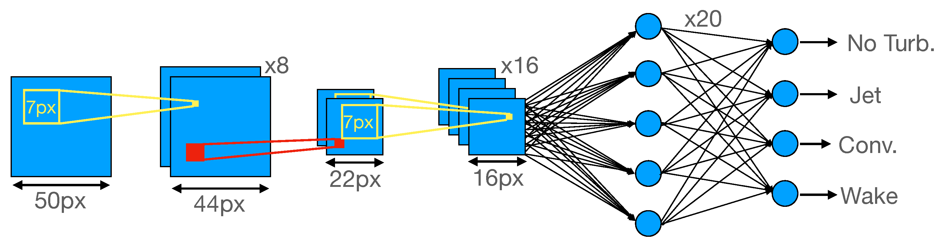
2.4. Artificial Neural Network Methodology
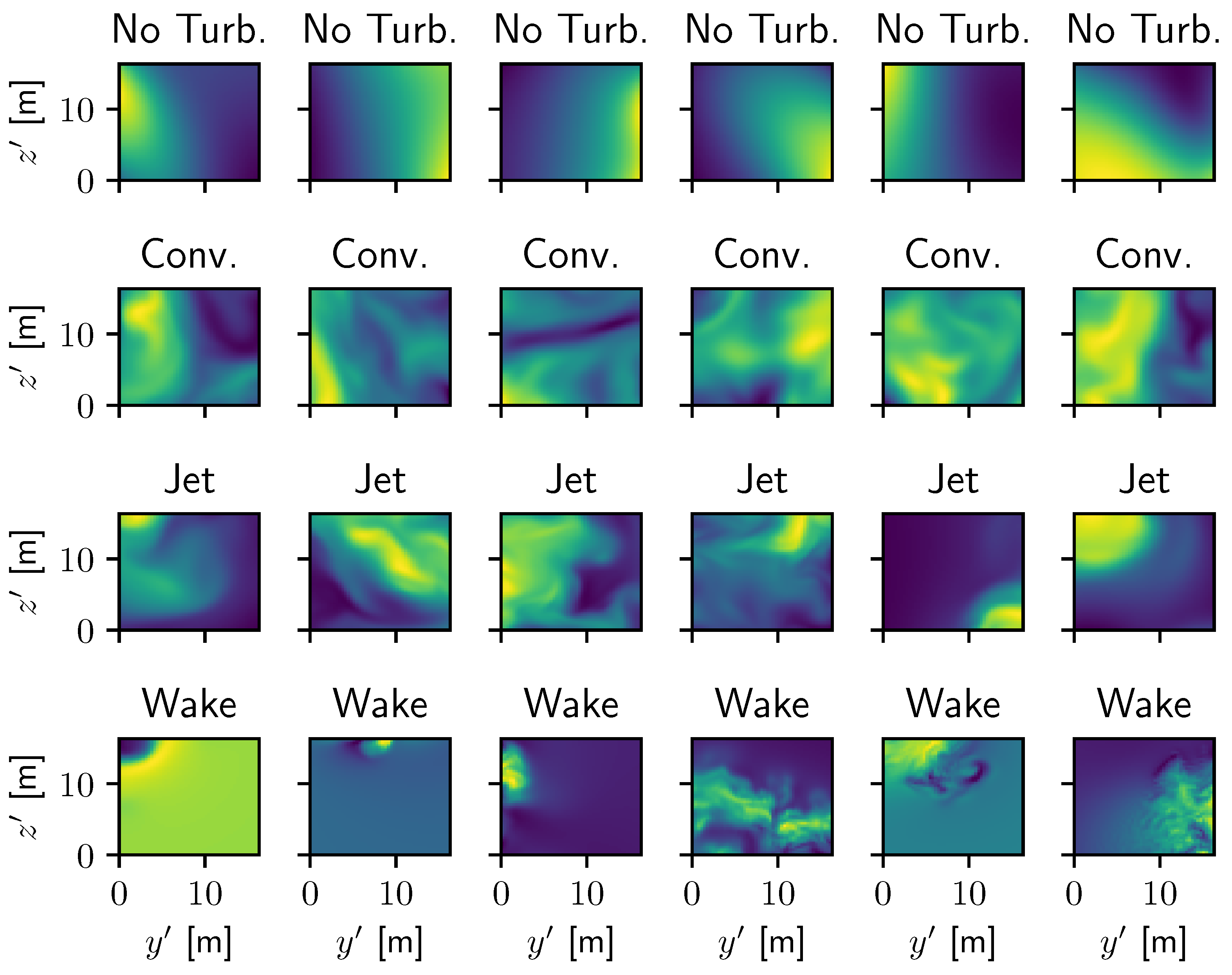
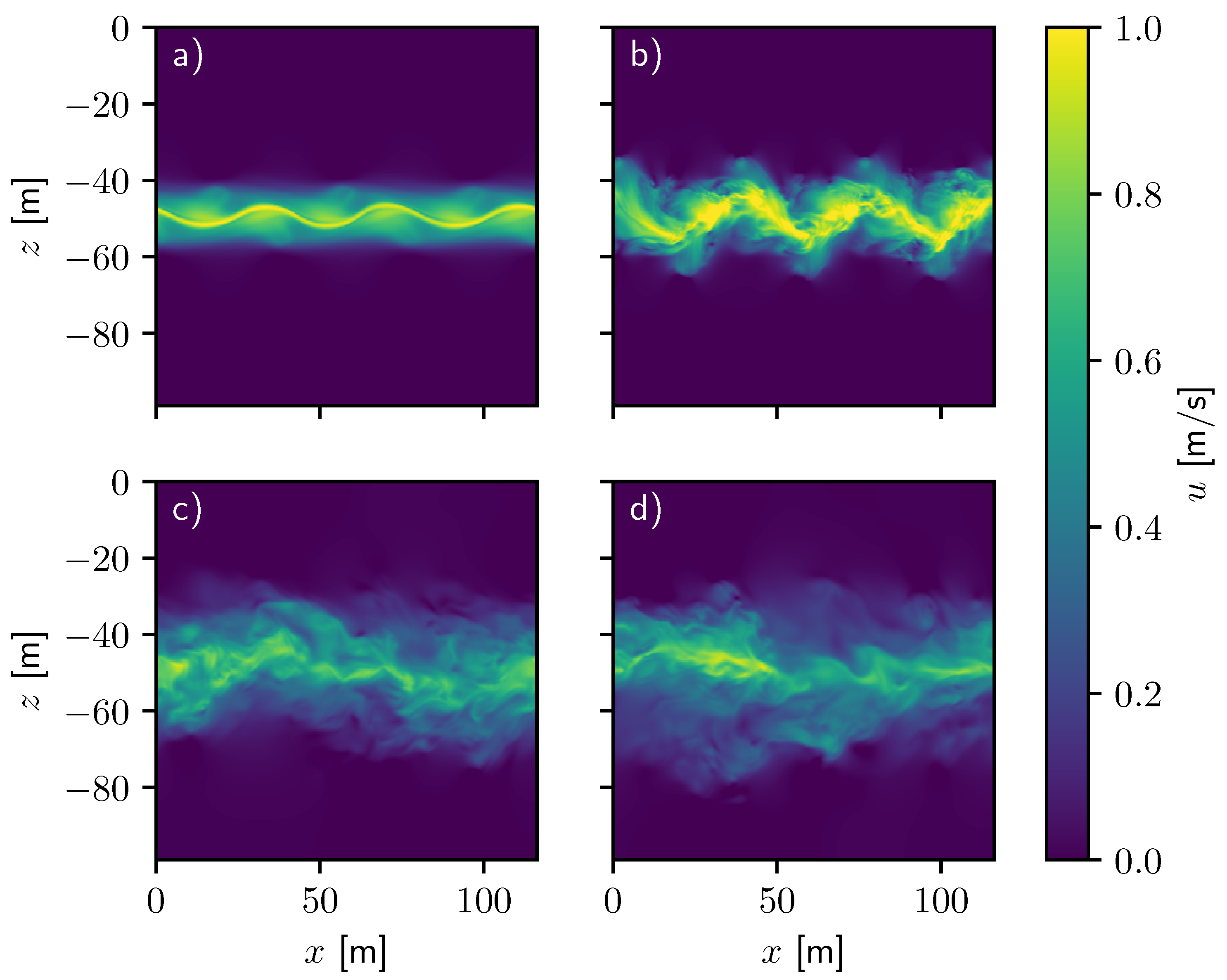
The architecture of the neural network is diagrammed in Figure 2 and constructed using TensorFlow [22]. The input layer to the network is a two-dimensional segment of an x-normal slice of the u field, and each sample is labeled according to the type of simulation from which it originates. These segments are constructed by decomposing the slices into 50-pixel-by-50-pixel images, as shown in Figure 3, in terms of local coordinates y and z . The first several layers of the network alternate between convolution layers with filter sizes of 7-by-7 pixels and max pooling layers that pool over 2-by-2-pixel regions. The first convolution layer uses 8 filters and the second, 16 filters. After the final convolution layer, a fully connected layer of 20 neurons is used before connecting to the classification layer. The classification layer uses a soft-max activation function to convert the final values into the probability that the image belongs to one of the four possible classes: no notable turbulence (N), wake turbulence (W), jet turbulence (J), or convective turbulence (C). Except for the final classification layer, the rectified linear unit (ReLU) activation function is used. To protect against overfitting and speed up training, batch normalization layers are used between convolution layers, and a dropout layer is introduced between the fully connected layer and the classification layer. The use of batch normalization in convolutional neural networks is fairly commonplace (see, e.g., [23,24,25]), and the benefits and details of batch normalization are described in Ioffe and Szegedy [26]. The batch normalization works as follows: given a vector of layer outputs from a convolution layer, X i , k , for observation i in a batch of 32 and filter k, the batch normalization transforms X i , k according to
X ^ i , k = X i , k X ¯ k V k + ε ,
where X ¯ k and V k are the mean and variance of the values in the batch across space and observations. The quantity ε = 0.001 is a small number used for numerical stability in cases with small variance. These values are not averaged across filters and so can take on different values for each filter. Before applying the ReLU activation function, the X ^ i , k are scaled and offset by learnable parameters β and δ as follows:
Y i , k = δ X ^ i , k + β .
Because this serves to normalize the activations across the batch, it makes it more challenging for the network to develop filters that are trained to specific characteristics of an individual observation, preventing overfitting. This also typically decreases the time taken to train the network.
Our dataset is composed of the x-velocity fields for the various simulations performed in this study. The fields are gathered at varying times and slice displacements with respect to x and t at which the samples are substantially decorrelated (cross-correlations of <0.1), as described in Table 2. Each x-normal slice (a 100-m square) is broken up into individual samples, which are spaced 8 m apart on average, and the centers of these samples are randomly shifted by up to 8 m in y and z to ensure important features (such as the wake center) are not always located in the same set of pixels. Additionally, for many of the slices through these simulations, there are large regions where no substantial turbulence is present, which we identify by regions where the maximum of | u | is less than 0.01 m s 1 or the maximum of | u | is less than 0.005 s 1 , and we disregard all regions where the maximum of | u | is less than 0.001 m s 1 as completely quiescent. The data are normalized by subtracting the mean and dividing by the standard deviation. Together, this produces a dataset with 28,304 samples of regions where no substantial turbulence is present, 319,057 samples of convective turbulence, 60,177 samples of jet turbulence, and 13,997 samples of wake turbulence. To avoid an imbalance of the individual types of turbulence, we randomly select a subset of approximately 14,000 samples of each of these to keep for our machine learning algorithm. From the chosen 56,544 samples, approximately 20% of the samples of each case are selected as our validation set, and the remaining 45,213 are augmented by being flipped horizontally, vertically, and in both directions to produce a final training set of 180,852 samples of 17 m by 17 m turbulence and a final validation set of 11,331 samples. Both horizontal and vertical reflections of the u field in y and z are also valid solutions to the equations and representative examples of turbulence; such augmentation is common practice for training CNNs. The CNN training is performed using the Adam optimization algorithm with a learning rate of 0.001, and the loss function is a categorical cross-entropy function. The output of the final layer of the network acting on an image, s , is a set of probabilities, p i ( s ) , which measure the likelihood that the image belongs to each possible classification (distinguished with index i). Because of the soft-max activation function, i = 1 K p i ( s ) = 1 , where K = 4 is the number of possible classifications. If there are S total images in the batch (32) or validation set (11,331), the loss function is given by
loss = 1 S j = 1 S i = 1 K t i ( s j ) log 2 p i ( s j ) ,
where s j is the jth image in the batch, and t i ( s j ) = 1 when s j is a member of class i and 0 otherwise. We train the model for 100 epochs at which point the loss value for the validation set no longer improves, and the training is ended to prevent overfitting to the training set. We choose a single, fully connected layer with 20 neurons before the classification layer to minimize overfitting and complexity. Increasing the number of neurons in this layer to 30 provides only a 0.4% increase in accuracy of classification, which is insufficient to justify the additional cost. Adding a second hidden layer with 20 neurons results in substantial overfitting, where the accuracy of classifying the training set is comparable to the other configurations, but the accuracy is 10% lower for the validation set.

3. Results

Figure 4 displays the x component of the velocity field of the simulation with an ellipsoid propagating at 5 ms 1 . At early times, the flow around the body is laminar prior to the onset of turbulence, which is evidenced by the structure of the wake at x < 100 m , so we only use data after x = 200 m for analysis. Soon thereafter, near-wake turbulence forms behind the propagating ellipsoid (see Figure 4a) and remains in the domain throughout the simulation. The near wake structures have not yet experienced the effects of buoyancy forces and, therefore, have not yet transitioned to intermediate wake structures. We see that the smallest scale features created immediately after the passage of the body dissipate quickly, and the larger features persist and are generally of comparable size to the body. These larger scale features alternate vertically in a structure akin to a von Kárman vortex street, which is typically seen in turbulent wakes. These localized, highly turbulent structures generate a signature which is remarkably different from generic space-filling turbulence. They will serve as important signatures to allow the neural network to distinguish wakes from different forms of turbulence.
Figure 5 displays the production of turbulent flow from a continuously forced 1 ms 1 jet. At the beginning of the simulation, the initial sinusoidal perturbations in the jet amplitude grow, and large vortical structures form at the jet edges (see Figure 5a). Nonlinear interactions continue to influence the shape of the jet until the flow becomes turbulent (see Figure 5b). The early jet in Figure 5a,b is narrow, but it widens over time as fluid becomes entrained into the turbulent flow, which is evidenced by the broadened structures in Figure 5c,d. The continuously forced jet continues to generate turbulent flow in a broad but well-defined region, with the most intense flow remaining in the vicinity of the jet axis. This structure is relatively common in typical jet turbulence (see, e.g., [27]), where the turbulent and non-turbulent regions are separated by the Turbulent/Non-Turbulent interface. For the jet to expand, it must entrain surrounding material, and this entrainment is largely comprised of small-scale “nibbling” behavior [28,29]. Because the expansion is comprised of many small mixing events, the wake expands roughly uniformly, which is distinct from the more focused turbulent events in the prior wake simulation.
For vertically driven flows, we find that persistent forcing of convection also produces turbulent structures from a stratified fluid. The temperature field, shown as the perturbation from the surface temperature, Δ T , in Figure 6a shows fluid at the onset of convective instability, where plumes of warm and cool fluid have introduced mixing as indicated by the velocity field shown in Figure 6c. The fluid near the upper and lower boundaries remains stratified as it has not yet been mixed by convective turbulence. As time progresses to Figure 6b,d, the turbulence fills the domain isotropically. Unlike in the other cases, the thermal forcing leads to direct vertical motion rather than turbulent vertical entrainment. This causes much more rapid expansion throughout the domain than in the wake or jet cases. In addition, this forcing results in a nearly isothermal region. This permits more isotropic turbulence than in either of the other cases, which demonstrate stratified turbulence.
Figure 7 shows the kinetic energy density spectra of the turbulent flows, which help to identify properties of turbulence that might prove useful to classification. To determine the kinetic energy spectrum, we define the specific kinetic energy, K, as
K = 1 2 u 2 + v 2 + w 2 ,
from which the kinetic energy density spectrum at position x and at time t is given by
E K ( t , x , k ) = E k ( t , x , k y , k z ) F ( K ( t , x , y , z ) ) ,
where k y and k z are the y and z components of the wavevector, k , and F is the two-dimensional discrete Fourier transform in y and z. We separate k into 50 discrete bins, where the ith bin has a wavenumber of k i = ( i k max ) / 50 for k max = 9.4 m 1 . The mean kinetic energy in each bin, E ¯ K ( t , x , k i ) , is the mean of E K ( t , x , k y , k z ) for all modes that meet the condition k i < k y 2 + k z 2 < k i + 1 , and we can further average these spectra in space at intervals of 50 m in x to yield E ¯ K ( t , k y , k z ) . We calculate the mean and standard deviation, E σ , of the spectra from these slices, and then plot these in Figure 7. The energy injection scale for these cases is at a wavenumber of 0.63 m 1 , determined by the size scale of the forcing ( 2 σ ). Energy cascades from the injection scale to higher wavenumbers where larger turbulent structures break into smaller structures until they reach the Kolmogorov length scale, where the energy is dissipated. We also see energy at smaller wavenumbers than the injection scale, which indicates an inverse energy cascade. The energy spectrum of convective turbulence is considerably shallower than that of the jet.
In Figure 7, we also plot the spectra for the wake simulation with u b = 5 m / s at varying times since the propagating body has passed. We find that, as time elapses, the kinetic energy density decreases. These two-dimensional spectra are calculated from slices taken normal to the x-axis at 100-m intervals starting at x = 250 m at a global time of t = 100 s (and with the time elapsed since the object has passed varying from t s = 10 s to t s = 50 s ) to ignore the startup transient features. The general shape of the spectrum in the wake case shows a slope that is roughly consistent with the power law of convective turbulence. We also see variability in the energy density structure of the wake case. For example, a local minimum exists near wavenumber 2 m 1 for the spectrum calculated at 10 s since the passage of the propagating body. Later spectra do not appear to have such a local minimum. Since the inertial range of the spectra differs between the wake case and the environmental cases, especially at higher wavenumbers, an artificial neural network may be able to distinguish wake turbulence from environmental turbulence based on small-scale features.

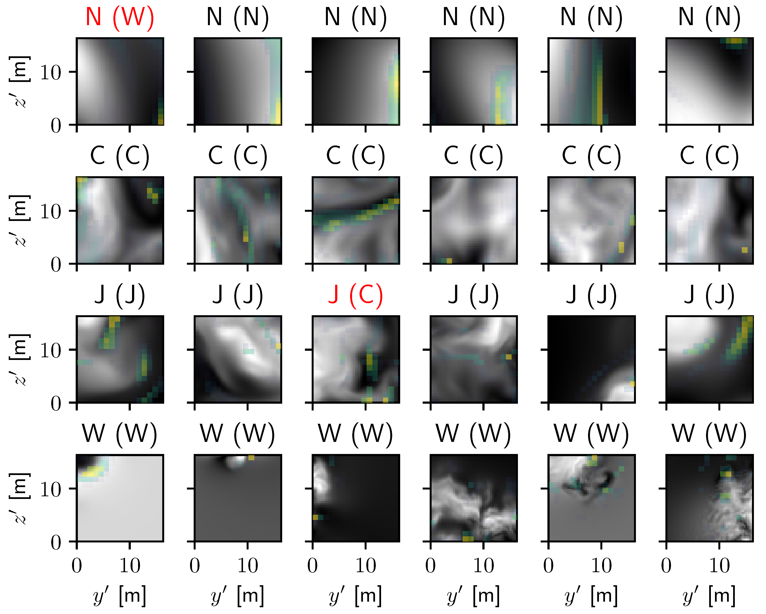
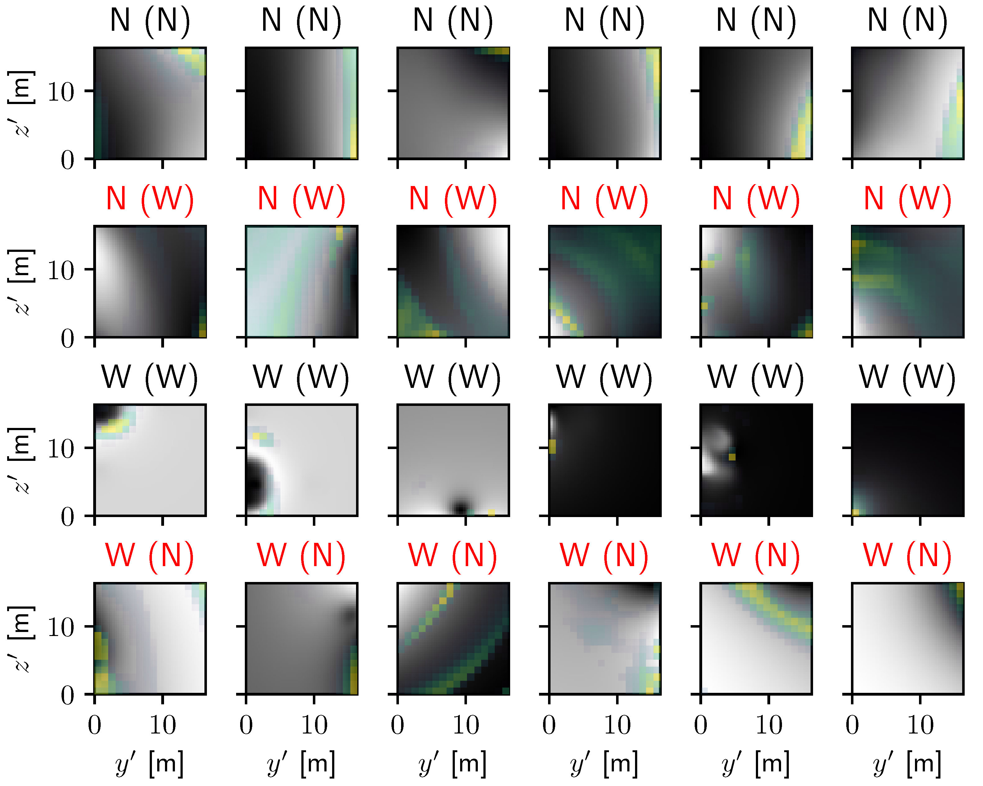
Convolutional Neural Network Results

Table 3 contains the confusion matrix of the neural network on the validation set after training on the training set, showing the number of cases classified correctly and incorrectly. The model performs at an overall 86% accuracy. Wakes, jet turbulence, and convective turbulence are classified correctly 76.9%, 84.0%, and 95.0% of the time, respectively, demonstrating that wake turbulence is the most difficult to classify and that the continuously forced convective turbulence is more easily identified. The classifications that prove most challenging for the network are distinguishing between wake turbulence and no turbulence, jet turbulence and convective turbulence, and jet turbulence and wake turbulence (in order of increasing skill).
These results can also be visualized through the use of a receiver operating characteristic curve (or ROC curve), which measures how the true positive and false positive rates of binary classification vary with an arbitrary threshold. All predictions from the network produce a probability that a given image s belongs to class i, p i ( s ) . We begin by considering just two classes, i and j, and construct the ROC curve for each possible pair of classes in Figure 8a. We restrict our sample to images that are instances of classes i and j, and the probability that our image belongs to class i is then
p i , j ( s ) = p i ( s ) p i ( s ) + p j ( s ) .
We consider a threshold θ i , j for p i , j ( s ) , so s is classified as an instance of class i if p i , j ( s ) > θ i , j . Any image that is correctly identified as a member of class i is considered a “true positive,” where any image incorrectly identified as a member of class i is considered a “false positive.” The true positive rate (TPR) is the ratio of the number of true positives to the total number of actual instances of class i, and the false positive rate (FPR) is the ratio of the number of false positives to the total number of actual instances of class j. By varying θ i , j from 0 to 1, the number of true and false positives change: when θ i , j = 0 , no images are identified as instances of class i, and when θ i , j = 1 , all images are identified as instances of class i. This produces a monotonic characteristic curve in FPR–TPR space from ( 0 , 0 ) to ( 1 , 1 ) and would ideally pass through ( 0 , 1 ) for a perfect classification model. Better models will generally be closer to this point. We see that—consistent with the rates shown in Table 3—the greatest confusion lies in distinguishing wakes from cases without turbulence, wakes from jets, and jets from convection. It is also possible to consider the classes individually, instead using the probabilities of whether an image is designated as a member of class i or as a member of any other class, as shown in Figure 8b. In this case, we compare our threshold value, θ i to p i ( s ) instead, and a false positive is defined as an image with p i ( s ) > θ i but that is actually a member of any class except i. In this case, we use the full sample of our test set. Again, consistent with Table 3, convective turbulence is the most easily identified, and wake turbulence is the least. In this study, the cost of misclassification is assumed to be equal, so the thresholds are chosen accordingly (e.g., θ i , j = 0.5 ), but they could be adjusted by a user of the network if the cost of misclassification is not equal amongst the classes.
To analyze the performance of the Convolutional Neural Network, we use the Gradient-weighted Class Activation Mapping technique (Grad-CAM) as described in Selvaraju et al. [30]. This technique determines how the final classification score ( p i ) for a given image changes on the feature map in the last convolutional layer of the system and determines which regions of the image are most significant in determining the final classification. Examples of this technique are shown in Figure 9 for the same images from Figure 3. Of note, the cases without turbulence and those with wake turbulence are somewhat easy to identify by eye, as the cases without turbulence show little to no presence of eddies or concentrated features, and the wake turbulence tends to be more intense but focused on a small fraction of the domain. Jet- and convection-originated turbulence are more difficult to distinguish visually, but are typically classified by the turbulent motions filling the entire sample and having less small-scale turbulence. As was indicated by the confusion matrix, the majority of these images are classified correctly, but the images that cause confusion are worth investigating in more detail.
In Figure 10, we focus on samples of regions without turbulence and those with wake-originated turbulence, presenting samples where both are classified correctly and where the two are misclassified as one another. Consistent with our discussion of Figure 9, the cases where regions without turbulence are most difficult to identify are regions where velocity maxima are apparent at boundaries. The original classification for these samples was made by measuring the magnitude of the velocity perturbations, but this information has been normalized out of the sample. Such classification mistakes would be unlikely in realistic use cases and are easily caught by visual inspection. Conversely, the regions where wake turbulence are correctly classified show strong localized turbulence, and those that are misclassified visually resemble cases without turbulence. Such examples have strong enough velocity magnitudes to indicate the presence of a wake, but would be intrinsically difficult to correctly classify either visually or by this technique. The results from Grad-CAM confirm that wakes are most easily identified by small, intense structures or by large regions without structures, and that regions without turbulence are most easily identified by weak gradients especially near the edges of the domain.
Figure 11 shows a similar diagram for the classification of convection- and jet-originated turbulence. The results from Grad-CAM suggest that convectively driven turbulence is most clearly identified by vertical finger structures of strong velocity, and the network has the most difficulty identifying convection when such structures are largely absent. The reason for the classification of the jet cases is more difficult to ascertain visually, but the results from Grad-CAM typically highlight regions of low turbulence in the region, and the jet cases that are most frequently misclassified are those for which the turbulence nearly fills the domain. From our examples slice in Figure 6, this would be reasonable, as convection tends to lead to large-scale mixing, but the jet-originated turbulence remains more localized.

4. Discussion

We have employed the Massachusetts Institute of Technology general circulation model to simulate different mechanisms of turbulence generation (convection, jets, and wakes) and have designed a neural network that can identify the original source with high accuracy. This neural network classifies these turbulent flows using small-scale features in the velocity field. Such machine learning classification of the source of turbulence based on local measurements is a novel addition to studies of turbulence in fluids. For convection, the network appears to focus on vertical, finger-like structures that are common in such flows. For wakes, the neural network identifies pockets of small-scale scale turbulence in otherwise quiescent regions. Jet turbulence appears to be somewhat in between these cases, with large-scale turbulence and pockets of quiescent regions. The neural network correctly classifies turbulence 86% of the time and has the most difficulty distinguishing between regions without turbulence and regions with only weak wake turbulence. This is comparable to the results of Alsalman et al. [16], who found overall accuracies of 78% to 88% in their attempts to distinguish between different forms of wake turbulence. The network also has difficulty in cases of space-filling jet-originated turbulence, which is occasionally misclassified as convection. These results show that it is possible to identify turbulence solely based on high-resolution spatial data, which complements the work of Colvert et al. [15] and Alsalman et al. [16], who showed that similar machine learning processes could classify turbulence based on more limited sampling.
This neural network could have several notable applications to studies of turbulence in nature. In oceanography and meteorology, three-dimensional measurements of local turbulence are extremely difficult, and it is rarely evident from local measurements what the originating source of the turbulence is (e.g., local convection, breaking internal waves, natural or artificial wakes, etc.). Different forms of turbulence can have differing key features regarding their local transport, intermittency, and mixing efficiency. For a striking example of this in oceanography, we note the work of Laurent and Schmitt [31], which demonstrates different mixing characteristics of shear and salt-fingering, both local forms of turbulence. The neural network described here could eventually be applied to the measurements used by oceanographers and meteorologists to identify the likely sources of observed turbulence. Such information would then promote better understanding of local heat and scalar transport, which could be used to improve large-scale numerical models and climate prediction.
In addition, the success of this neural network has important implications for the study of fluid dynamics and engineering. The network demonstrates clearly that different originating sources of turbulence have different local characteristics and that the turbulence retains a memory of its original source. This suggests the possibility of using the techniques common in convolutional neural network analysis (such as grad-CAM) to identify the key physical features that distinguish these forms of turbulence. This would substantially extend the work of the existing literature [5,6,7,8,9,10,11,12,13] in order to provide better physical interpretations rather than just turbulence model closures, which have more limited translations to physical flow characteristics. This improved understanding of general turbulence could potentially see use in LES and RANS modeling in the broader fluid engineering community.
These potential applications of the neural network are presented in the sense of a holistic turbulence identification scheme, but the network so far has only been applied to simulated data and then only for a few instances of turbulence. Immediate future work in this field would be best focused on extending the library of instances of turbulence. To make the network more generally applicable would require a greater number of samples of turbulence from a broader range of turbulent sources. Simulations and laboratory studies are critical to developing this breadth as it is possible in such setups to generate turbulence from specific sources. As the library of available turbulence expands, the neural network could be employed to not just identify the type of turbulence but potentially determine some characteristics of the origin, such as the speed of a passing object or the time elapsed since an intermittent event. For example, a study by Alsalman et al. [16] showed that it is possible for neural networks to identify some of the characters of an airfoil based on its downstream turbulence. This would expand the use of the network to not just local turbulence identification but also applications to potentially generating some history of local conditions, which might be useful for monitoring the presence of marine life or artificial bodies. Together, this work demonstrates a pathway to understanding and applying turbulence in a holistic and physically motivated manner.

Author Contributions

Conceptualization, T.R.; methodology, J.B.; formal analysis, J.Z.; investigation, J.Z.; resources, T.R.; data curation, J.Z.; writing—original draft preparation, J.Z.; writing—review and editing, J.B.; visualization, J.B.; supervision, J.B. and T.R.; project administration, T.R.; funding acquisition, T.R. All authors have read and agreed to the published version of the manuscript.

Funding

This research was funded by the Office of Naval Research, Grant No. N0001420WX00354.

Institutional Review Board Statement

Not applicable.

Informed Consent Statement

Not applicable.

Data Availability Statement

The data presented in this study are openly available in Mendeley Data: Brown, Justin; Zimny, Jacqueline (2022), “Identifying the Origin of Turbulence using Convolutional Neural Networks”, Mendeley Data, V1, doi:10.17632/tty8xzd2ks.1.

Acknowledgments

We gratefully acknowledge the support in preparing this manuscript by Marko Orescanin. The authors acknowledge the use of the Onyx supercomputer at the US Army Engineering Research and Development Center, which contributed to the research results reported within this repository. URL: https://www.erdc.hpc.mil (accessed on 7 July 2022).

Conflicts of Interest

The authors declare no conflict of interest.

References

  1. Smagorinsky, J. General Circulation Experiments with the Primitive Equations. Mon. Weather. Rev. 1963, 91, 99. [Google Scholar] [CrossRef]
  2. Galperin, B.; Orszag, S.A. (Eds.) Large Eddy Simulation of Complex Engineering and Geophysical Flows; Cambridge University Press: Cambridge, UK, 1995. [Google Scholar] [CrossRef]
  3. Canuto, V.M.; Cheng, Y. Determination of the Smagorinsky–Lilly constant CS. Phys. Fluids 1997, 9, 1368–1378. [Google Scholar] [CrossRef]
  4. Beck, A.; Kurz, M. A perspective on machine learning methods in turbulence modeling. GAMM-Mitteilungen 2021, 44. [Google Scholar] [CrossRef]
  5. Ling, J.; Templeton, J. Evaluation of machine learning algorithms for prediction of regions of high Reynolds averaged Navier Stokes uncertainty. Phys. Fluids 2015, 27, 085103. [Google Scholar] [CrossRef]
  6. Ma, M.; Lu, J.; Tryggvason, G. Using statistical learning to close two-fluid multiphase flow equations for a simple bubbly system. Phys. Fluids 2015, 27, 092101. [Google Scholar] [CrossRef]
  7. Parish, E.J.; Duraisamy, K. A paradigm for data-driven predictive modeling using field inversion and machine learning. J. Comput. Phys. 2016, 305, 758–774. [Google Scholar] [CrossRef] [Green Version]
  8. Gamahara, M.; Hattori, Y. Searching for turbulence models by artificial neural network. Phys. Rev. Fluids 2017, 2, 054604. [Google Scholar] [CrossRef]
  9. Vollant, A.; Balarac, G.; Corre, C. Subgrid-scale scalar flux modelling based on optimal estimation theory and machine-learning procedures. J. Turbul. 2017, 18, 1–25. [Google Scholar] [CrossRef]
  10. Wang, J.X.; Wu, J.L.; Xiao, H. Physics-informed machine learning approach for reconstructing Reynolds stress modeling discrepancies based on DNS data. Phys. Rev. Fluids 2017, 2, 034603. [Google Scholar] [CrossRef] [Green Version]
  11. Wu, J.L.; Xiao, H.; Paterson, E. Physics-informed machine learning approach for augmenting turbulence models: A comprehensive framework. Phys. Rev. Fluids 2018, 3, 074602. [Google Scholar] [CrossRef] [Green Version]
  12. Duraisamy, K.; Iaccarino, G.; Xiao, H. Turbulence Modeling in the Age of Data. arXiv 2018, arXiv:1804.00183. [Google Scholar] [CrossRef] [Green Version]
  13. Zhou, Z.; He, G.; Wang, S.; Jin, G. Subgrid-scale model for large-eddy simulation of isotropic turbulent flows using an artificial neural network. Comput. Fluids 2019, 195, 104319. [Google Scholar] [CrossRef] [Green Version]
  14. Dehnhardt, G.; Mauck, B.; Hanke, W.; Bleckmann, H. Hydrodynamic Trail-Following in Harbor Seals (Phoca vitulina). Science 2001, 293, 102–104. [Google Scholar] [CrossRef] [PubMed]
  15. Colvert, B.; Alsalman, M.; Kanso, E. Classifying vortex wakes using neural networks. Bioinspir. Biomin. 2018, 13, 025003. [Google Scholar] [CrossRef] [Green Version]
  16. Alsalman, M.; Colvert, B.; Kanso, E. Training bioinspired sensors to classify flows. Bioinspir. Biomin. 2019, 14, 016009. [Google Scholar] [CrossRef]
  17. Li, B.; Yang, Z.; Zhang, X.; He, G.; Deng, B.Q.; Shen, L. Using machine learning to detect the turbulent region in flow past a circular cylinder. J. Fluid Mech. 2020, 905, A10. [Google Scholar] [CrossRef]
  18. Marshall, J.; Adcroft, A.; Hill, C.; Perelman, L.; Heisey, C. A finite-volume, incompressible Navier Stokes model for studies of the ocean on parallel computers. J. Geophys. Res. Ocean. 1997, 102, 5753–5766. [Google Scholar] [CrossRef] [Green Version]
  19. Adcroft, A. Numerical Algorithms for use in a Dynamical Model of the Ocean. Ph.D Thesis, Imperial College, London, UK, 1995. [Google Scholar]
  20. Moody, Z.E.; Merriam, C.J.; Radko, T.; Joseph, J. On the structure and dynamics of stratified wakes generated by submerged propagating objects. J. Oper. Oceanogr. 2017, 45, 1–14. [Google Scholar] [CrossRef]
  21. Chandar, D.D. On overset interpolation strategies and conservation on unstructured grids in OpenFOAM. Comput. Phys. Commun. 2019, 239, 72–83. [Google Scholar] [CrossRef]
  22. Abadi, M.; Agarwal, A.; Barham, P.; Brevdo, E.; Chen, Z.; Citro, C.; Corrado, G.S.; Davis, A.; Dean, J.; Devin, M.; et al. TensorFlow v2.9.0-rc2. Zenodo, Genève, Switzerland. 2022. Available online: https://doi.org/10.5281/zenodo.6519082 (accessed on 7 July 2022).
  23. Beck, A.; Flad, D.; Munz, C.D. Deep neural networks for data-driven LES closure models. J. Comput. Phys. 2019, 398, 108910. [Google Scholar] [CrossRef] [Green Version]
  24. Kim, J.; Lee, C. Prediction of turbulent heat transfer using convolutional neural networks. J. Fluid Mech. 2020, 882, A18. [Google Scholar] [CrossRef]
  25. Manucharyan, G.E.; Siegelman, L.; Klein, P. A Deep Learning Approach to Spatiotemporal Sea Surface Height Interpolation and Estimation of Deep Currents in Geostrophic Ocean Turbulence. J. Adv. Model. Earth Syst. 2021, 13, e2019MS001965. [Google Scholar] [CrossRef]
  26. Ioffe, S.; Szegedy, C. Batch Normalization: Accelerating Deep Network Training by Reducing Internal Covariate Shift. In Proceedings of the 32nd International Conference on Machine Learning, JMLR: W&CP, Lille, France, 7–9 July 2015; Volume 37, pp. 448–456. [Google Scholar]
  27. Bisset, D.K.; Hunt, J.C.R.; Rogers, M.M. The turbulent/non-turbulent interface bounding a far wake. J. Fluid Mech. 2002, 451, 383–410. [Google Scholar] [CrossRef] [Green Version]
  28. Mathew, J.; Basu, A.J. Some characteristics of entrainment at a cylindrical turbulence boundary. Phys. Fluids 2002, 14, 2065–2072. [Google Scholar] [CrossRef]
  29. Westerweel, J.; Fukushima, C.; Pedersen, J.M.; Hunt, J.C.R. Mechanics of the Turbulent-Nonturbulent Interface of a Jet. Phys. Rev. Lett. 2005, 95, 174501. [Google Scholar] [CrossRef] [Green Version]
  30. Selvaraju, R.R.; Cogswell, M.; Das, A.; Vedantam, R.; Parikh, D.; Batra, D. Grad-CAM: Visual Explanations from Deep Networks via Gradient-Based Localization. Int. J. Comput. Vis. 2020, 128, 336–359. [Google Scholar] [CrossRef] [Green Version]
  31. Laurent, L.S.; Schmitt, R.W. The Contribution of Salt Fingers to Vertical Mixing in the North Atlantic Tracer Release Experiment. J. Phys. Oceanogr. 1999, 29, 1404–1424. [Google Scholar] [CrossRef]
Figure 1. The simulation forcing for each case. (a) For the propagating object, the velocity is forced within the object boundary. (b) For the jet case, the velocity is forced according to the background velocity field as shown. (c) For the convection case, the temperature is forced according to the background temperature perturbation field as shown.
Fluids 07 00239 g001
Figure 2. A diagram of the Convolutional Neural Network architecture, showing the process of classifying one image. Yellow boxes indicate a convolution with a 7-pixel filter, and red boxes indicate a max pooling operation. The final layer is a fully-connected layer that connects to each of the filtered results from the final convolution layer. The final layer outputs the probability that the original image comes from each of the three classifications, and the classification with the highest probability is chosen.
Fluids 07 00239 g002
Figure 3. Samples for each case of the normalized x component of the velocity field. The first row shows samples without substantial turbulence, the second, samples with convective turbulence, the third, samples with jet turbulence, and the fourth, samples with wake turbulence.
Fluids 07 00239 g003
Figure 4. The x-component of the velocity field at y = 100 m , u, of the ellipsoid case with u b = 5 m / s after (a) 40 s, (b) 90 s, and (c) 140 s.
Fluids 07 00239 g004
Figure 5. The x-component of the velocity field, u, of a simulation with a continuously forced, 1 m/s jet. Panel (a) shows a sinusoidal structure developing at 250 s. Panel (b) shows the turbulent structures generated from instabilities in the sinusoidal displacement at 340 s. Panels (c,d) show the migration of the jet maximum in the positive-x direction at 1000 and 1290 s, respectively.
Fluids 07 00239 g005
Figure 6. The temperature field and z component of the velocity field for the convection case at t = 750 s and t = 3000 s. The temperature field is displayed in Figures (a,b) for the early and late times, respectively. The vertical component of the velocity fields for the same times are shown in (c,d).
Fluids 07 00239 g006
Figure 7. The energy density spectra of the wake case at various times since the passage of the propagating ellipsoid (indicated in the legend), convection, and jet.
Fluids 07 00239 g007
Figure 8. (a) The receiver operating characteristic curves considering how likely two class instances are correctly identified or mistaken as one another. (b) The receiver operating characteristic curves considering how likely each individual class is correctly identified. The dashed lines indicate the characteristic curves of randomly guessing whether an image belongs to a specific class or not.
Fluids 07 00239 g008
Figure 9. The same samples from Figure 3 with their true label above the figure and the predicted label in parentheses. The velocity is shown in grayscale, and the results from Grad-CAM are shown in color, with the brightest yellow regions showing the locations that are most significant to determining the final classification. Red letters indicate that the neural network failed to predict the true classification of the problem.
Fluids 07 00239 g009
Figure 10. Additional samples from the dataset presented in the same manner as Figure 9 that highlight cases where (top) regions without turbulence are correctly identified, (second row) regions without turbulence are mistaken for wakes, (third row) regions of wake turbulence are correctly identified, and (bottom) regions of wake turbulence are mistaken for regions without turbulence.
Fluids 07 00239 g010
Figure 11. Additional samples from the dataset presented in the same manner as Figure 10 but for convection- and jet-originated turbulence.
Fluids 07 00239 g011
Table 1. Domain parameters.
ParameterWakeJetConvection
Viscosity ( ν ) 4.5 × 10 3 m 2 s 1 8.0 × 10 3 m 2 s 1 1.0 × 10 1 m 2 s 1
Thermal diffusivity ( k T ) 4.5 × 10 3 m 2 s 1 8.0 × 10 3 m 2 s 1 1.0 × 10 1 m 2 s 1
Thermal expansion coefficient ( α ) 2.0 × 10 4 C 1 2.0 × 10 4 C 1 2.0 × 10 4 C 1
Domain length in x ( L x )938.7 m117 m117 m
Domain length in y ( L y )100 m100 m100 m
Domain length in z ( L z )100 m100 m100 m
A u 1 m/s
A c 7 m °C
σ 5 m5 m5 m
Table 2. The data spacing for each simulation.
Case u b Δ t Δ x
Moving Object3 m/s10 s400 m
Moving Object5 m/s10 s33 m
Moving Object7 m/s10 s150 m
Jet-10 s10 m
Convection-10 s10 m
Table 3. The classification confusion matrix, showing the number of times the prediction by the network matched the true classification.
Pred.No TurbulenceConvectionJetWakeTotal Correct
True
N2501846420787.6%
C02700135695.0%
J38295243012984.0%
W32668239210976.9%
Total Correct87.3%85.8%84.7%86.0%86.0%
Publisher’s Note: MDPI stays neutral with regard to jurisdictional claims in published maps and institutional affiliations.

