Abstract
It is a well-known fact that incorporating a slip boundary into the contact surfaces improves bearing performance significantly. Regrettably, no research into the effect of slip on the behavior of journal bearing systems operating with non-Newtonian lubricants has been conducted thus far. The main purpose of this work is to explore the performance comparison of Newtonian and non-Newtonian fluid on a heterogeneous slip/no-slip journal bearing system. The tribological and acoustic behavior of journal bearing is investigated in this study using a rigorous program that combines CFD (computational fluid dynamics) and two-way FSI (fluid–structure interaction) procedures to simulate Newtonian vs. non-Newtonian conditions with and without slip boundary. The numerical results indicate that irrespective of the lubricant type (i.e., Newtonian or non-Newtonian), an engineered heterogeneous slip/no-slip pattern leads to the improvement of the bearing performance (i.e., increased load-carrying capacity, reduced coefficient of friction, and decreased noise) compared to conventional journal bearing. Furthermore, the influence of the eccentricity ratio is discussed, which confirms that the slip beneficial effect becomes stronger as the eccentricity ratio decreases. It has also been noticed that the Newtonian lubricant is preferable for improving tribological performance, whereas non-Newtonian fluid is recommended for lowering bearing noise.
1. Introduction
Numerous efforts have been made to improve the performance of journal bearings in the development of improved journal bearing performance. Concerns have been expressed regarding the use of hydrophobic coatings inducing the slip effect in improving the bearing indices. Coating the lubricated contacting surface with a non-wetting substance has been shown in the past to produce fluid flow under slip conditions [,,,,,]. The slip effect has a substantial effect on the flow of the fluid, which is an intriguing part of their research.
Numerous advantages accrue from the use of slip-on journal bearings. Ma et al. [] were the first to explore journal bearing lubrication with slip. They simulated slip conditions by limiting the amplitude of the shear stress on the fluid surface and observing the flow of journal bearing. They observed that by employing slip/no-slip situations, the increased load lifting capacity of the journal bearing and the reduced coefficient of friction were noted. Furthermore, slip/no-slip can also improve the stability of journal bearings [,]. Another study on slip/no-slip areas showed that journal bearings work exceptionally well when the eccentricity ratio is low []. According to Tauviqirrahman et al. [], including heterogeneous slip/no-slip zones onto journal bearings can increase load-carrying capacity by more than 100% while lowering the maximum operating temperature by up to 25%. Moreover, to achieve the best benefit from the slip boundary, the position of the provided slip must be carefully considered. Zhang et al. [] investigated the effect of the slip location in journal bearings. They observed that depending on the location of the given slip position, the use of slips might have both positive and negative consequences. Lin et al. [] concluded that the slip area should be located within the pressure-rising zone, not outside of it. Later, Cui et al. [] demonstrated the best position for slip-on journal bearings. It was revealed that the optimal slip area is exactly before the minimum film thickness, which is the convergent journal bearing region. Based on the available literature as mentioned, it seems that all works mentioned earlier focusing on the application of slip boundary on journal bearings assumed that the lubricant used is under Newtonian behavior.
In recent years, research on the use of slip in non-Newtonian fluids on slider bearings has grown rapidly, for example, [,,,]. Rao et al. [] explored the slip behavior in journal bearings lubricated by non-Newtonian fluid. They reported that partial slip lubrication performed better than partial slip texturing when non-Newtonian fluids such as power-law fluids and micropolar fluids were utilized. However, in their work, no direct comparisons between Newtonian and non-Newtonian fluids were made. As a result, additional research is required to enable a more precise investigation of non-Newtonian fluids. Furthermore, slip leads to reduced friction in the journal bearing [,]. From the modeling point of view, the type of non-Newtonian fluid used can affect the performance of journal bearings []. When a non-Newtonian shear-thinning type is utilized, the slip zone creates a high viscosity area []. In addition, altering the viscosity of lubricants in journal bearings has both favorable and detrimental effects. Kumar et al. [] observed that when the viscosity of the lubricant increases, the maximum pressure created in the journal bearing increases as well, improving the load-carrying capacity as the viscosity of the lubricant increases. Increased viscosity also increases the frictional force on the journal bearing []. It is believed that making a fluid non-Newtonian increases its viscosity in the slip region, particularly in the pressure-rising zone. As a result, the load-carrying capacity of the journal bearing may increase as the frictional force decreases due to slip. From the modeling point of view, the power-law model is often used to express the non-Newtonian characteristics [,,,,]. An interesting review was presented by Dang et al. [], who revealed that non-Newtonian lubricants demonstrated improved journal bearing performance when compared to Newtonian lubricants operating under specific conditions. In a recent publication, Tomar and Sharma [], using the cubic shear stress law model, investigated the influence of a non-Newtonian lubricant on the hybrid multi-recess spherical journal bearings. They found that the interaction between recess shapes and nonlinear factors has a substantial impact on bearing performance. In these studies mentioned earlier, the structure deformation (shaft and bearing) was neglected. It is crucial to evaluate the interaction effects of fluid and structure, as discussed by the recent literature, for example in [,,,]. It was revealed that the bearing deformation has a great effect on the tribological characteristics of lubricated journal bearing, and this effect cannot be ignored.
It is known that journal bearings have extremely restricted clearance. Frene et al. [] showed that the flow of journal bearings with extremely little clearance is not always laminar. According to the experimental data, they noticed that the flow had grown exceedingly complex. If the real Reynolds number exceeds the critical Reynolds number, the flow will be completely turbulent. Meanwhile, according to Proudman [], when a flow reaches turbulent flow, it behaves arbitrarily. Proudman observed that turbulent flow is capable of producing noise. Later, Meng and Zhang [] used the CFD approach to model the Proudman equation to determine the journal bearings’ acoustic performance. In their work, the effects of the fluid density of the oil used in journal bearings on the resulting acoustic power level were discussed. Experimentally, Meng et al. [] explored the journal bearing using oil and water lubricants. According to their studies, oil has a higher acoustic power level than water at low journal bearing rotating velocities. When the journal bearing’s angular velocity is high, water has a higher acoustic power level than oil. Based on the literature survey, it seems that there has been no research into the effect of slip on the behavior of journal bearing systems using non-Newtonian lubricants.
Thus, the main purpose of this study is to determine the performance of journal bearings lubricated with non-Newtonian fluids under partial slip situations considering cavitation and turbulence. The computational solution is performed by computational fluid dynamics (CFD) combined with the fluid–structure interaction (FSI). It leads to a solution that takes into account the deformation effect to represent a more realistic situation. To obtain more comprehensive results, the cases of engineered slip bearing with non-Newtonian fluids are compared to the no-slip one with Newtonian fluid. This is an extremely intriguing case for direct comparison of Newtonian and non-Newtonian lubricants in the case of heterogeneous slip/no-slip journal bearing.
2. Materials and Methods
2.1. Governing Equation
In this study, the flow behavior induced by surface motion is solved using the Navier–Stokes equation for incompressible flow instead of the Reynolds theory. High-pressure gradients in the normal direction of the heterogeneous slip/no-slip surface may be observed in the lubricant, so the Reynolds theory’s prediction of the pressure distribution is incorrect. To simplify the computational process, the steady-state condition is assumed. In addition, the present model does not consider the thermal deformation of the structure and assumes the lubricant is in an isothermal state. Fluid moves under the influence of fluid velocity fluctuations due to turbulence. Assuming the fluid velocity is V = u + u′, where V is the velocity of the fluid in the Navier–Stokes (Equation (3)), u is the average velocity of the fluid as it flows, and u′ is the velocity of the fluid when it fluctuates, the RANS (Reynolds–Average–Navier–Stokes) equation is obtained.
The mass conservation equation reads:
The Navier–Stokes equation reads:
Extending Equation (2) by including turbulence effect, the RANS equation is introduced. It reads:
where ρ is fluid density; μ is fluid viscosity; p is hydrodynamic pressure; xi(xj) denotes coordinates cartesian; i, j is represented as coordinates x, y, or z; is the Reynolds stress term which makes the influence of turbulence value. In this case, the Reynolds stress terms are solved using the realizable k-εt turbulence model.
The tribological performance considered here is load-carrying capacity, coefficient of friction, and average acoustic power level. The region of pressure in an area determines the load-bearing capability. The load-carrying capacity is represented as follows:
The friction force, as shown in Equation (5), is calculated as the integration of the shear force acting on the surface area. The coefficient of friction CoF is calculated by dividing the friction force by the load-bearing capacity (Equation (8)).
Due to turbulence in the lubricant, it is necessary to consider the computation of noise that occurs in the bearing. To calculate the bearing noise, the Proudman model is used []. In this way, the Proudman equation has been embedded into a numerical computation through CFD code []. For detail, to predict the bearing noise, the broadband noise source model in ANSYS is used []. Here, as the noise indicator, the acoustic power level PAL is introduced and expressed as follows:
where is a constant value, is the set speed of sound, is turbulent kinetic energy, and dan is turbulent dissipation rate. As a note, the human hearing threshold is Pref = 10−12 watt/m3 [,]. Further, how much acoustic power level occurs in the fluid to the lowest human threshold, the bearing noise in terms of the acoustic power level PA, is expressed as
2.2. Cavitation Model
In this study, the mixture model of cavitation given by CFD software is utilized. The mixture model models vapor–liquid two-phase flow by assuming that the liquid phase transforms into the vapor phase when the lubricant film pressure falls below the vaporization pressure. The mixture model is chosen because it requires less expensive computational time while providing nearly the same performance as the Eulerian model, which is a full multiphase model []. Furthermore, the mixture model is appropriate for higher vapor–phase volume fractions, as seen in the bearing. On the basis of this method, the expansion of gas bubbles that frequently accompany the cavitation process is also computed. In this investigation, the Zwart–Gelber–Belamri multiphase cavitation model [] is utilized. The vapor transport equation governs the liquid-to-vapor mass transfer (evaporation and condensation) in cavitation.
where αv is the vapor volume fraction and ρv is vapor density. During cavitation, Rg and Rc account for the mass transfer between the liquid and vapor phases. The final form of cavitation for the Zwart–Gelber–Belamri model assuming that all bubbles in a system have the same size is as follows [,]:
where Fevap = evaporation coefficient = 50, Fcond = condensation coefficient = 0.01, Rbl = bubble radius = 10−6 m, αnuc= nucleation site volume fraction = 5 × 10⁻⁴, ρ = liquid density, and pv = vapor pressure. All values entered here are taken from the literature [,].
2.3. Slip Modeling
Physically, the slip boundary on the surface can be designed by altering the roughness and hydrophobicity properties []. In the numerical approach, the modified Navier–slip model depicted by Equation (12) is taken into account. This concept suggests that the slip condition appears when the fluid-solid shear stress τ surpasses a critical value τcr. The governing factor for slip velocity is [,]:
where us is the slip velocity, b is the slip length, µ is the lubricant viscosity, and τcr is the critical shear stress. The slip length b indicates the degree of slippage when a surface encounters a particular lubricant. In real-world applications, the slip length can be modified by applying the appropriate hydrophobic monolayer and/or surface (micro) roughness [,]. Equation (14) expresses that, for a constant slip length b, the slip velocity increases linearly with increasing shear stress. The user-defined function (UDF) is constructed in this study to simulate the slip boundary in a deterministic manner. For the entirety of the computations, the uniform slip length is used []. Utilizing a high slip length of 100 m and zero critical shear stress, the optimal load-carrying capacity [,] is attained.
2.4. Non-Newtonian Modeling
The non-Newtonian model was obtained based on the viscosity data taken based on the experiments. Numerous numerical investigations have utilized a power-law model with shear thinning to characterize non-Newtonian behavior [,,]. The correlation between shear stress () and shear rate () in the power-law model is characterized as
where m refers to the viscosity index and n denotes the power-law index.
2.5. Fluid–Structure Interaction (FSI)
The bearing’s fluid pressure and solid pressure are associated because of the fluid and solid’s influence on each other. The solid is deformed by the pressured lubricant. The fluid domain changes as a result of the distorted surface. These expressions are used to establish the kinematic and dynamic conditions for data exchange between the lubricant and solid.
where denotes the displacement, refers to the stress, and fluid and solid are represented by f and s, respectively, in the subscripts.
Direct computation is used to solve the equations in this study. In the fluid domain, the ANSYS Fluent code is utilized for discretization, whereas the ANSYS Mechanical code is used for discretization of the solid domain. It should be noted that ANSYS requires the coupling of computational fluid dynamics (CFD) and mechanical modules to execute fluid–structure interaction. ANSYS Fluent and ANSYS Static Structural are utilized to address CFD and structural issues, respectively, in this research. These software products are widely used, deliver excellent results, and are regarded as the key standard in their fields. The dynamic modeling of the lubricant and structural deformations is obtained using a two-way FSI in this study for more accurate results. When iterating between CFD and FEA, unlike with one-way FSI, the two-way FSI takes structural deformations into account to keep the flow conditions up to date (finite element analysis).
2.6. Model Geometry
A three-dimensional CFD model of a journal bearing system was developed in this study. Figure 1 depicts the schematic of the heterogeneous slip/no-slip journal bearing. The slip/no-slip configuration shown in Figure 2 is applied to the bearing sleeve’s stationary surface. On the basis of the work of Zhang et al. [] and Cui et al. [], the slip/no-slip configuration carrying a rectangular shape is of special relevance in the current work. The slip is utilized partially on the convergent area to generate additional load support [,,,]. It has been demonstrated that such a pattern (i.e., a rectangular shape with a partial slip surface zone) provides superior tribological performance with higher hydrodynamic pressure in a more constrained cavitation region. In the context of both experimental and theoretical studies, it is believed that the flow characteristic during lubrication in a journal bearing can be modified in a positive way by introducing a slip/no-slip pattern with heterogeneous slip/no-slip characteristics. This would result in an improvement in tribological performance. Table 1 describes the simulation model parameters, which include the geometry and operational condition.
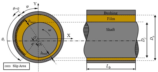
Figure 1.
Schematic diagram of a heterogeneous slip/no-slip journal bearing.
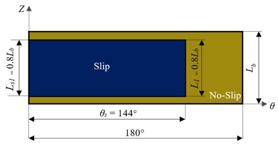
Figure 2.
Configuration of heterogeneous slip/no-slip on stationary surface.

Table 1.
Parameters of the model.
In this study, 10w40 oil was chosen as the non-Newtonian fluid []. Esfe et al. [] revealed that adding Cuo/MWCNT nanoparticles to 10w40 oil will increase the viscosity of the oil and make it shear rate dependent. Here, for calculations, the comparison is made between the 10w40 oil (i.e., Newtonian) and the 10w40+CuO/MWCNT oil (i.e., non-Newtonian). The oil saturation pressure of 10w40 is 13 Pa. The lubricant property used in this work is listed in Table 2.
Table 2.
Parameters of 10w40 oil at temperature of 55 °C [].
2.7. Meshing
The elastohydrodynamic lubrication was considered in this paper. This numerical computation occurs in both the fluid and solid domains. As a result, the meshing procedure is carried out on these two domains. The mesh in the fluid domain is uniform hexahedral. Applying the sweep, edge scaling, and face meshing procedures, the 6 × 356 × 50 mesh is generated in the radial, circumferential, and axial directions, respectively. It results in 106,800 components for the fluid domain. The mesh density for the shaft and bearing in the solid computational domain (shown in Figure 3) is built according to the configuration of the fluid mesh for all directions to achieve conformity and provide a satisfactory coupling setup during the calculations. As a result, the matching grid generated for the solid domain is 185,815 elements. In addition, in this study, the independent grid test is performed to find the most efficient use of the grid while taking the least amount of calculation time. The addition of meshing tests the radial direction, and the number of layers test the radial direction (2, 4, 6, 8, 10). When the number of radial meshing in the layer exceeds 6, the error value does not differ considerably (less than 1 percent). As a result, there are six meshing layers in the radial direction.
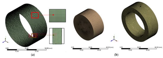
Figure 3.
Mesh of computational (a) fluid domain; (b) solid domain.
2.8. Assumption and Boundary Condition
Figure 4 depicts the fluid and solid computational domains with boundary conditions, with the figures from left to right representing the lubricant domain, shaft domain, and bushing domain, respectively. Two fluid–structure interface pairs link the computational fluid domain and two computational structure domains. The temperature effect is not examined in this work, to simplify computation. The inlet and outlet pressures are adjusted at zero pressure (ambient pressure). The fixed support is utilized for the shaft and bushing sidewalls, while the cylindrical support is used for the outer and inner bushing surfaces, as shown in Figure 4. In this situation, as in real life, the structure is not allowed to move in the axial or circumferential directions, but it is free to move in the radial direction. Table 3 describes the boundary condition employed here.
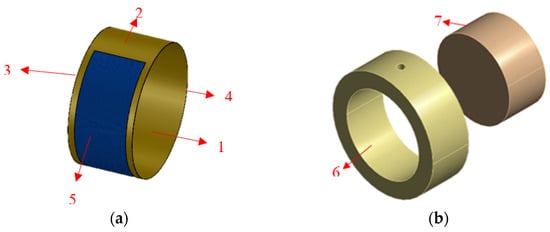
Figure 4.
Boundary condition of computational (a) fluid domain; (b) solid domain; 1—moving wall; 2—stationary wall; 3—inlet; 4—outlet; 5—slip area; 6—contact with stationary wall; 7—contact with moving wall.
Table 3.
Boundary condition.
2.9. Solution Setup
The solution configuration is necessary for CFD in this study. On the pressure–velocity coupling, the SIMPLE computation scheme is utilized. The second-order upwind approach is used to calculate the momentum equation in order to obtain a number that is accurate and easy to converge. The Quadratic Upstream Interpolation for Convective Kinetics (QUICKS) approach is utilized in the momentum building equation to minimize errors in the convection term. The Pressure Staggered Option (PRESTO) is used in the solution setup pressure scheme to produce a good pressure difference prediction. QUICKS and PRESTO are schemes that can speed up the simulation convergence process. For a more accurate result, a convergence tolerance of 1 × 10⁻⁵ (i.e., high resolution) is employed for all residual terms. For the coupling step control, the minimum and maximum iteration steps are 1 and 10, respectively.
3. Results and Discussion
In this study, the flow regime is calculated based on the properties of the flowing fluid referring to the Reynolds number. According to Meng and Zhang [], the flow model becomes entirely turbulent when the real Reynolds number surpasses the value of the critical Reynolds number. The real Reynolds number and the critical Reynolds number are shown, respectively, below.
where Rer = real Reynolds number, Rec = critical Reynolds number; = fluid density; µ = fluid viscosity; ε = eccentricity ratio; ω = rotational speed; c = clearance; and Dj = journal diameter. In all cases considered here, because the Rer is larger than the Rec, then the flow model employed is turbulent, as reflected in Table 4.
Table 4.
Flow model.
It is hypothesized that the application of the heterogeneous slip/no-slip pattern in the journal bearing will result in a significant pressure gradient. As mentioned in the previous section, the realizable k-εt turbulence model was adopted in this study due to additional capabilities. Unlike the standard k-εt turbulence model, the realizable k-εt turbulence model is quite sensitive to the adverse pressure gradient []. As a result, shear stress overestimation can be avoided.
3.1. Validation
To demonstrate that the CFD-FSI approach and its solution configuration can be used for analysis, the results must be correct and within the specified precision. The results of the current study in terms of hydrodynamic pressure distribution are compared with the numerical and experimental data of Dhande and Pande [] as a reference under the same input conditions and computed operational parameters. Figure 5 depicts the comparison of these outcomes. At a rotating speed of 3000 rpm, the present numerical technique yields a maximum hydrodynamic value of 5.504 MPa, or 4 percent lower compared to the result obtained by reference []. In conclusion, the current study’s findings are consistent with those of reference [], implying that the established numerical solution code has been validated. All of the simulations that follow are based on the current code.
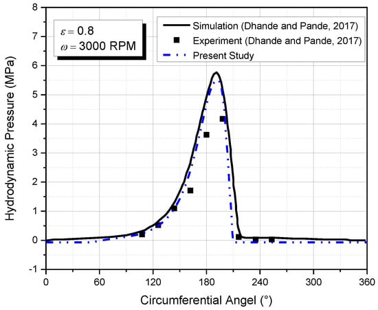
Figure 5.
Comparison of hydrodynamic pressure between the result of the present study and the reference []. The numerical results are evaluated at mid-plane z/L of 0.5, rotational speed of 3000 rpm, and eccentricity ratio ε of 0.8.
3.2. Effect of Non-Newtonian Fluid
In this work, as seen in Table 2, the 10w40 oil is used as a lubricant. Based on experiments conducted by Esfe et al. [], the addition of nanoparticles will affect the viscosity of the 10w40 oil. The parameters used to define non-Newtonian behavior are based on the operating temperature of 55 °C and the addition of 0.05% CuO/MWCNT nanoparticles to 10w40 oil. The effect of this addition is that the oil viscosity of 10w40 becomes shear rate dependent. From the modeling point of view, the viscosity function of the shear rate is known to be a non-Newtonian power law. Under these characteristics, the experiment of Esfe et al. [] obtained m = 0.261 and n = 0.8713, as shown in Table 2.
To evaluate the non-Newtonian effect on the lubrication performance, a liquid viscosity analysis must be conducted. According to Equation (13), the viscosity of a non-Newtonian fluid varies with the shear rate. Figure 6 reflects the dynamic viscosity and shear rate of lubricant for two conditions, namely no-slip and engineered slip in the case of non-Newtonian fluid. From Figure 6, specific features can be drawn. Firstly, both the no-slip (Figure 6a) and engineered slip (Figure 6b) conditions exhibit a substantial shift in viscosity for all cases. The most possible explanation is that in the case of journal bearing, when the eccentricity ratio is applied, the shear rate fluctuates, causing a substantial shift in viscosity, as indicated in Figure 6. Second, as shown in Figure 6b, the viscosity of non-Newtonian fluids is greater under slip conditions than in non-slip situations. Additionally, the increase in viscosity occurs in the slip region of the journal bearing’s convergent zone. The addition of viscosity to the slip area is intended to enhance the fluid pressure distribution. Furthermore, based on Figure 6, it can be shown that the viscosity is inversely proportional to the shear rate, indicating that the greater the shear rate, the smaller the viscosity of the lubricant.
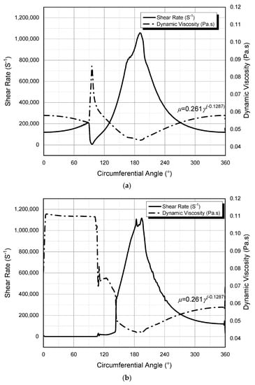
Figure 6.
Shear rate and dynamic viscosity of liquid phase in the case of (a) no-slip; (b) engineered heterogeneous slip/no-slip for bearing lubricated by non-Newtonian fluid. The numerical results are evaluated at mid-plane z/L of 0.5, rotational speed of 4000 rpm, and eccentricity ratio ε of 0.8.
3.3. At Varied Eccentricity Ratio
The eccentricity ratio is shown as the position of the shaft in this investigation. The shaft’s position changes from rest to almost concentric after it receives enough pressure. The weight of the shaft is one of the factors that influence the eccentricity ratio. In the other words, the position of the shaft represents the level of loading. Non-Newtonian fluid lubrication under no-slip and partial slip circumstances, as well as Newtonian fluid lubrication under no-slip and partial slip conditions, are used in this study. To determine the tribological performance of journal bearings, the trends of load-carrying capacity, coefficient of friction, and average acoustic power level are made. The eccentricity ratio is varied to 0, 0.2, 0.4, 0.6, and 0.8, representing the level of loading from concentric condition to high loading situation.
3.3.1. Load-Carrying Capacity
Figure 7 shows the effect of the eccentricity ratio on the load-carrying capacity under different surface and lubricant conditions. Based on Figure 7, some specific characteristics can be drawn. Firstly, the load-carrying capacity increases as the eccentricity of the journal bearing increases. Variations in the flow cross-sectional area of the journal bearing are caused by the widened gap caused by eccentricity. Due to the variation in the cross-sectional area of the fluid flow, the pressure distribution in the fluid flow area of the journal bearing is not uniform. Secondly, as can be seen from Figure 7, at an eccentricity of 0.6, the value of the load-carrying capacity in the case of the Newtonian slip condition is greater than that of the non-Newtonian no-slip one. Meanwhile, at the eccentricity of 0.8, there is a crossing of values which makes the value of the load-carrying capacity of the non-Newtonian no-slip geometry larger than that of the Newtonian partial slip case. The main reason behind this is that the positive effect of slip reduces when the higher eccentric ratio is used, as discussed by several researchers, for example in [,,,]. Thirdly, even with a zero eccentricity, the use of partial slips can generate hydrodynamic pressure. It is well understood that without the use of partial slips, hydrodynamic pressure cannot be generated, and thus the journal bearing cannot be lifted. It prevails both for Newtonian and non-Newtonian cases. Fourth, the load-carrying capacity created by the non-Newtonian fluid at low eccentricity (i.e., ε = 0.2 in this case) has a lower value than that of a Newtonian fluid. Meanwhile, at higher eccentricity ratios (i.e., ε = 0.4; 0.6; 0.8), the bearing lubricated by non-Newtonian fluid always has a higher value of load-carrying capacity. To figure out why the load capacity under non-Newtonian conditions is lower at low eccentricity than under Newtonian conditions, the vapor volume fraction inside the bearing needs to be observed, as depicted in Figure 8. Figure 8 shows in detail how the viscosity that occurs in the slip region increases the value of the negative pressure region, resulting in a higher cavitation value in that area. This is especially true when the eccentricity is low (i.e., ε = 0.2). As shown in Figure 8c,d, the cavitation distribution that occurs in the case of low eccentricity is wider than that in the case of high eccentricity.
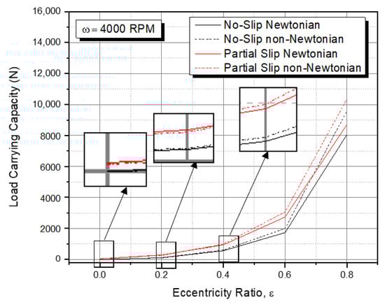
Figure 7.
Load-carrying capacity of journal bearing versus eccentricity ratio for different cases.
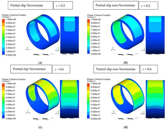
Figure 8.
Vapor volume fraction for partial slip bearing for case: (a) Newtonian, ε = 0.2; (b) non-Newtonian, ε = 0.2; (c) Newtonian, ε = 0.6; (d) non-Newtonian, ε = 0.6.
With respect to the hydrodynamic pressure, Figure 9 shows that the use of non-Newtonian lubricants of the heterogeneous slip/no-slip pattern increases the pressure peak both for the bearing with lower ε and that with higher ε. In addition, from Figure 9, it can be observed that the zone of maximum pressure for the case of the non-Newtonian lubricant is larger than that of Newtonian one. The same pattern holds true when the velocity contour is displayed, as shown in Figure 10. It can be revealed that the non-Newtonian lubricant provides a larger maximum velocity zone in the slip area compared to the Newtonian lubricant for the same eccentricity ratio. With increasing slip velocity, the lubricant rate increases, allowing pressure to rise, and consequently the load-carrying capacity increases. In addition, the numerical results also indicate that the volume flow rate predicted by the non-Newtonian lubricant is around 50% higher than that predicted by the Newtonian lubricant. For example, for ε = 0.6, the volume flow rate of the heterogeneous slip/no-slip pattern lubricated non-Newtonian case is 9.37 × 10⁻⁸ m3/s, while for the Newtonian case, the volume flow rate is just 6.27 × 10⁻⁸ m3/s. These combined effects are able to improve the load-carrying capacity for the non-Newtonian case.
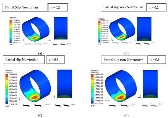
Figure 9.
Pressure distribution for partial slip bearing for case: (a) Newtonian, ε = 0.2; (b) non-Newtonian, ε = 0.2; (c) Newtonian, ε = 0.6; (d) non-Newtonian, ε = 0.6.
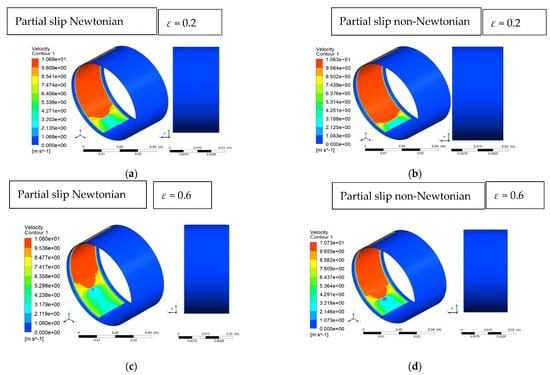
Figure 10.
Velocity distribution for partial slip bearing for case: (a) Newtonian, ε = 0.2; (b) non-Newtonian, ε = 0.2; (c) Newtonian, ε = 0.6; (d) non-Newtonian, ε = 0.6.
Figure 11 depicts the positive effect of partial slip in terms of load-carrying capacity values for several eccentricity ratios for two conditions, i.e., non-Newtonian and Newtonian. It is noted that the value of the load-carrying capacity at zero eccentricity ratio is zero, indicating that hydrodynamic pressure is unable to produce pressure sufficient to lift the shaft. Based on Figure 11, it can be shown that the value of the increase in load-bearing capacity decreases as the eccentricity increases in both Newtonian and non-Newtonian cases. It is interesting to note that the positive effect of the use of the engineered slip is more pronounced for lower eccentricity ratios. Furthermore, under this situation (i.e., lower eccentricity ratios), the use of the non-Newtonian fluid is not superior in comparison to that of a Newtonian fluid. However, for higher eccentricity ratios, non-Newtonian lubricants are recommended to improve load-carrying capacity over Newtonian lubricants. It is understandable because, as mentioned in the previous section, the slip effect goes off when the journal bearing operates in a high eccentricity ratio. In this way, the effect of the non-Newtonian lubricant becomes stronger for improving lubrication performance compared to the slip effect. It is also observed from Figure 11 that employing an engineered slip/no-slip pattern produces the enhancement of the load-carrying capacity by up to 170% and 125%, respectively, for the Newtonian and non-Newtonian fluids.
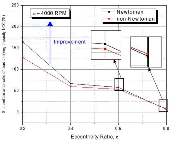
Figure 11.
Slip performance ratio of load-carrying capacity (LCC) for several eccentricity ratios ().
3.3.2. Coefficient of Friction
Figure 12 shows the coefficient of friction for several cases under different eccentricity ratios. The value of the coefficient of friction decreases as the eccentricity of the journal bearing increases. It seems that due to decreased pressure film development, the friction coefficient is greater for bearings with a smaller eccentricity ratio. This is consistent with the findings of Shinde and Soni [], who revealed that the higher the eccentricity ratio, the lower the coefficient of friction produced. Based on Figure 12, it can also be observed that the employment of an engineered heterogeneous slip/no-slip pattern gives a significant decrease in the coefficient of friction irrespective of the used lubricant type. For example, the highest reduction level in the coefficient of friction by up 73% is noted for the case ε = 0.2.
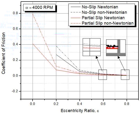
Figure 12.
Coefficient of friction versus eccentricity ratios for different cases.
Regarding the non-Newtonian effect, an interesting feature can be observed based on Figure 12. The simulation results show that non-Newtonian fluid, either combined with slip or not, gives a higher coefficient of friction for all the eccentricity ratios considered here. This finding is in good agreement with the reference [,]. In the study of Kalada et al. [], the addition of CuO nanoparticles to 15w40 base oil in journal bearings indicated that the lubricant became non-Newtonian and resulted in an increase in load-carrying capacity and an increase in the friction coefficient. It was also demonstrated in the experiment by Shinde and Soni [] that the addition of CuO nanoparticles to 30 SAE oil created similar behavior (i.e., the increased coefficient of friction).
3.3.3. Acoustic Power Level
In this section, the bearing noise in terms of average acoustic power level is studied for several conditions. Figure 13 shows the comparison of the average acoustic power level varying the eccentricity ratios. Some interesting features can be drawn from Figure 13. First, when the eccentricity of the journal bearing increases, the average acoustic power level also increases. This finding matches well with the work of Meng et al. [,]. Second, the average acoustic power level for non-Newtonian fluids is always higher than that for Newtonian fluids. It is understandable because the viscosity of a non-Newtonian fluid tends to be higher in most of the bearing area than that of a Newtonian fluid. As a result, when the viscosity of the fluid increases, the average acoustic power level can increase. Furthermore, to investigate the non-Newtonian effect, it is necessary to explore the turbulence indicator inside the bearing leading to the noise, that is, turbulence kinetic energy. In fluid dynamics, turbulence kinetic energy is the mean kinetic energy per unit mass associated with eddies in a turbulent flow. As shown in Figure 14, the maximum turbulence kinetic energy for the case of the non-Newtonian lubricant is higher in comparison to the Newnan case. Third, the notable finding here is that the use of engineered partial slip in bearings reduces the bearing noise significantly. The reduction in the average acoustic power level ranges from 20 to 28% depending on the eccentricity ratio of the journal, irreversible of the used lubricant type (i.e., Newtonian or non-Newtonian).
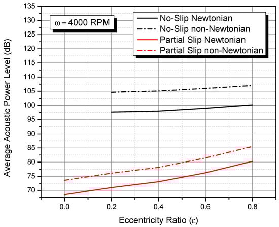
Figure 13.
Average acoustic power level of journal bearing for several cases varying the eccentricity ratios.
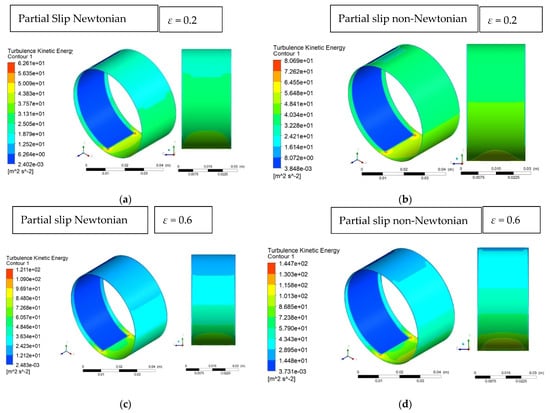
Figure 14.
Turbulence kinetic energy for partial slip bearing for case: (a) Newtonian, ε = 0.2; (b) non-Newtonian, ε = 0.2; (c) Newtonian, ε = 0.6; (d) non-Newtonian, ε = 0.6.
Regarding the effect of the non-Newtonian fluid, it is necessary to directly compare the performance of the average acoustic power level for two conditions, i.e., Newtonian and non-Newtonian. Here, the comparison is made by introducing the slip performance ratio of the average acoustic power level. Figure 15 shows the beneficial effect of engineered slip for two conditions, i.e., Newtonian and non-Newtonian, in terms of average acoustic power level. Based on Figure 15, it is found that the difference in the performance ratio of the average acoustic power level between Newtonian and non-Newtonian cases increases with increasing the eccentricity ratio. For example, for ε = 0, the performance ratio in the case of Newtonian fluid is around 28.7%, while for non-Newtonian fluid, the performance ratio is just 28.4% (or 0.3% higher). When the eccentricity ratio is increased to, say, 0.8, the non-Newtonian lubricant gives a lower average acoustic power level. It indicates that when engineered partial slip is combined with non-Newtonian fluid, the reduced bearing noise is observed even though it is not so significant: it is just around a 1% improvement.
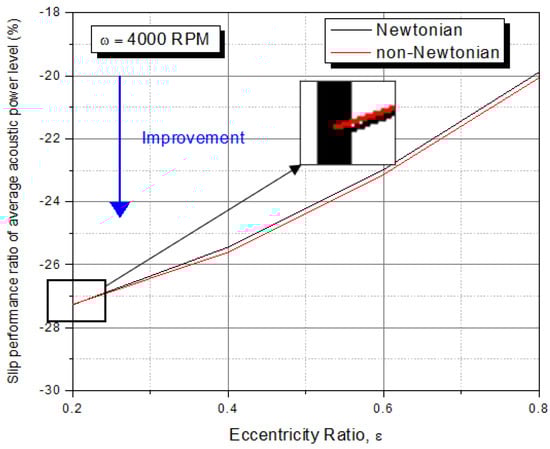
Figure 15.
Slip performance ratio of average acoustic power level PA for several eccentricity ratios for the case of Newtonian and non-Newtonian fluids ). The negative sign indicates a performance improvement.
4. Conclusions
Through CFD and FSI procedures, the paper presented a detailed study of the lubrication performance indices of lubricated journal bearings with engineered heterogeneous slip/no-slip patterns lubricated by a non-Newtonian fluid. The fluid cavitation phenomenon was modeled using a multiphase change boundary condition. The effects of slip and non-Newtonian variation on eccentricity ratios were quantified here. Based on the elastohydrodynamic analysis, the results for the non-Newtonian bearing with or without slip were compared to the classical bearing lubricated by Newtonian fluids. The following are the main findings of the current study:
- The CFD and FSI procedures are demonstrated to be useful tools for predicting elastohydrodynamic (EHD) simulation of heterogeneous slip/no-slip journal bearings.
- The engineered heterogeneous slip/no-slip pattern produces the improvement of the bearing performance (i.e., increased load-carrying capacity by up to 170%, reduced coefficient of friction by up to 73%, and decreased noise by up to 28%), irrespective of the lubricant type used. The highest performance of the engineered heterogeneous slip/no-slip journal bearing can be attained when the eccentricity ratio is the lowest.
- For improving tribological performance (i.e., load-carrying capacity and coefficient of friction), the use of a Newtonian lubricant is preferable, whereas non-Newtonian fluid is recommended for lowering bearing noise.
Because of the complexities of the effect of slip boundary on journal bearings, the current model simplifies by ignoring the thermal deformation of the structure and assuming the lubricant is in an isothermal state. As a result, more analyses involving the viscosity–temperature dependency as well as the conjugate heat transfer will be required and addressed in future work to obtain a more realistic lubrication condition in the study of heterogeneous slip/no-slip bearings. Experiments on the use of the heterogeneous slip/no-slip pattern for assessing acoustic performance must also be carried out.
Author Contributions
Conceptualization, M.T.; methodology, M.T.; software, B.S. and M.I.A.; validation, B.S.; formal analysis, S.S. and C.P.; investigation, A.H.P.; resources, M.T. and J.J.; data curation, C.P.; writing—original draft preparation, M.T. and A.H.P.; writing—review and editing, S.S. and C.P; visualization, B.S. and A.H.P.; supervision, J.J.; project administration, M.I.A.; funding acquisition, J.J. and M.T. All authors have read and agreed to the published version of the manuscript.
Funding
This research is fully funded by Universitas Diponegoro through WCRU Grant No. 118-13/UN7.6.1/PP/2021 (second year).
Institutional Review Board Statement
Not applicable.
Informed Consent Statement
Not applicable.
Data Availability Statement
The data presented in this study are available on request from the corresponding author.
Acknowledgments
The authors fully acknowledged Institute for Research and Community Services (LPPM), Diponegoro University, for the approved fund which makes this important research viable and effective.
Conflicts of Interest
The authors declare no conflict of interest.
References
- Barrat, J.-L.; Bocquet, L. Large slip effect at a nonwetting fluid-solid interface. Phys. Rev. Lett. 1999, 82, 4671–4674. [Google Scholar] [CrossRef]
- Barrat, J.-L.; Bocquet, L. Influence of wetting properties on hydrodynamic boundary conditions at a fluid/solid interface. Faraday Discuss. 1999, 112, 119–128. [Google Scholar] [CrossRef] [Green Version]
- Baudry, J.; Charlaix, E.; Tonck, A.; Mazuyer, D. Experimental evidence for a large slip effect at a nonwetting fluid-solid interface. Langmuir 2001, 17, 5232–5236. [Google Scholar] [CrossRef]
- Spikes, H.A. The Half-wetted bearing. Part 2: Potential application in low load contacts. Proc. Inst. Mech. Eng. Part J J. Eng. Tribol. 2003, 217, 15–26. [Google Scholar] [CrossRef]
- Wilson, M.C.T.; Summers, J.L.; Shikhmurzaev, Y.D.; Clarke, A.; Blake, T.D. Non local hydrodynamic influence on the dynamic contact angle: Slip models versus experiment. Phys. Rev. E 2006, 73, 041606. [Google Scholar] [CrossRef] [Green Version]
- Blake, T.D.; Fernandez-Toledano, J.C.; Doyen, G.; de Coninck, J. Forced wetting and hydrodynamic assist. Phys. Fluids 2015, 27, 112101. [Google Scholar] [CrossRef]
- Ma, G.J.; Wu, C.W.; Zhou, P. Wall Slip and hydrodynamics of two-dimensional journal bearing. Tribol. Int. 2007, 40, 1056–1066. [Google Scholar] [CrossRef]
- Bhattacharya, A.; Dutt, J.K.; Pandey, R.K. Influence of hydrodynamic journal bearings with multiple slip zones on rotordynamic behavior. J. Tribol. 2017, 139, 405–413. [Google Scholar] [CrossRef]
- Rao, T.V.V.L.N.; Rani, A.M.A.; Awang, M.; Hashim, F.M. Stability evaluation of three-layered journal bearing with slip/partial slip. Ind. Lubr. Tribol. 2017, 69, 334–341. [Google Scholar] [CrossRef]
- Wu, C. Performance of hydrodynamic lubrication journal bearing with a slippage surface. Ind. Lubr. Tribol. 2008, 60, 293–298. [Google Scholar] [CrossRef]
- Tauviqirrahman, M.; Afif, M.F.; Paryanto, P.; Jamari, J.; Caesarendra, W. Investigation of the tribological performance of heterogeneous slip/no-slip journal bearing considering thermo-hydrodynamic effects. Fluids 2021, 6, 48. [Google Scholar] [CrossRef]
- Zhang, H.; Hua, M.; Dong, G.; Zhang, D.; Chin, K.-S. Boundary Slip Surface Design for High Speed Water Lubricated Journal Bearings. Tribol. Int. 2014, 79, 32–41. [Google Scholar] [CrossRef]
- Lin, Q.; Wei, Z.; Zhang, Y.; Wang, N. Effects of the slip surface on the tribological performances of high-speed hybrid journal bearings. Proc. Inst. Mech. Eng. Part J J. Eng. Tribol. 2016, 230, 1149–1156. [Google Scholar] [CrossRef]
- Cui, S.; Zhang, C.; Fillon, M.; Gu, L. Optimization performance of plain journal bearings with partial wall slip. Tribol. Int. 2020, 145, 106137. [Google Scholar] [CrossRef]
- Li, W.-L.; Chu, H.-M.; Chen, M.-D. The partially wetted bearing—Extended Reynolds equation. Tribol. Int. 2006, 39, 1428–1435. [Google Scholar] [CrossRef]
- Singh, J.P.; Ahmad, N. Analysis of a porous-inclined slider bearing lubricated with magnetic fluid considering thermal effects with slip velocity. J. Braz. Soc. Mech. Sci. Eng. 2011, 33, 351–356. [Google Scholar] [CrossRef]
- Pratomo, A.W.; Muchammad, M.; Tauviqirrahman, M.; Jamari, J.; Bayuseno, A. Numerical investigation of pocketed slip slider bearing with non-Newtonian lubricant. Tribol. Mater. Surf. Interfaces 2016, 10, 64–69. [Google Scholar] [CrossRef]
- Pratomo, A.W.; Muhammad; Tauviqirrahman, M.; Jamari, J.; Bayuseno, A.P. Analysis of non-Newtonian lubricated textured contact for mixed slip/no-slip configuration considering cavitation. J. Phys. Conf. Ser. 2019, 1217, 012014. [Google Scholar] [CrossRef]
- Rao, T.V.V.L.N.; Rani, A.M.A.; Nagarajan, T.; Hashim, F.M. Analysis of micropolar and power law fluid–lubricated slider and journal bearing with partial slip–partial slip texture configuration. Tribol. Trans. 2016, 59, 896–910. [Google Scholar] [CrossRef]
- Lin, Q.; Wei, Z.; Wang, N.; Chen, W. Effect of large-area texture/slip surface on journal bearing considering cavitation. Ind. Lubr. Tribol. 2015, 67, 216–226. [Google Scholar] [CrossRef]
- Senatore, A.; Rao, T.V.V.L.N. Partial slip texture slider and journal bearing lubricated with Newtonian fluids: A review. J. Tribol. 2018, 140, 040801. [Google Scholar] [CrossRef]
- Gertzos, K.P.; Nikolakopoulos, P.G.; Papadopoulos, C.A. CFD analysis of journal bearing hydrodynamic lubrication by bingham lubricant. Tribol. Int. 2008, 41, 1190–1204. [Google Scholar] [CrossRef]
- Patlazhan, S.; Vagner, S. Apparent slip of shear thinning fluid in a microchannel with a superhydrophobic wall. Phys. Rev. E 2017, 96, 013104. [Google Scholar] [CrossRef] [PubMed]
- Kumar, R.; Azam, M.S.; Ghosh, S.K.; Khan, H. Effect of surface roughness and deformation on Rayleigh step bearing under thin film lubrication. Ind. Lubr. Tribol. 2017, 69, 1016–1032. [Google Scholar] [CrossRef]
- Vladescu, S.C.; Marx, N.; Fernandez, L.; Barcelo, F.; Spikes, H. Hydrodynamic friction of viscosity-modified oils in a journal bearing machine. Tribol. Lett. 2018, 66, 127. [Google Scholar] [CrossRef] [Green Version]
- Bhattacharjee, R.C.; Das, N.C. Power law fluid model incorporated into elastohydrodynamic lubrication theory of line contact. Tribol. Int. 1996, 29, 405–413. [Google Scholar] [CrossRef]
- Khatri, C.B.; Sharma, S.C. Influence of textured surface on the performance of non-recessed hybrid journal bearing operating with non-Newtonian lubricant. Tribol. Int. 2016, 95, 221–235. [Google Scholar] [CrossRef]
- Hauswirth, S.C.; Bowers, C.A.; Fowler, C.P.; Schultz, P.B.; Hauswirth, A.D.; Weigand, T.; Miller, C.T. Modeling cross model non-newtonian fluid flow in porous media. J. Contam. Hydrol. 2020, 235, 103708. [Google Scholar] [CrossRef]
- Wang, Y.; Wu, J.H.; Xu, L. Influence of power-law fluid on transient performance of liquid film seal based on the time-dependent non-Newtonian dynamic Reynolds equation. Tribol. Int. 2021, 159, 106984. [Google Scholar] [CrossRef]
- Pereira, B.M.M.; Dias, G.A.S.; Cal, F.S.; Rajagopal, K.R.; Videman, J.H. Lubrication approximation for Fluids with Shear-Dependent Viscosity. Fluids 2019, 4, 98. [Google Scholar] [CrossRef] [Green Version]
- Dang, R.K.; Goyal, D.; Chauhan, A.; Dhami, S.S. Effect of non-newtonian lubricants on static and dynamic characteristics of journal bearings. Mater. Today Proc. 2020, 28, 1345–1349. [Google Scholar] [CrossRef]
- Tomar, A.K.; Sharma, S.C. Non-Newtonian lubrication of hybrid multi-recess spherical journal bearings with different geometric shapes of recess. Tribol. Int. 2022, 171, 107579. [Google Scholar] [CrossRef]
- Dhande, D.Y.; Pande, D.W. A two-way FSI analysis of multiphase flow in hydrodynamic journal bearing with cavitation. J. Braz. Soc. Mech. Sci. Eng. 2017, 39, 3399–3412. [Google Scholar] [CrossRef]
- Chetti, B.; Zouggar, H. Steady-state performance of a circular journal bearing lubricated with a non-Newtonian fluid considering the elastic deformation of the liner. Proc. Inst. Mech. Eng. Part J J. Tribol. 2019, 233, 1389–1396. [Google Scholar] [CrossRef]
- Liang, X.; Yan, X.; Liu, Z.; Ouyang, W. Effect of perturbation amplitudes on water film stiffness coefficients of water-lubricated plain journal bearings based on CFD–FSI methods. Proc. Inst. Mech. Eng. Part J J. Tribol. 2019, 233, 1003–1015. [Google Scholar] [CrossRef]
- Tauviqirrahman, M.; Jamari, J.; Bagir, M.; Caesarendra, W.; Paryanto, P. Elastohydrodynamic behavior analysis on water-lubricated journal bearing: A study of acoustic and tribological performance based on CFD-FSI approach. J. Braz. Soc. Mech. Sci. Eng. 2022, 44, 1. [Google Scholar] [CrossRef]
- Frêne, J.; Arghir, M.; Constantinescu, V. Combined thin-film and Navier–Stokes analysis in high Reynolds number lubrication. Tribol. Int. 2006, 39, 734–747. [Google Scholar] [CrossRef]
- Proudman, I. The Generation of noise by isotropic turbulence. Proc. R. Soc. Lond. Ser. A Math. Phys. Sci. 1952, 214, 119–132. [Google Scholar] [CrossRef]
- Meng, F.M.; Zhang, W. Effects of compound groove texture on noise of journal bearing. J. Tribol. 2018, 140, 031703. [Google Scholar] [CrossRef]
- Meng, F.; Yu, H.; Gui, C.; Chen, L. Experimental study of compound texture effect on acoustic performance for lubricated textured surfaces. Tribol. Int. 2019, 133, 47–54. [Google Scholar] [CrossRef]
- ANSYS Fluent. User Manual, Version 16.0; ANSYS Inc.: Canonsburg, PA, USA, 2017. [Google Scholar]
- Zwart, P.J.; Gerber, A.G.; Belamri, T. A two-phase flow model for predicting cavitation dynamics. In Proceedings of the International Conference on Multiphase Flow, Yokohama, Japan, 30 May–3 June 2004; p. 152. [Google Scholar]
- Neto, C.; Evans, D.R.; Bonaccurso, E. Boundary slip in Newtonian liquids: A review of experimental studies. Rep. Prog. Phys. 2005, 68, 2859. [Google Scholar] [CrossRef]
- Spikes, H.; Granick, S. Equation for slip of simple liquids at smooth solid surfaces. Langmuir 2003, 19, 5065–5071. [Google Scholar] [CrossRef]
- Choo, J.H.; Glovnea, R.P.; Forrest, A.K.; Spikes, H.A. A low friction bearing based on liquid slip at the wall. ASME J. Tribol. 2007, 129, 611–620. [Google Scholar] [CrossRef]
- Tauviqirrahman, M.; Pratama, A.; Jamari, J.; Muchammad, M. Hydrodynamic lubrication of textured journal bearing considering slippage: Two-dimensional CFD analysis using multiphase cavitation model. Tribol. Ind. 2019, 41, 401–415. [Google Scholar] [CrossRef]
- Esfe, M.H.; Zabihi, F.; Rostamian, H.; Esfandeh, S. Experimental investigation and model development of the non-Newtonian behavior of CuO-MWCNT-10w40 hybrid nano-lubricant for lubrication purposes. J. Mol. Liq. 2018, 249, 677–687. [Google Scholar] [CrossRef]
- Shinde, V.; Soni, S. Effect of lubricants with nanoparticles on performance of hydrodynamic journal bearing. In Proceedings of the TRIBOINDIA-2018 an International Conference on Tribology, Mumbai, India, 13–15 December 2018. [Google Scholar] [CrossRef]
- Kalakada, S.B.; Kumarapillai, P.N.N.; Rajendra Kumar, P.K. Static characteristics of thermohydrodynamic journal bearing operating under lubricants containing nanoparticles. Ind. Lub. Tribol. 2015, 67, 38–46. [Google Scholar] [CrossRef]
Publisher’s Note: MDPI stays neutral with regard to jurisdictional claims in published maps and institutional affiliations. |
© 2022 by the authors. Licensee MDPI, Basel, Switzerland. This article is an open access article distributed under the terms and conditions of the Creative Commons Attribution (CC BY) license (https://creativecommons.org/licenses/by/4.0/).