Article

Model Assessment of an Open-Source Smoothed Particle Hydrodynamics (SPH) Simulation of a Vibration-Assisted Drilling Process

1
Department of Process Engineering, Leibniz Institute for Materials Engineering—IWT, 28359 Bremen, Germany
2
Department of Particles and Process Engineering, University of Bremen, 28359 Bremen, Germany
*
Author to whom correspondence should be addressed.
Fluids 2022, 7(6), 189; https://doi.org/10.3390/fluids7060189
Submission received: 30 March 2022 / Revised: 25 May 2022 / Accepted: 27 May 2022 / Published: 29 May 2022

Abstract

:
Minimum Quantity Lubrication (MQL) is a cooling and lubrication variant applied, for instance, in drilling processes. In the present approach, a new vibration-assisted drilling process is analyzed, which has considerable potential for manufacturing of extremely hard materials. Within this process, the MQL gas/liquid transport in the presence of a vibrating and rotating twist drill bit in the borehole is to be studied. Multiphase computational fluid dynamics is applied to analyze and optimize the MQL flow. However, applying conventional CFD methods with discretized continuum equations on a numerical grid is challenging in this process, as the vibrating drill bit frequently closes the gap in the borehole, where even dynamic grid application fails. The ability to use an open-source Smoothed Particle Hydrodynamics (SPH) meshless method to analyze the lubrication media flow is carried out to accurately and efficiently address this problem and overcome the severe limitations of conventional mesh-based methods. For a feasibility study of the method, the MQL air phase in the dynamic drill cavity is analyzed by SPH and validated against conventional CFD method results. The present study shows insufficient results of the SPH method, both in terms of solution plausibility and computational cost, for simulation of the problem at hand.

1. Introduction

Vibration-assisted drilling is a variant of the conventional drilling process for metals in which the twist drill bit has both a rotational and an axial vibrational movement. The addition of an axial vibrational movement in comparison to pure rotating standard drilling has a significant impact on the machinability of difficult-to-cut materials due to the profound difference in the chip formation process. Conventional drilling typically produces long spiral chips, whereas the axial vibration of vibration-assisted drilling determines a periodic breaking up of the forming chip. Therefore, this results in many small chips. The ultimate effects connected to this different machining process are: a lower thermo-mechanical load of the tool, more uniform bore dimensions, and a higher bore surface quality. From these premises, the importance of this technology clearly emerges for improving the effectiveness in machining materials such as Inconel and Titanium, but also Aluminum [1].
Similar to conventional drilling, the vibration-assisted drilling process has to be lubricated and cooled down by delivering Metalworking Fluid (MWF) to the cutting zone. This can be achieved in two different ways: (i) via one or multiple external nozzles or (ii) via internal helical channels [2,3,4]. In this study, the attention has been focused on the internal lubrication/cooling system.
Oil-based liquids have represented the standard choice for cutting fluids. However, more recently, a novel way of lubricating/cooling machining processes has emerged, namely Minimum Quantity Lubrication (MQL). This novel technique presents economic, ecological, and safety advantages [5]. The cutting fluid in MQL is a mixture of air and oil. More precisely, only the strictly necessary amount of oil is added to the air flow to reduce oil consumption while still ensuring adequate lubrication/cooling. Typical oil flow rates for drilling processes using MQL range from 10 mL/h to 200 mL/h [2].
The combination of vibration-assisted drilling and Minimum Quantity Lubrication represents, therefore, a significant improvement in drilling performance. Nonetheless, a detailed investigation of MWF flow in the case of a vibrating drill bit has not been carried out yet. This analysis is particularly important since it can highlight possible optimal operating conditions for relevant parameters, e.g., oil flow rate and air flow rate. The experimental investigation is limited by the difficulty of detecting local flow conditions in narrow gaps and is often restricted to the analysis of non-vibrating free drill bits, i.e., drill bits not in boreholes [3,6,7,8,9]. On the contrary, numerical investigation can overcome this limitation. However, the vibrational movement of the drill bit poses severe challenges to the numerical techniques. Conventional mesh-based techniques are not well suited for dealing with this problem because they require a continuous, complex, and very demanding dynamic meshing and/or re-meshing procedure during the simulation.
A valid alternative to standard numerical techniques is represented by the class of so-called mesh-less or mesh-free methods. Among them, one of the most well-established methods is Smoothed Particle Hydrodynamics (SPH) [10,11,12]. In contrast to mesh-based techniques, SPH offers greater flexibility, as they are not constrained to generate any grid. This task can be difficult and very time-consuming for complex and specifically temporal varying geometries, as in the case of vibrating drill bits. Furthermore, the Lagrangian nature of the method provides a natural adaptation to topology changes and boundary displacements. This feature makes SPH particularly suitable for the simulation of vibration-assisted drilling processes. On the other hand, SPH suffers from some critical aspects. First, enforcement of boundary conditions is not as straightforward as for mesh-based methods, and special measures have to be adopted for this scope. Second, variable resolution cannot be achieved in a simple way. This aspect is of particular importance if large solution gradients are to be accurately solved. Third, the computational cost might be significantly higher than for mesh-based methods. However, this last point applies mainly to problems with static boundaries, SPH not being subject to significant computational overhead due to moving boundaries. Therefore, this issue might not represent a disadvantage concerning mesh-based methods for the problem at hand. Nonetheless, the significant intrinsic computational cost requires appropriate parallelization techniques. In particular, the highly-parallelizable SPH algorithms make the method well suited for Graphics Processing Unit (GPU) computing.
Several studies have been developed using different approaches to the SPH method in the recent past. Fourtakas et al. [13,14] applied the SPH method to investigate the multiphase flow of sediment resuspension in industrial tanks. Aureli et al. [15] analyzed the dam-break flood and compared the results obtained with mesh-based solvers and the SPH method. Hosain et al. [16] implemented a heat transfer model to the SPH method in order to investigate different benchmark cases and compared the obtained results with Finite-Volume method (FVM) simulations. Raizah et al. [17] investigated the thermosolutal convection of a nanofluid inside an annulus with different cavities. Most of the investigations using the SPH method have been dedicated to analyzing the formation of waves and their interaction with different structures in maritime engineering [18,19,20,21,22,23,24,25,26,27,28,29,30,31] and sloshing tanks [32,33]. Manenti et al. [34] presented an overview of SPH applications related to natural hazards connected to rapidly varied flows of water and dense granular mixtures. SPH has already been employed to simulate MWF flow in drilling processes [35,36,37]. However, these studies were limited to non-vibrating drilling and without utilization of MQL. In the present work, the suitability of SPH to deal with coolant/lubricant flow for vibration-assisted drilling processes has been investigated. The challenge of the simulation is the numerical description of the topological change in the flow geometry with a complete closing of the cavity in the vibrating orifice closure. No validation of this specific arrangement can be achieved. However, validation of the code is carried out, and a list of validated cases for the DualSPHysics solver, for instance, for free surface or oscillating flows, is given on the DualSPHysics website at: https://dual.sphysics.org/old-site/index.php/validation/ (accessed on 13 May 2022).
The manuscript describes a feasibility study of the SPH method to analyze a complex flow field in a variable domain, including topological changes (complete closing of the gap between the drill bit and bore ground). Grid-based CFD methods are not suitable for this kind of flow regime. The SPH results aim to show the principal ability of the method to describe the flow. No physical discussion is intended at the present state of the application of SPH to the process. As a first approach to the problem, a single-phase flow consisting of pure air has been addressed, neglecting the presence of the oil phase. Simulations have been carried out employing the open-source SPH code DualSPHysics [38].
The following section presents the numerical setup and the basic mathematical approach of the SPH method. Then, the simulation results of two different cases are presented. In the former, a benchmark case with static boundaries is shown. In this study, SPH is compared to standard mesh-based FVM results obtained by the commercial code Ansys Fluent v19.2. In the latter section, SPH is applied to the case of the vibrating twist drill bit in order to assess the ability of the method concerning the application at hand.

2. Numerical Setup

2.1. SPH Discretization

In SPH, the fluid domain is split into a set of elements, referred to as particles. Each particle represents a portion of the fluid domain and it carries over different quantities, e.g., volume, mass, density, and velocity. The interaction between particles is mediated by a kernel function, which determines the smoothing of the particles and their related physical quantities over a certain region around their locations. Therefore, the value of a specific quantity at a certain point of space can be obtained by a weighted summation of the values of all the particles that lie within the kernel radius around this point, as expressed by the following equation:
f ( x ) = b f ( x b ) m b ρ b W ( x x b )  
where f represents a generic quantity, m b and ρ b are, respectively, the mass and density of an SPH particle within the kernel radius, and W denotes the kernel function. The kernel W is a function of the distance vector between the point of interest and the SPH particle position x b and it determines the strength of the different weighting factors associated with each SPH particle in the summation. Typical kernel functions are Gaussian and Wendland functions [39]. The latter presents the advantage of a compact support. For a detailed introduction to SPH approximation and the different properties of kernel functions, the reader is referred to [12,40].
Starting from the SPH discretized convolution integral, it is possible to derive a set of discretized evolution equations for each particle from the fluid governing equations. The discretized continuity equations for a generic particle denoted by the subscript “ a ” reads:
d ρ a d t = ρ a b m b ρ b ( V a V b ) a W ( x a x b )  
where V represents the velocity vector and a is the gradient operator applied to the kernel function with respect to its first variable. The discretized momentum equation is:
d V a d t = b m b ( p b + p a ρ b ρ a + Π a b ) a W ( x a x b ) + g  
where p denotes the pressure, g is the gravity vector and Π a b is an artificial viscosity stabilization term proposed by Monaghan [12].
The SPH solver implemented in DualSPHysics is based on the so-called Weakly Compressible SPH (WCSPH) approach. This approach is specifically for incompressible flows. Compressible SPH formulations can be mostly found in software packages for astrophysical applications. However, SPH codes for engineering applications rely almost exclusively on incompressible formulations. Since pressure and, accordingly, density variations across the simulation domain considered in the present study and described in the next section are not relevant, an incompressible approach is suitable to compute accurately the single-phase flow under investigation.
In order to circumvent the demanding solution of a global Poisson equation for the pressure which would be required for an incompressible approach, WCSPH enforces the incompressibility through the following equation of state, known as the Cole equation:
p = b [ ( ρ ρ 0 ) γ 1 ]
with b = c 0 2 ρ 0 / γ . The quantity ρ 0 is a reference density, c 0 is the speed of sound at the reference density, and γ is the specific heat ratio. In WCSPH c 0 is given an artificial value. In order to guarantee small density variations, the artificial speed of sound has to be taken at least 10 times larger than the maximum fluid velocity in the domain [41]. This can result in a significant time-step limitation in high-speed flows due to a large value of the artificial speed of sound. Nonetheless, in most cases, this issue does not cancel out the benefit of not having a global Poisson equation for a large number of particles. Time-integration of SPH discretized equations allows the values of position, velocity and density (pressure) of the particles to be computed at each time step. Various integration schemes can be used for this purpose. In the present study, a symplectic scheme, as implemented in DualSPHysics, has been used. The Dynamic Boundary Condition [42] method implemented in DualSPHysics has been adopted to treat solid boundaries.

2.2. Numerical Details and Operating Conditions

A sketch of the drill bit geometry under investigation is presented in Figure 1. Numerical simulations are performed using only the tip of the drill bit, as presented in Figure 1b. The fluid domain of this geometry consists of three parts: the final portion of the internal channels, the cutting zone, and the flutes. The twist drill bit diameter is 5 mm, whereas the domain length along the x-direction is ~8 mm. The gap between the drill bit tip and the borehole bottom is 120 μm, corresponding to the average distance during the oscillation of the vibration-assisted drilling process. The internal channel diameter is equal to 700 μm.
The rotational movement of the drill bit is not considered. A single-phase of pure air was considered with an inlet velocity of 100 m/s and atmospheric pressure at the outlet section of the flutes. The no-slip condition has been enforced at the walls. Physical properties of air at room temperature have been used. The main geometric dimensions and operating conditions are summarized in Table 1.
The comparison between the open-source SPH code DualSPHysics and the commercial FVM code Ansys Fluent has been performed on a test case with the geometry of Figure 2. The FVM simulation has been performed using one of the steady-state pressure-based solvers available in Ansys Fluent, namely the coupled solver. Second-order discretization schemes and appropriate relaxation factors have been employed. Flow compressibility has been accounted for as well as turbulence using the Reynolds-averaged k-ω SST turbulence model. In detail, a turbulent intensity of 5% has been assumed at the domain inlet, whereas the corresponding condition for ω has been obtained by prescribing a turbulent length scale of 4.9 × 10⁻⁵, equal to 7% of the internal channel diameter. The FVM simulation has been performed using a numerical grid consisting of about 2.4 million elements in order to have a number of elements comparable to the number of particles of the SPH simulation, as described further below in this section.
In order to stabilize the numerical procedure, the artificial viscosity stabilization technique provided by DualSPHysics has been enabled. For the same reason, a ramp for the inlet velocity has been adopted. A combination of boundary and initial conditions that gives rise to initial very steep local gradients of the velocity field might cause stability problems. In the current case, without any measurement the velocity would change from the inlet boundary value of 100 m/s to the internal initial value of 0 m/s. A different initialization of the internal field is not a trivial task. Therefore, the most straightforward way to cope with this issue is achieved by letting the inlet velocity value smoothly increase. In detail, an initial inlet velocity of 1 m/s has been fixed, which rises to 100 m/s over a time period of 0.04 s.

3. Results and Discussion

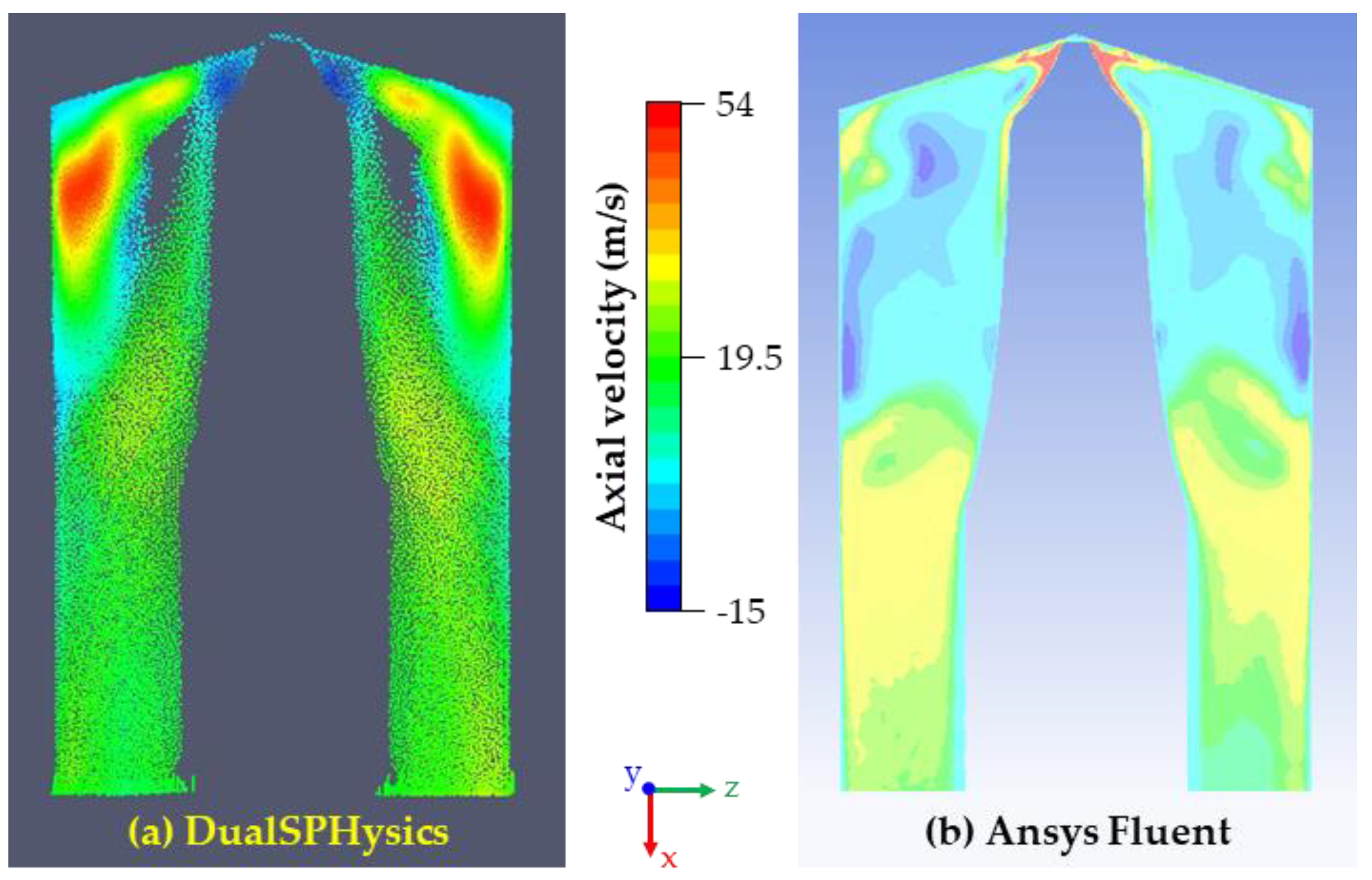
3.1. Benchmark Case with Static Drill Bit

The current section reports the comparison between the open-source SPH code DualSPHysics and the commercial FVM code Ansys Fluent. A resolution of 30 μm has been chosen for the SPH simulation, resulting in an overall number of particles of about 2.6 million. This allows a more meaningful comparison with the results from Ansys Fluent, since the resulting number of SPH particles is comparable to the number of elements of the FVM simulation. A time-marching simulation of 0.05 physical time has been carried out with a Courant number of 0.2. Nearly steady-state results were obtained at the end of the simulation, which required about 10 days of GPU computing. A finer SPH particle resolution would have resulted in a prohibitive computational cost. Figure 3 compares the results obtained by the open-source SPH code DualSPHysics and the commercial code Ansys Fluent, respectively, on a longitudinal section cutting the flutes.
Although SPH is able to capture the regions of recirculating flow, some qualitative and quantitative differences with respect to the FVM results emerge from this comparison. First, the extension of the recirculating regions is significantly smaller in the SPH simulation. These recirculations correspond to the void portions of the fluid domain not occupied by the particles. As it uses the Lagrangian method, the particles tend to flow past the recirculations and not get trapped in them. Compared to Ansys Fluent results, these regions affect a smaller part of the flute cross-section and extend less downstream along the x-direction. From a quantitative point of view, an inspection of the color scales of both the plots indicates the relevant difference regarding the maximum velocity. The SPH simulation is not able to capture the velocity peak located in the narrow gap where the drill bit and borehole bottom are close to each other. This fact can be motivated by the lower local resolution used for the SPH simulation. The impossibility of adopting a variable resolution poses a restriction on the capability of capturing large solution gradients. Another factor, which could play a critical role regarding the solution accuracy, is represented by the turbulence model. While rigorous turbulence modelling is well established for FVM simulations (and, in general, for all mesh-based methods), the treatment of the turbulence is not equally developed in the SPH framework. Though a direct quantitative comparison between the SPH and FVM results has not been derived, and as, of course, the FVM results may be inaccurate to some extent, it still seems that, especially due to the missing particles in the recirculation regions in the SPH simulation results, the qualitative behavior of the SPH solution appears less plausible. Thus, the present study shows some degree of unsatisfactory results of the SPH method both in terms of solution plausibility and computational cost for simulating the problem in question.

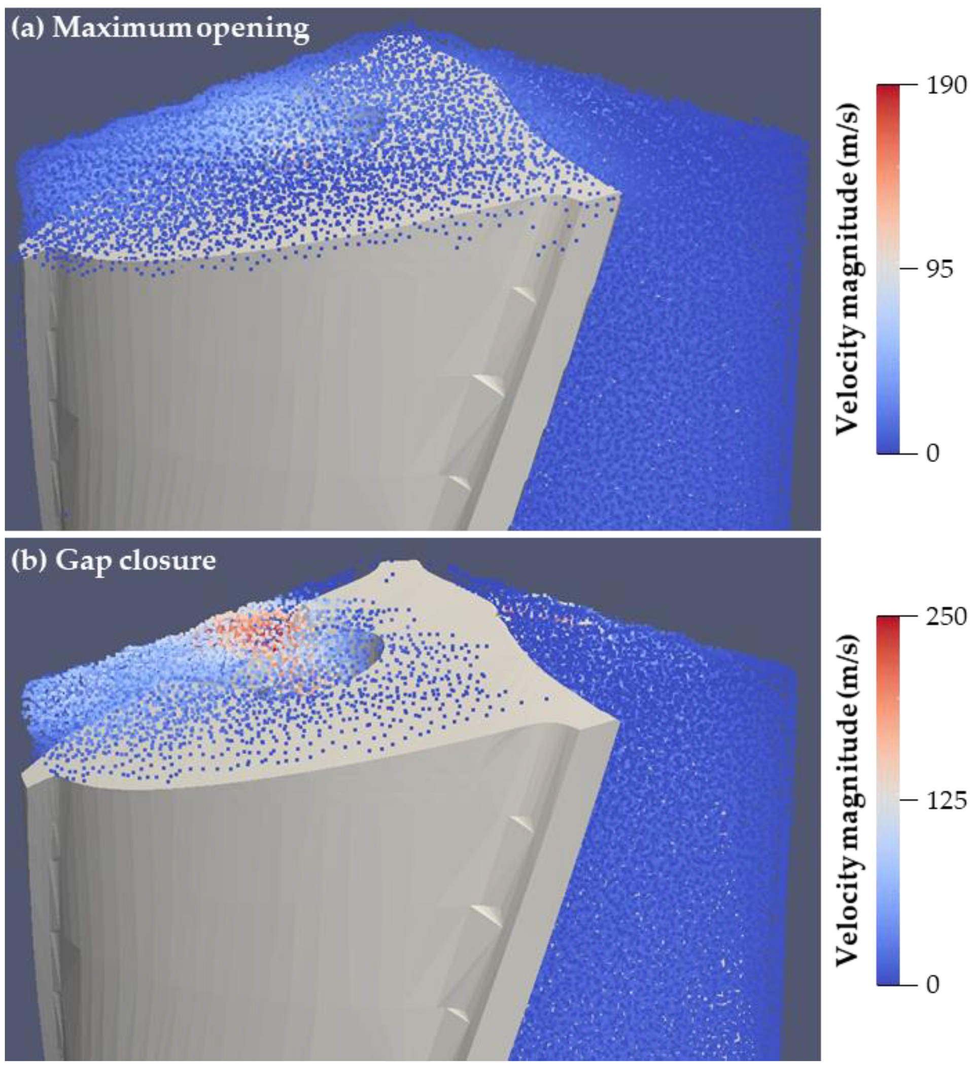
3.2. Single-Phase Flow in the Case of Vibrating Drill Bit

The second case is based on the drill bit geometry described in the previous section. Different from the previous case, the drill bit is now allowed to vibrate. The vibration frequency is 25 Hz, whereas the vibration amplitude is 120 μm. This amplitude is equal to the initial thickness of the gap between the drill bit and the borehole bottom. Therefore, it determines a complete closure of this gap during the vibration cycle (solid contact of the drill bit tip and the bore ground). Boundary/initial conditions and geometry have been taken equal to the previous case. An SPH simulation has been performed in order to assess the suitability of this mesh-less method to deal with a vibrating drill bit, as it occurs in vibration-assisted drilling processes.
Different from the SPH simulation with static boundaries, a lower particle resolution equal to 60 μm has been adopted. The decrease in resolution has been necessary due to the higher artificial speed of sound required to obtain a stable simulation for the present case. The speed of sound has been set approximately 30 times larger than the maximum fluid velocity in the domain (previously, it was only 10 times larger), yielding a value of about 6000. Under these conditions, a simulation of three vibration cycles, i.e., 0.12 s, takes about eight days of GPU computing. Adopting half of the resolution, i.e., 30 μm, as performed in the previous section, would have resulted in a prohibitive computational cost due to the severe time step restriction caused by the increased artificial speed of sound.
At the simulation startup, a distinct wall penetration of a few particles has been observed. As already pointed out in the previous section, the simulation startup can represent a critical moment due to the sudden acceleration of the fluid particles initialized to zero velocity. Additionally, the sudden onset of the drill bit vibration can act as an additional source of instability for the simulation. However, after this initial transient, the computation has run steadily until the final simulated physical time without showing this problem anymore.
Figure 4 shows the SPH particles colored by their velocity magnitude at two different time instants. The first time instant shown in Figure 4a corresponds to the moment of maximum opening of the gap between the drill bit and the borehole bottom.
On the contrary, a complete closure of this gap occurs at the second time instant shown in Figure 4b. The main point resulting from this figure is the correct reproduction of the flow dynamics during the vibration cycle. When the gap is open to the maximum possible extent, the air flow rate across the cutting edges reaches its highest value. However, when the gap closes completely, it can be observed that flow stops across the contact regions between the drill bit and the borehole bottom, as no SPH particles along the cutting edges are visible.

4. Conclusions and Outlook

In the present study, the possibility of employing an open-source SPH method to simulate the coolant/lubricant flow in vibration-assisted drilling processes working under MQL conditions was investigated. Despite the advantages over standard mesh-based methods of being free from complex, computationally very expensive and, sometimes, not viable dynamic meshing and/or re-meshing procedures to deal with moving boundaries in complex geometries, the simulation cases performed in this work have highlighted two main drawbacks of the SPH method:
(i)
The first problem relates to the solution accuracy. The comparison with the Finite-Volume-based code Ansys Fluent has shown an unsatisfactory matching of the results. This is mainly due to two reasons:
  • lack of variable particle resolution to capture large solution gradients (because increasing the resolution uniformly would lead to an intractable number of particles) and
  • poorly developed treatment of the turbulence.
(ii)
The second problem of SPH is about the computational cost. Although SPH is not subject to a relevant computational overhead to address the case of moving boundaries, a severe limitation on the time step to preserve the numerical stability has emerged from the second simulation case presented in the current study.
From the analysis shown, it emerges that SPH methods so far are not mature enough to address the problem of the two-phase flow of coolant/lubricant in vibration-assisted drilling processes in all its specific features. Further development work is necessary to overcome the weak points of the method. However, SPH has been attracting many researchers in the last decades, and many groups are currently working on its various deficiencies, e.g., variable particle resolution, turbulence modelling, computational cost. Thus, the present conclusion of this study might be revised, even in the near future, if these developments can be achieved, making it possible to exploit the very powerful features of the SPH method.
A single-phase flow has been considered in the present work. However, the coolant/lubricant in MQL consists of a mixture of air and oil. Therefore, a two-phase flow solver is needed to investigate numerically the MQL in drilling processes. At the current stage, DualSPHysics does not support a two-phase simulation with inlets/outlets, as required by the problem. To the authors’ knowledge, other SPH software packages, which allow two-phase SPH simulations with inlets/outlets, e.g., Pasimodo [35], are, however, limited to low density/viscosity ratios of the two phases and, thus, are not suitable for air/oil mixtures with physical properties that differ by several orders of magnitude.
Another way to tackle the description of the complex two-phase MQL flow in vibration-assisted drilling is to consider only the oil flow while neglecting the air flow. This simplification of the process may contribute at least to clarify the role of the oil phase in the wetting process and lubrication of the cutting zone, specifically in the vibrating case where frequently a surface is to be covered by the lubrication flow mainly coming from the oil. This configuration may be worth studying in future analysis.

Author Contributions

Conceptualization, L.B., M.F. and U.F.; methodology, M.F.; validation, L.B. and M.F.; formal analysis, M.F.; investigation, M.F.; resources, U.F.; data curation, L.B. and M.F.; writing—original draft preparation, L.B., M.F. and U.F.; writing—review and editing, L.B., M.F. and U.F.; visualization, L.B. and M.F.; supervision, U.F.; project administration, U.F.; funding acquisition, U.F. All authors have read and agreed to the published version of the manuscript.

Funding

This research was funded by the Deutsche Forschungsgemeinschaft—DFG, grant number FR 912/46-1, and is part of the project “Fully coupled simulation of the fluid dynamics of the coolant/lubricant flow and the cutting process in vibration-assisted drilling—ViBohr” within the SPP 2231 FluSimPro.

Conflicts of Interest

The authors declare no conflict of interest. The funders had no role in the design of the study; in the collection, analyses, or interpretation of data; in the writing of the manuscript, or in the decision to publish the results.

Nomenclature

FVMFinite-Volume method
GPUGraphics processing unit
MQLMinimum Quantity Lubrication
MWFMetalworking fluid
SPHSmoothed Particle Hydrodynamics
WCSPHWeakly Compressible Smoothed Particle Hydrodynamics
c0Speed of sound at the reference density (m s−1)
fGeneric quantity
gGravity vector (m s−2)
mMass of an SPH particle within the kernel radius (kg)
pPressure (Pa)
tTime (s)
VVelocity vector (m s−1)
WSmoothing kernel function
xSPH particle position (m)
Gradient operator
γSpecific heat ratio
ρDensity of an SPH particle within the kernel radius (kg m−3)
ρ0Reference density (kg m−3)
ΠabArtificial viscosity stabilization term
Subscripts a and b stand for different SPH particles

References

  1. Guba, N.; Schumski, L.; Paulsen, T.; Karpuschewski, B. Vibration-assisted deep hole drilling of the aluminum material AlMgSi0.5. CIRP J. Manuf. Sci. Technol. 2022, 36, 57–66. [Google Scholar] [CrossRef]
  2. Stephenson, D.A.; Agapiou, J.S. Metal Cutting Theory and Practice; CRC Press: Boca Raton, FL, USA, 2016. [Google Scholar]
  3. Kao, Y.-T.; Takabi, B.; Hu, M.; Tai, B.L. Coolant Channel and Flow Characteristics of MQL Drill Bits: Experimental and Numerical Analyses. In Proceedings of the 12th International Manufacturing Science and Engineering Conference, Los Angeles, CA, USA, 4–8 June 2017. [Google Scholar]
  4. Falcone, M.; Buss, L.; Fritsching, U. Eulerian–Lagrangian–Eulerian Simulations of Two-Phase Minimum Quantity Lubrication Flow in Internal Drill Bit Channels. Processes 2022, 10, 600. [Google Scholar] [CrossRef]
  5. Dasch, J.M.; Kurgin, S.K. A characterisation of mist generated from minimum quantity lubrication (MQL) compared to wet machining. Int. J. Mach. Mach. Mater. 2010, 7, 82–95. [Google Scholar] [CrossRef]
  6. Stephenson, D.A.; Hughey, E.; Hasham, A.A. Air flow and chip removal in minimum quantity lubrication drilling. Procedia Manuf. 2019, 34, 335–342. [Google Scholar] [CrossRef]
  7. Raval, J.K.; Hung, W.N.P.; Tai, B.L. Multiphase Flow Distribution in MQL Drilling Using Optical Intensity Distribution Based Approach. In Proceedings of the 14th International Manufacturing Science and Engineering Conference, Erie, PA, USA, 10–14 June 2019. [Google Scholar]
  8. Patil, A.; Raval, J.; Bangma, T.; Edinbarough, I.; Tai, B.; Stephenson, D.; Suleiman, O.; Hung, W.N. Characterization and Performance of Minimum Quantity Lubricants in Through-Tool Drilling. Int. J. Eng. Mater. Manuf. 2020, 5, 98–115. [Google Scholar] [CrossRef]
  9. Raval, J.K.; Kao, Y.-T.; Tai, B.L. Characterizing Mist Distribution in Through-Tool Minimum Quantity Lubrication Drills. J. Manuf. Sci. Eng. 2020, 142, 1–16. [Google Scholar] [CrossRef]
  10. Gingold, R.A.; Monaghan, J.J. Smoothed particle hydrodynamics: Theory and application to non-spherical stars. Mon. Not. R. Astron. Soc. 1977, 181, 375–389. [Google Scholar] [CrossRef]
  11. Lucy, L.B. A numerical approach to the testing of the fission hypothesis. Astron. J. 1977, 82, 1013–1024. [Google Scholar] [CrossRef]
  12. Monaghan, J.J. Smoothed Particle Hydrodynamics. Annu. Rev. Astron. Astrophys. 1992, 30, 543–574. [Google Scholar] [CrossRef]
  13. Fourtakas, G.; Rogers, B.D.; Laurence, D.R. Modelling sediment resuspension in industrial tanks using SPH. Houille Blanche 2013, 99, 39–45. [Google Scholar] [CrossRef]
  14. Fourtakas, G.; Rogers, B.D. Modelling multi-phase liquid-sediment scour and resuspension induced by rapid flows using Smoothed Particle Hydrodynamics (SPH) accelerated with a Graphics Processing Unit (GPU). Adv. Water Resour. 2016, 92, 186–199. [Google Scholar] [CrossRef]
  15. Aureli, F.; Dazzi, S.; Maranzoni, A.; Mignosa, P.; Vacondio, R. Experimental and numerical evaluation of the force due to the impact of a dam-break wave on a structure. Adv. Water Resour. 2015, 76, 29–42. [Google Scholar] [CrossRef]
  16. Hosain, M.L.; Domínguez, J.M.; Bel Fdhila, R.; Kyprianidis, K. Smoothed particle hydrodynamics modeling of industrial processes involving heat transfer. Appl. Energy 2019, 252, 113441. [Google Scholar] [CrossRef]
  17. Raizah, Z.; El-Sapa, S.; Aly, A.M. ISPH simulations of thermosolutal convection in an annulus amongst an inner prismatic shape and outer cavity including three circular cylinders. Case Stud. Therm. Eng. 2022, 30, 101736. [Google Scholar] [CrossRef]
  18. Altomare, C.; Crespo, A.J.C.; Domínguez, J.M.; Gómez-Gesteira, M.; Suzuki, T.; Verwaest, T. Applicability of Smoothed Particle Hydrodynamics for estimation of sea wave impact on coastal structures. Coast. Eng. 2015, 96, 1–12. [Google Scholar] [CrossRef]
  19. Altomare, C.; Domínguez, J.M.; Crespo, A.J.C.; Suzuki, T.; Caceres, I.; Gómez-Gesteira, M. Hybridization of the Wave Propagation Model SWASH and the Meshfree Particle Method SPH for Real Coastal Applications. Coast. Eng. J. 2015, 57, 1–34. [Google Scholar] [CrossRef]
  20. Pringgana, G.; Cunningham, L.S.; Rogers, B.D. Modelling of tsunami-induced bore and structure interaction. Proc. Inst. Civ. Eng. Eng. Comput. Mech. 2016, 169, 109–125. [Google Scholar] [CrossRef] [Green Version]
  21. Heller, V.; Bruggemann, M.; Spinneken, J.; Rogers, B.D. Composite modelling of subaerial landslide–tsunamis in different water body geometries and novel insight into slide and wave kinematics. Coast. Eng. 2016, 109, 20–41. [Google Scholar] [CrossRef]
  22. Crespo, A.J.C.; Altomare, C.; Domínguez, J.M.; González-Cao, J.; Gómez-Gesteira, M. Towards simulating floating offshore oscillating water column converters with Smoothed Particle Hydrodynamics. Coast. Eng. 2017, 126, 11–26. [Google Scholar] [CrossRef]
  23. Altomare, C.; Tagliafierro, B.; Dominguez, J.M.; Suzuki, T.; Viccione, G. Improved relaxation zone method in SPH-based model for coastal engineering applications. Appl. Ocean Res. 2018, 81, 15–33. [Google Scholar] [CrossRef]
  24. Domínguez, J.M.; Altomare, C.; Gonzalez-Cao, J.; Lomonaco, P. Towards a more complete tool for coastal engineering: Solitary wave generation, propagation and breaking in an SPH-based model. Coast. Eng. J. 2019, 61, 15–40. [Google Scholar] [CrossRef]
  25. González-Cao, J.; Altomare, C.; Crespo, A.J.C.; Domínguez, J.M.; Gómez-Gesteira, M.; Kisacik, D. On the accuracy of DualSPHysics to assess violent collisions with coastal structures. Comput. Fluids 2019, 179, 604–612. [Google Scholar] [CrossRef]
  26. Lowe, R.J.; Buckley, M.L.; Altomare, C.; Rijnsdorp, D.P.; Yao, Y.; Suzuki, T.; Bricker, J.D. Numerical simulations of surf zone wave dynamics using Smoothed Particle Hydrodynamics. Ocean Model. 2019, 144, 101481. [Google Scholar] [CrossRef] [Green Version]
  27. Verbrugghe, T.; Stratigaki, V.; Altomare, C.; Domínguez, J.M.; Troch, P.; Kortenhaus, A. Implementation of Open Boundaries within a Two-Way Coupled SPH Model to Simulate Nonlinear Wave–Structure Interactions. Energies 2019, 12, 697. [Google Scholar] [CrossRef] [Green Version]
  28. Altomare, C.; Tafuni, A.; Domínguez, J.M.; Crespo, A.J.C.; Gironella, X.; Sospedra, J. SPH Simulations of Real Sea Waves Impacting a Large-Scale Structure. J. Mar. Sci. Eng. 2020, 8, 826. [Google Scholar] [CrossRef]
  29. Pringgana, G.; Cunningham, L.S.; Rogers, B.D. Influence of Orientation and Arrangement of Structures on Tsunami Impact Forces: Numerical Investigation with Smoothed Particle Hydrodynamics. J. Waterw. Port Coast. Ocean Eng. 2021, 147, 04021006. [Google Scholar] [CrossRef]
  30. O’Connor, J.; Rogers, B.D. A fluid–structure interaction model for free-surface flows and flexible structures using smoothed particle hydrodynamics on a GPU. J. Fluids Struct. 2021, 104, 103312. [Google Scholar] [CrossRef]
  31. Lowe, R.J.; Altomare, C.; Buckley, M.L.; da Silva, R.F.; Hansen, J.E.; Rijnsdorp, D.P.; Domínguez, J.M.; Crespo, A.J.C. Smoothed Particle Hydrodynamics simulations of reef surf zone processes driven by plunging irregular waves. Ocean Model. 2022, 171, 101945. [Google Scholar] [CrossRef]
  32. English, A.; Domínguez, J.M.; Vacondio, R.; Crespo, A.J.C.; Stansby, P.K.; Lind, S.J.; Chiapponi, L.; Gómez-Gesteira, M. Modified dynamic boundary conditions (mDBC) for general-purpose smoothed particle hydrodynamics (SPH): Application to tank sloshing, dam break and fish pass problems. Comput. Part. Mech. 2021, 1–15. [Google Scholar] [CrossRef]
  33. Green, M.D.; Zhou, Y.; Dominguez, J.M.; Gesteira, M.G.; Peiró, J. Smooth particle hydrodynamics simulations of long-duration violent three-dimensional sloshing in tanks. Ocean Eng. 2021, 229, 108925. [Google Scholar] [CrossRef]
  34. Manenti, S.; Wang, D.; Domínguez, J.M.; Li, S.; Amicarelli, A.; Albano, R. SPH Modeling of Water-Related Natural Hazards. Water 2019, 11, 1875. [Google Scholar] [CrossRef] [Green Version]
  35. Schnabel, D.; Özkaya, E.; Biermann, D.; Eberhard, P. Modeling the motion of the cooling lubricant in drilling processes using the finite volume and the smoothed particle hydrodynamics methods. Comput. Methods Appl. Mech. Eng. 2018, 329, 369–395. [Google Scholar] [CrossRef]
  36. Schnabel, D.; Özkaya, E.; Biermann, D.; Eberhard, P. Transient Simulation of Cooling-Lubricant Flow for Deep-Hole Drilling-Processes. Procedia CIRP 2018, 77, 78–81. [Google Scholar] [CrossRef]
  37. Baumann, A.; Oezkaya, E.; Schnabel, D.; Biermann, D.; Eberhard, P. Cutting-fluid flow with chip evacuation during deep-hole drilling with twist drills. Eur. J. Mech. B Fluids 2021, 89, 473–484. [Google Scholar] [CrossRef]
  38. Crespo, A.J.C.; Domínguez, J.M.; Rogers, B.D.; Gómez-Gesteira, M.; Longshaw, S.; Canelas, R.; Vacondio, R.; Barreiro, A.; García-Feal, O. DualSPHysics: Open-source parallel CFD solver based on Smoothed Particle Hydrodynamics (SPH). Comput. Phys. Commun. 2015, 187, 204–216. [Google Scholar] [CrossRef]
  39. Wendland, H. Piecewise polynomial, positive definite and compactly supported radial functions of minimal degree. Adv. Comput. Math. 1995, 4, 389–396. [Google Scholar] [CrossRef]
  40. Domínguez, J.M.; Fourtakas, G.; Altomare, C.; Canelas, R.B.; Tafuni, A.; García-Feal, O.; Martínez-Estévez, I.; Mokos, A.; Vacondio, R.; Crespo, A.J.C.; et al. DualSPHysics: From fluid dynamics to multiphysics problems. Comput. Part. Mech. 2021, 1–29. [Google Scholar] [CrossRef]
  41. Monaghan, J.J.; Kos, A. Solitary Waves on a Cretan Beach. J. Waterw. Port Coast. Ocean Eng. 1999, 125, 145–155. [Google Scholar] [CrossRef]
  42. Crespo, A.J.C.; Gómez-Gesteira, M.; Dalrymple, R.A. Boundary Conditions Generated by Dynamic Particles in SPH Methods. Comput. Mater. Contin. 2007, 5, 173–184. [Google Scholar] [CrossRef]
Figure 1. Sketch of the drill bit: (a) side-view; the internal helical channel is highlighted; the MWF is transported through the internal channel to the cutting zone (b) details of the drill bit tip and flow direction (blue and green arrows) and vibration of the drill bit (red left-right arrow). Dimensions of the numerical domain are presented in Table 1.
Fluids 07 00189 g001
Figure 2. Geometry of benchmark case for comparison between open-source SPH code DualSPHysics and commercial code Ansys Fluent. (a) full geometry and (b) longitudinal section.
Fluids 07 00189 g002
Figure 3. Color plots of axial velocity on a longitudinal section of the fluid domain: comparison of results obtained with (a) open-source DualSPHysics code and (b) commercial code Ansys Fluent.
Fluids 07 00189 g003
Figure 4. SPH particles colored by velocity magnitude at two different time instants of the simulation: (a) maximum opening of the gap between the drill bit and hole bottom and (b) complete closure of the gap, including the drill bit vibration.
Fluids 07 00189 g004
Table 1. Geometric dimensions of the numerical domain and operating conditions.
ParameterValue
Domain length (tip of the drill bit)8.0 mm
Drill bit diameter5.0 mm
Internal channel diameter0.7 mm
Vibration amplitude120 µm
Vibration frequency25 Hz
Publisher’s Note: MDPI stays neutral with regard to jurisdictional claims in published maps and institutional affiliations.

