Article

Effect of Nozzle Port Shape of Fuel Injector of Micro Gas Turbine Engine Combustor on Mixture Gas Formation for Combustion

1
Department of Automotive Engineering, Graduate School, Seoul National University of Science & Technology, Seoul 01811, Korea
2
Department of Mechanical & Automotive Engineering, Seoul National University of Science & Technology, Seoul 01811, Korea
*
Author to whom correspondence should be addressed.
Fluids 2022, 7(6), 184; https://doi.org/10.3390/fluids7060184
Submission received: 28 April 2022 / Revised: 23 May 2022 / Accepted: 24 May 2022 / Published: 26 May 2022

Abstract

:
The objective of this study was to optimize the design of the injection nozzle hole of the fuel injector of a model MGT engine. To achieve a higher combustion efficiency of the mixed gas in the combustion chamber, first, well-mixed homogeneous gas should be formed to accelerate the flame propagation in the chamber to reach a higher combustion temperature and pressure. In this study, four different shapes of the nozzle hole of the fuel injector were designed, and the mixed gas formation characteristics in the chamber were numerically analyzed. Three parameters—the penetration, diffusivity, and amount of fuel injected—were analyzed and compared to find the optimum shape of the nozzle hole with the highest combustion efficiency in the chamber. CFD analysis was conducted using a general-purpose CFD (Computational Fluid Dynamics) code-named PHOENICS (ver. 2020). Based on the analysis results, it was found that the penetration length ( l p ), diffusion angle (θ), and volume flow rate ( Q ˙ f ) of the injected fuel of Model 3 had the best injection characteristics for the well-mixed gas formation condition in the combustion chamber. Especially, the volume flow rate of the injected fuel of Model 3, which directly affects the output power of the engine, increased by more than 5%. This result is useful and informative for making a sample combustor for a combustion performance test of the model gas turbine engine.

1. Introduction

Global warming and the energy shortage problem have become essential issues that mankind must solve in the 21st century. In the past few years, the electric power industry has been rapidly shifting from pyroelectric power generation to power generation using renewable energy, such as solar power, wind power, and hydropower. At the same time, global electricity demand is steadily increasing. As the trend of electrification in various fields, starting with electric vehicles, is becoming stronger, it is important worldwide to develop a sustainable solution to the increasing demand for electricity. In Asia, coal-fired power plants are being replaced by gas turbines running on natural gas that emit 60% less carbon than coal-fired power plants [1,2]. However, due to the high entry barriers for gas-turbine-related technologies and the avoidance of technology transfer by advanced overseas companies, foreign institutions have monopolized the market leadership [3,4], resulting in huge import costs. In particular, medium and large gas turbines must be imported at high prices, including complex structures, huge volumes, and specialized cooling towers. As a result, interest in distributed generation systems using micro gas turbines has increased. Compared with gas turbines used in medium and large gas turbines, micro gas turbines of smaller size and with excellent operating performance are more likely to attract attention [5,6].
A micro gas turbine (MGT) is an energy generator with a capacity range of 15 to 300 kW. NASA classifies gas turbine classes according to maximum thrust, as shown in Table 1 [7]. It offers several common features, such as variable speed, high-speed operation, small size, simple operability, easy installation, low maintenance, air bearing, low NOx emissions, and generally serves as a recuperator. Most of the design characteristics of general gas turbines are reflected, and operational reliability and maintainability are good, so it is widely used in distributed generation systems [8]. Typical MGTs have a pressure ratio of 3 to 5 and an efficiency of 25 to 30%. In the case of the United States, research was conducted to develop an MGT system with an efficiency of 40% led by the DOE (Department of Energy) [9]. In Korea, the development of tens to hundreds of kW class micro gas turbines is also planned [10]. A suitability analysis for commercial micro gas turbines was also performed [11,12,13]. Methods to improve performance are also being studied [14,15]. In this study, development is underway intending to commercialize a 300 kW micro gas turbine engine.
In particular, the design of a low-NOx combustor has become a very important research subject [16,17]. As the main cause of NOx generation is the high combustion temperature due to the rich mixture formed in the combustion chamber, the solution is the optimum design of the first to third compressed air supply zones configured in the inner combustor liner [18,19]. In particular, the combustion temperature in the first combustion zone is affected by the generation characteristics of the mixed gas [20,21].
This study aims to develop an optimal fuel injector for the combustion chamber of a 300 kW class MGT engine under development. The shape of the nozzle hole formed on the surface of the fuel injector is the critical parameter of the fuel injector design for the formation of the well-mixed homogeneous gas charged in the combustion chamber.
In here, four different model injectors were designed with different nozzle hole shapes on the wall of the injector. For the analysis of the pre-mixed and diffusion characteristics of the mixed gas in the primary combustion zone of each model injector, penetration length ( l P ), diffusion angle (θ), and volume flow rate ( Q ˙ f ) of the injected fuel were analyzed and quantitatively compared to each other to find the optimized model.
For this numerical study, a general-purpose commercial CFD code, PHOENICS (ver. 2020) from CHAM, which applies the FVM (finite volume method), was used for the numerical calculation of the turbulent incompressible flow field [22].

2. Specification of the Model Combustor with the Fuel Injector

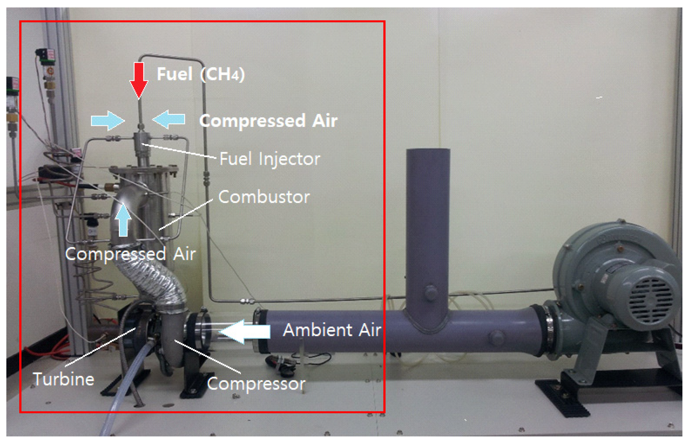
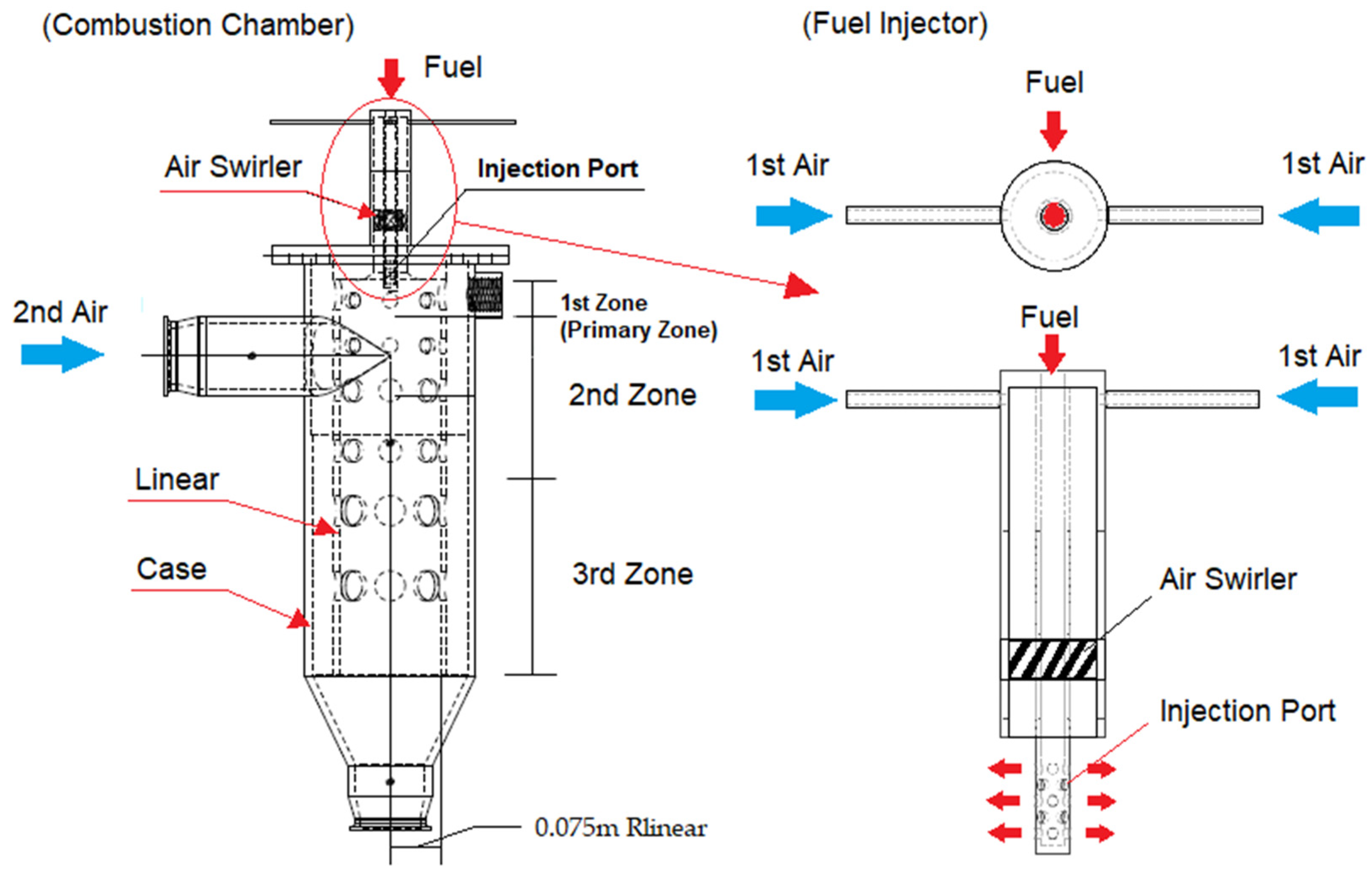
2.1. Structure of the Combustion Chamber of the Model MGT Engine

Figure 1 is a prototype model for testing the designed MGT engine combustion chamber. Compressed air is supplied by a blower to generate mixed gas in the combustion chamber. Combustion of the mixed gas starts through the ignition device. After combustion, the energy of the exhaust gas rotates the turbine wheel, and the air sucked in by the compressor is compressed and sent to the combustion chamber.
Figure 2 shows a schematic of the combustion chamber applied to the model MGT engine. It uses gaseous methane (CH4) as the fuel, which is injected into the combustion chamber at a pressure of 6~9 bar through the injection port of the fuel injector. Compressed air is supplied into the combustion chamber in two ways, in this case through the first and second airlines. The first compressed airline is for mixed gas formation to start combustion, and the second airline supplies air through the side duct of the combustion chamber for the main combustion and cooling of the combusted gas before the compressor turbine [21,23]. The compressed air through the first line passes through a swirler and mixes with the fuel at the exit of the injection ports to generate the mixture for combustion.

2.2. Geometry of the Model Fuel Injector

Figure 3 shows the configuration of the model fuel injector applied to the model MGT engine. It has five rows of injection ports, and each row has four ports with the same diameter (5.35 mm). As fuel goes through the port, the fuel particles encounter the swirled air particles at the port’s exit to form the mixed gas. To ensure a well-mixed gas for higher combustion efficiency in the combustion chamber, three factors should be noted: penetration, diffusivity, and the fuel flow rate at the given injection condition.

3. Governing Equation and Analysis Conditions

3.1. Governing Equation

Three-dimensional Navier–Stokes equations were solved with the KECHEN turbulent model (Chen-Kim κ-ε model) [22], which is a modified standard κ-ε turbulent model. The turbulent no-slip condition near the solid surface was modeled by the log law.
The Chen-Kim κ-ε model is believed to improve the dynamic response of an epsilon equation by introducing an additional time scale and source term. In addition, several of the standard-model coefficients are adjusted so that the model maintains a good agreement with the experimental data on classical turbulent shear layers [22,24].
The injection pressure of the model injector was set to 100 kPa, and the fuel injection speed at the nozzle exit was less than 30 m/s due to the flow resistance in the flow channel of the injector; thus, the flow in the control volume was assumed to be an incompressible flow.
For simplification of the boundary conditions for the analysis, the airflow field was defined as follows.
  • Three-dimensional steady flow.
  • Incompressible and turbulent flow.
  • Isothermal flow.
To determine the convergence of the calculation result, calculations were repeatedly performed until the residual fraction of each variable fell to 10−4% or less. The governing equations for the simulation of the turbulent flow field are as follows [25].
(1)
Continuity equation:
U i x i = 0
(2)
Momentum equation:
x j ( U i U j ) = 1 ρ P x i + x j [ v ( U i x j + U j x i ) u i u j ¯ ] g i
where u i u j ¯ = v t ( U i x j + U j x i ) 2 3 k δ i j , δ i j = 1   if   i = j   and   δ i j = 0   if   i j
where u is the particle velocity vector and g is the gravity vector.
(3)
Extended k-ε closure turbulent model (KECHEN) equation.
x i ( U j k ) = x i [ ( v + v t σ k ) k x j ] + G ε
where G = u i u j ¯ U i x j ,   v t = C μ k 2 ε , C μ = 0.09
where k is the turbulent kinetic energy and ε is the energy dissipation rate.
(4)
Energy dissipation equation:
x i ( U j ε ) = x i [ ( v + v t σ ε ) ε x j ] + ε k ( C ε 1 G ) C ε 2 ε 2 k ) + C ε 3 f 1 P k 2 K
where ( C μ = 0.09 ,   C δ 1 = 1.15 , C δ 2 = 1.9 ,   C δ 3 = 0.25 , σ κ = 0.75 ,   σ δ = 1.15 )

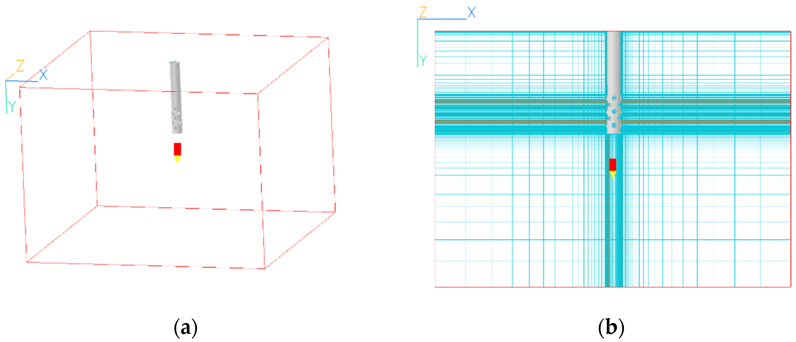
3.2. Numerical Domain and the Optimized Grid

A solid model of the fuel injector was created using ProEngineer (Ver. 5.0), a general-purpose 3D CAD program, and the solid model was imported into the numerical domain to create a hexagonal grid in the Cartesian coordinate system [26,27].
Figure 4a shows the computational domain size for the numerical analysis. To increase the reliability of the simulation result, a sufficient domain size was utilized for the region around the model fuel injector so that the flow field would sufficiently develop within the test volume.
Figure 4b shows a typical numerical grid used to analyze the generation character-istics of mixed gas in the combustion chamber. The optimum grid size in the control volume was determined to be (84 × 145 × 84) which showed y+ = 1 of the first grid element in the near-wall layer through a grid test [28].

3.3. Boundary and Initial Condition

Methane in a gas phase is injected into the airfield in the combustion chamber; thus, this is a single-phase flow problem. When fuel is completely burned, the air–fuel ratio is calculated as 17.2:1, and the injection speed is defined as 300 m/s as shown in Table 2. All of the domain surfaces were defined as an ambient pressure condition.

3.4. Configuration of the Model’s Nozzle Port

In this study, the shape of the nozzle port is the prime variable with which to analyze the characteristics of the mixture gas formation for higher combustion efficiency in the model MGT engine [29,30].
Table 3 shows the four different shapes of the nozzle port. Model 1 is a base model in which the injection nozzle hole is drilled in the vertical direction toward the injector surface, and the port has a sharp right-angle edge. In Model 2 to Model 4, the shape of the inlet and outlet of the port is rounded with a radius of curvature of 1 mm to obtain different characteristics of mixture formation in the combustion chamber.

4. Results and Discussion
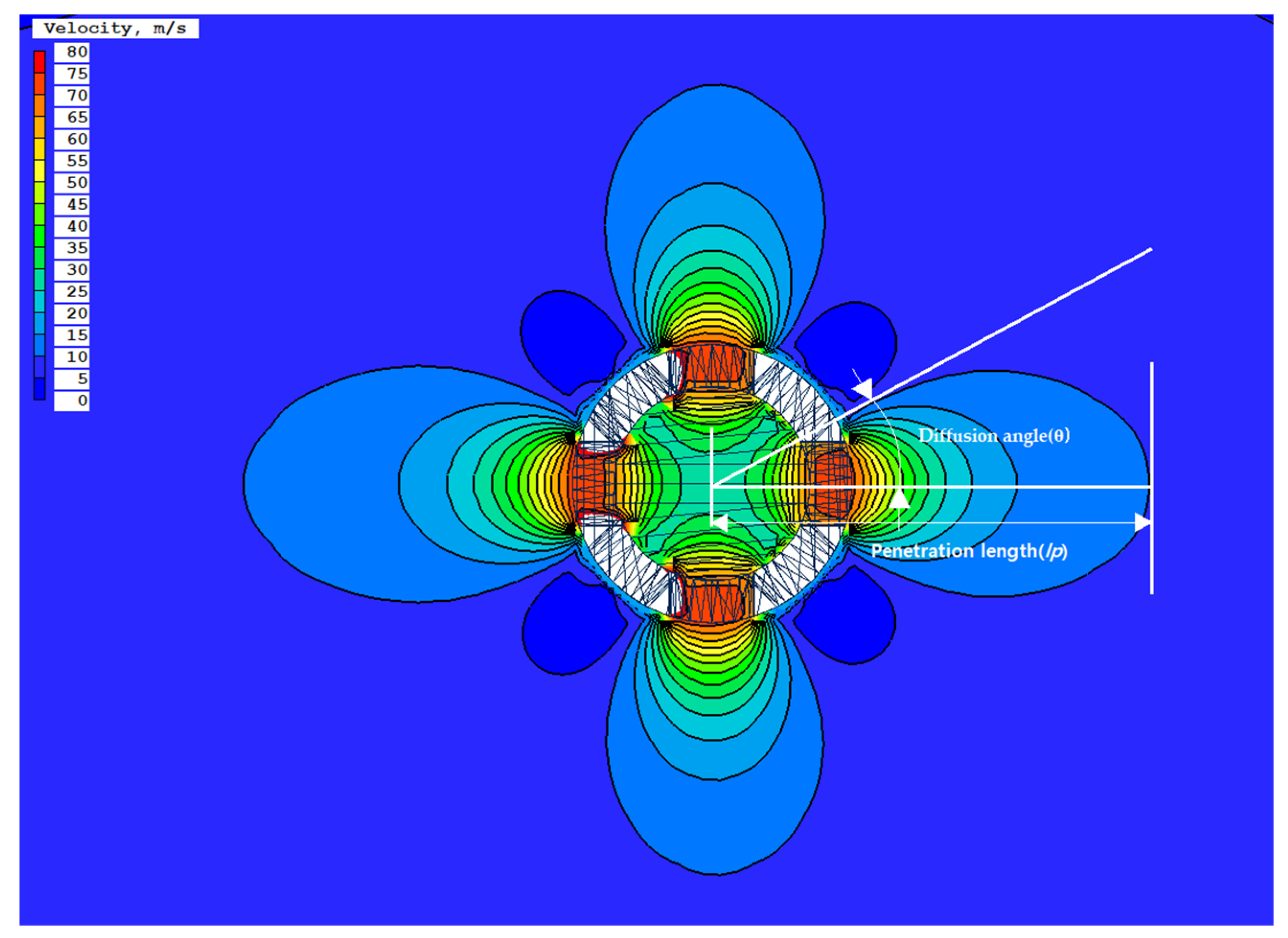
The effect of the port shape of the injection nozzle on the mixture gas generation in the model combustion chamber was analyzed. To analyze the formation characteristics of a homogeneous gas mixture, the following parameters of the injected fuel were analyzed in the mixing zone in the vicinity of the exit of the injection nozzle [31].
  • Penetration.
  • Diffusivity.
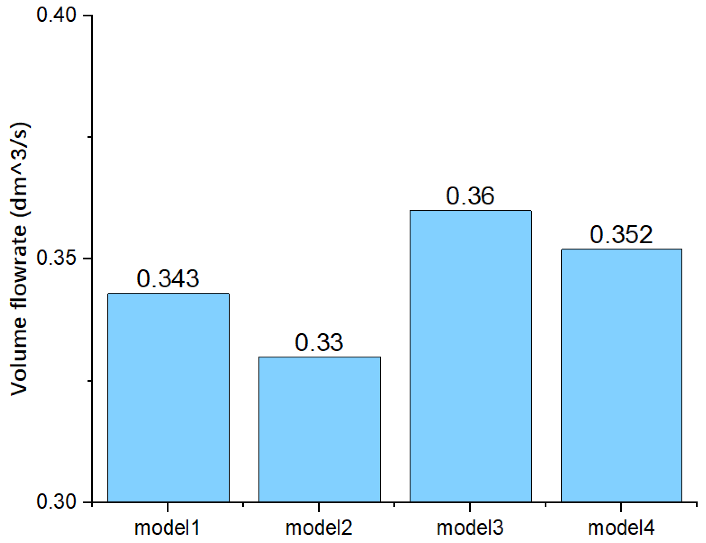
  • Volume flowrate of the injected fuel.

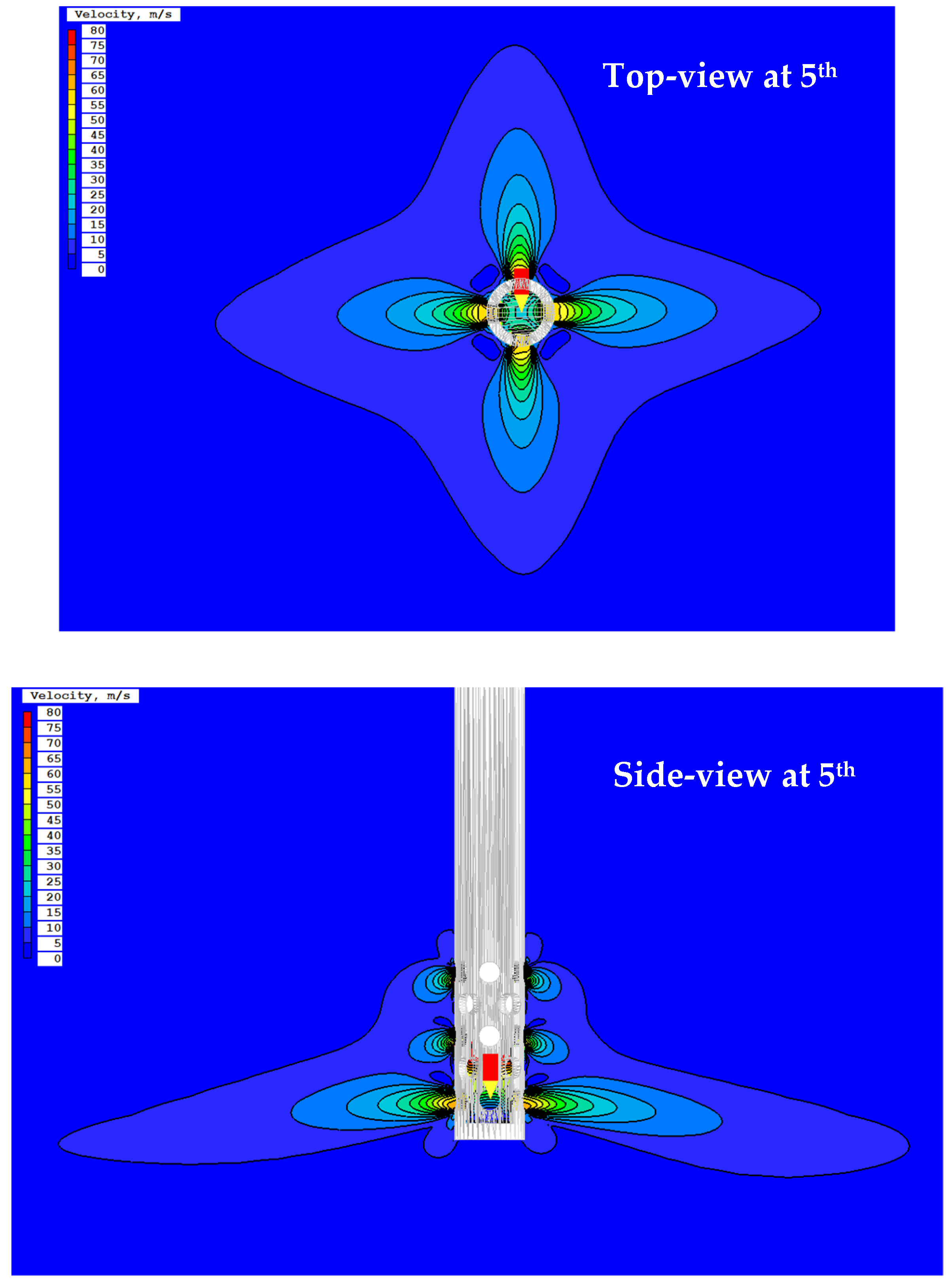
4.1. Flow Phenomena of the Mixed Gas at the Exit of the Injection Ports

Figure 5 shows the fuel injection phenomenon around the fuel injector (Model 1). The right picture shows the side view of the injection injector, and it found that the fuel injected into the air through the nozzle ports mixes with the surrounding air to create a mixed gas and diffuses into the combustion chamber. However, more fuel is injected at the fifth row of the ports due to the higher accumulated injection pressure at the lower part of the fuel injector, as in Figure 6. The penetration length and the divergent angle of the mixed gas seriously affect the higher combustion efficiency of the combustor.

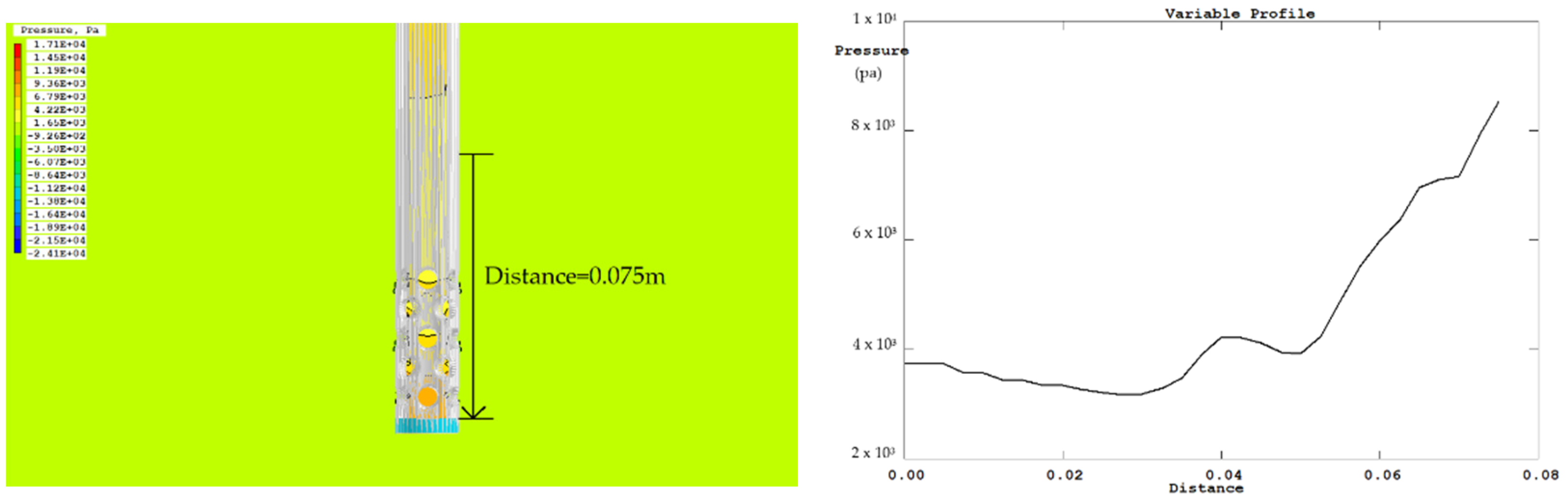
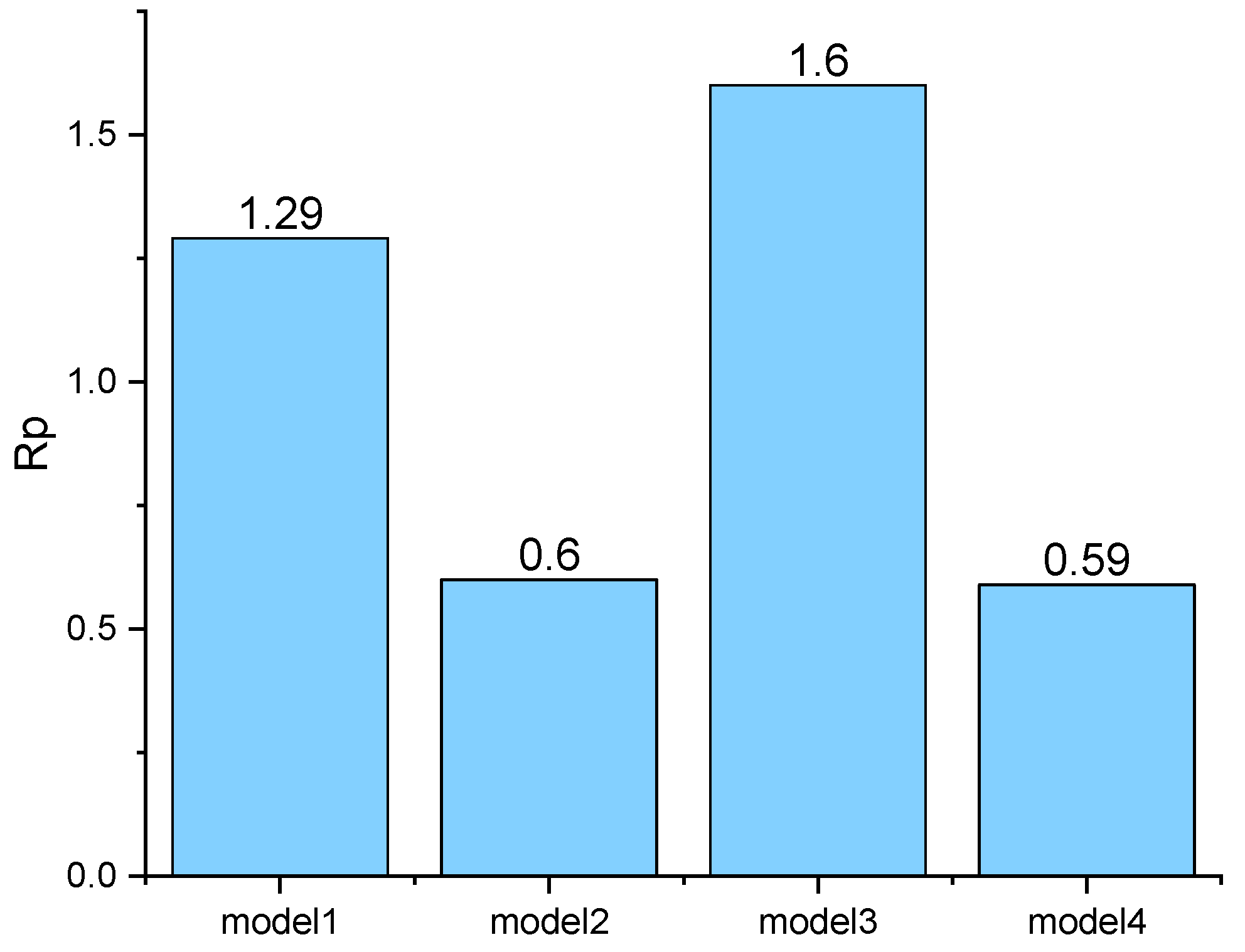
4.2. Analysis of Simulation Results

To evaluate the performance of the fuel injector of the model MGT engine, four parameters—the penetration, diffusivity, vaporization for mixing, and the volume flow rate of the injected gas fuel—are estimated. However, methane (CH4) in the gas phase is used as fuel. Thus, vaporization is not a considerable parameter in this study. The diffusion angle (θ) and the penetration length ( l p ) of the mixed gas in the combustion chamber are defined as shown in Figure 7.
The penetration, diffusivity, and the volumetric flow rate of the mixed gas in the flow domain were compared for the four different model injectors to compare the formation characteristics of the mixed gas.
Figure 7 shows the contour plot of the injection velocity around the nozzle holes in the fifth row. The length from the center of the nozzle to the endpoint of the fuel particles in the horizontal direction was defined as the penetration length ( l p ), and the maximum spreading angle through the nozzle hole was defined as the diffusion angle (θ). The penetrability, diffusivity, and volume flow rate of fuel injected from each model injector were analyzed and compared to evaluate the mixed gas formation characteristics in the chamber:
R p = l p R l i n e r
where R l i n e r is the radius of the liner, which is the inner cylinder in the combustion chamber.
Figure 8 shows the changes of the R p , which indicates the penetration rate of the mixed gas for each nozzle model. Model 3 showed the biggest R p . If the injection distance is greater, it is advantageous for the homogenization of the mixed gas inside the combustion chamber.
Figure 9 compares the diffusion angle (θ) of the injected fuel for each nozzle model. The Model 3 injector has the widest diffusion angle, and it is observed that this works favorably for a homogeneously mixed gas spread widely in the combustion region for a higher combustion speed in the combustion chamber.
Figure 10 compares the amount of fuel injected into the air for each nozzle model. The injected fuel flow rate of Model 3 is the highest among the model injectors. It has 5% more fuel injected into the domain than the base Model 1. Thus, it is assumed that the injection performance of Model 3 is advantageous for the generation of higher output power.

5. Conclusions

In this numerical study, the characteristics of mixed gas formation, which affects the combustion efficiency and out-power, were analyzed to obtain the optimum fuel injector design of a 300 kW class MGT engine under development.
For the analysis of the mixed gas formation characteristics of four different models of the injection port of the fuel injector developed in this research, three physical parameters—penetrability, diffusivity, and volume flow rate of injected fuel—were analyzed and compared. The results of the study are summarized below.
(1) Model 3, with a rounded inlet surface, injects the mixed gas farthest and widest in the combustion region among the models tested here at the given injection speed. It is expected that the flame propagates deeper and wider into the combustion chamber with a strong flame front, resulting in higher combustion efficiency in Model 3.
(2) The volume flow rate of the injected fuel affects the combustion temperature and pressure in the combustion chamber, and it is directly related to the output power of the power turbine of the model MGT engine. Here, it was found that Model 3 has the highest fuel mass flow rate injected into the combustion chamber among the model injectors tested, and it has 5% more fuel injected into the combustion chamber than the base Model 1.
Overall, the Model 3 injector, with its rounded inlet surface, was found to be the best fuel injector for the generation of a homogeneously mixed gas formation for higher combustion efficiency and a higher mass flow rate of fuel injected into the chamber for a higher output power of the model gas turbine engine tested in this study.

Author Contributions

The contributions of each author to this paper are as follows. Conceptualization, Y.H. and C.-H.K.; methodology, Y.H. and C.-H.K.; software, Y.H.; validation, Y.H.; formal analysis, Y.H. and C.-H.K.; investigation, Y.H.; resources, Y.H.; data curation, Y.H.; writing—original draft preparation, Y.H.; writing—review and editing, Y.H. and C.-H.K.; visualization, Y.H.; supervision, C.-H.K.; project administration, C.-H.K.; funding acquisition, C.-H.K. All authors have read and agreed to the published version of the manuscript.

Funding

This research received no external funding.

Institutional Review Board Statement

Not applicable.

Informed Consent Statement

Not applicable.

Data Availability Statement

Not applicable.

Acknowledgments

The authors thank to the Industry-University Cooperation Foundation and the Office of International Education of Seoul National University of Science and Technology for the support.

Conflicts of Interest

The authors declare no conflict of interest.

References

  1. Future of energy report. In Proceedings of the 26th UN Climate Change Conference of the Parties (COP26), Glasgow, UK, 31 October–13 November 2021.
  2. Jang, S.H. Gas Turbine Optimum Operation Support System for Power Generation. In Proceedings of the 2019 Asia Pacific Gas Conference, Bali, Indonesia, 29–31 October 2019. [Google Scholar]
  3. Basic Electricity Supply and Demand Plan 8th; Korea Ministry of Trade, Industry and Energy: Sejong City, Korea, 2017; p. 611.
  4. Jung, S.H.; Youn, S.J.; Noh, T.W.; Kang, S.Y.; Jung, M.H.; Woo, T.K. Repair Maintenance Technology for High Temperature Components in Gas Turbine. J. Korean Soc. Comput. Fluids Eng. 2021, 12, 58–61. [Google Scholar]
  5. Shin, H.D.; Kang, D.W.; Kim, T.S.; Choi, M.K.; Park, P.J. Design Parameter Sensitivity Analysis of a 200 Kw Class Micro Gas Turbine System. J. Fluid Mach. 2012, 15, 39–45. [Google Scholar] [CrossRef]
  6. Hamilton, S.L. Microturbines Distributed Generation: A Nontechnical Guide; Chambers, A., Ed.; PennWell Corporation: Nashville, TN, USA, 2001; pp. 33–72. [Google Scholar]
  7. Sehra, A.K.; Shin, J. Revolutionary Propulsion Systems for 21st Century Aviation; NASA: Washington, DC, USA, 2003; p. TM-2003-212615.
  8. Rodgers, C.; Watts, I.; Nichols, K.; Brent, R. Microturbines. In Distributed Generation; Borbely, A.M., Kreider, J., Eds.; CRC Press: Boca Raton, FL, USA, 2001; pp. 119–150. [Google Scholar]
  9. Capstone Turbine Corporation. Advanced Micro Turbine System (AMTS) Final Technical Report; U.S Department of Energy, DOE Project: Washington, DC, USA, 2008; p. 155.
  10. Oh, J.S.; Lee, H.S. Prototype Development of A 75 Kw Class Micro Turbine Design/Manufacture and Self-Sustaining Test. J. Fluid Mach. 2002, 12, 307–313. [Google Scholar]
  11. Lee, J.J.; Kim, T.S. Analysis of Operation Performance of a Micro Gas Turbine Generator System. J. Fluid Mach. 2004, 8, 13–21. [Google Scholar]
  12. Lee, J.J.; Yoon, J.E.; Kim, T.S. Operation Simulation of a Microturbine Based on Test Data. J. Fluid Mach. 2006, 9, 22–28. [Google Scholar]
  13. Lee, J.J.; Yoon, J.E.; Kim, T.S.; Sohn, I.L. Performance Test and Component Characteristics Evaluation of a Micro Gas Turbine. J. Mech. Sci. Technol. 2007, 21, 141–152. [Google Scholar] [CrossRef]
  14. Lee, J.J.; Jeon, M.S.; Kim, T.S. The Influence of Water and Steam Injection on the Performance of a Recuperated Cvcle Microturbine for Combined Heat and Power Application. Appl. Energy 2010, 87, 1307–1316. [Google Scholar] [CrossRef]
  15. Lee, J.H.; Kim, T.S. Analysis of Design and Part Load Performance of Micro Gas Turbine/ Organic Rankine Cycle Combined Systems. J. Mech. Sci. Technol. 2006, 20, 1502–1513. [Google Scholar] [CrossRef]
  16. Davis, L.B.; Washam, R.M. Development of a Dry Low NOx Combustor. J. ASME 1989, 79153, 89-GT-255. [Google Scholar]
  17. Schorr, M.M.; Chalfin, J. Gas Turbine NOx Emissions Approaching Zero—Is it Worth the Price. Gen. Electr. Res. Rep. 1999, 9, GER-4172. [Google Scholar]
  18. Ommi, F.; Azimi, M. Most effective combustion technologies for reducing NOx emissions in aero gas turbines. Int. J. Multiphys. 2012, 6, 417–424. [Google Scholar] [CrossRef] [Green Version]
  19. Funke, H.H.; Beckmann, W.N.; Abanteriba, S. An overview on dry low NOx micromix combustor development for hydrogen-rich gas turbine applications. Int. J. Hydrogen Energy 2019, 44, 6978–6990. [Google Scholar] [CrossRef]
  20. Soner, Ş. Thermodynamic analysis of a small-scale gas turbine jet engine. Int. J. Aeronaut. Astronaut. 2021, 2, 14–17. [Google Scholar]
  21. Lee, B.E. Gas Turbine for Power Generation, 2nd ed.; Kyungmoon Publishers: Seoul, Korea, 2019. [Google Scholar]
  22. Chen, Y.S.; Kim, S.W. Computation of Turbulent Flows using an Extended κ-ε Turbulence Closure Model. NASA Interim Rep. 1987, 10, CR-179204. [Google Scholar]
  23. Bathie, W.W. Fundamentals of Gas Turbines, 2nd ed.; John Wiley & Sons: Toronto, ON, Canada, 1996. [Google Scholar]
  24. Concentration Heat and Momentum Limited. The Chen-Kim Modified KE-EP Turbulence Model. 2021. Available online: https://www.cham.co.uk/phoenics/d_polis/d_enc/turmod/enc_t342.htm (accessed on 23 January 2022).
  25. Chung, K.S.; Kim, C.H. A Numerical Study on Solidity Characteristics of the Cross-flow Power Turbine (CPT). Korean J. Air-Cond. Refrig. Eng. 2010, 22, 562–566. [Google Scholar]
  26. Banks, J. Turbulence Modeling in PHOENICS 2021. Available online: https://www.cham.co.uk/phoenics/d_polis/d_enc/turmod/enc_tu.htm (accessed on 23 January 2022).
  27. Carlo, L.P. Development and Validation of an Improved Wall-Function Boundary Condition for Computational Aerodynamics. Master’s Thesis, KTH Royal Institute of Technology, Stockholm, Sweden, 2021. [Google Scholar]
  28. Kim, B.Y.; Kim, B.H.; Gill, J.H. CFD Simulation of Nozzle-turbine in Gas Turbine Engine using open source CFD code open foamn. J. Korean Soc. Comput. Fluids Eng. 2012, 5, 564–567. [Google Scholar]
  29. Bouvet, N.; Davidenko, D.; Chauveau, C.; Pillier, L.; Yoon, Y. On the simulation of laminar strained flames in stagnation flows: 1D and 2D approaches versus experiments. Combust. Flame 2013, 161, 438–452. [Google Scholar] [CrossRef]
  30. Johnson, R.F.; VanDine, A.C.; Esposito, G.L.; Chelliah, H.K. On the Axisymmetric Counterflow Flame Simulations: Is There an Optimal Nozzle Diameter and Separation Distance to Apply Quasi One-Dimensional Theory. Combust. Sci. Technol. 2015, 187, 37–59. [Google Scholar] [CrossRef]
  31. Lim, O.T.; Lee, S.J. Influence of nozzle hole diameter and orifice diameter on dme spray to get the similar heat value with diesel spray using the constant volume chamber. Int. J. Autom. Technol. 2016, 17, 1023–1031. [Google Scholar] [CrossRef]
Figure 1. Photo of the test rig of the 300 kW model micro gas turbine engine.
Fluids 07 00184 g001
Figure 2. A cutaway view of the combustion chamber of the model MGT engine with the fuel injector.
Fluids 07 00184 g002
Figure 3. Schematic of the model injector with the ports and its dimension.
Fluids 07 00184 g003
Figure 4. Numerical domain and the optimized numerical grid: (a) domain size: 0.415 m × 0.3 m × 0.415 m, and (b) typical numerical grid (84 × 145 × 84).
Fluids 07 00184 g004
Figure 5. Flow phenomena of the mixed gas around the model fuel injector (Model 1) at 300 m/s inlet velocity.
Fluids 07 00184 g005
Figure 6. Variation of the fuel pressure inside the injector with distance.
Fluids 07 00184 g006
Figure 7. Two-dimensional view of mixed gas formation around the injection port at the 5th row; (diffusion angle (θ), penetration length ( l p )).
Fluids 07 00184 g007
Figure 8. Comparison of R p of the injected fuel in the domain at the inlet velocity of 300 m/s.
Fluids 07 00184 g008
Figure 9. Comparison of diffusion angles of the injected fuel in the domain at an inlet velocity of 300 m/s.
Fluids 07 00184 g009
Figure 10. Comparison of the volume flowrate of the injected fuel in the domain at an inlet velocity of 300 m/s.
Fluids 07 00184 g010
Table 1. Maximum thrust of various engine classes.
Engine ClassMicroMiniSmallMediumLarge
Max.
Thrust (lb)
<1010 to 100100 to 10001000 to 10,000>10,000
Table 2. Boundary and initial condition.
Boundary SurfaceCondition
InletInlet velocity (300 m/s) of methane (CH4) at the injector inlet
Side and top surfacesAtmospheric pressure (ambient condition)
Nozzle surfaceNo slip on the surface
Table 3. Configuration of the different nozzle holes (unit: mm).
Shape of the Nozzle Hole and Its Size (R1 = 1 mm)
Model 1
(sharp-edged)
Fluids 07 00184 i001Model 2
(round-edged at exit)
Fluids 07 00184 i002
Model 3
(round-edged at inlet)
Fluids 07 00184 i003Model 4
(round-edged for both)
Fluids 07 00184 i004
Publisher’s Note: MDPI stays neutral with regard to jurisdictional claims in published maps and institutional affiliations.

