Review

Foam Based Fracturing Fluid Characterization for an Optimized Application in HPHT Reservoir Conditions

by
Maria E. Gonzalez Perdomo
* and
Sharifah Wan Madihi
Australian School of Petroleum and Energy Resources, The University of Adelaide, Adelaide, SA 5005, Australia
*
Author to whom correspondence should be addressed.
Fluids 2022, 7(5), 156; https://doi.org/10.3390/fluids7050156
Submission received: 27 February 2022 / Revised: 18 April 2022 / Accepted: 22 April 2022 / Published: 28 April 2022
(This article belongs to the Special Issue Mechanisms of Shale/Tight Oil and Gas Transport in Nanopores)

Abstract

:
Water-based fracturing fluids are among the most common fluid types used in hydraulic fracturing operations. However, these fluids tend to cause damage in water-sensitive formations. Foam comprises a small amount of base fluid, and compressible gas such as carbon dioxide and nitrogen has emerged as a more ecologically friendly option to fracture such formations. Foam is an attractive option since it has a low density and high viscosity. The applicability of foamed frac fluid is characterized by foam stability and rheology, encompassing the viscosity and proppant carrying ability. The foam quality, pressure and temperature affect the foam rheology. Generally, foam viscosity and stability increase with pressure but decrease when the temperature increases. Hence, it is essential to preserve foam stability in high pressure and high temperature (HPHT) reservoir conditions. The addition of nanoparticles could increase the thermal stability of the foam. This article provides the basis of foam-based fracturing fluid characterization for an optimal application in HPHT reservoir conditions. Then, focusing on improving thermal stability, it reviews the research progress on the use of nanoparticles as foam stabilizing agent. This paper also sheds light on the literature gaps that should be addressed by future research.

1. Introduction

Since 1949, around 2.5 million oil and gas wells have been stimulated using a hydraulic fracturing process [1]. Hydraulic fracturing is a stimulation technique in which fluid is injected into a well to create conductive fractures in the formation, enhancing the effective permeability. Hydraulic fracturing fluids are first pumped into the formation to generate the fracture geometry. Once the fracture geometry is created, additional fluid containing proppant is used to transport these solid particles into the fractures. Then, the hydraulic pressure is released, and the fracture will tend to close. The proppant prevents fracture closure at that stage and provides a conductive channel for hydrocarbons to flow into the wellbore [2].
Hydraulic fracturing aims to generate a large conductive proppant pack area to improve the flow of reservoir fluids to the wellbore relative to natural flow [3]. Proppants, such as coated sand and ceramics, are mixed with fracturing fluids. After the injection has stopped, there will be physical support to maintain a conductive channel or network for reservoir fluids to flow. However, the settling of proppant particles can occur particularly in low viscosity fluids during pumping and after pumping before fracture closure. This settling behavior can lead to an accumulation of proppant particles in the lower part of the vertical fracture. The higher part of a vertical fracture could then have insufficient proppant to be conductive. Proppant settling can be minimized with adequate fluid viscosity, resulting in a more uniform distribution [4]. Many research studies have investigated the relationship between fracturing fluids, proppant transportation, distribution, and proppant pack conductivity [5,6,7,8,9,10,11,12].
Fracturing fluids play a critical role in successful fracture treatment operations. Some key features of ideal fracturing fluid are [13]:
  • Have high viscosity to carry and place proppant into the fractures. As more proppants are transported and settled over a long distance, a more conductive pathway is created for oil and gas to flow;
  • Be compatible with formation rock, reservoir fluid and the designed additives and proppant;
  • Can generate a wide fracture by creating a high-pressure drop along the fracture;
  • Achieve low viscosity after main treatment so that the fracturing fluid can easily flow back to the surface before hydrocarbon is produced;
  • Be cost-effective and environmentally friendly.
In order to achieve the above features, the fracturing fluid has to be designed with three main components: the base fluid, chemical additives, and proppant.
The most predominant fracturing fluids are water-based fluids, usually mixed with surfactants and additives to viscosify the liquid for better proppant transportability. The primary purpose of the surfactants is to decrease the surface and interfacial tension and stabilize the interface. However, the water-based fluid application is inefficient for tight sands, or water-sensitive formations since up to 95% of the fluid may remain in the formation, producing formation damage [14,15,16].
Even though water-based fracturing fluid is a standard, cheap option to perform hydraulic fracturing, it has several limitations in-field application. Firstly, water-based fluids are inapplicable in water-sensitive formations with high clay contents. When interacting with clays, water-based fluids will cause clay swelling and significantly impair the reservoir permeability [17]. Secondly, water-based fluid has a low viscosity, which results in poor capabilities for transporting, suspending, and placing proppants into fractures. When fewer proppants are carried and settled, the fractures become less conductive and insufficient for the hydrocarbon to flow [18]. Thirdly, Fei et al. (2018) [19] reports that water-based fluid has a low flowback recovery and a poor clean-up due to the high density of water. Finally, in a fracture stimulation with water-based fluid, a massive amount of water must be consumed. The water requirement is not only a challenge in isolated areas or developing countries but also an increase in capital expenses. Moreover, the other drawbacks of using a large amount of water are formation damage, environmental issues from excessive chemical additives and the high cost of water disposal [20].
Due to the above-mentioned disadvantages, water-based fluids are becoming less popular when designing a fracturing stimulation.
Several fracturing fluid alternatives are available, which are derived from foams, oil, acid, alcohol, and propane. Among these alternatives, foam-based fracturing fluids are considered as the most effective solution [21]. Moreover, Ahmed et al. 2021 explain that foam experimental and field application results show that foam fluids can improve hydraulic fracturing oth technically and economically. Yekeen et al. (2018) [18], indicate that foam-based fracturing fluid application in unconventional reservoirs has recently attracted attention due to their high apparent viscosity and ultra-low water contents, which enhanced their potential applications as proppants carrier fluids in water-sensitive formations. Therefore, greater proppant-carrying capacity, lower water consumption and chemical usage, quicker and easier fluid flowback and less environmental damage are the advantages of foam-based fracturing [22].
Generally, foams are stable mixtures of liquid, gas, and the foaming agent. In fracture stimulation application, the liquid phase is commonly water, and the gas phases are nitrogen (N2) or/and carbon dioxide (CO2). According to Wanniarachchi et al. (2015) [22], there are other types of foams, such as CO2-based, acid-based, and alcohol-based. However, none of them are as efficient and economical as possible water-based foams. Since the early 1970s, foam-based fracturing fluids have been extensively studied and applied to overcome the limitations of water-based fluids. Since introduced, foam-based fracturing fluids have been successfully applied in the United States, Canada, Europe, and some Australian fields. According to Reynolds et al. (2014) [23], in the period between 2008 and 2012, nearly 50% of 1364 horizontal wells at Heritage Montney Field, Canada, were fracture stimulated with foams. Yekeen et al. (2018) [18] claim that foam fracking performs best in unconventional shallow gas reservoirs.
The efficiency of foaming fluids in subsurface applications largely depends on the stability and transportation of foam bubbles in harsh environments with high temperature, pressure and salinity, all of which inevitably lead to poor foam properties and thus limit fracturing efficiency [24].
The major challenge of foam-based fluid is foam instability and degradation at High Temperature and High-Pressure conditions (HTHP). As foams become unstable, the fluid viscosity reduces, negatively affecting the fracture dimensions and conductivity.
In the past few years, nanoparticles, surfactants, and polymers have been introduced to improve foam stability. Yekeen et al. (2018–2019) [18,20,25] found that nanoparticles are more stable and less degraded than surfactants and polymers. However, very limited research has been carried out to study the effects of surfactants, polymers, and nanoparticles on foam-based fluids in high-pressure, high-temperature conditions.
The success of the foam-based fracturing stimulation depends on several factors such as gas-phase selection, foam quality and most importantly, the rheological properties. The impacts of these factors on the foamed fluid are critical for the success of the hydraulic fracture operations.
The rheological properties of these foam-based fracturing fluids can be tailored to the needs of the target reservoir using environmentally friendly chemical additives. These additives allow for control of the fluid’s viscosity, pH, and gelling properties [13]. However, thermal changes affect its optimum conditions. Therefore, the need to investigate the effects of high temperature on a foam-based fracturing fluid’s quality, stability, and static sedimentation velocities, which affect the ability of the fluid to transport and place proppant.
In reservoirs with high subsurface temperatures and pressures (HTHP), such as those found in Australia’s Cooper Basin, these foams tend to become unstable and may not deliver the required fracture performance [26].
This paper aims to review the use of foams as fracturing fluid by focusing on foam rheology and stability in a High-Pressure, High-Temperature (HPHT) reservoir conditions. Previous researchers have classified an HPHT reservoir as a reservoir with a temperature above 150 °C and pressure exceeding 10,000 psi (69 MPa) [27]. Despite the promising characteristic of foam as fracturing fluid, there is still limited research investigating foam potential, especially in the HPHT environment. Nevertheless, previous research is reviewed to understand the feasibility of foam as a fracturing fluid.
As demand for oil and gas increases and conventional resources are depleted, the industry is moving towards unconventional resources, such as tight sands and shales, where additional hydrocarbon lift is required. However, there is a critical need for more responsible and environmentally friendly technology. This research could help pave the way for an eco-friendlier form of fracturing fluid systems.
This article first introduces foam as a fracturing fluid, the foam structure, and its advantages and disadvantages. Section 2 explains the working principle of foam rheology and the effect of pressure, temperature, and foam quality on the foam rheology. Section 3 focuses on the concept of foam stability and the factors that affect the stability of the foam, which impair the fluid capacity to carry the proppant to the formation. Finally, Section 4 discusses the use of nanoparticles as foam stabilizing agents, the proppant transportability of nanoparticle-stabilized foam, possible shortcomings, and predicts future research development trends.

1.1. The Basics of Foam-Based Fracturing Fluids

Foam is classified as an energized fluid and has numerous applications in the oil and gas industry, such as acidizing, fracking and fluid displacement [28]. Foam is usually characterized by its quality, texture, rheology and stability [28,29]. Foam quality is the volume fraction of gas in the foam and is stated as a percentage as shown below [29]:
Γ = 100 V g V g + V l
where V g = volume of gas at given pressure and temperature, V l = volume of liquid at given pressure and temperature and Γ = foam quality, %.
Foam quality is classified as dispersions if the foam quality is less than 52%. Foam is, however, considered as wet foam if the quality is between 52% to 74% and dry when the quality is between 74% to 96%. When the foam quality exceeds 96%, the foam is classified as mist [29,30]. The depiction of this classification is shown in [29] (Figure 1).
Foam texture mainly describes the size and distribution of bubbles in the foam [18]. For example, a coarse foamed fluid has non-homogenous bubble sizes, whereas foam with fine texture has relatively smaller, spherical bubbles of equal size [18,31]. Foam rheology and foam stability will be discussed in later sections of this paper.
Energized fluids are liquid that contains one or more components of compressible gas scattered in the liquid [28]. Nitrogen (N2) and Carbon dioxide (CO2) are the most regularly used gas component in hydraulic fracturing foam [15]. Some of the favorable properties of N2 that make it suitable for the fracking process include its relative inactivity, poor solubility, and compressibility. Furthermore, the low viscosity of N2 gas eases its propagation into tiny pores and micro-fractures which can increase fracture complexity, thus increasing productivity [28,32,33]. Although CO2 has a higher solubility than N2, it exerts more hydrostatic pressure, consequently lowering the treating pressure [32]. Moreover, usage of CO2 may assist with fluid recovery in the flow back process as it has larger expansion [21,34]. Research conducted on the acid fracturing treatment in a carbonate gas reservoir shows that using CO2 has higher productivity relative to N2 [32].
Surfactant is another critical component in a hydraulic fracturing foam. This is because surface tension exerts a force on a bubble, which will try to reduce the surface area of the bubble as much as possible [35]. This will inhibit the formation of stable foam in pure liquid, if the liquid does not have a high viscosity [36]. Therefore, surfactants are used to reduce the surface tension by adsorbing at the gas-liquid interface of the bubble, thus stabilizing the foam [21,31,36]. The combination of surfactant and dispersed gas in foam has increased the efficiency to carry proppant in the fracturing fluid besides leaving minimal residue after the flow back [21,37].
Moreover, the use of surfactant also increases gas productivity due to the reduction in capillary force and the alteration of shales wettability [21]. Some of the most commonly used conventional surfactants are anionic surfactants sodium dodecyl sulphate (SDS) and cationic surfactant cetyltrimethylammonium bromide (CTAB) [14,38]. However, worm-like micelles have been more studied in recent years as they can improve the base fluid’s elasticity and viscosity due to its dynamic structure [39]. Figure 2 shows the transformation of conventional spherical micelle to worm-like micelle [39].
The stability of foam can also be significantly improved with the addition of nanoparticles. Nanoparticles are materials that are very small in size (1–100 nm) and have high reactivity with other particles due to their significant surface area [40]. Nanoparticles aid with foam stability by two mechanisms. First, nanoparticles attached to the liquid-gas interface can act as a wall which will restrain the bubbles from combining [30]. Next, nanoparticles also block the pathway for the liquid to be drained by gravity which will also inhibit the bubbles to merge due to the thinning of liquid films between the bubbles [4]. This matter will be further discussed in detail in Section 4 (Nanoparticle as a Foam Stabilizing Agent).
Foam is a good proppant carrier due to its high apparent viscosity, which can be attributed to the structure of the bubbles [41]. Moreover, foam structure also accounts for the capability of foam to inhibit leak-off [18]. The foam structure is highly dependent on foam quality, where bubbles deformation occurs when the quality is above 75% [35].
Figure 3 shows the schematic diagram of a normal aqueous foam, where the thin liquid film between the gas bubbles are called lamella and their intersection is called plateau border [42]. The gradual change in foam with its quality is shown in Figure 4. [35].
In a drainage process, the wet foam will get drier, and its shape will also change from spherical to polyhedral shapes due to the thinning of lamella [35]. Moreover, further drainage causes the lamella to rupture, which initiates the gas bubbles to combine, leading to bigger bubble sizes that destabilize the whole foam structure [42]. In short, understanding foam structure is essential in the knowledge of the foam rheology and stability.

1.2. Advantages and Limitations of Foam-Based Fracturing Fluids

Although the water-based fluid is the most popular option for hydraulic fracture, the excessive use of water can negatively impact the environment due to the disposal of unclean water after the flowback process [21]. Furthermore, water-based fluid may seriously affect water-sensitive formations with high clay content as it can induce swelling and leak into the reservoir [18]. Therefore, foam, a fracturing fluid that possesses minimal water volume and high gas content in such formations, is a more favorable option. Using high-quality foam in water-sensitive formations such as shale is attractive as it can prevent formation damage due to clay swelling or fines migration [43].
Moreover, foam application in a fracking process is beneficial in an under-pressured or depleted reservoir as it provides a faster clean up rate [28]. The expansion of the gas components in the foam acts as a driver to remove the fluid away from the fractured region without the aid of the formation pressure [18]. This can also reduce the effect of formation damage and pore-clogging due to the residue being left behind by the inefficient cleanup process [44].
The usage of energized fracturing fluid contributes to a higher productivity index when the drawdown pressure is low [16] as shown in Figure 5. This is because usage of non-energized fluid causes the liquid to leak into the formation and displace the gas in the affected zone. Ideally, if the formation pressure is high, it can push the liquid back into the wellbore and the displaced gas can be produced. However, due to the low drawdown pressure, the liquid will block the pathway for the gas to be produced, especially in a tight formation as simulated in the above research study. The application of foamed fluid enables gas expansion even in low pressure, thus increasing the well productivity [16].
Foam fracturing fluid is an excellent proppant transporter due to its high apparent viscosity [28]. In addition to that, energized fluid can propagate into a fracture’s complex network, thus enabling the proppant to be efficiently placed further in the fracture [21,45]. Furthermore, foam fracturing fluid eliminates the need for extra chemical additives such as gel breakers or crosslinkers [43]. Plus, the minimal use of water in foam can reduce the cost needed for water disposal or treatment [21].
The foam fracturing fluid is recyclable. Foam fluid will have its initial pH depending on the surfactant used. This foam will be injected and release the transported proppant into the formation, where its pH will change. The fluid will then flow back to the surface, where the pH can be reverted back to its initial pH, and then gas is added to the fluid, enabling it to be reused again [31].
Despite having numerous benefits as a fracturing fluid, there are also limitations to applying foam-based fluids. A series of studies show that foam has a low stability under high temperatures because of the complexities regarding the interactions between the two-phase fluid [24,46,47] The instability of foam at a high temperature can consequently cause poor fracture conductivity due to the inefficient dispersal of proppants [24]. In addition, foam instability at reservoir temperature is associated with the adsorption of surfactant on the reservoir formation, which can consequently cause formation damage [24,25].
As temperature increases, the half-life of foam with or without nanoparticles will decrease, revealing increasing instability with temperature, as shown in Figure 6 [47]. However, there is still a need for research regarding foam stability at higher temperatures as this literature only assesses the stability of foam up until 90 °C.
Another downside of the foam fracturing fluid is the necessity for specialized laboratory facilities due to the use of CO2 or N2. N2 exerts low hydrostatic pressure and high relative friction pressure, requiring specifically designed surface pumping equipment to elevate the treating pressure [18,28,34]. Moreover, the safety hazards posed by the gases, along with the corrosive properties of CO2 need to be carefully managed [28,44].
In addition, although foamed fluid is an excellent proppant transporter due to its high apparent viscosity, the fracture initiated by foam is shorter than the fracture by slickwater [44], which impacts the resulting fracture conductivity and well productivity.

2. Rheological Characteristics of Foam-Based Fluids

2.1. Foam Rheology

Foam rheology is the description of the response to stress [48]. The knowledge of foam rheology is crucial to understanding proppant transportability and its placement in the fracture. Foams are known as non-Newtonian, nonlinear, rheological complex fluids because foams do not conform to the Newtonian postulate of the linear relationship between shear stress and shear rate [49]. Foam rheology is also dependent on many variables such as temperature, pressure, quality and even the gas components used to energize the foam. The study of foam rheology is complex due to its dependence on multiple factors besides the unstable state of foam, as it will rupture with time [50].
Foam is unique and versatile as it has a low density and high viscosity. The addition of a polymer to aqueous foam can increase the viscosity of the foam as it elevates the viscosity of the lamella by increasing its total interfacial area [21,51]. The contradiction between foam’s high viscosity and low density also adds to the complexity of the rheological study of foam. This is because viscous energy dissipation induces laminar flow while kinetic energy, which depends on density and velocity, is characterized by turbulent flow. Therefore, the effect of low density may dominate the effect of high viscosity [52].
Another essential element to consider regarding foam rheology is the yield stress. Multiple studies have confirmed that foam possesses a yield stress, which is needed to initiate its flow. Below the threshold of the yield stress, foam shows the property of a plastic solid, which can be explained by the action of the capillary forces that secure the foam in its position as the result of the synergistic effect between the bubble structure and the surface tension [50,52]. When the stress applied is below the yield point, the deformation on the foam is reversible (elastic deformation) and it will become permanent if the applied stress is above the yield point. Therefore, understanding foam yield stress and elasticity is crucial as they play an essential role in foam’s ability to suspend and transport proppant [18].
The Hershel-Bulkley model which incorporates yield stress is used to model the rheological properties of a non-Newtonian fluid and is equated as (2) below [21]:
τ = τ o + K γ n
Nonetheless, the use of Power-law or Ostwald-de Waele model, as shown in Equation (3) is preferred by various literature to model foam as compared to the Hershel-Buckley model [18]:
τ = K γ n
In Equations (2) and (3), τ denotes the shear stress, γ is shear rate, τ o is the yield stress, K is the consistency index and n, is the flow behavior index which classifies the fluid as either shear-thinning or shear-thickening [18]. Foam displays a shear-thinning behavior where the foam’s apparent viscosity decreases with increasing shear rate, and the n value is less than 1. The K and n values in the models are affected by foam quality, the concentration of chemicals, pressure and temperature [21].
However, a relevant issue with foam rheology is the contradicting reaction of foam viscosity toward high temperature and pressure. Generally, foam’s apparent viscosity increases with pressure but decreases when the temperature increases [18]. Hence, this is a complicated problem for field application as there are usually high temperature and pressure conditions at the downhole. This issue will be further addressed in the upcoming section of this paper.

2.2. Factors That Affect Foam Rheology

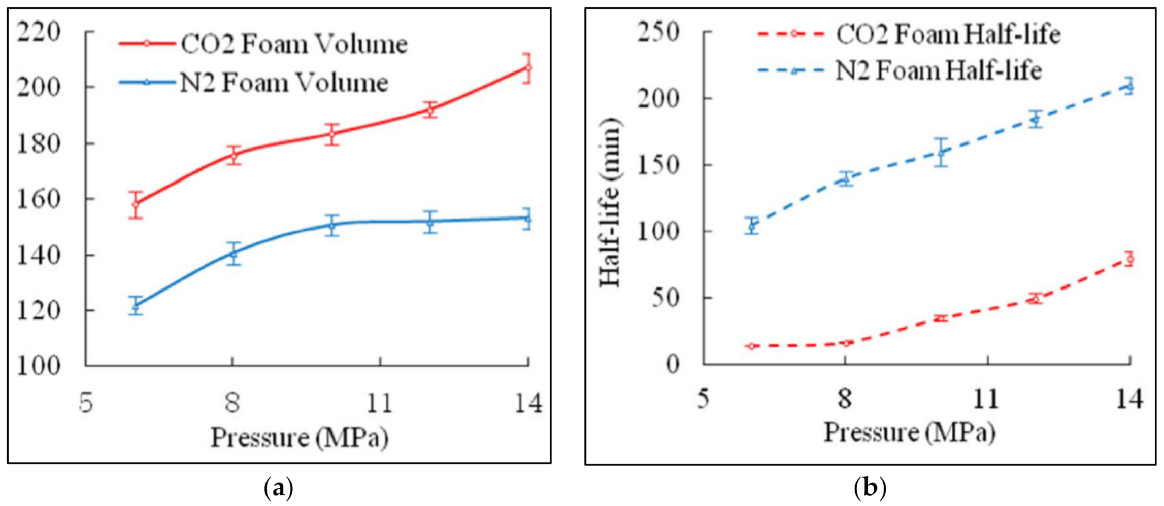
2.2.1. Effect of Pressure on Foam Rheology

The increase in pressure causes the viscosity of foam to increase [18,21,47,53]. A general explanation of the elevated viscosity is that the pressure rise decreases the bubble size, which in return causes the lamella to become “thinner and larger”, thus making it harder for fluid to flow [21,53]. Furthermore, since foam consists of a compressible gas, it can be significantly affected by a pressure change [50].
High pressure causes the effective viscosity to be higher, as shown in Figure 7 below [53]. This study tested the foam’s effective viscosity against the pressure of 10, 15 and 20 Mpa using the foam of 85% quality and foaming agent of 0.67% fraction in the liquid CO2, besides being conducted at the temperature 20 °C.The graph also shows that the apparent viscosity of the foam decreases with increasing shear rate, which indicates the shear thinning behavior. The researchers also deduced that the viscosity of the foam would be higher in the field application as the pressure is higher [53]. However, this deduction is debatable as there will be a negative drawback on the viscosity due to the high temperature in the formation. Moreover, the lamella can potentially rupture in an extremely high-pressure condition [21]; although the term “extremely high pressure” is not adequately quantified.
Valko and Economides (1992) [54] introduced a modification to power-law to consider the effect of gas compressibility due to the pressure drop in a pipe. They found out that for foam with quality above 70%, the pressure drop in a very large pipe may alter foam quality due to gas expansion. The equation is as follows:
τ ε = K ( γ ε ) n
where τ is the shear stress, γ is the shear rate, τ o is the yield stress, K is the consistency index, n is the flow behavior index and ε is the specific volume expansion ratio, which is the density ratio of foam to liquid which changes with pressure [50].
A recent research study introduces the idea of a primary and secondary effect of pressure on foam rheology. The primary effect occurs when the increase in pressure changes the foam quality, affecting the viscosity. Whereas the secondary effect is observed when the pressure increases, the foam quality is maintained. This is achieved by infusing pressurized gas into a fixed foam volume when the pressure is increased, and the system’s temperature is kept constant. This study highlights the significance of the secondary pressure effect by varying the pressure at 1000, 2000 and 3000 psi (6.9–20.7 MPa) while the foam quality is kept constant at 55%. The experiment is repeated for foam quality of 65% and 75%, and the result is shown in Figure 8. The overlapping points in the rheogram graph indicate that the increase in pressure does not affect foam rheology given that the foam quality is kept constant [55].
Overall, the effect of pressure on foam rheology is a sophisticated subject, mainly because of foam’s duality and non-Newtonian behavior. Hence, more holistic research that considers real downhole conditions or even a very high-pressured reservoir should be carried out to fully understand the feasibility of a foam fracturing fluid in a high-pressured setting.

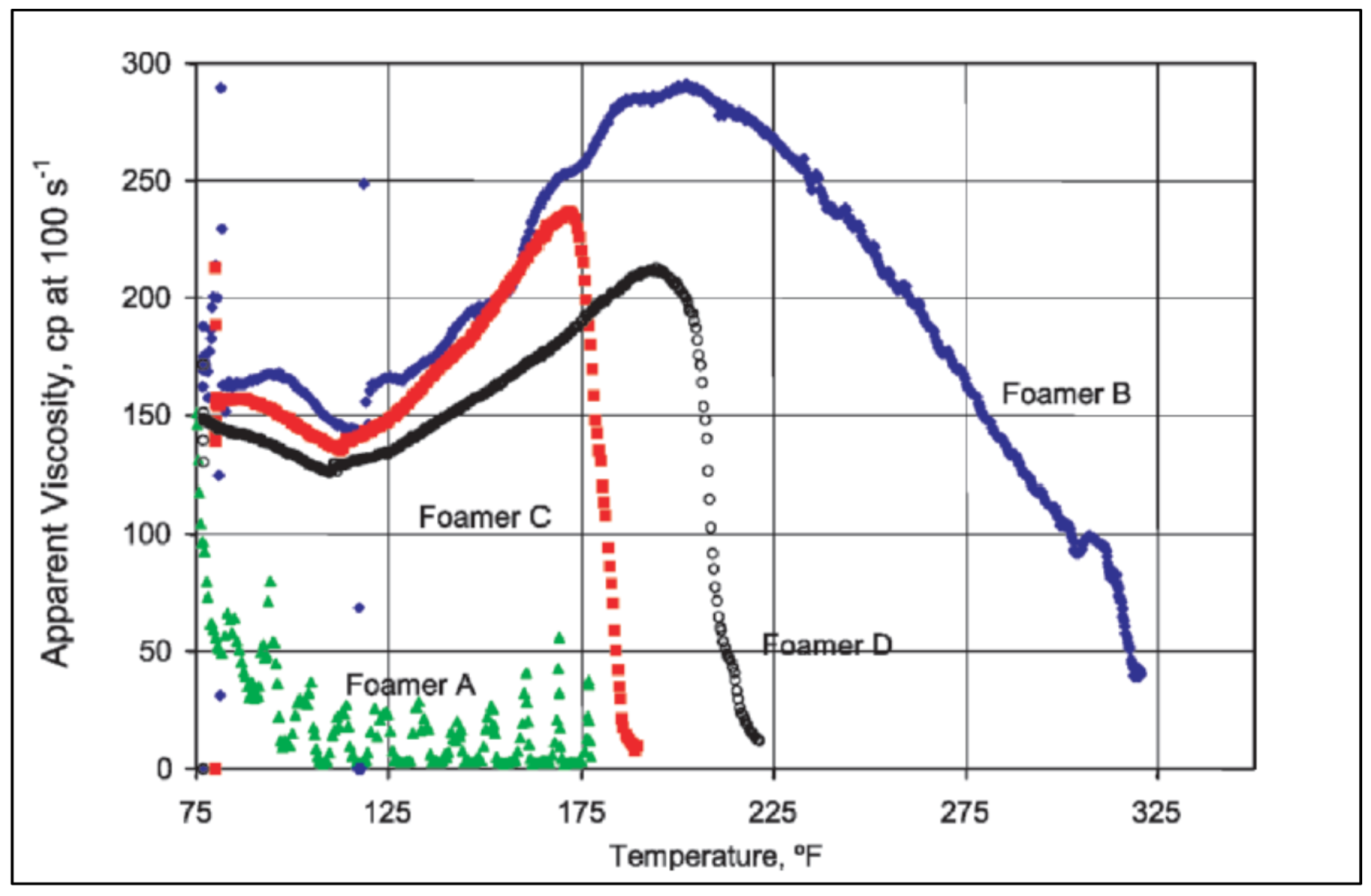
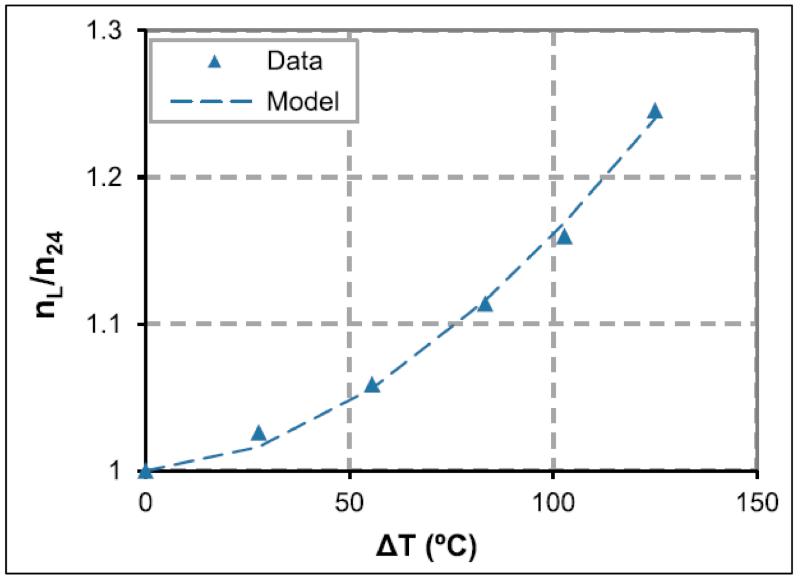
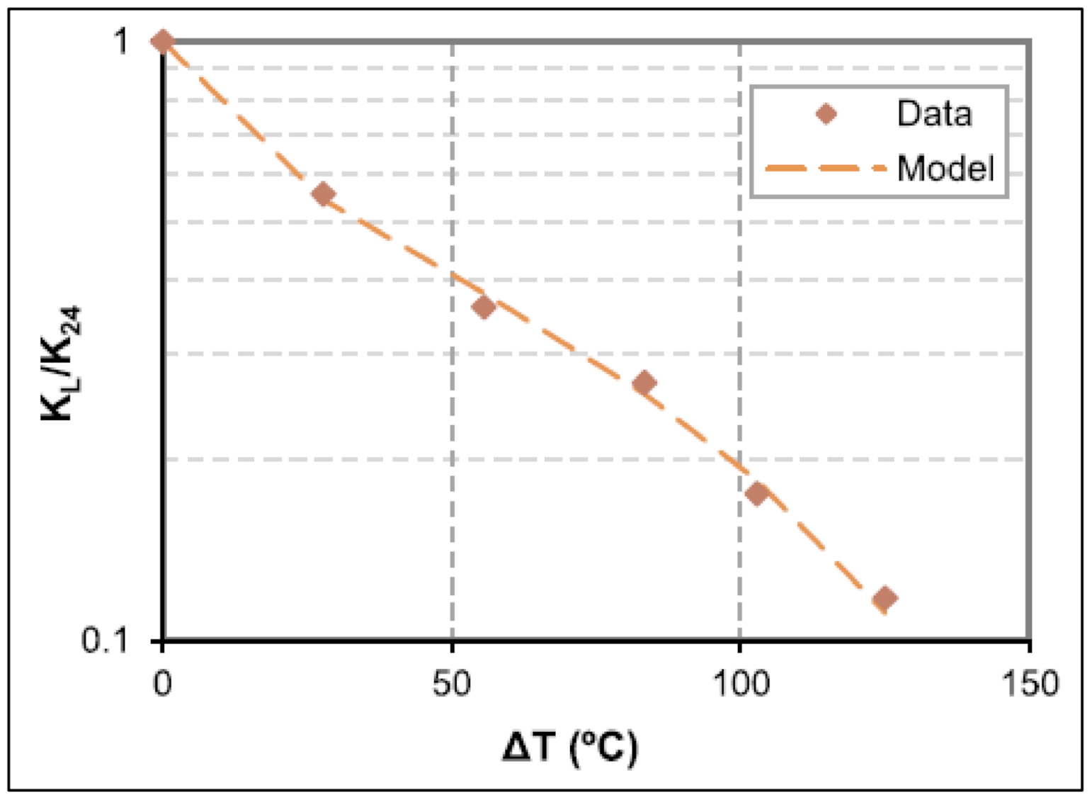
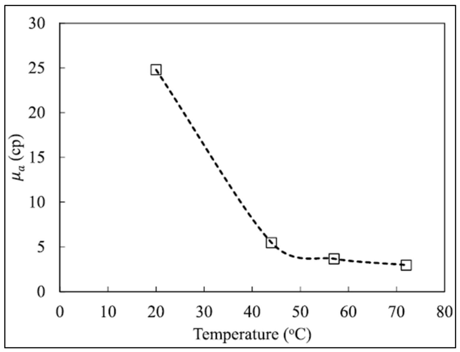
2.2.2. Effect of Temperature on Foam Rheology

In contrast to pressure, increasing the temperature would negatively affect foam rheology. This is exemplified by multiple researchers, whereby it is evident that the increase in temperature causes the foam viscosity to decrease [29,51,56]. In addition, elevated temperature leads to thermal thinning of foam lamella and escalation of the drainage process, thus, lowering the shear rate and viscosity [21,51]. Moreover, the surfactant used in foam may experience high adsorption rate when exposed to elevated temperatures [56]. However, this effect can be prevented by the adding surfactant and gelling agents to stabilize the foam for field application [51,52].
A systematic study conducted by Hutchins and Miller in 2003 [29] evaluated the foam behavior regarding its “time-dependent properties” under dynamic conditions. All of the tested base fluid consists of 1000 gal of water with 40 lbm of guar and 70% initial quality of CO2. Base foam characteristics for each of the fluid are shown in Table 1.
Initially, the foam is at 24 °C and 1100 psi (7.5 MPa). The result in Figure 9 shows that as the temperature increases, the viscosity decreases up to a temperature of about 46 °C. However, since the apparatus only allow a pressure of up to 2000 psi (13.78 MPa), foam in the rheometer need to be withdrawn by piston action to allow the temperature to keep increasing while the pressure is maintained at maximum. As a result of the piston action, the foam quality increases, explaining the increase in viscosity. Nevertheless, the coefficient of thermal expansion for CO2 is low above 93 °C thus keeping the quality almost constant, leading to the decrement in viscosity with the increase in temperature [29].
Furthermore, the correlation between the temperature and foam viscosity can also be demonstrated by Arrhenius equation [53]:
η = A   e x p E f R g T
where A indicates a constant value, Ef is the fluid activation energy, Rg is the constant for molar gas, while T denotes the absolute temperature. Based on this equation, the rise in the temperature will cause the viscosity to decrease [53].
Moreover, at a temperature above 304.26 K (31 °C) and pressure above 1070 psi (7.3 MPa), CO2 exists in a supercritical state where CO2 based foam fluid is not considered as foam [53]. Ahmed et al. (2017) [57] claims that supercritical CO2 is capable to dissolve water. For the case when brine is used as the base fluid, the use of supercritical CO2 may absorb water, thus leaving salt residue that can clog the porous media and consequently hinder production [21].
A study conducted by, Sinha et al. (2019) [51] also demonstrates the effect of temperature on fluid flow behavior and consistency index. In their study, the flow behavior and consistency index are normalized relative to foam behavior at 24 °C, and the results are shown in Figure 10 and Figure 11. The increment in fluid flow behavior with temperature indicates reduced shear thinning behavior, whereas the decrease in consistency index shows the sensitivity of the base fluid towards viscosity. This effect is more significant for foam with intermediate quality (30–50%), whereas foam with below 30% quality and above 50% quality is similarly influenced by temperature.
All of the literature findings indicate that the increase in temperature conditions causes a detrimental effect on foam viscosity. However, most studies have a narrow testing window regarding temperature in their experimental research. For instance, Hutchins and Miller (2003) [29] and Sinha et al. (2019) [51] studied foam rheology up to 300 °F while Fu and Liu (2020) [56] experiment is limited to only 72 °C, which is much lower than the temperature of a HPHT reservoir. Moreover, most studies kept the pressure constant while increasing the temperature, although the temperature and pressure in the wellbore will increase simultaneously. Therefore, question raised in this article is which effect is more profound toward influencing foam rheology: pressure or temperature?

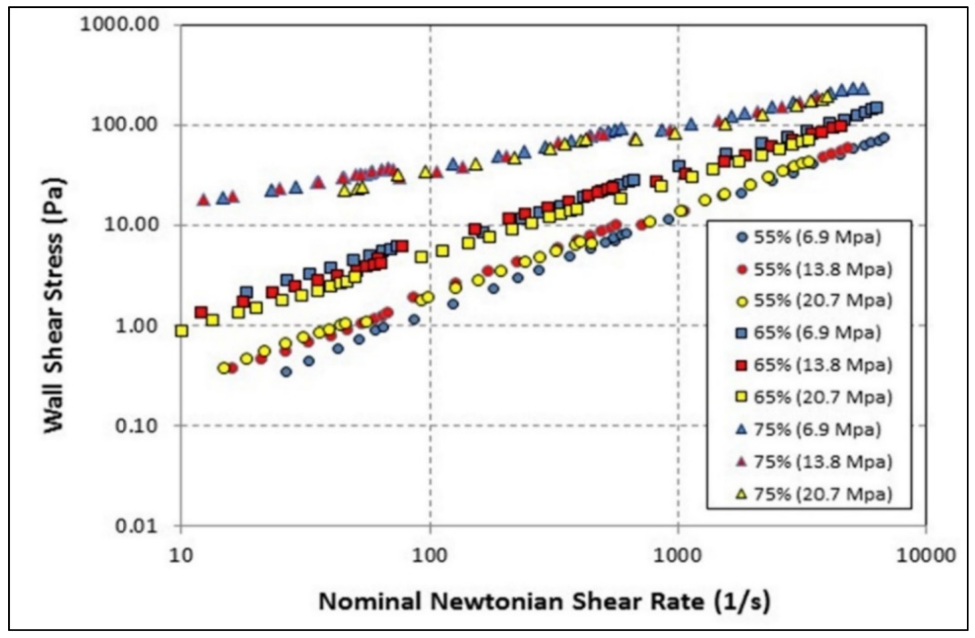
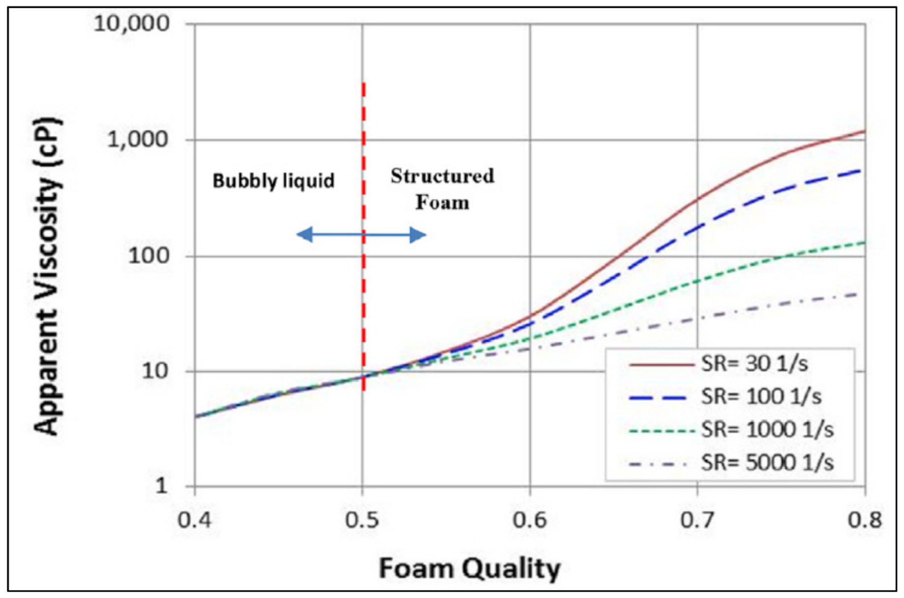
2.2.3. Effect of Foam Quality on Rheology

A considerable number of studies recognize the significant effect of foam quality on its rheology. These studies even suggest that foam quality is the most critical parameter influencing foam flow behavior [39,55]. Prior research claims that as foam quality increases, foam viscosity will increase up to a certain breaking point where the foam viscosity will decrease drastically [21,51,58]. This trend is depicted in Figure 12 below [51].
As quality increases, the number of bubbles in foam also increases, which motivates more collision and friction between them, thus causing the increase in viscosity [58]. Meanwhile, when the foam becomes dry, the bubble becomes unstable and collapses, leading to a drop in viscosity [21]. The breaking point at which the viscosity starts decreasing ranges between 90 to 97% [51]; whereas for supercritical CO2 it is at around 85% [57]. As a result, the aqueous foam may transform to mist and lose its proppant transportability at around 95% quality [58]. Other than that, foam with very high quality also exerts high friction pressure during pumping. Hence, it is vital to identify the optimum foam quality for field application.
Mitchell (1971) established a mathematical model to estimate foam viscosity as a function of the base liquid viscosity and foam quality [55].
η F = η L 1 + 3.6 Γ   if   Γ 54 %
η F = η L 1 Γ 0.49   if   Γ > 54 %
where η F is the foam viscosity, η L is the base liquid viscosity and Γ is the foam quality [55].
Mitchell (1971) classifies Equations (6) and (7) at 54% quality because low-quality foam behaves according to Newtonian flow, but high-quality foam exhibits non-Newtonian behavior [18]. This also explains why the yield stress is more significant for foam with higher quality, as yield stress is an important aspect of a non-Newtonian fluid [51,55]. Another profound aspect relating to the non-Newtonian behavior of high-quality foam is the foam structure, where the non-Newtonian fluid is more rigid than Newtonian fluid. As a result, the foam becomes more rigid at around 63% [55].
Hence, from Figure 12, we can observe that viscosity rapidly increases at around 63%. This is because, at that point, the foam becomes more well-structured, making it harder for fluid to flow [51].
In support of Mitchell’s theory stated above, Akhtar (2018) [55] investigated foam behavior toward viscosity and shear rate at different qualities. The result is shown in Figure 13, which supports the claim that foam of low quality behaves similarly to a Newtonian fluid. As demonstrated in the figure, under 50% quality, there are no changes in viscosity in relation to the shear rate. As the quality exceeds 50%, foam displays shear-thinning behavior where apparent viscosity decreases with increasing shear rate. However, throughout the analysis, conducted by multiple researchers, there are some differences in the turning point or the breaking point value, which can be attributed to the different base fluid used, surfactant concentrations or foam generation method.
In summary, two profound effects on rheology emerge from the literature reviewed. First, the increase in foam quality results in higher viscosity up to a certain point above which the viscosity will decrease. Secondly, there is a turning point in foam quality where fluid behavior transforms from Newtonian to non-Newtonian. The previous section also discovered that the change in pressure might affect foam quality, thus affecting rheology. Therefore, a greater focus on foam quality while assessing another parameter should also be applied as foam quality has a significant effect on foam rheology.

3. Foam Stability

Apart from rheology, foam efficiency is also commonly characterized by foam stability. Foam is principally unstable as it is made up of two dispersed phases of liquid and gas that will naturally separate into their respective phases once formed, consequently lowering the viscosity [24]. Most researchers usually evaluate foam stability by its half-life. As stability is described as the ability of the foam to preserve its properties, half-life indicates the time taken for the foam to lose half of its initial volume [59]. In field applications, the half-life of foam for a fracturing operation should last longer than the time taken for the proppant to penetrate the targeted zones. Therefore, to increase the half-life or slow down the foam from rupturing, it is crucial to first understand the factors that lead to foam destabilization: drainage, coarsening, and coalescence. [45]. These processes occur interdependently, with drainage as the major mechanism that destabilizes the foam [24].

3.1. Foam Drainage

Drainage is caused by the flow of liquid towards the bottom due to gravity, thus separating the liquid from gas in foam [59]. In this case, the liquid is drained from networks of plateau borders by gravity and pushed down by capillary action along the lamella [24], as shown in Figure 14 [35]. This is because the plateau border at the intersections of liquid films exerts relatively less pressure than the lamella. Due to the different pressure profiles, liquid from the lamella drains into the plateau border in the direction of gravity [36]. Although multiple researchers have developed a model that assumes that drainage is solely because of fluid flow in plateau border, the models show inconsistencies with actual data, which indicates an additional factor that induces drainage [24]. Other than that, Weaire et al. (2016) [48] also propose that liquid drainage may initiate the collapse of foam as it gradually changes the dynamic of foam before yield stress is achieved. Therefore, one of the fundamental steps to increase foam stability is to slow down the drainage process, which is achievable by either increasing the liquid viscosity or surface elasticity [36].

3.2. Foam Coarsening

Foam coarsening is also commonly known as Ostwald ripening or disproportionation, which is the diffusion of gas between adjacent bubbles [60]. This process is driven by Laplace pressure which is a function of surface tension and the radius of bubbles [45]. Foam drainage reduces the liquid fraction in foam and causes the thinning of the liquid film [30], which eases the gas diffusion process [24]. Since gas diffusion usually occurs from small bubbles to larger bubbles, coarsening causes large bubbles to expand which alter the size distribution of bubbles thus accelerating drainage rate. Accordingly, the coarsening process can be slowed down by reducing the heterogeneity of the gas bubbles sizes [36].

3.3. Foam Coalescence

Coalescence is the process where the neighboring bubbles combine, thus breaking open the lamella leading to bigger bubble size [59]. Among the 3 processes, coalescence is the least understood mechanism [24]. Coalescence differs from coarsening because when bubbles coalesce, gas escape from the foam formation, which may reduce the gas fraction, whereas in coarsening, since the gas is just diffused from one bubble to another, no gas is lost [59]. The difference in the texture of bubbles due to the two processes is shown in Figure 15.
There is also a similarity between coarsening and coalescence where both processes could occur efficiently in the dry foam where the film is thin. Therefore, surfactants or nanoparticles are used as a medium to inhibit foam coalescence. Surfactants, having hydrophilic and hydrophobic components, arrange themselves at the bubble interface so that the film can “mend itself” [35]. When a point on the surface of the bubbles becomes relatively thinner, the spot will have a bigger surface area, reducing the surfactant concentration at the spot, thus allowing the surfactants nearby to fill up the space [31,42]. This phenomenon is called the Gibbs-Marangoni effect, which is illustrated in Figure 16 [24].

3.4. Factors That Affect Foam Stability

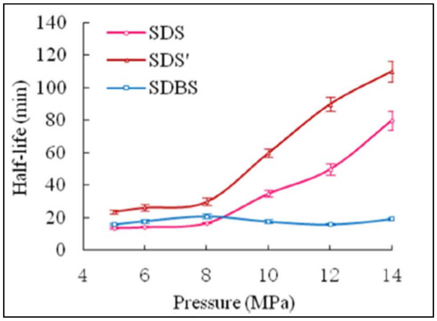
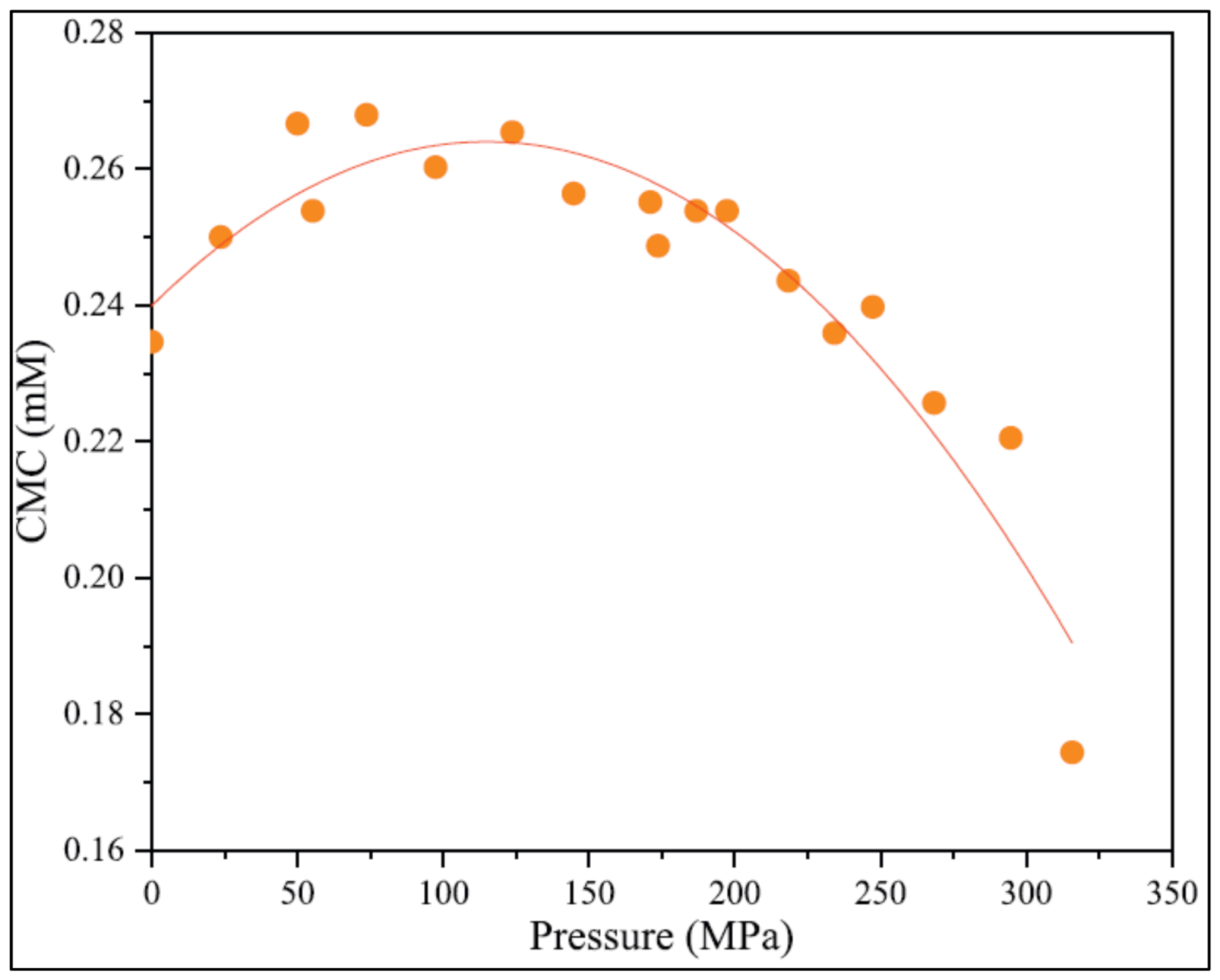
3.4.1. Effect of Pressure on Foam Stability

As previously established in Section 2.2.1, the increase in pressure indirectly raises foam viscosity as gas compressibility changes the foam quality. In relation to stability, the increase in pressure stabilizes the liquid film, resulting in higher foam viscosity [21]. Furthermore, the increase in viscosity can also be attributed to the homogeneity of the bubble size, which can be induced by higher pressure [53]. Therefore, as pressure increases, the average bubble size will become smaller, and more well-distributed, which will enhance foam stability besides hindering the coarsening process.
Wang (2017) [61] studied the effect of pressure on foam stability. The experiments investigate the performance of the different type of surfactants with different concentrations against increasing pressure at 100   o C . The detailed properties of the anionic surfactants studied is tabulated in Table 2, whereas the results are shown in Figure 17. Apart from foam with sodium dodecyl benzene sulfonate (SDBS) surfactant, the increase in pressure generally elongates the half-life of foam. This is attributed to the low hydrophilic-lipophilic balance (HLB) value of SDBS surfactant, which desensitized the foam to pressure. Wang et al. (2017) [61] also proposed that pressure change can modify the “hydrophobic and hydrophilic” balance of surfactants which will influence lamella’s stability. However, the study offers no further explanation for how raising pressure alters the affinity balance.
Furthermore, critical micelle concentration (CMC), which is the minimum surfactant concentration needed to form micelle is also affected by pressure. From Figure 18, CMC value increases when pressure is less than 50 MPa which signifies more surfactants needed for optimum foam performance in a relatively low-pressured reservoir hence, requiring higher cost [24].
Previous studies reported that CO2 tends to become more hydrophilic in high pressure, thereby is less stable than N2 [61]. As observed in Figure 19a, CO2 foam shows volume increment with pressure whereas, at around 10 Mpa, the N2 volume remains constant as pressure increases indicating the sensitivity of CO2 towards pressure change. On the other hand, since N2 foam volume remains constant above 10 Mpa, it indicates N2 foam stability, which is also supported by Figure 19b, which shows that N2 foam can sustain five times longer than CO2 foam in an isothermic condition with increasing pressure [61].
Despite having a higher stability, the study of N2 in foam fracturing fluid is still not as prevalent as CO2. Moreover, no known research investigates whether the positive effect of pressure on foam stability can be directed to the pressure increase itself or primarily due to the fluid compressibility. Likewise, there is still insufficient research on foam stability at HPHT conditions for foam rheology.

3.4.2. Effect of Temperature on Foam Stability

The thermal instability of foam remains one of the most significant limitations with the use of foam as fracturing fluid. A large number of the existing literature have studied the adverse effect of temperature on foam stability [39,46,56,61]. High temperature is detrimental to foam stability due to multiple factors. Firstly, high temperature increases kinetic energy which causes gas expansion, which narrows the lamella, causing the drainage process to be accelerated [18,21]. A study by Kapetas et al. (2016) [46] also shows that the drainage rate is fastened with increasing temperature. Moreover, at high temperatures, foam texture is relatively coarser with a larger bubble size distribution [21]; which is a favorable condition for coarsening. Coarsening is also anticipated to occur at higher temperatures because high temperature increases lamella’s permeability, which eases gas diffusion [46]. Additionally, coarsening and coalescence rate increases with temperature fluctuations, which may also cause the formation of holes in the liquid film, which may cause the lamella to rupture and increase bubble coalescence [21]. Figure 20, demonstrates the effect of temperature on CO2 apparent viscosity [56].
As a result of high drainage and coalescence rate, high temperatures also significantly lower foam apparent viscosity [21,56]. The reduction in foam viscosity will negatively affect foam stability. Fu and Liu (2020) [56] studied the effect of temperature on the foam viscosity and stability. They reported that with increasing temperature, foam apparent viscosity, which is initially at 24.8 cp rapidly decreases up until 43 °C; where then the viscosity gradually decreases to only 3 cp as depicted in Figure 20. They also discovered that the half-life of CO2 foam developed at 72 °C did not even last for 1 h.
The study conducted by Wang et al. (2017) [61] supports the theory that temperature rise will destabilize foam, although multiple different surfactants are used. The surfactants’ details are tabulated in Table 2, whereas the results are shown in Figure 21 [61]. Although all of the surfactants studied react negatively with the increase in temperature, the foam with SDS’ shows better stability than the other surfactants where the half-life of SDS’ exceeds one hour at a temperature of 120 °C. SDS’s surfactant’s performance is attributed to the high number of HLB, which enhance the foam tolerance toward temperature. Moreover, the study concludes that anionic surfactants have higher stability and tolerance toward high temperatures than non-ionic surfactants.
The poor performance of foam at high temperatures may also be attributed to the thermal degradation of surfactants and its tendency to adhere to the rock formation at high temperatures [56]. Plus, according to Zhou et al. (2020) [24] polymers will usually degrade at a temperature above 85 °C. Consequently, polymer residue may plug the porous media, thus damaging the formation [18]. Hence, more recent studies have proposed some alterations to the conventional surfactant-based foam system, such as nanomaterials or enhanced surfactants to improve foam stability under reservoir conditions.

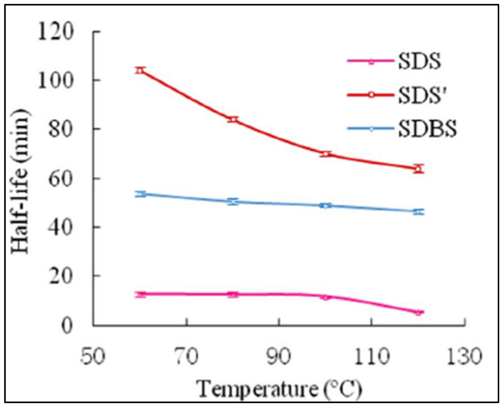
3.4.3. The Effect of Surfactants on Foam Stability

The selection of surfactant type and concentration is essential to ensure the efficiency of a fracturing process. This is because different surfactants have different compatibility in different conditions. For instance, an anionic surfactant can hydrolyze well at high temperatures and does not adsorb well to minerals with a negative charge [24]. On the other hand, cationic surfactants are very stable and soluble in a condition with high temperatures and salinity. Besides, it can easily be absorbed in the formation. In addition to this, both surfactants can alter surface tension and wettability depending on their concentration [14].
Optimization of surfactant concentration is another crucial task to ensure foam stability. Generally, low surfactant concentration will produce unstable foam and the increase in concentration may viscosify the foam better and increase the stability of foam film [21]. Higher surfactant concentration may also increase the network of micelles thus affecting the surfactant packing structure. Moreover, when surfactant concentration is too high, it could slow down the Gibbs-Marangoni effect, yielding lower surface elasticity, consequently lowering overall foam stability [37,42]. Therefore, selecting the right surfactant with an appropriate concentration is essential for optimizing foam stability.

4. Nanoparticle as a Foam Stabilizing Agent

In recent years, there has been a rising number of studies that recognize the potential of nanoparticles as an additive in foam formulation to stabilize foam under reservoir condition. As previously discussed, the use of surfactants alone is insufficient for maintaining foam stability under high temperatures. In contrast, the addition of conventional polymer is inefficient as it may degrade and cause pore plugging [24]. On the other hand, experimental results by several researchers show that the use of nanoparticles in the foam is known to improve overall foam stability under high-temperature condition [4,47,56]. Therefore, this section will review the application of nanoparticles on foam fracturing fluid and its impact on foam rheology and stability.

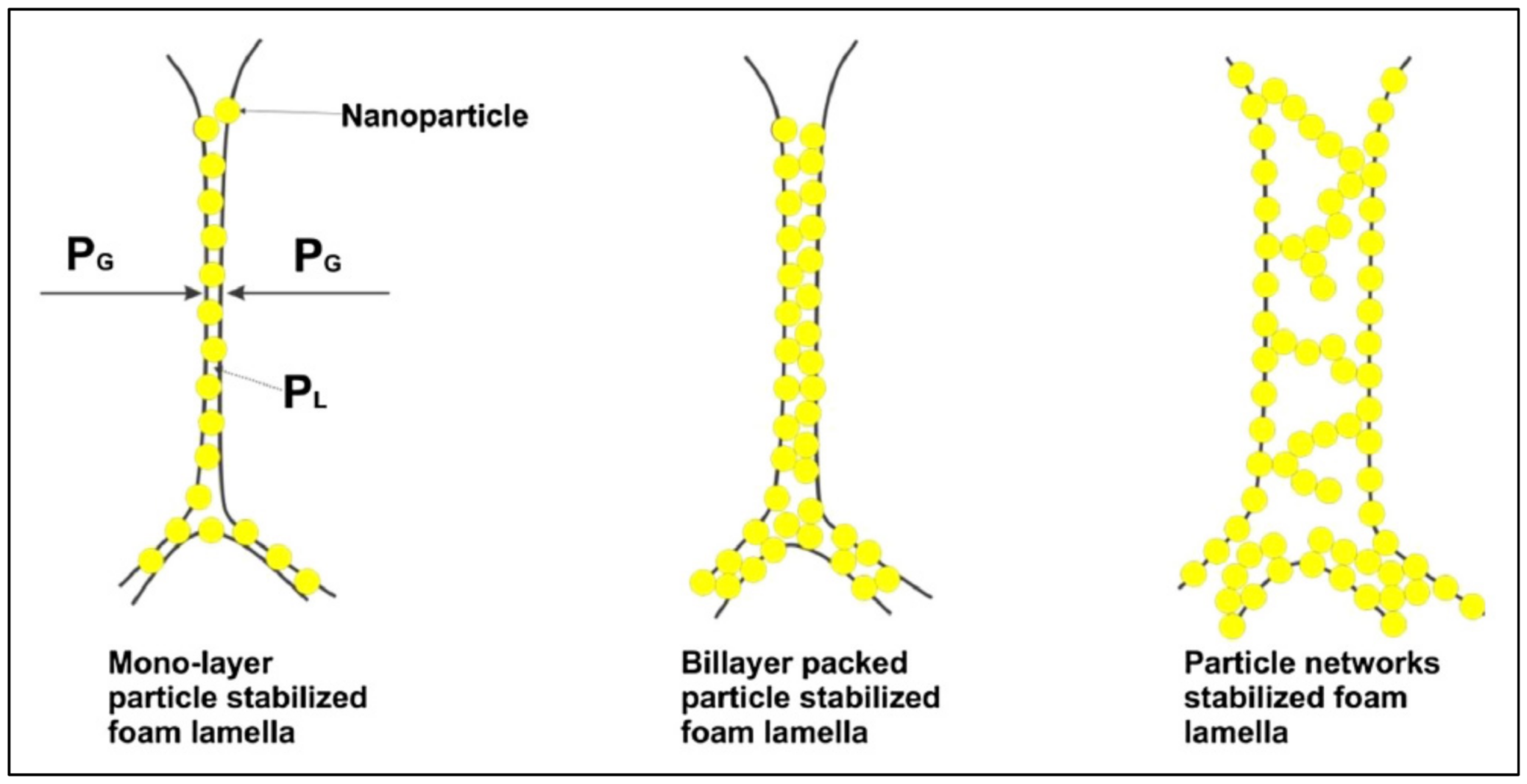
4.1. Mechanisms of Foam Stability

The major mechanisms of foam stability improvement in the presence of the nanoparticles are the adsorption and aggregation of the nanoparticles at the gas-liquid interface of the foam. The aggregated nanoparticles can assemble as a monolayer of bridging particles when positioned as one layer at the interface [20].
Nanoparticles enhance foam rheological properties and stability by adsorbing to foam lamella and forming a steric boundary that prevents gas bubbles from merging [25]. Due to their small size, nanoparticles have a large ratio of surface area to volume, which eases their irreversible adsorption to bubble interfaces. Nanoparticles can adsorb to the bubble surface in three different ways as shown in Figure 22 [4,39], where these arrangements are controlled by nanoparticles concentration in the foam [24]. The monolayer bridging of nanoparticles (a) will form at low nanoparticle concentration whereas as the concentration increases, nanoparticles coagulate and develop a “bilayer of closely packed particles” (b).
Even at low concentration, the monolayer structure, as depicted in Figure 22, can act as the steric boundary, which slows down the drainage, and the structure can be preserved even when the foam film gets thinner [24,56]. Moreover, when the bilayer structure or the particle networks are formed at a higher concentration, the foam stability is improved because the thickness of the liquid film increases beyond the critical rupture, which lowers the tendency for the film to rupture, thus preventing bubbles from coarsening and merging [30]. The nanoparticle networks also serve as additional structural integrity to strengthen the lamella [56].
The effect of nanoparticles concentration on foam stability has also been tested experimentally. Fu and Liu (2020) [56] studied the effect of nanoparticle concentration against the viscosity of CO2 foam with 70% quality, salinity of under 5% NaCl, flow rate of 12 mL/min and temperature of 20 °C. The result of this experiment is demonstrated in Figure 23. [56]. In this study, the investigated shear rate range is between 1440 s−1 and 4400 s−1, in which the effect of the improved foam texture dominates.
Based on the results, it is evident that an increment in nano-silica concentration enhanced the foam apparent viscosity up to a certain point. The viscosity enhancement is credited to the fact that a high number of nanoparticles motivates the development of liquid lamella besides increasing interfacial tension gradient at the bubble interface. Plus, the interfacial strength provided by nanoparticles also enhances the viscoelasticity of the liquid. However, there exists a critical point at which the increase in concentration does not help with enhancing foam performance as the viscosity plateaued. For this study, the critical nanosilica concentration is 5000 ppm [56]. Hence, it is important to understand the optimum concentration of nanoparticles to prevent excessive cost for the fracturing process.
Moreover, the correct utilization of nanoparticles should also be understood as the application of nanoparticles alone would not be able to stabilize foam under high temperatures [24]. Multiple works of literature highlight the synergistic effect of surfactants and nanoparticles to deliver promising performance under harsh conditions. For example, a surfactant can alter nanoparticles’ wettability and gas-liquid interfacial tension, which boosts nanoparticles’ ability for foam generation. Furthermore, the reaction between nanoparticles and surfactants may also prevent surfactants from absorbing on rock formation, besides enhancing the hydrophobicity of nanoparticles which vary according to the type of surfactants. For instance, silica nanoparticles, which are the most commonly used nanoparticles, is negative in solutions hence is better complemented with the use of cationic surfactants [24,62]. Contrarily, other researchers claim that foam stability can only be enhanced by electric repulsion of similarly charged particles as an oppositely charged surfactant and nanoparticles may promote thinning of lamella and bubbles coalescence [25]. Therefore, further research is required to understand the synergistic reaction between nanoparticles and surfactants fully.
Tuan et al. (2022) [38] studied the effects of three types of surfactants with varying concentrations on the properties of silica nanoparticles (SNP) and on the stability of nano-stabilized foams at ambient and elevated temperatures. The experiments involved the zeta potential, particle size and contact angle measurements of SNP in surfactant solutions and the foamability and bulk static stability tests. The results showed that among three surfactant types, cationic surfactant had some unique impacts on SNP, such as converting the surface charge, promoting particle aggregation, and increasing the hydrophobicity of SNP. The aggregation behavior and hydrophobization of SNP were found to delay liquid drainage and positively affect the foam stability. At elevated temperatures, SNP in surfactant dispersions was observed to have a lower magnitude of zeta potential and larger particle sizes. Compared with ionic surfactants, non-ionic surfactants demonstrated considerably smaller effects on generating and stabilizing nano-foams. The electrostatic attraction between cationic surfactant and SNP at sufficient surfactant concentration promoted higher foam stability than the electrostatic repulsion between anionic surfactant and SNP
Fei et al. (2017) [39] systematically analyzed the performance of foam which constitutes nanoparticles, a conventional anionic surfactant and worm-like micelle (WLM) which is formed from zwitterionic surfactants [39]. Zwitterionic surfactant is a type of surfactant that consists of both cationic and ionic charges [24]. As previously shown in Figure 2, as the concentration of zwitterionic surfactants reaches above CMC, micelle can be formed in, which it will transform to WLM with the aid of electrolyte [39]. Among the advantages of zwitterionic surfactant is that it is more environmentally friendly than other types of surfactants and has higher thermal resistance [24,39,45].
In this study, a comparison between the half-life of foam containing 3–5 wt% of zwitterionic surfactant, specifically, erucyl amido-propyl betaine (EAPB) is investigated along with EAPB in presence of nanoparticles. The half-life of the foam is studied under a free drainage condition with the temperature set at 90 °C. The results of their study are shown in Figure 24. Essentially, in all cases, the addition of nanoparticle elongates the half-life of foam especially for 3 wt% EAPB concentration, where the nanoparticle enhances the foam stability by 31%. In addition to this, the results also show that the increment in EAPB concentration also improves foam stability [39].
The positive effect of nanoparticles is attributed to the increase in the foam viscosity that slows down the drainage time. Other than that, the drainage time is also increased by the presence of “cork formation” due to the aggregation of nanoparticles in the plateau border, which obstruct the passage for the liquid to flow thus reducing the available pathway for liquid drainage as depicted in Figure 25 [39].
Apart from half-life, foam stability can also be observed visually by improving foam microstructure. Lv et al. (2015) [47] compared the stability of SDBS foam against SDBS foam with silica ( S i O 2 ) nanoparticles addition over a 7-h. As observed in Figure 26, the structure of SDBS foam becomes coarser with irregular bubble sizes after 7 h, while the bubbles in S i O 2 /SDBS foam remain spherical in shape with thick liquid films. This phenomenon is associated with the permanent adsorption of nanoparticles on the bubble interface, which improves bubble’s viscoelasticity thus preserving foam stability [24].

4.2. Nanoparticle Effect of Foam Rheology

While some research has been carried out on foam stability, there is much less information available on the effect of nanoparticle on the rheology of foam fracturing fluid. It has been previously established that the use of nanoparticles can enhance foam viscosity [4,39,45,47]. Fei et al. (2018) [30] developed a chart shown in Figure 27 to visualize the performance of foam of low and high viscosity, with and without nanoparticles, against foam quality. The increase in viscosity with quality in the “free drainage” region is due to the interaction between particles, which will be boosted as the drainage occurs and gas fraction increases. However, as foam quality increases, coarsening and coalescence happen more frequently, thus reducing foam viscosity. The addition of nanoparticles can increase the foam viscosity in the drainage region besides maintaining the foam viscoelasticity in the coarsening and coalescence region, resulting in an overall higher viscosity and proppant-carrying ability compared to foam without nanoparticles.
Regarding the nanoparticle-stabilized foam behavior under stress, there are still contradicting opinions from multiple literatures. Similar to foam property without nanoparticles, Fei et al. (2017) [39,45] reported that EAPB foam with 0.8 wt% silica nanoparticles exhibit shear-thinning behavior where apparent viscosity decreases with increasing shear rate. In contrast, research by Lv et al. (2015) [47] indicates that the nanoparticle-stabilized foam in their study shows shear thickening behavior where the n value obtained from foam with different qualities are all more than 1. On the other hand, Xiao, Balasubramanian and Clapp (2017) [49] studied the foam rheology of carbon dioxide foam with anionic surfactant and S i O 2 nanoparticles. Ten types of foam with different compositions of nanoparticles, gas fractions, anionic surfactants and salt were analyzed under varying shear rate. Based on their findings, some foams exhibit shear thinning or shear thickening behavior, while 1 of the foams that contains nanoparticles, surfactants and 2 wt% of salt shifts from shear thinning to shear thickening when quality is increased from 50% to 60% [49]. However, the study did not determine the underlying cause of these outcomes. Since foam of low quality behaves according to Newtonian flow, [55] the use of power-law to model foam with 50% quality may produce discrepancy in the results.

4.3. Proppant Transportability of Nanoparticle-Stabilized Foam

The ability to suspend proppant to the targeted zone is one of the most important characteristics of a fracturing fluid. Figure 27 [47], indicates that as foam quality increases in the drainage-dominated region, proppant transportability of foam increases and reaches a peak before declining due to coarsening and coalescence. Ideally, the foam should have high viscosity, so the time for the foam to reach the coarsening region can be delayed, thus maintaining the proppant suspension ability [30]. Based on their research, proppant addition causes the presence of a “transition regime”, which delays the foam from experiencing coarsening and coalescence.
Furthermore, Lv et al. (2015) [47] also compare the proppant settling velocity of SDBS foam with and without nanoparticles at increasing temperatures. The result shown in Figure 28 indicates that proppant will settle faster from foam without nanoparticles. Moreover, for S i O 2 /SDBS foam, the slope of the graph is lower than SDBS foam, indicating a lower sensitivity toward the change in temperature. These results are due to the irreversible adsorption of nanoparticles which roughen the surface of the bubbles and cause difficulty for proppant to slip through the bubble surfaces, as depicted in Figure 29 [39]. Additionally, the adsorption also causes higher “dilational viscoelasticity”, thus providing higher resistance for proppant to rupture the bubbles [47].

5. Conclusions

The conventional water-based fluid poses challenges, especially in water-sensitive formations such as shale reservoirs, as it may cause swelling and formation damage. Hence, foam fracturing fluid has been gaining attention due to its potential to be a more environmentally friendly, “waterless” fracturing fluid option. This review has studied the applicability of foam fracturing fluid in HPHT reservoir conditions by focusing on foam rheology and foam stability. In addition, the use of nanoparticles to overcome foam limitations is also discussed. The following are the major findings, possible shortcomings, and the gaps in the literature that should be addressed by future research:
  • Foam viscosity appears to increase with increasing pressure and decrease with increasing temperature. However, the apparent increase in viscosity due to pressure is attributed to the expansion of gas in the foam, which increases gas quality, thus causing increased viscosity;
  • The increase in foam quality causes the foam viscosity to continually increase up to a breaking point. Then, the foam becomes too dry, causing the viscosity to start rapidly declining. Hence, since the increase in pressure induces the increase in gas quality, the question arises whether there exists a point in pressure that will also become a breaking point that leads to a rapid decline in viscosity;
  • Foam rheology is a complex parameter because low-quality foam behaves as a Newtonian fluid, whereas foam with high-quality exhibits non-Newtonian behavior in which it possesses yield stress. However, the point in foam quality in which foam transforms from a Newtonian to non-Newtonian fluid could not be easily pinpointed as experiments conducted by multiple works of literature use various compositions of foam fracturing fluid, resulting in different outcomes;
  • The most significant limitation with applying foam fracturing fluid is its instability under high temperatures. Hence, the addition of nanoparticles to foam formulation has been proposed by several authors to solve this problem;
  • Many studies have proven that nanoparticle-stabilized foam shows improved resistance toward heat compared to conventional foam. However, most of the studies only tested the foam stability up to 90 °C when the temperature of the HPHT environment is at least 150 °C;
  • There is still contradicting theories on the ideal combination of nanoparticles and type of surfactants. Further investigation is strongly recommended to fully utilize the synergistic effect of nanoparticles and surfactants. In addition to this, numerous research to date tends to focus only on the stability of nanoparticle-stabilized foam rather than the rheology. Yet, within the limited number of available studies, inconsistencies exist regarding nanoparticle-stabilized foam behavior toward stress. Therefore, future research should strategically examine the factor that produces the diversity of results regarding this matter;
  • The findings presented in this paper are based on experimental data and no field applications. Other than that, some other factors that affect foam rheology and stability, such as salinity, were not discussed.
The main conclusion that can be drawn from this review is that although nanoparticle-stabilized foam fracturing fluid shows enormous potential to become an efficient and environmentally safe fracturing fluid, extensive research should still be carried out to ensure the feasibility of this technology under real reservoir conditions.

Author Contributions

Investigation, M.E.G.P. and S.W.M.; resources, M.E.G.P. and S.W.M.; writing—original draft preparation, S.W.M.; writing—review and editing, M.E.G.P.; supervision, M.E.G.P. All authors have read and agreed to the published version of the manuscript.

Funding

This research received no external funding.

Data Availability Statement

The data used in the model development and evaluation were obtained from open literature, and the references are provided in the Reference section.

Conflicts of Interest

The authors declare no conflict of interest.

References

  1. Montgomery, C.T.; Smith, M.B. Hydraulic fracturing: History of an enduring technology. J. Pet. Technol. 2010, 62, 26–40. [Google Scholar] [CrossRef]
  2. Al-Muntasheri, G.A.; Liang, F.; Hull, K.L. Nanoparticle-enhanced hydraulic-fracturing fluids: A review. SPE Prod. Oper. 2017, 32, 186–195. [Google Scholar] [CrossRef]
  3. Gulrajani, S.N.; Nolte, K.; Economides, M. Fracture evaluation using pressure diagnostics. Reserv. Stimul. 2000, 1–9. [Google Scholar]
  4. Fei, Y. Experimental and Numerical Investigation of Nanotechnology on Foam Stability for Hydraulic Fracturing Application. Ph.D. Thesis, Australian School of Petroleum, North Terrace, Australia, 2017. [Google Scholar]
  5. Alotaibi, M.A.; Miskimins, J.L. Slickwater proppant transport in complex fractures: New experimental findings & scalable correlation. In Proceedings of the SPE Annual Technical Conference and Exhibition, Houston, TX, USA, 28 September 2015. [Google Scholar]
  6. Chang, O.; Dilmore, R.; Wang, J.Y. Model development of proppant transport through hydraulic fracture network and parametric study. J. Pet. Sci. Eng. 2017, 150, 224–237. [Google Scholar] [CrossRef]
  7. Jansen, T.; Zhu, D.; Hill, A.D. The effect of rock mechanical properties on fracture conductivity for shale formations. In Proceedings of the SPE Hydraulic Fracturing Technology Conference, The Woodlands, TX, USA, 3 February 2015. [Google Scholar]
  8. Li, N.; Li, J.; Zhao, L.; Luo, Z.; Liu, P.; Guo, Y. Laboratory testing and numeric simulation on laws of proppant transport in complex fracture systems. In Proceedings of the SPE Asia Pacific Hydraulic Fracturing Conference, Beijing, China, 24 August 2016. [Google Scholar]
  9. Liu, Y.; Leung, J.Y.; Chalaturnyk, R.; Virues, C.J. Fracturing fluid distribution in shale gas reservoirs due to fracture closure, proppant distribution and gravity segregation. In Proceedings of the SPE Unconventional Resources Conference, Calgary, Canada, 15 February 2017. [Google Scholar]
  10. Shiozawa, S.; McClure, M. Simulation of proppant transport with gravitational settling and fracture closure in a three-dimensional hydraulic fracturing simulator. J. Pet. Sci. Eng. 2016, 138, 298–314. [Google Scholar] [CrossRef] [Green Version]
  11. Yu, W.; Zhang, T.; Du, S.; Sepehrnoori, K. Numerical study of the effect of uneven proppant distribution between multiple fractures on shale gas well performance. Fuel 2015, 142, 189–198. [Google Scholar] [CrossRef]
  12. Zhang, G.; Li, M.; Gutierrez, M. Numerical simulation of proppant distribution in hydraulic fractures in horizontal wells. J. Nat. Gas Sci. Eng. 2017, 48, 157–168. [Google Scholar] [CrossRef]
  13. Speight, J.G. Handbook of Hydraulic Fracturing; John Wiley & Sons: Hoboken, NJ, USA, 2016. [Google Scholar]
  14. Chai, Y.; Li, X.; Jing, D. Application of surfactants in hydraulic fracturing for enhanced. J. Oil Res. 2019, 5, 161. [Google Scholar]
  15. Denney, D. Fluid selection for energized hydraulic fractures. J. Pet. Technol. 2010, 62, 42–44. [Google Scholar] [CrossRef]
  16. Friehauf, K.E.; Sharma, M.M. Fluid selection for energized hydraulic fractures. In Proceedings of the SPE Annual Technical Conference and Exhibition, New Orleans, LA, USA, 4 October 2009. [Google Scholar]
  17. Barati, R.; Liang, J.T. A review of fracturing fluid systems used for hydraulic fracturing of oil and gas wells. J. Appl. Polym. Sci. 2014, 131, 1–11. [Google Scholar] [CrossRef]
  18. Yekeen, N.; Padmanabhan, E.; Idris, A.K. A review of recent advances in foam-based fracturing fluid application in unconventional reservoirs. J. Ind. Eng. Chem. 2018, 66, 45–71. [Google Scholar] [CrossRef]
  19. Fei, Y.; Gonzalez Perdomo, M.; Pokalai, K.; Haghighi, M. 3D simulation of hydraulic fracturing by foam based fluids using a fracture propagation model coupled with geomechanics in an unconventional reservoir the Cooper Basin, South Australia. In Proceedings of the International Conference on Geomechanics, Geo-energy and Geo-resources, Chengdu, China, 21–24 September 2018; pp. 21–24. [Google Scholar]
  20. Yekeen, N.; Padmanabhan, E.; Idris, A.K.; Chauhan, P.S. Nanoparticles applications for hydraulic fracturing of unconventional reservoirs: A comprehensive review of recent advances and prospects. J. Pet. Sci. Eng. 2019, 178, 41–73. [Google Scholar] [CrossRef]
  21. Ahmed, S.; Hanamertani, A.S.; Hashmet, M.R. CO2 Foam as an Improved Fracturing Fluid System for Unconventional Reservoir. In Exploitation of Unconventional Oil and Gas Resources-Hydraulic Fracturing and Other Recovery and Assessment Techniques; IntechOpen: London, UK, 2019. [Google Scholar]
  22. Wanniarachchi, W.A.M.; Ranjith, P.; Perera, M.S.A.; Lashin, A.; Al Arifi, N.; Li, J. Current opinions on foam-based hydro-fracturing in deep geological reservoirs. Geomech. Geophys. Geo-Energy Geo-Resour. 2015, 1, 121–134. [Google Scholar] [CrossRef] [Green Version]
  23. Reynolds, M.; Bachman, R.; Peters, W. A comparison of the effectiveness of various fracture fluid systems used in multi-stage fractured horizontal wells: Montney formation, unconventional gas. In Proceedings of the SPE Hydraulic Fracturing Technology Conference, The Woodlands, TX, USA, 4 February 2014. [Google Scholar]
  24. Zhou, J.; Ranjith, P.; Wanniarachchi, W. Different strategies of foam stabilization in the use of foam as a fracturing fluid. Adv. Colloid Interface Sci. 2020, 276, 102104. [Google Scholar] [CrossRef] [PubMed]
  25. Yekeen, N.; Padmanabhan, E.; Idris, A.K. Synergistic effects of nanoparticles and surfactants on n-decane-water interfacial tension and bulk foam stability at high temperature. J. Pet. Sci. Eng. 2019, 179, 814–830. [Google Scholar] [CrossRef]
  26. Kulikowski, D.; Amrouch, K.; Cooke, D. Geomechanical modelling of fault reactivation in the Cooper Basin, Australia. Aust. J. Earth Sci. 2016, 63, 295–314. [Google Scholar] [CrossRef]
  27. Smithson, T. HPHT wells. Oilfield Rev. 2016, 1028. [Google Scholar]
  28. Karadkar, P.; Bataweel, M.; Bulekbay, A.; Alshaikh, A.A. Energized Fluids for Upstream Production Enhancement: A Review. In Proceedings of the SPE Kingdom of Saudi Arabia Annual Technical Symposium and Exhibition, Dammam, Saudi Arabia, 23 April 2018. [Google Scholar]
  29. Hutchins, R.D.; Miller, M.J. A circulating foam loop for evaluating foam at conditions of use. SPE Prod. Facil. 2005, 20, 286–294. [Google Scholar] [CrossRef]
  30. Fei, Y.; Gonzalez, M.; Haghighi, M. Free drainage of foam mixed with proppants in the presence of nanoparticles. APPEA J. 2018, 58, 710–714. [Google Scholar] [CrossRef]
  31. Fink, J. Hydraulic Fracturing Chemicals and Fluids Technology; Gulf Professional Publishing: Waltham, MA, USA, 2013. [Google Scholar]
  32. Abel, J.T.; Idris, M.; Choon Hoong, C.; Simbolon, R. Energized Acid Fracturing in Deep Carbonate Reservoirs. CO2 versus N2. In Proceedings of the SPE Middle East Oil and Gas Show and Conference, Manama, Bahrain, 15 March 2019. [Google Scholar]
  33. Tran, T.H.M.; Perdomo, M.E.G.; Wilk, K.; Kasza, P.; Amrouch, K. Performance evaluation of synthetic and natural polymers in nitrogen foam-based fracturing fluids in the Cooper Basin, South Australia. APPEA J. 2020, 60, 227–241. [Google Scholar] [CrossRef]
  34. Tamayo, H.C.; Lee, K.; Taylor, R.S. Enhanced aqueous fracturing fluid recovery from tight gas formations: Foamed CO2 pre-pad fracturing fluid and more effective surfactant systems. J. Can. Pet. Technol. 2008, 47. [Google Scholar] [CrossRef]
  35. Davis, M.; Hille, E.; McDonnell, J.; Mearns, D. Basic Physics of Foam Stability and Collapse. Engineering 2012. [Google Scholar]
  36. Stevenson, P. Foam Engineering: Fundamentals and Applications; John Wiley & Sons: Hoboken, NJ, USA, 2012. [Google Scholar]
  37. Ahmed, S.; Elraies, K.A.; Hashmet, M.R.; Hanamertani, A.S. Viscosity models for polymer free CO2 foam fracturing fluid with the effect of surfactant concentration, salinity and shear rate. Energies 2017, 10, 1970. [Google Scholar] [CrossRef] [Green Version]
  38. Tran, T.; Perdomo, M.E.G.; Haghighi, M.; Amrouch, K. Study of the synergistic effects between different surfactant types and silica nanoparticles on the stability of liquid foams at elevated temperature. Fuel 2022, 315, 122818. [Google Scholar] [CrossRef]
  39. Fei, Y.; Zhu, J.; Xu, B.; Li, X.; Gonzalez, M.; Haghighi, M. Experimental investigation of nanotechnology on worm-like micelles for high-temperature foam stimulation. J. Ind. Eng. Chem. 2017, 50, 190–198. [Google Scholar] [CrossRef]
  40. Fakoya, M.F.; Shah, S.N. Emergence of nanotechnology in the oil and gas industry: Emphasis on the application of silica nanoparticles. Petroleum 2017, 3, 391–405. [Google Scholar] [CrossRef]
  41. Gaydos, J.; Harris, P. Foam fracturing: Theories, procedures and results. In Proceedings of the SPE Unconventional Gas Recovery Symposium, Pittsburgh, PA, USA, 18 May 1980. [Google Scholar]
  42. Walstra, P. Principles of foam formation and stability. In Foams: Physics, Chemistry and Structure; Springer: Berlin/Heidelberg, Germany, 1989; pp. 1–15. [Google Scholar]
  43. Liew, M.; Danyaro, K.U.; Zawawi, N.A.W.A. A Comprehensive Guide to Different Fracturing Technologies: A Review. Energies 2020, 13, 3326. [Google Scholar] [CrossRef]
  44. McAndrew, J.J.; Fan, R.; Sharma, M.; Ribeiro, L. Extending the application of foam hydraulic fracturing fluids. In Proceedings of the Unconventional Resources Technology Conference, Denver, CO, USA, 25–27 August 2014; pp. 1421–1429. [Google Scholar]
  45. Fei, Y.; Pokalai, K.; Johnson, R.; Gonzalez, M.; Haghighi, M. Experimental and simulation study of foam stability and the effects on hydraulic fracture proppant placement. J. Nat. Gas Sci. Eng. 2017, 46, 544–554. [Google Scholar] [CrossRef]
  46. Kapetas, L.; Bonnieu, S.V.; Danelis, S.; Rossen, W.; Farajzadeh, R.; Eftekhari, A.; Shafian, S.; Bahrim, R. Effect of temperature on foam flow in porous media. In Proceedings of the SPE Middle East Oil & Gas Show and Conference, Manama, BH, USA, 8 March 2015. [Google Scholar]
  47. Lv, Q.; Li, Z.; Li, B.; Li, S.; Sun, Q. Study of nanoparticle–surfactant-stabilized foam as a fracturing fluid. Ind. Eng. Chem. Res. 2015, 54, 9468–9477. [Google Scholar] [CrossRef]
  48. Weaire, D.; Hutzler, S.; Drenckhan, W.; Saugey, A.; Cox, S. The rheology of foams. In Smart Colloidal Materials; Springer: Berlin/Heidelberg, Germany, 2006; pp. 100–105. [Google Scholar]
  49. Xiao, C.; Balasubramanian, S.N.; Clapp, L.W. Rheology of viscous CO2 foams stabilized by nanoparticles under high pressure. Ind. Eng. Chem. Res. 2017, 56, 8340–8348. [Google Scholar] [CrossRef]
  50. Herzhaft, B. Rheology of aqueous foams: A literature review of some experimental works. Oil Gas Sci. Technol. 1999, 54, 587–596. [Google Scholar] [CrossRef]
  51. Sinha, V.; Ahmed, R.; Akhtar, T.; Shah, S.; Amani, M. Rheology and hydraulics of polymer-based foams at elevated temperatures. J. Pet. Sci. Eng. 2019, 180, 330–346. [Google Scholar] [CrossRef]
  52. Reidenbach, V.; Harris, P.; Lee, Y.; Lord, D. Rheological study of foam fracturing fluids using nitrogen and carbon dioxide. SPE Prod. Eng. 1986, 1, 31–41. [Google Scholar] [CrossRef]
  53. Jing, Z.; Feng, C.; Wang, S.; Xu, D. Effects of temperature and pressure on rheology and heat transfer among bubbles in waterless CO2-based foam fracturing fluid. J. Nat. Gas Sci. Eng. 2019, 63, 18–26. [Google Scholar] [CrossRef]
  54. Valkó, P.; Economides, M.J. Volume equalized constitutive equations for foamed polymer solutions. J. Rheol. 1992, 36, 1033–1055. [Google Scholar] [CrossRef]
  55. Akhtar, T.F.; Ahmed, R.; Elgaddafi, R.; Shah, S.; Amani, M. Rheological behavior of aqueous foams at high pressure. J. Pet. Sci. Eng. 2018, 162, 214–224. [Google Scholar] [CrossRef]
  56. Fu, C.; Liu, N. Rheology and stability of nanoparticle-stabilized CO2 foam under reservoir conditions. J. Pet. Sci. Eng. 2021, 196, 107671. [Google Scholar] [CrossRef]
  57. Ahmed, S.; Elraies, K.A.; Forooozesh, J.; Shafian, S.R.B.M.; Hashmet, M.R.; Hsia, I.C.C.; Almansour, A. Experimental investigation of immiscible supercritical carbon dioxide foam rheology for improved oil recovery. J. Earth Sci. 2017, 28, 835–841. [Google Scholar] [CrossRef]
  58. Sun, X.; Liang, X.; Wang, S.; Lu, Y. Experimental study on the rheology of CO2 viscoelastic surfactant foam fracturing fluid. J. Pet. Sci. Eng. 2014, 119, 104–111. [Google Scholar] [CrossRef]
  59. Govindu, A.; Ahmed, R.; Shah, S.; Amani, M. Foam Stability-Does Well Inclination Matter? In Proceedings of the SPE/ICoTA Well Intervention Conference and Exhibition, The Woodlands, TX, USA, 16 March 2020. [Google Scholar]
  60. Wang, J.; Nguyen, A.V.; Farrokhpay, S. A critical review of the growth, drainage and collapse of foams. Adv. Colloid Interface Sci. 2016, 228, 55–70. [Google Scholar] [CrossRef] [Green Version]
  61. Wang, Y.; Zhang, Y.; Liu, Y.; Zhang, L.; Ren, S.; Lu, J.; Wang, X.; Fan, N. The stability study of CO2 foams at high pressure and high temperature. J. Pet. Sci. Eng. 2017, 154, 234–243. [Google Scholar] [CrossRef]
  62. Bayat, A.E.; Rajaei, K.; Junin, R. Assessing the effects of nanoparticle type and concentration on the stability of CO2 foams and the performance in enhanced oil recovery. Colloids Surf. A Physicochem. Eng. Asp. 2016, 511, 222–231. [Google Scholar] [CrossRef]
Figure 1. Foam structure at different quality (Reprinted with permission from Hutchins & Miller, [29]). Copyright 2005, Society of Petroleum Engineers.
Fluids 07 00156 g001
Figure 2. The transformation of conventional surfactant to worm-like micelles (Reprinted with permission from Fei et al. [39]). Copyright 2017, The Korean Society of Industrial and Engineering Chemistry. Published by Elsevier B.V.
Fluids 07 00156 g002
Figure 3. Schematic diagram of a 2D-foam (Adapted with permission from Walstra, [42]). Copyright 1989, Springer-Verlag Berlin Heidelberg.
Fluids 07 00156 g003
Figure 4. Difference of foam texture with quality (Davis et al. [35]).
Fluids 07 00156 g004
Figure 5. Productivity index against drawdown pressure of energized vs. non-energized fluid. (Reprinted with the permission from Friehauf & Sharma, [16]). Copyright 2010, Society of Petroleum Engineers.
Fluids 07 00156 g005
Figure 6. The decrement in the half-life of foam with increasing temperature (Reprinted with permission from Lv et al. [47]). Copyright 2015, American Chemical Society.
Fluids 07 00156 g006
Figure 7. The effect of pressure on foam effective viscosity (Reprinted with permission from Jing et al. [53]). Copyright 2019, Elsevier B.V.
Fluids 07 00156 g007
Figure 8. The rheogram shows the secondary effect of pressure on foam rheology (Reprinted with the permission from Akhtar et al. [55]). Copyright 2017, Elsevier B.V.
Fluids 07 00156 g008
Figure 9. The change in foam viscosity as temperature increases (Reprinted with the permission from Hutchins & Miller, [29]). Copyright 2005, Society of Petroleum Engineers.
Fluids 07 00156 g009
Figure 10. Fluid flow behaviour against temperature (Reprinted with the permission from Sinha et al. [51]). Copyright 2019, Elsevier B.V.
Fluids 07 00156 g010
Figure 11. Fluid consistency index against temperature. (Reprinted with the permission from Sinha et al. [51]). Copyright 2019, Elsevier B.V.
Fluids 07 00156 g011
Figure 12. The relationship between foam quality to foam relative viscosity (Reprinted with the permission from Sinha et al. [51]). Copyright 2019, Elsevier B.V.
Fluids 07 00156 g012
Figure 13. Effect of different shear rates to apparent viscosity against foam quality (Reprinted with the permission from Akhtar et al. [55]). Copyright, 2017 Elsevier B.V.
Fluids 07 00156 g013
Figure 14. Schematic of liquid draining into the plateau border (Davis et al. [35]).
Fluids 07 00156 g014
Figure 15. The difference between coalescence (top) and coarsening (bottom) (Reprinted with the permission from Govindu et al. [59]). Copyright 2020, Society of Petroleum Engineers.
Fluids 07 00156 g015
Figure 16. The self-healing process of a film by Gibbs-Marangoni effect. effect (Reprinted with the permission from Zhou et al. [24]). Copyright 2020, Published by Elsevier B.V.
Fluids 07 00156 g016
Figure 17. Stability of foam with differing surfactant properties against pressure (Reprinted with permission from Wang et al. [61]). Copyright 2017, Elsevier B.V.
Fluids 07 00156 g017
Figure 18. Effect of pressure on CMC value (Reprinted with the permission from Zhou et al. [24]). Copyright 2020, Published by Elsevier B.V.
Fluids 07 00156 g018
Figure 19. Pressure effect on (a) foam volume and (b) half-life of foam ( Reprinted with permission from Wang et al. [61]). Copyright 2017, Elsevier B.V.
Fluids 07 00156 g019
Figure 20. Effect of temperature on CO2 foam apparent viscosity (Reprinted with permission from Fu & Liu, [56]). Copyright 2020, Elsevier B.V.
Fluids 07 00156 g020
Figure 21. The performance of foam with different surfactants against increasing pressure (Reprinted with permission from Wang et al. [61]). Copyright 2017, Elsevier B.V.
Fluids 07 00156 g021
Figure 22. Different arrangements of nanoparticles on foam interface (Fei et al. [4,39]).
Fluids 07 00156 g022
Figure 23. Effect of nano-silica concentration on foam apparent viscosity. The apparent viscosity is related to the intrinsic shear rate at the capillary wall. (Reprinted with permission from Fu & Liu, [56]). Copyright 2020, Elsevier B.V.
Fluids 07 00156 g023
Figure 24. Free drainage half-life of foam under high temperature (Recreated with permission from Fei et al. [39]). Copyright 2017, The Korean Society of Industrial and Engineering Chemistry. Published by Elsevier B.V.
Fluids 07 00156 g024
Figure 25. Cork formation: formation of nanoparticles that plugs the lamella (Adapted with permission from Fei et al. [39]). Copyright 2017, The Korean Society of Industrial and Engineering Chemistry. Published by Elsevier B.V.
Fluids 07 00156 g025
Figure 26. The change in foam microstructure enhanced by nanoparticle (Reprinted with permission from Lv et al. [47]). Copyright 2015, American Chemical Society.
Fluids 07 00156 g026
Figure 27. Foam performance against foam quality in two distinct regions (Reprinted with permission from Fei et al. [30]). Copyright, 2018 APPEA.
Fluids 07 00156 g027
Figure 28. Proppant settling velocity against temperature (Adapted with permission from Lv et al. [47]). Copyright 2015, American Chemical Society.
Fluids 07 00156 g028
Figure 29. Illustration of proppant suspension in foam with and without nanoparticles (Adapted with permission from Fei et al. [39]). Copyright 2017, The Korean Society of Industrial and Engineering Chemistry. Published by Elsevier B.V.
Fluids 07 00156 g029
Table 1. Properties of different foam used to study the effect of temperature on rheology (Adapted with permission from Hutchins & Miller, [29]). Copyright 2005, Society of Petroleum Engineers.
Base FluidGelantFoamer TypeTest Type
2% KCL, 15 to 25 vol % methanol, 2 gal per 1000-gal clay stabilizer20 to 40 lbm linear HPGAmphotericStability, mixing order
2% KCL40 lbm linear guar or CMHPGAnionicTemperature limits, compare surfactants
2 to 6% KCL, 20 vol% methanol, 0 to 2 gal per 1000-gal clay stabilizer, 0 to 2 gal TMCA/1000 gal40 lbm linear HPGAmphotericStability, mixing order
2 KCL, 15 to 20 vol% methanol, 2 gal per 1000-gal clay stabilizer, 0 to 0.3 lbm biocide/1000 gal40 lbm linear HPGAmphotericStability, mixing order
Table 2. Anionic surfactants properties (Adapted with permission from Wang et al. [61]). Copyright 2017, Elsevier B.V.
SurfactantsEffective Concentration (%)HLBAverage Molar Mass
Sodium dodecyl sulfate (SDS)>9040288
Sodium dodecyl sulfonate (SDS’)>9812.3272
Sodium dodecyl benzene sulfonate (SDBS)>9010.6348.5
Publisher’s Note: MDPI stays neutral with regard to jurisdictional claims in published maps and institutional affiliations.

