Abstract
This study presents a hybrid non-linear unsteady vortex lattice method-vortex particle method (NL UVLM-VPM) to investigate the aerodynamics of rotor blades hovering in and out of ground effect. The method is of interest for the fast aerodynamic prediction of helicopter and smaller rotor blades. UVLM models the vorticity along the rotor blades and near field wakes with panels that are then converted into their equivalent vortex particle representations. The standard Vreman subgrid scale model is incorporated in the context of a large eddy simulation for mesh-free VPM to stabilize the wake development via particle strength exchange (PSE). The computation of the pairwise interactions in the VPM are accelerated using the fast-multipole method. Non-linear UVLM is achieved with a low computational cost viscous-inviscid alpha coupling algorithm through a stripwise 2D Reynolds-averaged Navier–Stokes (RANS) or empirical database. The aerodynamics of the scaled S76 rotor blades in and out of ground effect from the hover prediction workshop is investigated with the proposed algorithm. The results are validated with experimental data and various high-fidelity codes.
1. Introduction
Computational rotary wing aerodynamics is challenging because of the intrinsic three dimensional and unsteady nature of the complex rotor-wake interactions in most flight conditions. Because of this complexity, the balance between fidelity and computational cost is hard to achieve, especially in the early design phases where a high number of configurations must be analyzed. Improving the physics captured in earlier stages reduces the risk of over-promising the performance level of novel concepts to clients before it can be further analyzed or tested [1]. The aim of this article is to obtain engineering accuracy with faster methods than the highest fidelity methods for the cases examined in this paper.
Hovering rotor free of any azimuthal asymmetries is a special case where the aerodynamic forces can reach a steady state [2]. The complex wake forming around the rotor can be hard to predict for special cases, like in the proximity of the ground or with the presence of obstacles. Therefore, most rotorcraft aerodynamics are investigated using a free wake approach where no assumptions for the wake shape are needed, unlike fixed wing simulations where many studies have been conducted with fixed wake to avoid the numerical complexity of wake evolution [3,4].
Rotor blades are often modeled using low fidelity methods, for instance, the Blade Element Momentum Theory (BEMT) that fails to capture important features of the rotor aerodynamics such as the unsteadiness of the wake development and interactions caused by the proximity with other lifting geometries or arbitrary obstacles. The error margins associated with these methods are responsible for high security factors leading to structural over-design, affecting the performance of rotors [4].
Accurately capturing the wake development and reaching a steady state of the forces on the rotor plane for hovering cases requires simulating many rotor rotations with a relatively small increment in time, making the overall process time consuming. Higher fidelity software typically use 3D URANS, although a higher fidelity rotorcraft aerodynamics has been reported using detached-eddy simulation (DES) where only three rotor revolutions were simulated because of CPU time limitations [5]. Unfortunately, this work reports no mesh nor timestep refinement study. Large-eddy simulations (LES) and direct numerical simulation (DNS) would be even more computationally expensive. Conservation of vorticity in the wake of lifting surfaces can be overlooked in typical URANS solvers, as discretization errors can convert irrotational vortices (reversible drag) into false entropy (irreversible) drag [6]. It is generally accepted that CFD methods need high-density grids to overcome numerical dissipation and avoid losing important flow field characteristics in rapidly changing regions [7]. On the other hand, Colmenares et al. [8] state that the different solutions such as adaptative mesh refinement and overlapping grids are increasing the computational cost without eliminating the numerical dissipation efficiently. For accurate blade loading predictions, the wake mesh must be carefully refined to resolve the vortex structures at least for the two first wake passages [9]. Therefore, the total number of grid cells and the computational complexity of CFD simulations can become large even for a single four bladed rotor. For example, the reported computational time for two of the results compared with in this article are about 5 days on 240 cores to solve 18 rotations on a mesh of 40 M cells [10] and 5 days on 512 cores to solve 15 rotations on a mesh of 88 M cells [11]. The computational complexity of the problem can be significantly reduced for the axisymmetric hovering case by casting the equations as a steady-state problem in a noninertial reference frame and meshing only a quarter of the domain assuming periodic conditions for the flow in the azimuthal direction, solving 7.5 M cells in 24.8 h on 232 cores [9]. This method is not in line with the present article’s long term objectives where full unsteady motions of a helicopter rotor will be needed at an even lower computational cost for flight simulation applications. In the URANS category, there are other computational complexity reduction methods that can retain unsteadiness such as the Actuator Disk Method (ADM) and Actuator Line Method (ALM), where the meshed geometry is replaced by a source term in the momentum equations, thus modeling the force of the lifting surface on the background mesh flow. These methods originally developed for the aerodynamic prediction of wind turbines [12] are gaining attention in the rotorcraft field [13,14,15]. For instance, in [13], the blades fully resolved meshes are modelled using 25–40 ALM points, allowing the LES to be solved on a background mesh of 15–20 M cells and to reach 40 rotations in about 24 h on 512 cores. This is still too computationally expensive for certain applications such as in the early design stages or flight simulation. In this work, we consider methods that have the potential to run about 10× faster.
Hence, the need for a medium fidelity tool using the potential methods with source, doublet and vortex [16] with a fast turnaround time and an accurate aerodynamic forces prediction that has been felt in both fixed wing and rotary wing fields. These methods are well suited for helicopter aerodynamics because of the desired vorticity conservation [16]; however, the potential flow methods are limited to incompressible, inviscid and irrotational flows due to the underlying hypothesis.
The inclusion of a viscous effect was traditionally performed by solving an inviscid flow field and increasing the effective geometry thickness (either displacing the geometry or adding a transpiration velocity) according to the solution of the boundary layer equations. Unfortunately, that coupling is too weak to predict stall, so these methods have to rely on Valarezo semi-empirical delta pressure criterion for the stall prediction [17]. The 3D inviscid flow field was historically first provided by panel methods because of their computational efficiency. The 3D incompressible flow field lacks the ability to capture shockwaves. Euler equations can be used instead to predict the inviscid compressible flow field, but without the proper viscous-inviscid treatment, the position of the shockwave can be as much as 30% off the experimental position and Euler solutions require a volumetric mesh which is more complicated to generate than boundary element panels for the early design stages [18]. Development of the so called quasi-three-dimensional viscous methods emerged combining the low computational cost of 3D potential methods and stripwise airfoil data. This data could be either experimental, empirical or generated from higher fidelity numerical models such as 2D or 2.5D RANS algorithms that allow the capturing of viscous effects, such as stall or transonic effects, like shockwaves, or the combination of both for unswept and swept planforms [17,19,20]. The coupling can be performed using the circulation (Γ) [21] or the angle of attack (α) [17] coupling variable. The circulation method changes directly the lift generated at different stations while the alpha method changes the flow angle of attack which indirectly changes the lift of the section. Here, the alpha-based algorithm is used for its capability in capturing the post-stall regime [22]. The addition of the non-linear aerodynamics into the potential methods increases its fidelity to the so called mixed fidelity model. It enables the incorporation of any non-linear aerodynamic effect on the blades that can be captured in sectional data, such as viscous effect, compressibility, transonic flow, centrifugal forces, ice accretion, control surface deflection, etc., in a fast 3D aerodynamics software. The method has proven to be accurate for fixed wing aerodynamic and aeroelastic design in both time and frequency domains [17,23]; however, only preliminary work had been conducted to extend these innovations in the rotorcraft context [24] until recent work extended the method for the prediction of the heat transfer coefficient in ground effect and forward flight [25].
Potential methods using the free wake approach require the constraint of panelized wake connectivity and wake alignment along the objects surface. Thus, wake panels are tightly connected to their neighbors leading to unrealistic deformations when panel control points are convected in separated directions. Ferlisi [26] explains that for a hovering rotor in ground effect, some of the flow might go up the rotor hub while most of the flow is convected outward on the ground plane, leading to some straight line vortex elements to extend through the rotor plane and causing numerical convergence issues which motivates alternative wake representations. UVLM with wake panels has recently been reported for a rotor in ground effect [25], although this panel stretching difficulty is not addressed and the simulation convergence in ground effect is not discussed. Their simulation results show increasing differences with experimental data as the rotor approaches the ground. The authors attribute the differences for the closest ground effect cases on a discretization or induced velocities calculation, but unfortunately do not perform detailed studies to support this hypothesis.
These panel stretching issues have pushed researchers to turn their attention toward so called hybrid methods in the context of the rotary-wing where the wake panels are converted into a vortex particle representation. In the vortex particle method (VPM), the incompressible vorticity governed flow is discretized using vortex particles at predominantly compact regions where the vorticity exists. VPM is suitable for helicopter aerodynamics because vortex particles convect and preserve vortical structures in a Lagrangian frame. Moreover, the convection of vortex particles in the Lagrangian frame frees the VPM from the numerical dissipation that is inevitable in conventional mesh-based methods and consequently overdiffuses the vorticity strength in the low grid density regions. The singular VPM was introduced by Rosenhead [27] and a regularized version [28] was developed by introducing the core size to remedy the numerical instabilities of the singular version when the particles cluster to each other. The comprehensive overviews on the VPM discretization can be found in the studies of Winckelmans [29,30].
The viscous diffusion can be incorporated in VPM using various approaches such as random-walk [31], particle strength exchange (PSE) [32], vorticity redistribution [33,34], vortex core spreading [35], etc. The addition of a viscous effect enables the viscous VPM to model the vortex mixing and decaying that is crucial for complex dynamic simulations, such as the travel of vortex rings [29,30] and viscous flows with the presence of the wall and objects [36,37]. Furthermore, it led the way to the aforementioned hybrid schemes where viscous VPM is combined with panels methods [38,39,40,41].
The remarkable developments of these viscous diffusion schemes combined with spatial adaption techniques allow the VPM to overcome numerous challenges in turbulent flow modeling, particularly in rotary-wing simulations. Several studies for turbulent flow using direct numerical simulations (DNS) [42,43] and large-eddy simulation (LES) [44,45,46] have been conducted via the mean of VPM. In LES, it typically employs the conventional Smagorinsky subgrid-scale (SGS) model into the mesh-free Lagrangian viscous VPM. In the turbulence breakdown region occurring downstream of rotor blades, the SGS model enables the use of larger grid scales by dissipating the energy at the smallest resolved scales while still ensuring numerical stability over the long simulation times needed to reach a periodic state of the forces on the blades.
The execution of VPM suffers from a numerical complexity of , where N-vortex particle pairwise interactions are required to discretize the governing equations. The direct calculation of mutual interactions between particles inevitably becomes economically impractical even on high performance computing clusters for a large system of particles or for long-run unsteady simulations where the number of particles constantly increases. This difficulty was resolved by using the Barnes-Hut tree code [3] or fast multipole method (FMM) [47] to reduce the numerical complexity of a direct computation to and , respectively.
The UVLM has successfully been used to model a hovering rotor in a hover out of ground effect at a high Reynolds and low Mach condition [8], and it has also been applied to a smaller rotor [48] where the thrust coefficient was overestimated by 12%. Shortly after, non-linear UVLM (NL UVLM) with circulation coupling was used for the prediction of the aeroacoustics of low Reynolds number rotors [49]. Recently, Morency [25] applied the NL UVLM with alpha coupling to compute the heat transfer coefficient, but the hover simulations close to the ground were more challenging. The vortex panel method has also been used to simulate a rotor near a helideck [50], but the coefficient of thrust showed oscillations of the order of 20%. Difficulties with a strictly connected wake of panels motivated the rotorcraft aerodynamic community to consider alternative wake representation, such as the VPM. One advantage of the VPM is that it can be mixed with any lifting surface modeling such as 2D blade elements [39], vortex lattice method [26,51] and the panel method [40,52,53]. VPM has proven to be a useful prediction tool for the wake representation of hovering rotors both in and out of ground effect. The VPM computational cost is usually reduced using tree code [40] or FMM [39,52] algorithms. The panel method has often been preferred instead of the UVLM to represent the lifting surface because of its ability to model the thickness effect. The panel method with VPM codes typically use the Prandtl-Glauert or the Karman-Tsien compressibility correction to account for higher Mach number flows and sometimes add sectional profile drag to improve the rotor power prediction. The NL-UVLM can avoid these corrections because it encapsulates 2D aerodynamic effects such as the non-linear viscous lift slope and stall, thickness, compressibility and drag via a low cost coupling algorithm with a database. Furthermore, the UVLM has a simpler mesh representation than the panel method because it needs only to discretize the camber line surface instead of the upper and lower surfaces. Moreover, since the camber effect is incorporated into the database, a simple plane mesh was found to be equally effective in its modeling capabilities [19]. The air flow around a rotorcraft is mostly incompressible, except for a very small region near the blade tip [52]. Therefore, the vortex method’s incompressible assumption is valid in the entire flow field away from the blades [52]. The alpha coupling using compressible data locally incorporates the compressible effects in the vicinity of the blades.
This work connects the advances made in the NL UVLM and the VPM and also proposes an added LES viscosity term in the particle strength exchange (PSE) for stability improvement of a hovering rotor in and out of ground effect. Here, the UVLM is utilized to model the vorticity along the rotor blades while the inviscid wakes are represented by viscous vortex particles to circumvent the numerical instability due to the unrealistic panelized wakes stretching and deformation in the proximity of the ground. The standard SGS Vreman model [54], that guarantees zero eddy viscosity for the zero SGS dissipation flow and remains as accurate as the dynamic Smagorinsky model, is implemented in the context of LES to stabilize the wake development. The fast-multipole method is adapted to consider the mirror wall boundary condition by creating the reflected particles and using the FMM as usual. The viscous-inviscid coupling framework developed for fixed wing aerodynamics from the authors’ research group is extended for helicopter simulations. Two different types of viscous database, empirical data and 2D RANS viscous data, are used to embed the local effects of camber, viscosity and compressibility to the NL UVLM-VPM code. The aerodynamics of S76 rotor blades in and out of ground effect from the hover prediction workshop is investigated with the proposed NL UVLM-VPM. The results are validated with experimental data [55] and compared to various high-fidelity codes from the literature ranging from 3D URANS, 3D detached-eddy simulations (DES) to hybrid 3D URANS-VPM [10,11,56,57,58,59,60]. Table 1 summarizes the differences in modeling between the methods used in this work and the higher fidelity URANS 3D used for results validation.

Table 1.
Summary of the modeling differences between the methods used in this work and higher fidelity URANS 3D.
2. Methods
2.1. Unsteady Vortex Lattice Method (UVLM)
VLM is a surface generalization of the Prandtl lifting line. The lifting surface and the wake are modeled using vortex panels. Wake panels extend from the lifting surface trailing edge to infinity behind the lifting surface. Their circulation is set to their corresponding lifting surface trailing edge panel, thus enforcing the Kutta condition.
The local flow tangency shown in Equation (1) is applied on collocation points that are located at the center of the three-quarter chord line on every lifting surface panel:
where is the normal unit vector of the panel, is the freestream velocity, is the velocity induced by all the singularities and is the local velocity vector. The induced velocity generated by a straight-line vortex element at point P can be evaluated using the Biot-Savart law as follows:
where is the unknown vortex panel circulation strength, is the vector connecting the two control points of the straight line vortex elements and and are the vectors connecting the two control points of a straight-line vortex element to the evaluation point P. The linear system of equation for the flow tangency at every collocation point becomes:
where is the matrix of induced velocity of every singularity along the normal at the collocation points.
UVLM is basically a succession of VLM solutions with time stepping. During each time step, the lifting surface is displaced according to its motion velocity (ex., rotational velocity for a rotor blade), shedding new constant strength wake panels behind the trailing edge panels. Then, the wake panel control points are displaced according to their local velocity.
During wake displacement, hovering rotor simulations are more likely to experience the singularity in the Biot-Savart law Equation (2) than fixed wing simulations since wake panels tend to roll up and cluster near the tip vortex beneath the rotor. The singularity might induce immense displacements to some vortex filaments, causing some of them to extend through the rotor plane and producing large unsteady aerodynamic forces. The Vatistas smoothing kernel [61] can be used instead of the singular Biot-Savart equation where a core size smooths the singularity when the distance between the straight-line vortex element and the evaluation point tends to zero, as follows:
2.2. Lagrangian Vortex Particle Method (VPM)
The vorticity field of the free wakes modeled by viscous vortex particles are governed by the 3D vortex-velocity equations which are, for an incompressible flow in a Lagrangian frame of reference:
where is the vorticity field that is computed as the curl of the velocity field and is the kinetic viscosity. The first term in the right hand side of Equation (5) is the vortex stretching term that plays a role in turbulence generation in 3D flows. It controls vortex stretching and deforming. The second term of Equation (5) represents the viscous diffusion.
The vorticity field at position is spatially approximated using a set of moving vortex particles located at :
where is the vectorial vortex strength of the q-the particle that has volume and is a radial basis function. The 3D Gaussian smoothing function is used in this study:
where and refer to the core size that is chosen no less than the inter-particle distance to guarantee the convergence of VPM [62]. In this work, is set to the maximum distance with all the neighbor particles, both streamwise and spanwise, and is kept constant until the end of the simulation.
The system of ordinary differential equations representing the evolution of inviscid vortex particles are given in Equations (9) and (10). Equation (9) is used to update the particle position while the vectorial vortex strength is computed using Equation (10). The position and the vectorial vortex strength of vortex particles are advanced in time using the low storage 3rd order Runge Kutta scheme [63]. Note that Equation (10) is the transposed scheme for the stretching term and using it provides the conservation of the total vorticity [64]. The transpose scheme, hence, is preferable over the classical one although they are analytically equivalent:
The velocity induced by the vorticity field in Equation (9) is approximated as follows:
where , is the cutoff function derived from the Gaussian smoothing function in Equation (8), and is the gradient of the 3D Green function G for the stream function resulting from the unbounded Poisson problem of the vorticity field.
Hence, the gradient of the induced velocity vector field in Equation (10) is obtained as follows:
2.3. Viscous Diffusion and LES
In this study, the viscous diffusion is modelled using the particle strength exchange (PSE) originally developed by Degond and Mas-Gallic [32]. The idea behind the PSE is to approximate the Laplacian operator of a scalar f in an integral form of Equation (14).
This approximation then is discretized using particles. Considering as an approximation of using particles, the integration in Equation (13) at a certain target particle can be approximated using a set of neighbor particles located inside a surrounding supported domain where the influence of the radial kernel is large. The strength of particle, hence, is exchanged and the diffusion occurs amongst the particles inside the supported domain :
Replacing f by each component of the vector vorticity , the approximation of the 3D convection-diffusion vortex method for a uniform viscosity flow becomes:
where in the case of radially symmetric kernels. It can be seen that in this study as the Gaussian smoothing function is used. Note that the viscous term resulted from the PSE scheme can be directly incorporated in the vortex strength equation. Thus, it avoids the additional errors coming from the multi-step method where the convection and viscous steps are handled separately [30].
This formulation using all the particles and the fluid viscosity fails to capture the diffusion occurring at smaller scales than the smallest resolved vortex in the simulation. Therefore, the simulation does not capture the entire energy cascade from the Kolmogorov theory [65] and vorticity does not reach the finest scale where kinematic viscosity transforms the energy into heat. The vortex stretching becomes unstable if it is not properly counterbalanced by the viscous dissipation happening at the sub-grid scale. LES is constructed to model those smaller eddies and with proper SGS is expected to capture coherent structures at coarser spatial resolutions than DNS requires [66]. LES has been used in a vortex-in-cell (VIC) framework to study the wake produced by helicopter blades modeled by immersed lifting lines [67].
A priori, a LES-based VPM formulation can be obtained by replacing the instantaneous variables by the filtered variables with the additional eddy viscosity. In LES, the viscosity field with a sub-grid scale turbulent eddy viscosity is spatially non-uniform. The generalized form of Equation (15) is utilized to consider the non-uniform viscosity distribution [45,46]:
To compute the eddy viscosity in LES, the subgrid scale model (SGS) developed by Vreman is considered due to its highly desired properties compared with the standard Smagorinsky SGS model [54]. The Vreman model guarantees zero eddy viscosity for the zero SGS dissipation flow. Moreover, the SGS dissipation is relatively small in the transitional region and near the wall. Hence, it features an appropriate transitional and near-wall behavior while remaining robust for high Reynolds number flows. The Vreman model also is as accurate as the dynamic Smagorinsky model and even more accurate in inhomogeneous LES compared with the standard Smagorinsky SGS model [54] that is well known to be too dissipative and lacks the mechanisms to capture multiple turbulence regimes that coexist in the flow. In the Vreman model, the eddy viscosity is defined as follows:
where is the tensor that represents the gradient of the filtered velocity and is the invariant of the tensor . The filter width is chosen to be the particle core size . The Vreman model coefficient is set to be 0.07 in this study. The eddy viscosity from Equation (17) has a significant ability to adapt and locally capture the different turbulent regimes occurring in the complex flow simulations, while only requiring a local filter width and the first-order derivatives of the velocity field. Because of these properties, applications of the model in the LES of more complex flows is promising. The model is expressed in first-order derivatives, does not involve explicit filtering, averaging, or clipping procedures, and is rotationally invariant for isotropic filter width [54].
2.4. Hybrid UVLM-VPM
2.4.1. Conversion of Straight-Line Vortex in Elements to Vortex Particles
In this section, the hybrid UVLM-VPM method to model the free wakes is discussed in detail. Replacing the vortex straight-line element by vortex particle is an alternative wake representation to overcome the limitation of the panel methods.
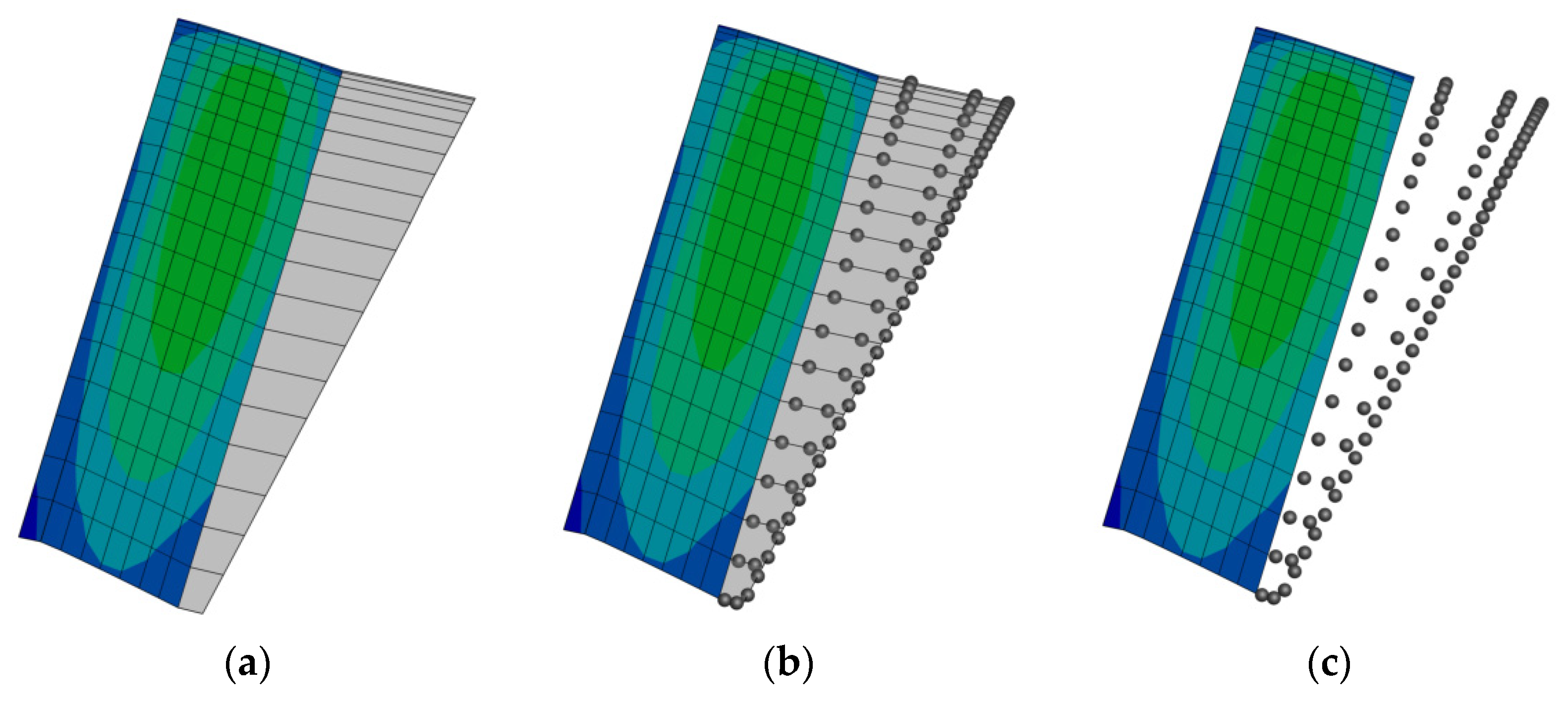
The process of converting vortex particles from vortex ring panels is depicted in Figure 1. In each time step, the blade’s panels’ positions are updated according to the translational and rotational velocities, while a new row of inviscid vortex wake panels is shed from the trailing edge of the blades according to the displacement. Then, the trailing and shed vortex straight-line elements of the inviscid wake panels are converted into their equivalent viscous vortex particles whose strength is proportional to the circulation difference between adjacent panels. Note that the upstream vortex lines of the vortex ring are kept unchanged to prevent the jump in circulation at the trailing edge. The strength of the new vortex particles converted from a single vortex straight-line element are computed as follows:
where is the vector length of the straight-line vortex element, is the circulation difference between two adjacent panels and n is the number of vortex particles to approximate the straight-line vortex element.
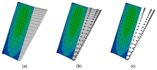
Figure 1.
The process to convert vortex rings to vortex particles, (a) creation of shed wake panels, (b) conversion of the trailing and shed straight-line elements of wake panels to vortex particles, and (c) suppression of the trailing and shed straight-line elements of wake panels.
2.4.2. Induced Flow Variable Computations
The pairwise interaction of particle–panel, particle–particle, panel–particle and panel–panel all contribute towards the induced velocity and the induced velocity gradient to viscous particles update. The methods to compute the induced velocity and the gradient for different types of interactions between the particles and vortex straight-line elements are summarized in Table 2.

Table 2.
Summary of induced velocity and induced velocity gradient calculations.
The gradient of velocity induced by a vortex straight-line element at a viscous particle can be computed by firstly reformulating the Vatistas smoothing kernel in Equation (4) as in Equation (19):
where scalar , and vector are given as follows:
The spatial derivative of Equation (19) can be obtained as follows:
where:
2.5. Fast Multipole Method (FMM)
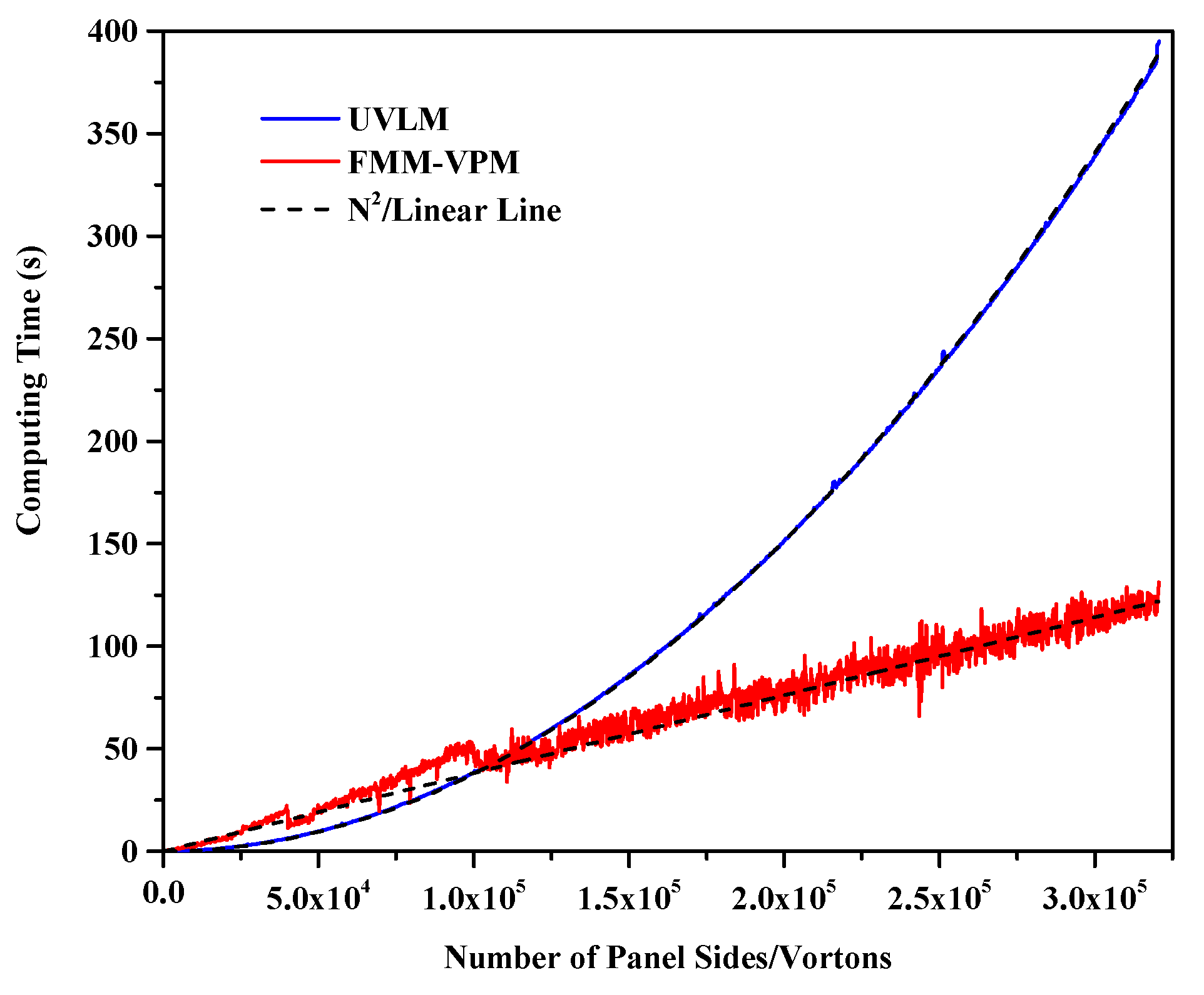
The fast multipole method (FMM) [68] is adopted to reduce the complexity of the standard pairwise interaction from to , thus accelerating the computations of the induced velocity and induced velocity gradient of the vortex particles with the price of a controllable error that comes from the replacement of the contribution of distant particles by multipole expansion of the group of particles. Figure 2 shows, for an increasing number of wake elements, the computation time for one step of the induced velocity computation using the direct method for the UVLM with wake panels compared with the induced velocity and velocity gradient for the VPM with FMM. Linear and quadratic reference curves having the same computational time at 200,000 elements as the VPM-FMM and UVLM, respectively, are also shown. The reference number of elements is taken large enough to ensure that the highest power of N is the dominant factor in the recorded computational time. The changes in the FMM time happening at 40,000 and 100,000 particles are caused by a predetermined switch in the number of FMM levels. The FMM level is the number of times the boxes are recursively subdivided and is chosen to ensure an optimal number of particles in each multipole expansion. For LES computations, the gradient of the filtered velocity is precomputed using FMM for each particle. PSE is then employed at the leaf level of the octree grid using particle to particle interactions.
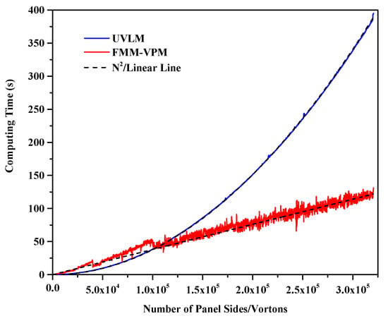
Figure 2.
Time for wake evolution steps versus the number of elements for direct UVLM and FMM VPM.
2.6. Ground Modeling
The ground is simulated using the well-known mirror image method, where the no penetration condition is automatically satisfied when a symmetry of the simulation is carried about the desired ground plane (lifting surface and wake reflections are performed). The fast-multipole method is adapted to consider the mirror wall boundary condition by creating the reflected particles and using the FMM as usual.
2.7. Non-Linear Unsteady Vortex Lattice Method (NL UVLM)
UVLM is a 3D potential flow method. Hence, the aerodynamic force captures no viscous nor compressible effects, while capturing the induced drag component. The flow remains attached all the way to the trailing edge without separation, thus having a linear lift slope. Potential methods can model separation by shedding singularities at every known separation point. This can be useful when a separation point can clearly be predicted such as the leading edge of a delta wing [69] to simulate the non-linear lift increase. In the NL VLM, viscous effects such as separation are entirely contained within the higher fidelity database and the role of the 3D VLM is simply to find the local effective angle of attack. It has been shown by [18,20] that the slat/main/flap wakes of aircraft wings and even wing stall [22] can be modeled with a simple flat plate with trailing edge wake panels using NL VLM. This work assumes that the ability to capture separation on the blades carries to NL UVLM for rotary wing aerodynamics.
Non-linear coupling adds the possibility to simulate arbitrary sectional lift functions instead of the UVLM linear incompressible thin airfoil and include other coefficients at converged sectional lift. In this work, 2D viscous profile data enables the inclusion of profile pressure and friction drag components that are not captured by UVLM alone. The method is general enough to handle the incorporation of any effect which can be reduced to a sectional lift and drag database ( and ), given that a 2D database of the effects can be constructed. The computational cost of the viscous coupling is thus mostly encapsulated by the construction of the databases, which needs to be completed only once per profile and condition combination. The runtime cost of this algorithm is negligible compared with the most time-consuming parts of the UVLM algorithm.
The viscous coupling in NL UVLM takes advantage of higher fidelity 2D aerodynamic computations at different spanwise sections to correct the inviscid 3D method. The Γ and the α methods are two well-known algorithms that can achieve this task. The Γ method [22] is less robust since it strongly relies on the under-relaxation to achieve convergence and the method fails in the post-stall region. There has been some development of a non-linear vortex lattice method for rotor blades based only on the Γ method [49], later extended to propellers [70] and wind turbines [71]. Additionally, these methods use an arbitrary point at which the induced velocities are computed instead of using the fact that a blade section is a 2D incompressible thin profile with a lift coefficient slope . The α method proposed by Van Dam [17] is generally preferred as it is unambiguous even in post-stall situations and requires significantly less relaxation to achieve convergence in the non-linear region.
The viscous coupling considered in this work is the Van Dam α method [17] as modified by Gallay [19,22,72] to remove the dependency of the viscous slope in the coupling algorithm. In this modified α, the collocation points are adapted to reflect a slope of in the UVLM. Firstly, the effective angle of attack is obtained using sectional lift coefficient computed with the Kutta–Joukowski theorem in Equation (29) and the known sectional lift curve slope. The sectional lift coefficient is then interpolated at the effective angle of attack in the viscous database. Section lift is used to update the UVLM sections angle of attack. The circulation is recomputed at every iteration by solving the UVLM-VPM linear system of Equation (3). The viscous coupling algorithm is given as follows:
- Viscous Coupling Algorithm
- 1.
- Solve the hybrid UVLM-VPM to obtain circulation distribution.
- FOR every spanwise section DO
- 2.
- Compute using Kutta-Joukowski theorem Equation (29)
- 3.
- Calculate the effective angle of attack :where is the iterated variable initially set to the section free stream angle of attack .
- 4.
- Interpolate the viscous lift () at the effective angle of attack from a database.
- 5.
- Update with relaxation factor ε the local angle of attack in the right hand side of the UVLM:END DO
- 6.
- Go to 1 until
Convergence of the viscous coupling algorithm occurs as the lift at each spanwise section in the UVLM-VPM is identical to that of the local 2D viscous database associated to that section, while still enforcing a modified UVLM boundary condition. This modification is simply a change in the free stream angle of attack. This coupling procedure is excessively efficient because it requires no geometry handling, even for important profile geometry deviation from the UVLM incompressible thin airfoil, as the effects are included numerically by the coupling procedure via the viscous database. When convergence is obtained, the effective angle of attack is known at every station, enabling the interpolation of any other profile coefficient such as 2D drag, moment or heat transfer coefficient.
2.8. Force Calculations
The steady and unsteady aerodynamic forces can be computed on each panel side using the Kutta-Joukowski theorem and at the panel center using the unsteady Bernoulli formulation, respectively:
where is the freestream density, is the rate of change of the panel circulation with respect to time and is the surface area of the panel. Each panel total force is summed to compute three overall coefficients for rotary wing aerodynamics: the coefficient of thrust , the coefficient of torque and the figure of merit , defined as follows:
where is the rotor radius, is the rotational velocity of the blades and is the total force along the thrust axis ;
where is the summation of the torque caused by each force at a distance away from the center of rotation, projected on the thrust axis:
with a hovering efficiency computed by the ratio of the ideal minimum torque needed to generate this thrust as given by momentum theory over the actual torque of the rotor.
It is also useful to define the 2D (per unit span) sectional lift and drag coefficients as follows:
where and are, respectively, the lift and drag forces generated by the 2D section, is the nondimensionalized speed and is the surface of reference. In this work, the nondimensionalized speed is taken as the speed induced by the rigid body rotation at the section. The 2D reference area is the total area of the panels in the 3D section. Note that the lower-case index is used for a 2D coefficient compared with the upper-case index for the 3D coefficients.
3. Test Case
The test case treated in this work is the four bladed S76 1/4.71 scaled rotor model geometry with rectangular tip as presented in the AIAA 2nd Hover Prediction Workshop [73], both out and in ground effects. The blades geometry as described by Balch and Lombardi [74] extends from 269.0256 mm at the root to R = 1423.416 mm at the tip. The profiles used are SC1013-R8 at root position 0.189 R, SC-1095-R8 from 0.4 R to 0.8 R and SC-1095 from 0.84 R to 1.0 R, with linear transitions between the airfoil changes. The chord is 79.4918 mm from the root to 0.8 R and 78.74 mm from 0.84 R to tip, also with a linear transition between the chord change. The blades have a −10° linear twist for most of the span, except for a small positive linear twist region near the root. The collective angle is taken at 75% of the span. The rotor solidity is 0.07043. The tip Reynolds number is taken to be and for the tip Mach number of 0.6 and 0.65, respectively. Only the rectangular tip shape is tested as the scope of this paper is to show the usability of a new method. Validations using other tip geometries (swept, tapered and anhedral tip geometries also exist) are deemed to be part of further work even though the viscous coupling algorithm with viscous sectional data computed with infinite swept wing assumption has been studied by the authors’ research group [20] for aircraft wings.
4. Rotor-Blade Modeling
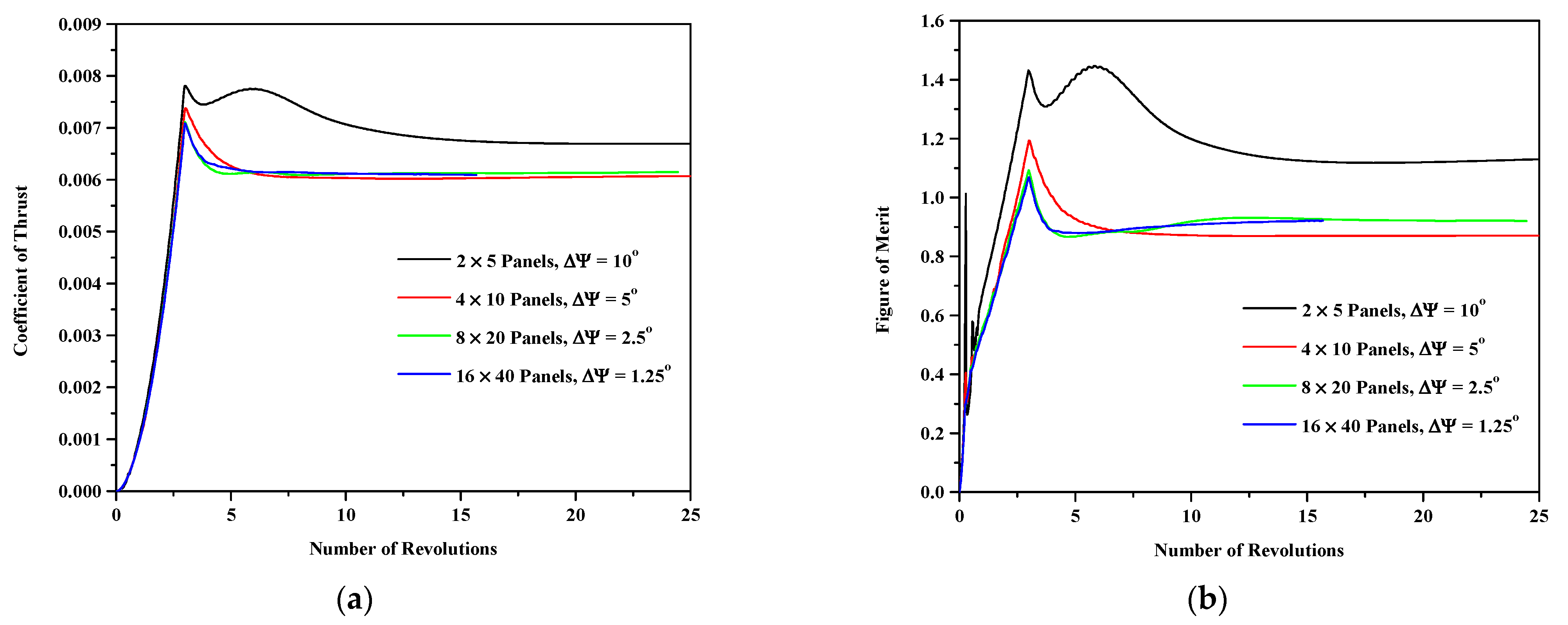
A lifting surface paneling and temporal refinement study is first performed. Figure 3 shows the convergence of the coefficient thrust and the figure of merit for four different mesh and time discretizations when simulating the out of ground effect at a collective angle of 9.25° and a tip Mach number of 0.65. The coarsest mesh discretizes each of the four blades using two chordwise panels and five spanwise panels, and the time step allows the blade to advance by an azimuthal increment ∆Ψ = 10°. Each level of refinement doubles the numbers of chordwise and spanwise panels and divides the time step by two. All the simulations were run for at least 24 rotations to ensure convergence, except for the finest discretization (16 × 40 panels, ∆Ψ = 1.25°) that could only reach about 15.7 rotations in 42 days on 1 node of 40 cores. The convergence of the coefficient of thrust shows that most of the simulations behave similarly reaching a maximum thrust coefficient at the end of the three slow started revolutions and smoothly converging to a stable coefficient of thrust. Only the coarsest discretization is qualitatively different, reaching a second peak after the first one. The finest and the second finest discretization (16 × 40 panels, ∆Ψ = 1.25° and 8 × 20 panels, ∆Ψ = 5°) converge to a very similar coefficient of thrust that is slightly larger than the second coarsest discretization (4 × 10 panels, ∆Ψ = 5°). The figure of merit convergence shows a little bit more variation where the coarsest discretization still has a second peak, the second coarsest discretization smoothly descends to a converged figure of merit and the two finest discretizations are slowly increasing towards convergence after the initial peak. Overall, the figure of merit convergence shows that the two finest discretizations are closely following each other, although the finest simulation could not be converged as far as the other discretizations because of the computational cost incurred.
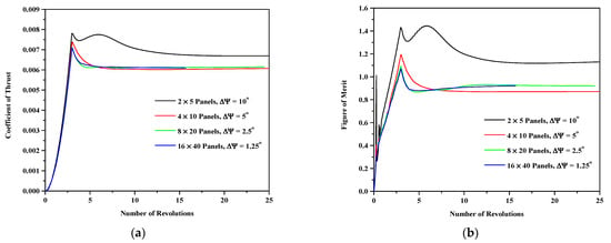
Figure 3.
Convergence of (a) the coefficient of thrust and (b) the figure of merit for four different lifting surface and time discretizations at a collective angle of 9.25° and a tip Mach number 0.65 out of ground effect.
Table 3 shows the difference in percentage for the different converged coefficients and their peak value obtained at the end of the slow started rotations. The chosen reference for the difference is the second finest discretization as it is the finest that has obtained full convergence on all coefficients. It can be seen that the error consistently diminishes as the discretization is refined for all of the six columns. Comparison of the reference with the two coarsest discretizations shows an unexpected trend, as the variation in converged coefficients of thrust and torque are of an opposite sign, yielding a large difference for the figure of merit. On the contrary, comparison with the finest discretization is consistent where an increase in thrust also produces more power. The converged and peak coefficient of thrust between the two finest discretizations agree well (less than 1% difference). The converged and maximum coefficients of power show slightly more difference at about 1.5%, but this might be expected at different thrust values. The converged figure of merit is incredibly close (less than 0.1%), but caution is required since the finest discretization might not be fully converged. The largest difference between the two finest discretizations is found for the peak figure of merit with slightly more than 2%. Since the aim of this article is to provide converged hover results, the peak values are additional information of lesser importance than the converged results. The second finest discretization is therefore chosen for the remainder of this work as it shows similar converged results as the finest while obtaining convergence much faster. The four blades are each modeled using 8 × 20 vortex panels mesh on the camber line for the linear case and on a straight line from leading edge to trailing edge when viscous coupling is used, as the coupling adequately models the aerodynamic effects of camber, compressibility and viscosity at the different sections [19].

Table 3.
Difference in percentage for the converged and peak coefficient of thrust, coefficient of power and figure of merit using the Mesh 8 × 20, ∆Ψ = 2.5° as the reference for the different discretizations.
For the use of NL UVLM, an additional viscous discretization is needed. For a constant profile blade, as the Reynolds number varies linearly along the span, the viscous databases should minimally be provided for the root and tip conditions to enable spanwise linear interpolation [24]. Viscous data should also be provided at any cross section change. Thus, the databases are generated at root and tip and at every profile switch along the blades which occurs at r/R = 0.4, 0.8 and 0.84. This leads to five stations for given tip Mach and Reynolds numbers. The interpolations are accomplished via Akima splines within the database and by linear interpolation between sections. Two different sets of databases are tested.
First, an empirical correlation (later referred to as correlation) given by Bousman [75] is used. Equations (1) and (2) in the reference are used to generate the lift and drag database, where CLmax and the zero lift angle of attack can be recovered by averaging values in the reference Tables 7 and 8 and Figure 27, respectively. Though easy to generate, the reference is unfortunately lacking the details of the root profile and the coefficient of drag is assumed to remain constant (Cd0). As the SC1013-R8 is a similar profile to the SC1095-R8 (albeit thicker), the latter is used at the root station, knowing that the thickness mostly affects the stalling characteristics and the considered test cases are all stall-free along the blades. The constant coefficient of drag assumption is reasonable at reduced angle of attacks but is a limitation at higher angle of attacks.
The second set of viscous data is generated using an in-house finite volume 2D RANS solver which solves the 2D RANS equations on a multiblock structured grid using a second-order, cell centered finite-volume method with a matrix dissipation scheme and accelerated to a steady-state solution using the full approximation storage multigrid scheme [76]. The 258 × 128 mesh is generated keeping the y+ values close to 1.0. For the turbulence model, the Spalart–Allmaras one-equation model [77] is employed. This numerically generated database is therefore constructed by solving 2D RANS using the correct airfoil geometry and the corresponding Mach and Reynolds at each of the five stations along the S76 rotor blades. The effect of Coriolis, centrifugal forces and the existence of crossflow in the rotating frame are neglected in this study. Even though the Reynolds number range on the rotor model might suggest important laminar to turbulent transition effects on the blades, the fully turbulent SA model is chosen in this study to remain as close as possible to most of the higher fidelity results from the 2nd Hover Prediction Workshop [73] where only two of the eight codes attempted to take into account transition. In the hover workshop result compilation, the differences between codes with and without transition (such as U of Tol and AFDD) were small, especially for the rectangular tip shape. The methodology of the NL UVLM presented here does not assume turbulent flow, as this assumption is encapsulated in the database that can be generated with a laminar, turbulent or transitioning higher fidelity 2D code.
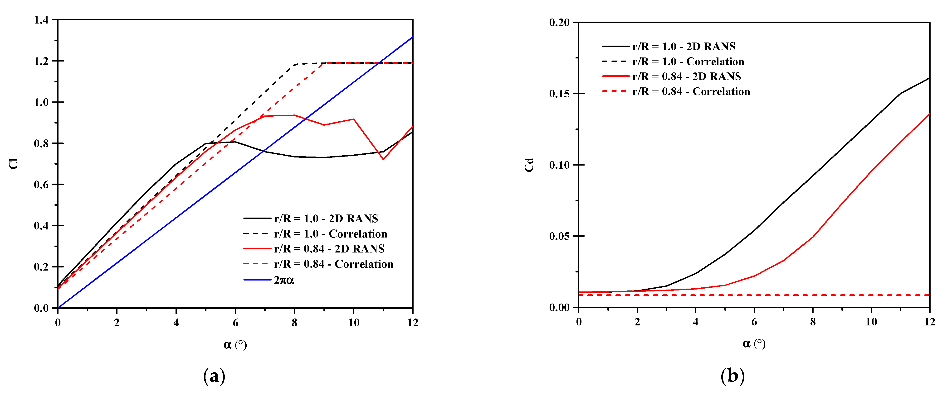
Figure 4 shows the lift and drag curves at the blades tip and 0.84 R. The lift curves are qualitatively similar for both databases, but the 2D RANS data fortuitously predicted more lift than the empirical correlation relationships in the linear region at all of the five blade stations. The importance of the differences between the databases in this work is to observe the results sensitivity of the NL UVLM algorithm with respect to its inputs. The 2D RANS data expectedly generates more drag than the empirical correlation data having a constant drag assumption. The black dashed line is hidden under the superimposed red dashed line in Figure 4b as both sections have the same Cd0.
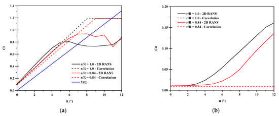
Figure 4.
Viscous database of SC-1095 from 2D RANS and data correlation. (a) Lift curves varying with effective angle of attack. (b) Drag curves varying with effective angle of attack.
5. Results
Comparisons are based on the 2nd Hover Prediction Workshop compilation as reported by Hariharan [73]. In that article, 3D URANS results are shown separately for the structured and unstructured solvers as well as hybrid 3D URANS near field and Lagrangian far field wake representations. Because UVLM-VPM and NL UVLM-VPM are also Lagrangian methods that conserve vorticity in the wake, they are expected to match the hybrid 3D RANS—Lagrangian wake best, especially with the NL UVLM-VPM where a higher fidelity 2D lift and drag are used.
5.1. Out of Ground Effect (OGE)
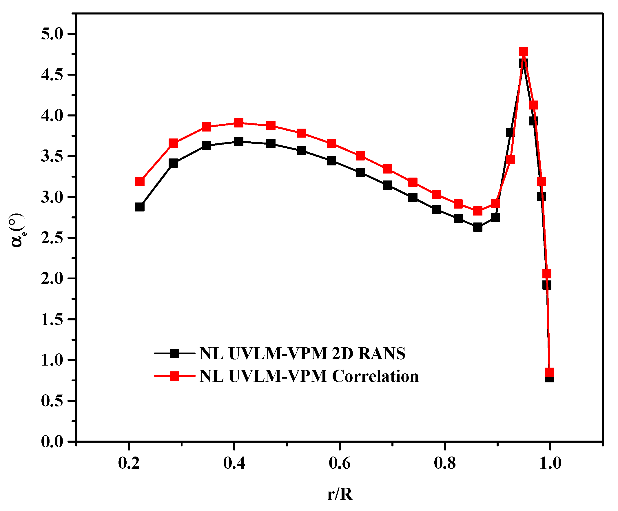
Simulations of the out of ground effect are performed at a tip Mach number of 0.65. Figure 5 shows the effective angle of attack distribution along the span of the blades at a collective angle of 9.25°, the highest collective simulated with the NL UVLM-VPM. Interpolation in the databases at the given effective angle of attacks allows to conclude that all the cases simulated with NL UVLM-VPM are free of stall along the blade and only the peak loading region experiences significant non-linearity from the RANS database at high collective angles. Therefore, neglecting the 3D stall delay is not expected to cause significant differences for the blade loading near the root.
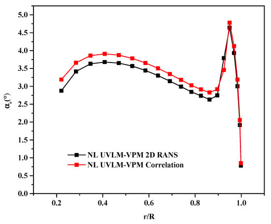
Figure 5.
Effective angle of attack distribution along the span at a collective angle of 9.25° and tip Mach number of 0.65 out of ground effect using the RANS database in black and Bousman experimental correlation in red.
5.1.1. Global Coefficients
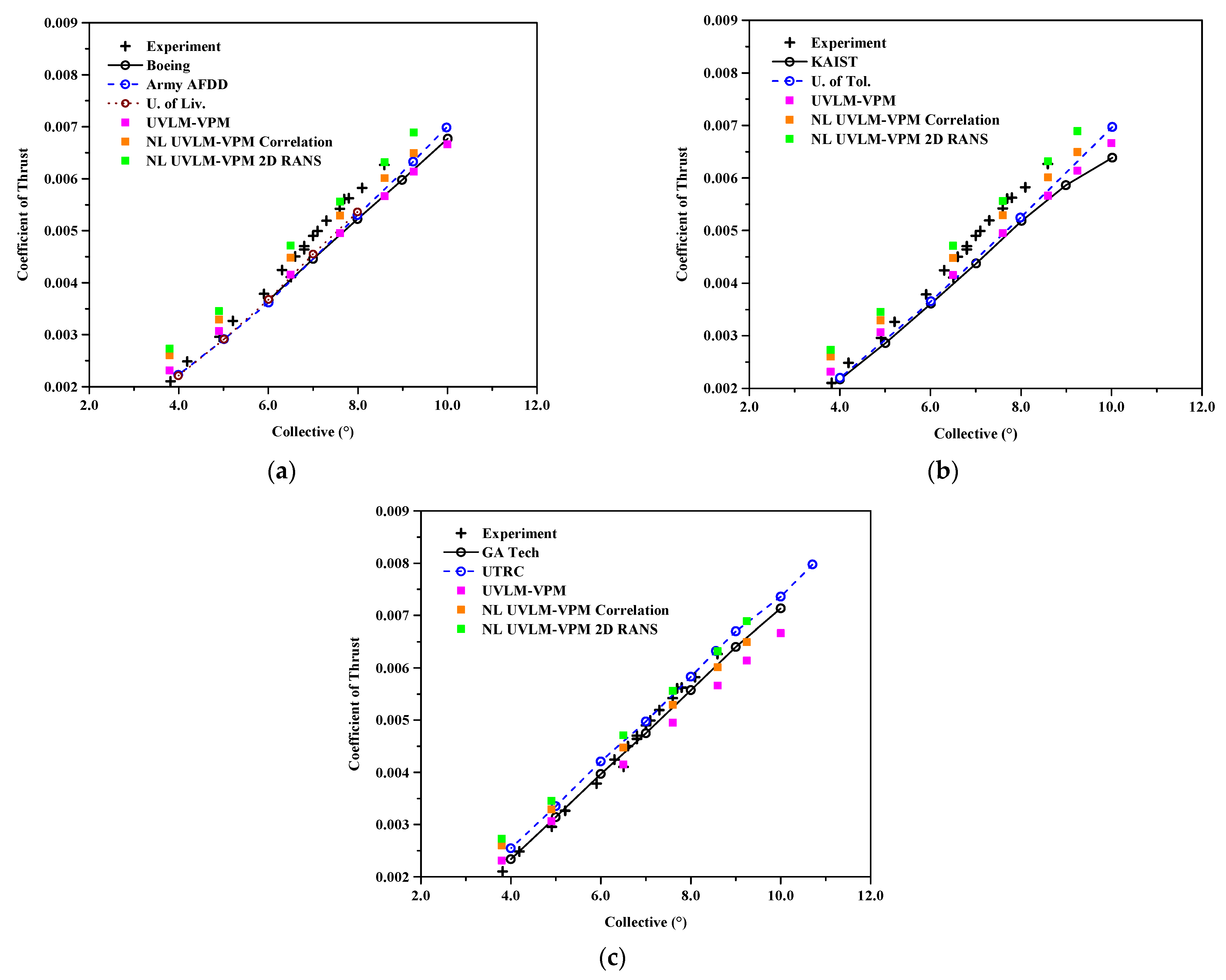
Figure 6 shows the coefficient of thrust with the collective angle for the hovering case far from the ground. The linear UVLM-VPM tends to under predict the aerodynamic forces as it does not model the compressibility effects. It is worth noting that the linear UVLM-VPM follows fairly well the structured codes results for the thrust prediction except for the two lowest collective angles. The addition of the viscous coupling algorithm increases the coefficient of thrust compared with the linear case because of the addition of viscous and compressibility effects, therefore having a lift slope higher than the incompressible thin airfoil theory in the linear region, as expected. Introducing locally the viscous and compressibility effects, the NL UVLM-VPM results tend towards the 3D URANS-Lagrangian wake methods, except at lower collectives where the linear UVLM-VPM already well predicts the thrust coefficient compared with the 3D RANS-Lagrangian method. Therefore, adding the non-linear coupling at lower collectives causes an overprediction of the thrust coefficient. As the collective angle is increased, the 2D RANS database predicts the experimental CT the most accurately compared with the correlation database and the linear case. The growing difference between the viscous coupling using 2D RANS and correlation is explained by the database used where the 2D RANS consistently predicted a higher 2D Cl than the correlation at the given effective angle of attacks as shown in Figure 4 (note that all sections in all cases remain at lower effective angles of attack than stall values). The coupling algorithm results are therefore consistent with the databases used as increasing sectional 2D lift increases the overall CT. Nevertheless, the 2D RANS database is much easier to generate at the exact desired conditions of the Mach and Reynolds numbers via a 2D RANS solver while the correlation database requires experiments on the given geometry in similar conditions which are usually much more expensive to obtain.
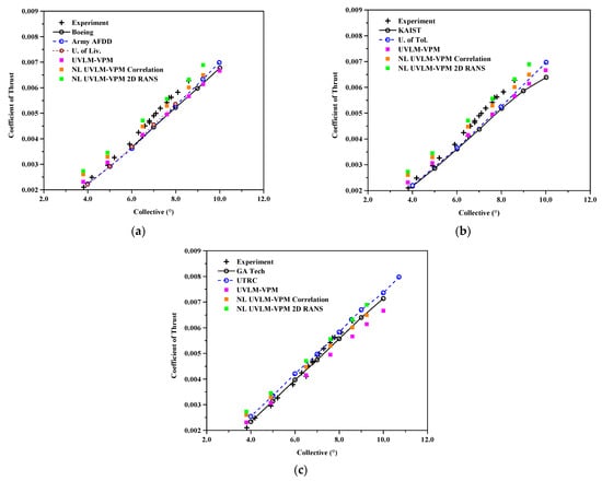
Figure 6.
Coefficient of thrust varying with collective angle, comparisons between Hybrid UVLM-VPM and experimental data with (a) 3D RANS structured codes, (b) 3D RANS/DES unstructured codes, and (c) hybrid 3D RANS-Lagrangian codes.
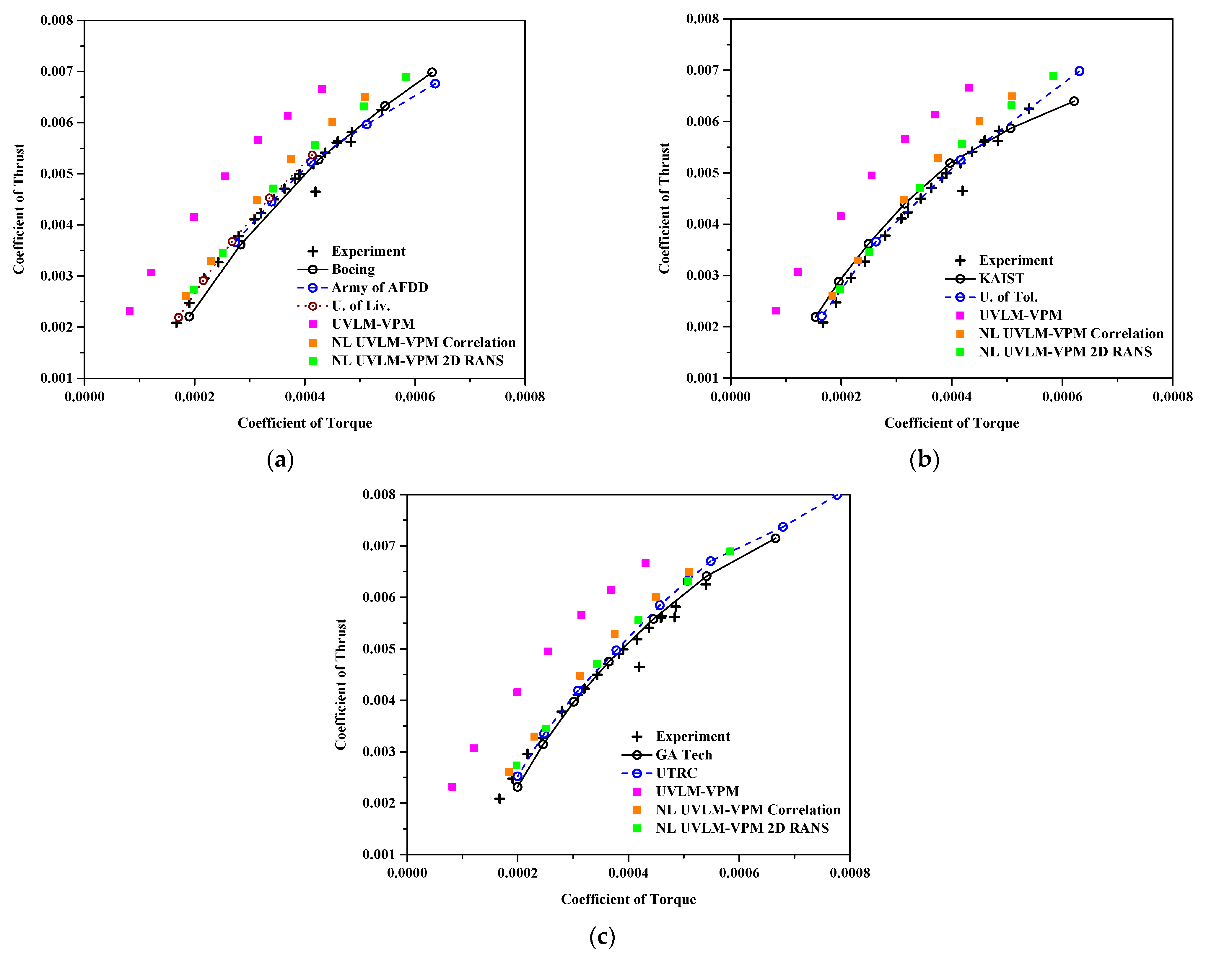
Figure 7 shows the coefficient of thrust varying with the coefficient of torque. The UVLM-VPM shows a significant difference with the NL UVLM-VPM because it captures only the induced component of the drag, whereas the viscous coupling adds local viscous and pressure drag components. Note that the 2D database can include wave drag in a transonic regime. Therefore, the torque is much more accurately predicted with the NL UVLM-VPM as a more realistic drag is computed along the blades. Since the drag is interpolated at the computed local angle of attack from the viscous coupling algorithm, the results using correlation and RANS predict a similar torque at low CT (because they have a similar Cd0); however, the RANS data predicts more drag as the local angle of attack is increased, meaning more torque as a collective is increased. On these plots, the RANS database is the closest to the other numerical methods and experiment while still predicting too low torque values at the highest collectives. The results compare well with 3D URANS-Lagrangian methods.
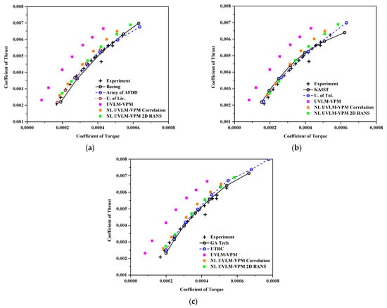
Figure 7.
Coefficient of thrust varying with coefficient of torque , comparisons between hybrid UVLM-VPM and experimental data with (a) 3D RANS structured codes, (b) 3D RANS/DES unstructured codes, and (c) hybrid 3D RANS-Lagrangian codes.
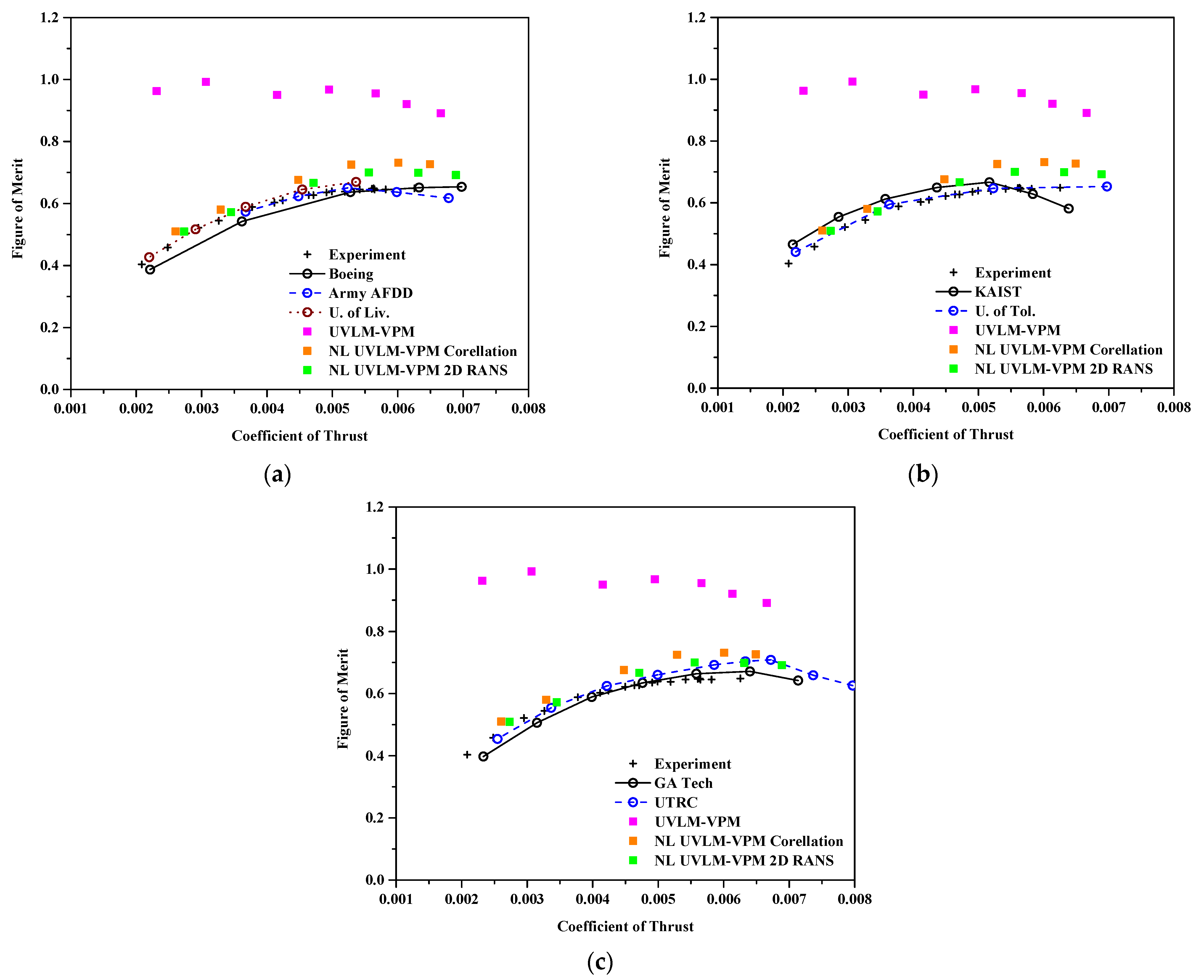
Figure 8 shows a similar trend with the figure of merit, which is a measure of the efficiency of the rotor. Overall, the linear UVLM-VPM predicts too low torque, which causes its figure of merit to be close to unity. In contrast, when adding the viscous coupling, the figure of merit measures much closer to the experiment and higher fidelity values. Hence, the figure of merit for the NL UVLM-VPM using RANS database agrees well with the 3D URANS-Lagrangian methods. At the highest thrust coefficient, the low torque predicted by the NL UVLM-VPM directly translates into an overestimated figure of merit.
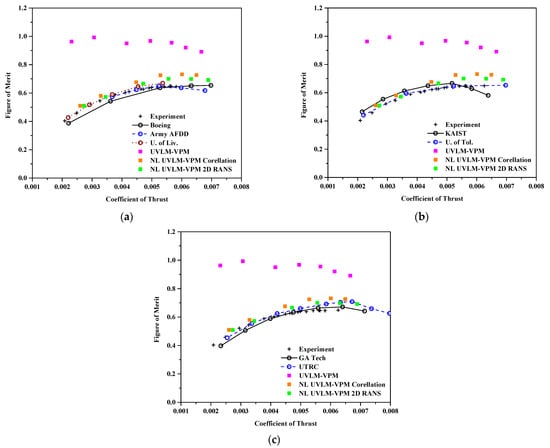
Figure 8.
Figure of merit with coefficient of thrust , comparisons between hybrid UVLM-VPM and experimental data with (a) 3D RANS structured codes, (b) 3D RANS/DES unstructured codes, and (c) hybrid 3D RANS-Lagrangian codes.
5.1.2. Error Compared with Experimental Results
From the qualitative figures presented in the previous section, the quantitative error of each method is compared with the experimental results. To reduce the amount of data, only the coefficient of thrust and the figure of merit are compared. Data cannot be directly compared, firstly because all methods have not been tested at the same collective and thrust as the experimental data and secondly because a direct comparison would not consider possible outliers in the experimental data. To perform the comparison, the trend lines are first obtained from the experimental data. A linear trend line is chosen for the coefficient of thrust as a function of the collective angle and a quadratic trend for the figure of merit as a function of the coefficient of thrust. Then, the trend lines functions are used to predict the experimental values at the collective angles of attack of the methods. The relative error is simply the difference of the predicted value of the method and of the experimental value divided by the predicted experimental value. Since the experimental data is only available up to a collective of about 8.6°, the values above that are ignored for the figure of merit comparison, since extrapolation is risky if the trend is not maintained outside the data points. In fact, some methods predict a plateau after that value, while others continue decreasing. From the available data, it is not possible to determine which is correct. Note that the values above 8.6° are kept for the thrust comparison, since most methods do not show deviation from the linear trend for the thrust prediction.
Table 4 presents the mean and median relative errors of all methods compared with experimental trends. For the CT error, the UVLM-VPM and the two NL UVLM-VPM have among the largest errors for the mean error, but interestingly, the two NL UVLP-VPM have among the lowest median errors. That is because the two NL UVLM-VPM mean CT are “polluted” by the two lowest collective CT that are very far from the experimental values, but the rest of their predictions are much closer to the experimental data. In fact, if those two points are removed, the mean CT errors of the NL UVLM-VPM become 2.2% and 3.7%, respectively, for the 2D RANS and correlation, which would be the lowest mean CT errors. The other methods have a much closer mean and median CT error, meaning that their error is more evenly distributed across all their data points. For the FM error, as expected, the UVLM-VPM has the largest mean and median FM error compared to the experimental results and the 2D RANS has a smaller error than correlation for the NL UVLM-VPM since it models the increased drag at a higher angle of attack. The NL UVLM-VPM with the 2D RANS has a FM error among the highest of the high-fidelity methods, while still being better than the KAIST results.

Table 4.
Relative error compared with experimental trends.
5.1.3. Spanwise Coefficients
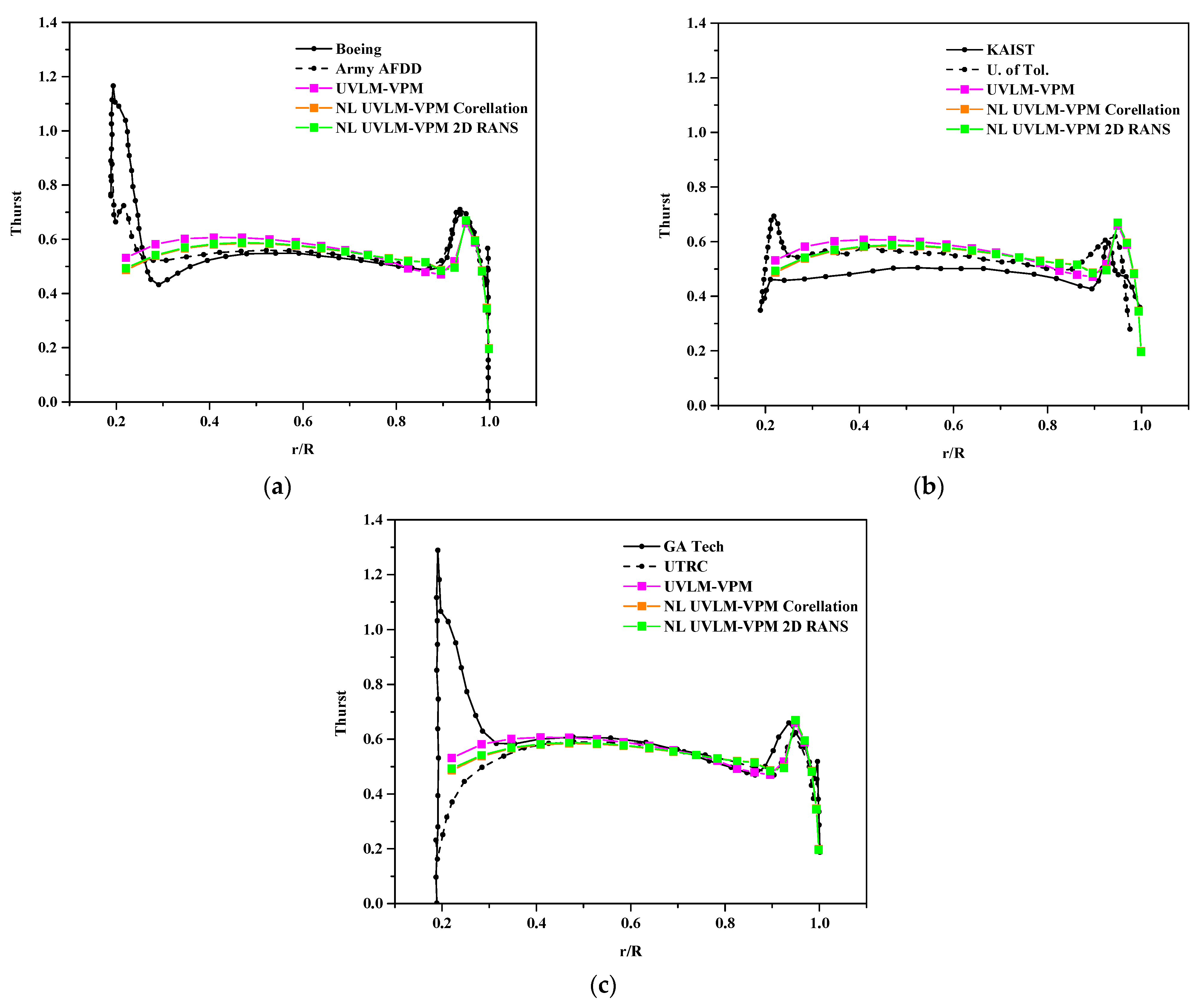
Figure 9 shows the distribution of the thrust nondimensionalized with the local rotational velocity along the blades at a given coefficient of thrust value of . To do so, the distribution of thrust from the two enclosing coefficient of thrust simulations are linearly interpolated at the given coefficient of thrust. Linear UVLM-VPM has a slightly different thrust distribution compared to both of the NL UVLM-VPMs which are almost indistinguishable. The main differences are the values at the root where the linear UVLM-VPM is higher than the NL UVLM-VPM and inversely in the region before the peak (), where the linear UVLM-VPM is lower than the NL UVLM-VPM. It is worth noting that both the linear and the non-linear methods agree well with most of the higher fidelity methods away from the blades’ ends but do not show the thrust increase near the root displayed by most 3D URANS results. This might be caused by the cosine tip refinement paneling that stretches the root panels as that region is of lesser interest for rotary wing aerodynamics. They both capture well the magnitude and position of the maximum loading near the tip, although the peak bumps are too narrow, while the higher fidelity codes have a smoother varying loading at that point. The thrust distributions are especially close to those predicted by 3D URANS-Lagrangian methods. The linear UVLM-VPM tends more toward the GA Tech thrust distribution while the two NL UVLM-VPM are closer to the UTRC distribution.
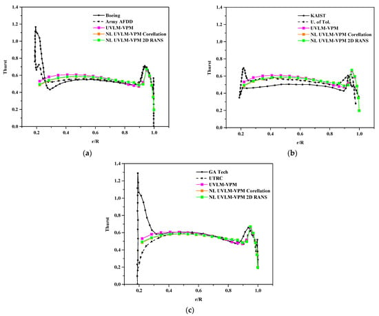
Figure 9.
Blade section thrust coefficient for comparisons between hybrid UVLM-VPM with (a) 3D RANS structured codes, (b) 3D RANS/DES unstructured codes, and (c) hybrid 3D RANS-Lagrangian codes.
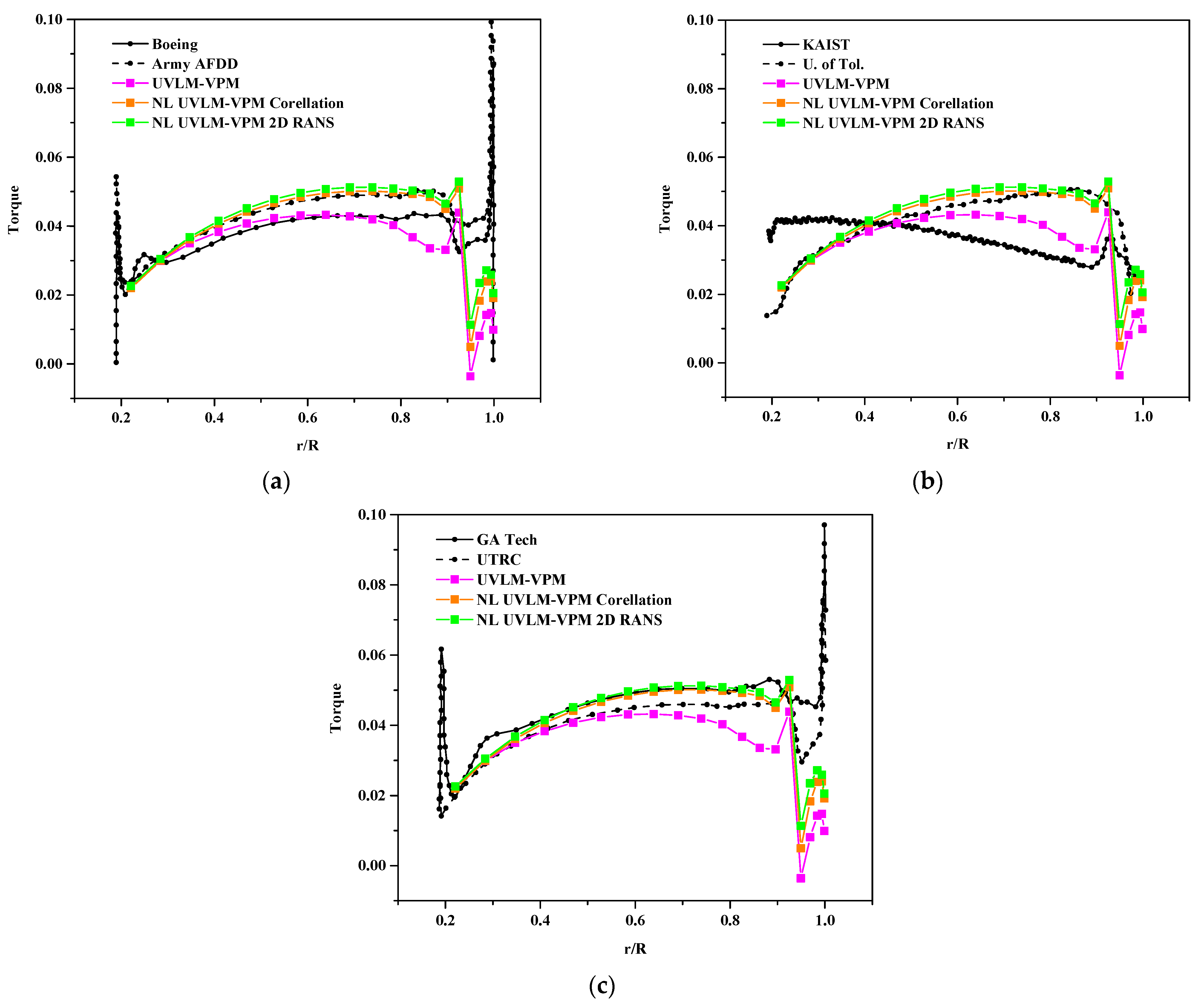
Similarly, Figure 10 shows the distribution of torque along the blades at the given coefficient of thrust. The linear UVLM-VPM undoubtfully shows low torque along the blades as it only considers the induced drag component. Comparing the NL UVLM-VPM with the correlation and 2D RANS databases at a similar thrust loading highlights the drag component difference in the databases (correlation only models Cd0 which causes a slight underprediction of the torque distribution); however, both databases’ results are close to the 3D URANS-Lagrangian method. The linear and non-linear UVLM-VPM do not have the high values near the ends of the blades as most of the other methods have. It has a much deeper dip in the torque distribution located at the maximum local thrust location near the blades tip compared to the other methods.
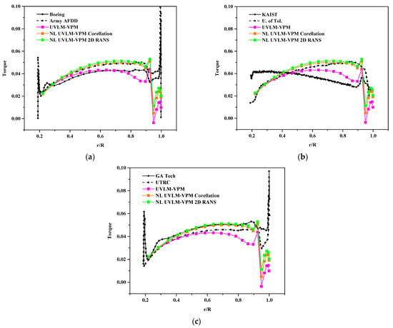
Figure 10.
Blade section torque coefficient for , comparisons between hybrid UVLM-VPM with (a) 3D RANS structured codes, (b) 3D RANS/DES unstructured codes, and (c) hybrid 3D RANS-Lagrangian codes.
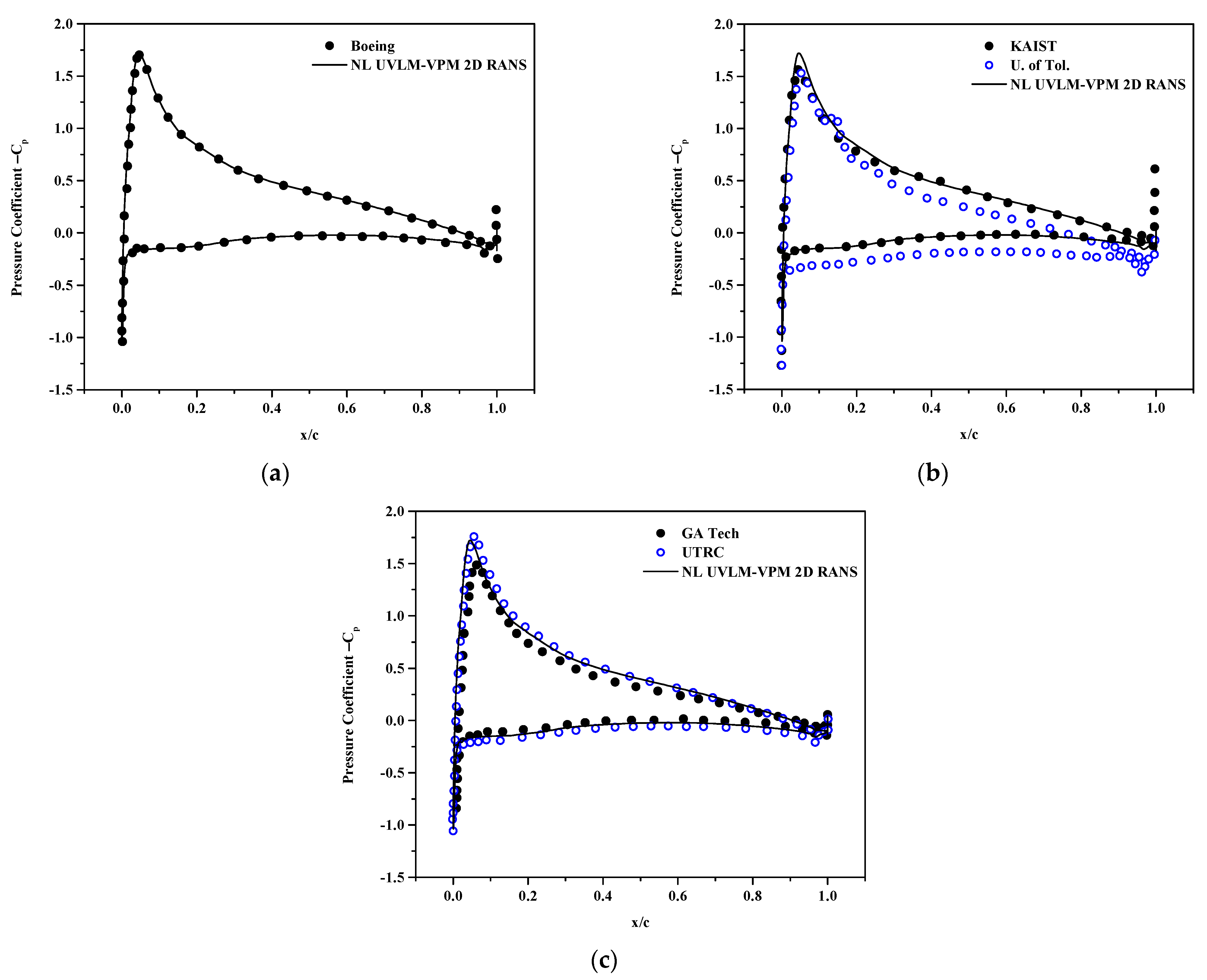
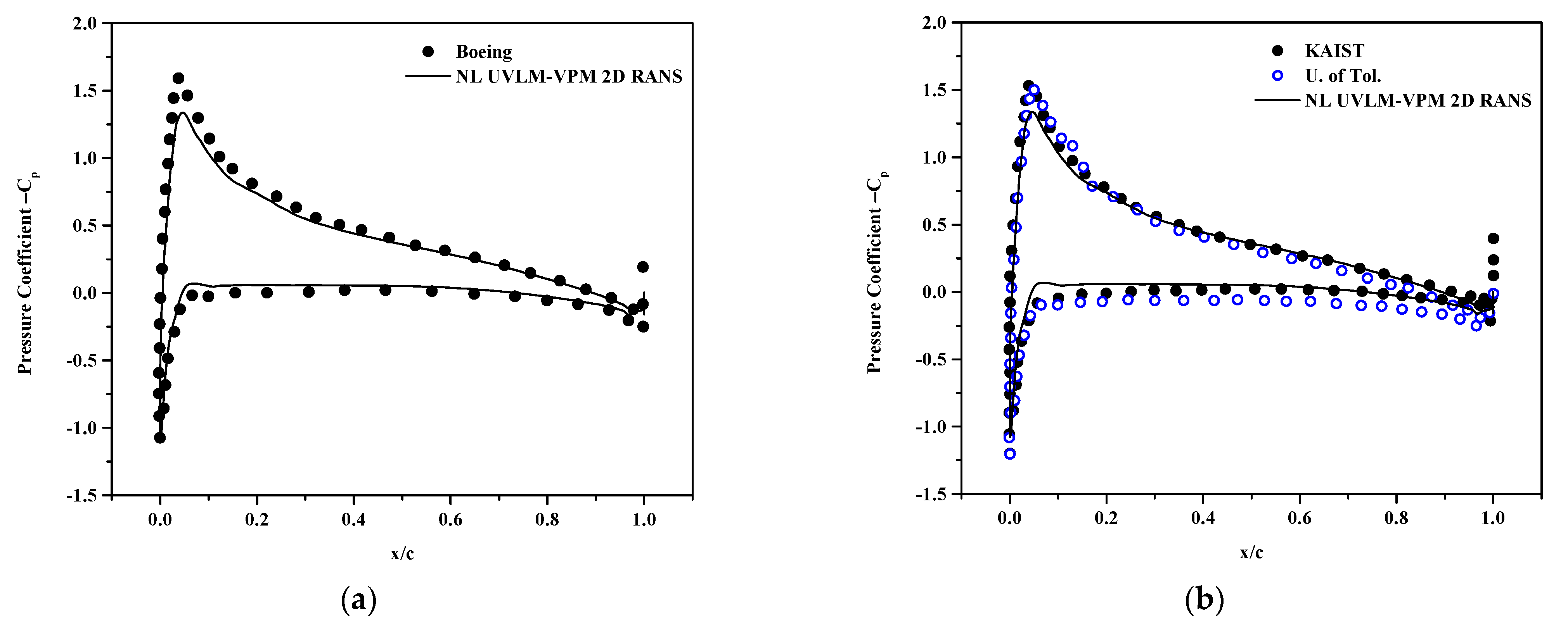
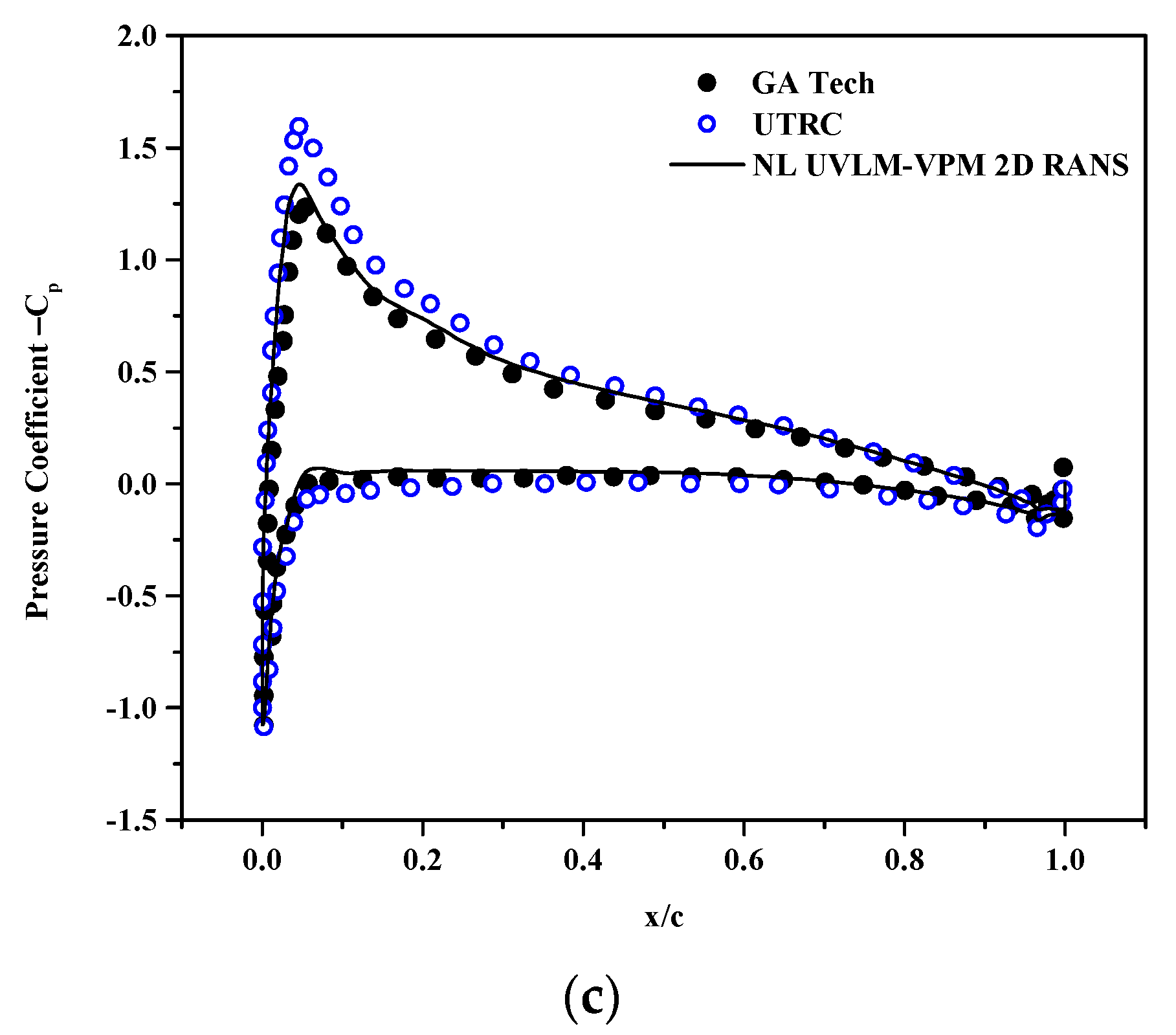
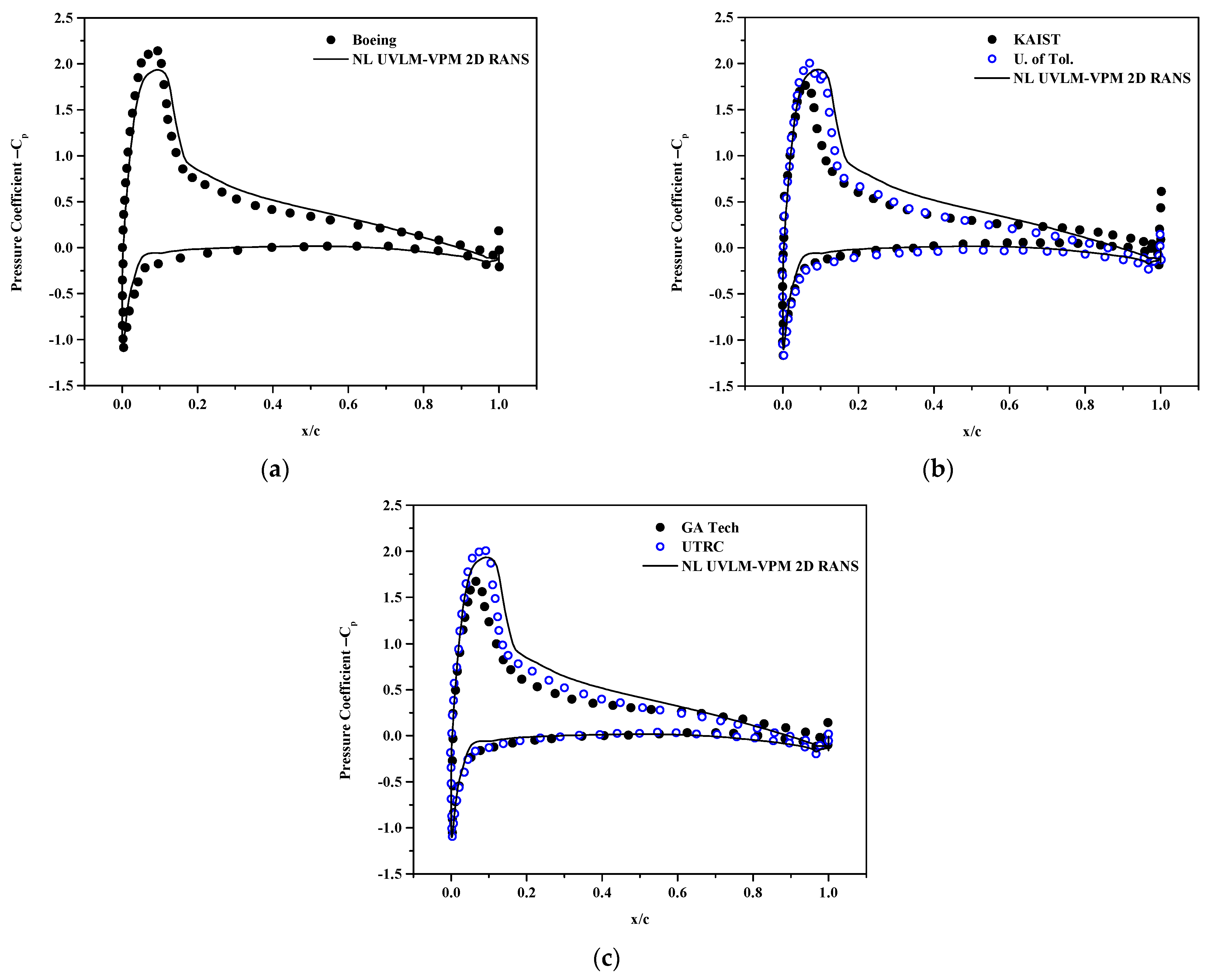
The coefficient of pressure at sections r/R = 0.6, 0.85 and 0.975 are plotted in Figure 11, Figure 12 and Figure 13, respectively. The NL UVLM-VPM allows to recover the coefficient of pressure by interpolating the calculated coefficient of pressure from the 2D RANS at the section effective angle of attack. The coefficient of pressure could not be plotted for the correlation database as only the coefficients of lift and drag are known, and not the coefficient of pressure. The differences in the solutions increase as the section is taken closer to the blades tip. Overall, the NL UVLM-VPM results remain between the two 3D URANS-Lagrangian methods at the two first stations and have a similar shape as the UTRC at r/R = 0.975. The coefficient of pressure and local distribution of thrust are tightly related; thus, it is likely that the Boeing and GA Tech results for the coefficient of pressure at that section suffer from the bump in the distribution of thrust shown at Figure 9. The agreement with the Boeing coefficient of pressure is excellent at r/R = 0.6 and good at r/R = 0.85.
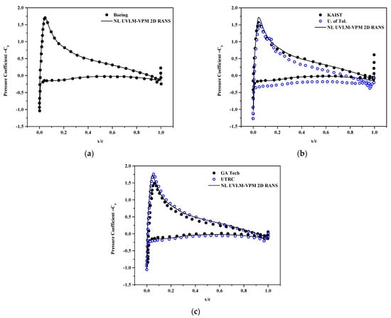
Figure 11.
Surface pressure coefficient at and , comparisons between hybrid UVLM-VPM with (a) 3D RANS structured codes, (b) 3D RANS/DES unstructured codes, and (c) hybrid 3D RANS-Lagrangian codes.
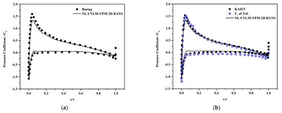
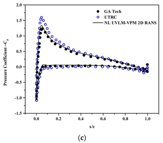
Figure 12.
Surface pressure coefficient at and , comparisons between hybrid UVLM-VPM with (a) 3D RANS structured codes, (b) 3D RANS/DES unstructured codes, and (c) hybrid 3D RANS-Lagrangian codes.
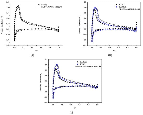
Figure 13.
Surface pressure coefficient at and , comparisons between hybrid UVLM-VPM with (a) 3D RANS structured codes, (b) 3D RANS/DES unstructured codes, and (c) hybrid 3D RANS-Lagrangian codes.
5.2. In Ground Effect (IGE)
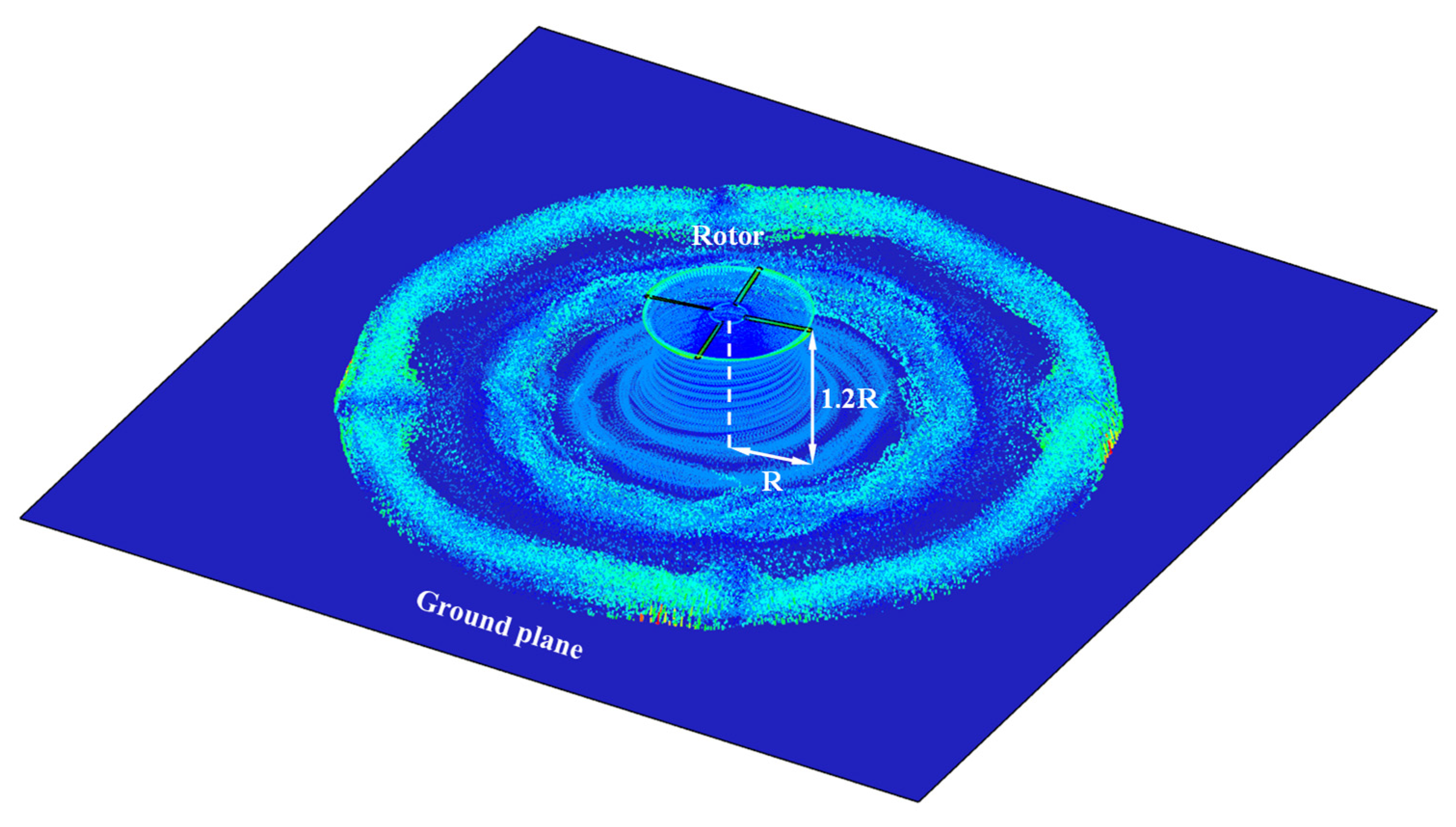
Figure 14 shows the simulations in ground effect performed at a collective angle of 9.25°, a tip Mach number of 0.6 and a nondimensional distance of z/R = 1.2 over the ground plane simulated with the mirror image method. The LES viscosity needed to stabilize the simulation in the wake is highest (red in the figure) in the starting vortex at the four azimuthal angles of the blades at the beginning of the simulation. The diffusion there ensures that the starting vortex remains under control as time moves forward. The LES viscous diffusion is small in the vicinity of the rotor, thus not diffusing excessively the important vortex features such as the blades’ tip vortex. The simulations are time stepped until periodic variation is found, and the results are averaged over the last few rotations.
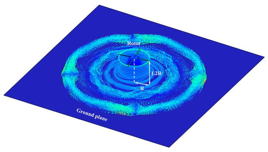
Figure 14.
Vectorial colored by the eddy viscosity of wake particles from the S76 rotor rotating with , collective pitch angle of 9.25°, and hovering at 1.2 R from the ground plane.
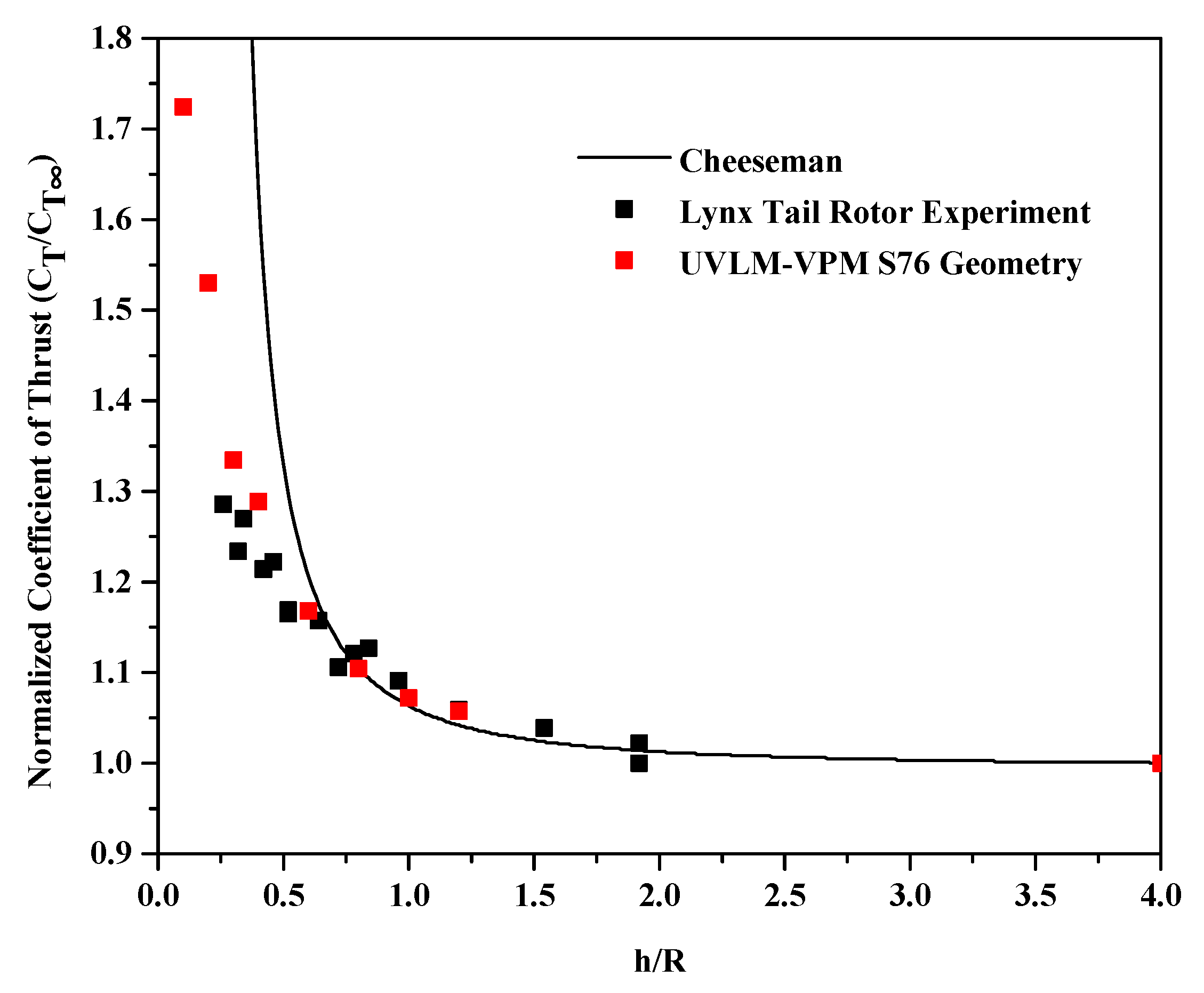
A test of robustness is first performed. Keeping the S76 geometry and the maximum collective simulated in this work (9.25°), the UVLM-VPM is tested at different ground heights. Figure 15 shows the increase of thrust in ground effect compared with the theoretical equation and experimental results on a different four-bladed rotor geometry. The Cheeseman theoretical equation [78] can be used to model the increase of thrust when a rotor is in ground effect normalized by the out of ground effect thrust. This equation is found by modeling the rotor and its image as sources and assuming a constant inflow velocity over the rotor disk. The Cheeseman equation follows the experimental data well in hover for a rotor height of 0.75 radius and above but overestimates the thrust increase as the rotor further approaches the ground up to its discontinuity at a 0.25 radius. Also shown on the plot is the experiment results of the Lynx Tail Rotor geometry in ground effect [79]. Even if the geometries are slightly different, the UVLM-VPM with the inviscid mirror image method captures better than Cheeseman theory the increase of thrust in ground effect measured in the experiment where the ground is inherently viscous.
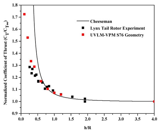
Figure 15.
Increase of thrust in ground effect comparing the Cheeseman theoretical equation, experiment results on the Lynx Tail Rotor geometry and the UVLM-VPM on the S76 geometry.
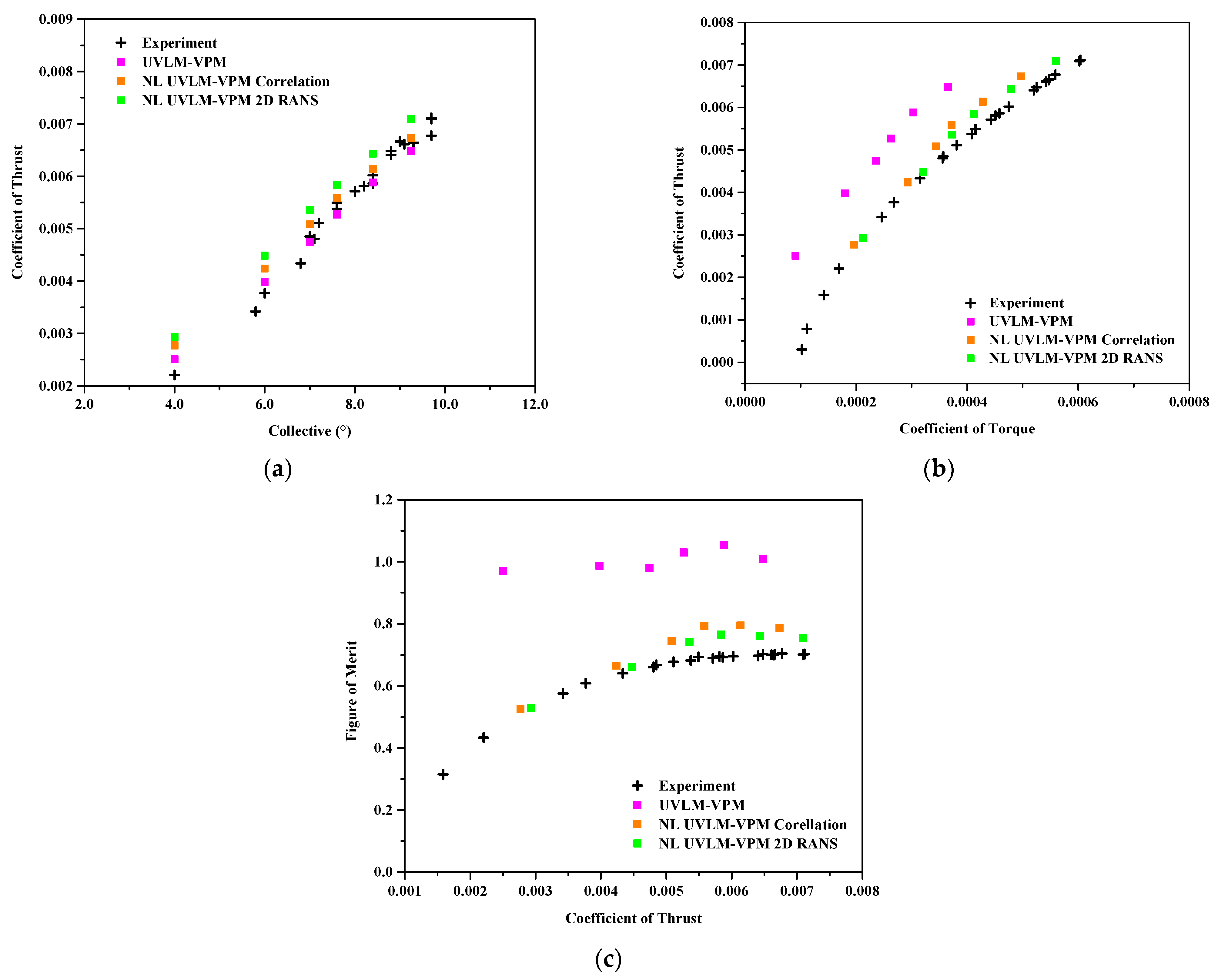
Results for the collective sweep at a height of 1.2 radius in ground effect generally show a similar behavior as the simulation’s out of ground effect, except that the linear UVLM-VPM does not under predict as much the coefficient of thrust in the higher collective region compared with the experimental data, as can be seen in Figure 16. Therefore, the addition of the viscous coupling offsets the predicted coefficient of thrust as it is expected, resulting in an over prediction of the coefficient of thrust, especially notable for the RANS database. The coefficient of torque and figure of merit show an identical trend as the case out of ground effect, where the NL UVLM-VPM with the RANS database is the closest to the experimental data and agrees better at lower thrust coefficients.
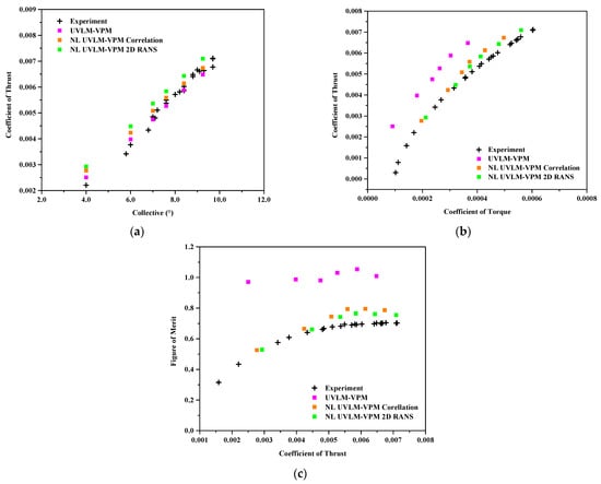
Figure 16.
Comparisons between hybrid UVLM-VPM with experimental data. (a) coefficient of thrust varying with collective angle, (b) coefficient of thrust varying with coefficient of torque , and (c) figure of merit varying with the coefficient of thrust .
6. Conclusions
In conclusion, this article details a new method towards rotor aerodynamics analysis that is the combination of the NL UVLM via the alpha coupling and the VPM with an added LES viscosity diffusion term. The added eddy viscous term is able to stabilize the simulations of a hovering rotor for both in and out of ground effects. A UVLM-VPM mesh independence test performed for the out of ground effect shows small differences in the results compared with those obtained with a finer mesh.
The non-linear UVLM-VPM greatly improves the torque prediction, which also improves the figure of merit, compared to the full potential UVLM-VPM, because the non-linear algorithm includes more physical drag components than the UVLM-VPM that only accounts for induced drag. For the case far from the ground, the results for the coefficient of thrust compare especially well in the region of interest with the experimental data and hybrid higher fidelity codes that conserve vorticity in the far wake. The sectional thrust and torque distributions as well as the coefficient of pressure enabled by the viscous coupling agree well with those given by the higher fidelity codes.
For the simulations of the in ground effect, only the comparison with experimental data is shown because the higher fidelity codes results are not available. The coefficient of thrust predicted by the linear UVLM-VPM is closer to the experimental data, so the addition of the viscous coupling does not improve significantly the coefficient of thrust prediction, but as for the out of ground effect case, the torque and figure of merit predictions are greatly improved by the non-linear coupling.
The new method could help simulate rotor aerodynamics where viscous effects are more important, such as smaller rotors, especially in a confined environment where UVLM alone can struggle. It also opens the door to new optimization the possibility of using this mixed fidelity tool with a relatively fast turnaround time. Note that discussions on the simulations’ time is deliberately excluded from this article as the focus is to demonstrate the usability of the results of the method and not to fully optimize the code. To give the reader an order of magnitude, the simulations of the in ground effect each take about three days on one supercomputer node with 40 cores parallelized with OpenMP in a C++ code, which is still much less in time and compute core resources than any reported 3D URANS rotor simulations.
Author Contributions
V.P.-C. and M.T.N. have equally contributed to the software development, results generation and manuscript redaction; S.P., G.M. and E.L. have contributed with conceptualization, substantial revisions of the manuscript and funding acquisition. All authors have read and agreed to the published version of the manuscript.
Funding
This work benefited from the financial support from the Natural Sciences and Engineering Research Council of Canada (NSERC) and CAE Inc. within a Collaborative R&D grant (no. CRDPJ 486001) as well as support from the Canada Research Chairs Program. Calculations were performed on Compute Canada/Calcul Québec clusters.
Conflicts of Interest
The authors declare no conflict of interest.
References
- Leishman, J.G. Rotorcraft Aeromechanics: Getting through the Dip. J. Am. Helicopter Soc. 2010, 55, 11001. [Google Scholar] [CrossRef]
- Johnson, W. Helicopter Theory, Revised ed.; Dover Publications: New York, NY, USA, 1994. [Google Scholar]
- Barnes, J.; Hut, P. A hierarchical O(N log N) force-calculation algorithm. Nature 1986, 324, 446–449. [Google Scholar] [CrossRef]
- Yao, W.; Marques, S. Application of a high-order CFD harmonic balance method to nonlinear aeroelasticity. J. Fluids Struct. 2017, 74, 427–444. [Google Scholar] [CrossRef]
- DeHaeze, F.; Barakos, G.N.; Kusyumov, A.N.; Kusyumov, S.A.; Mikhailov, S.A. Exploring the Detached-Eddy Simulation for Main Rotor Flows. Russ. Aeronaut. 2018, 61, 37–44. [Google Scholar] [CrossRef]
- Destarac, D. Far-Field/Near-Field Drag Balance and Applications of Drag Extraction in CFD; VKI Lecture Series 2; Von Kármán Inst. for Fluid Dynamics: Sint-Genesius-Rode, Belgium, 2003; pp. 1–65. [Google Scholar]
- Komerath, N.M.; Smith, M.J.; Tung, C. A Review of Rotor Wake Physics and Modeling. J. Am. Helicopter Soc. 2011, 56, 22006. [Google Scholar] [CrossRef]
- Colmenares, J.D.; López, O.D.; Preidikman, S. Computational Study of a Transverse Rotor Aircraft in Hover Using the Unsteady Vortex Lattice Method. Math. Probl. Eng. 2015, 2015, 478457. [Google Scholar] [CrossRef]
- Garcia, A.J.; Barakos, G.N. Accurate Predictions of Rotor Hover Performance at Low and High Disc Loadings. J. Aircr. 2018, 55, 89–110. [Google Scholar] [CrossRef]
- Narducci, R. Hover Performance Assessment of Several Tip Shapes Using OVERFLOW. In Proceedings of the 53rd AIAA Aerospace Sciences Meeting, Kissimmee, FL, USA, 5–9 January 2015. [Google Scholar] [CrossRef]
- Jain, R. Hover Predictions for the S-76 Rotor with Tip Shape Variation Using CREATE-AV Helios. In Proceedings of the 53rd AIAA Aerospace Sciences Meeting, Kissimmee, FL, USA, 5–9 January 2015. [Google Scholar] [CrossRef]
- Sorensen, J.N.; Shen, W.Z. Numerical Modeling of Wind Turbine Wakes. J. Fluids Eng. 2002, 124, 393–399. [Google Scholar] [CrossRef]
- Schmitz, S.; Jha, P.K. Modeling the Wakes of Wind Turbines and Rotorcraft Using the Actuator-Line Method in an OpenFOAM-LES Solver. In Proceedings of the 69th AHS Forum, Phoenix, AZ, USA, 21–23 May 2013. [Google Scholar]
- Stanly, R.; Delorme, Y.T.; Frankel, S.H. Computational Assessment of Actuator Line Model for Large Eddy Simulation of Rotor Noise. In Proceedings of the AIAA Scitech 2020 Forum, Orlando, FL, USA, 6–10 January 2020. [Google Scholar] [CrossRef]
- Forsythe, J.R.; Lynch, E.; Polsky, S.; Spalart, P. Coupled Flight Simulator and CFD Calculations of Ship Airwake Using Kestrel. In Proceedings of the 53rd AIAA Aerospace Sciences Meeting, Kissimmee, FL, USA, 5–9 January 2015. [Google Scholar] [CrossRef]
- Katz, J.; Plotkin, A. Low-Speed Aerodynamics, 2nd ed.; Cambridge Aerospace Series; Cambridge University Press: Cambridge, UK, 2001. [Google Scholar]
- Van Dam, C.P. The aerodynamic design of multi-element high-lift systems for transport airplanes. Prog. Aerosp. Sci. 2002, 38, 101–144. [Google Scholar] [CrossRef]
- Gallay, S.; Laurendeau, E. Preliminary-Design Aerodynamic Model for Complex Configurations Using Lifting-Line Coupling Algorithm. J. Aircr. 2016, 53, 1145–1159. [Google Scholar] [CrossRef]
- Gallay, S. Algorithmes de Couplage RANS et Écoulement Potentiel. Ph.D. Thesis, École Polytechnique de Montréal, Montreal, QC, Canada, 2016. [Google Scholar]
- Parenteau, M.; Sermeus, K.; Laurendeau, E. VLM Coupled with 2.5D RANS Sectional Data for High-Lift Design. In Proceedings of the 2018 AIAA Aerospace Sciences Meeting, Kissimmee, FL, USA, 8–12 January 2018. [Google Scholar] [CrossRef]
- Chattot, J.-J. Analysis and Design of Wings and Wing/Winglet Combinations at Low Speeds. In Proceedings of the 42nd AIAA Aerospace Sciences Meeting and Exhibit, Reno, NV, USA, 5–8 January 2004. [Google Scholar] [CrossRef]
- Gallay, S.; Laurendeau, E. Nonlinear Generalized Lifting-Line Coupling Algorithms for Pre/Poststall Flows. AIAA J. 2015, 53, 1784–1792. [Google Scholar] [CrossRef]
- Parenteau, M.; Laurendeau, É. Nonlinear Frequency-Domain Solver for Vortex Lattice Method. AIAA J. 2018, 56, 2242–2251. [Google Scholar] [CrossRef]
- Proulx-Cabana, V.; Laurendeau, E. Towards Non-Linear Unsteady Vortex Lattice Method (NL-UVLM) for rotary-wing aerodynamics. In Proceedings of the CASI AERO, Montreal, QC, Canada, 14 May 2019. [Google Scholar]
- Samad, A.; Tagawa, G.B.S.; Morency, F.; Volat, C. Predicting Rotor Heat Transfer Using the Viscous Blade Element Momentum Theory and Unsteady Vortex Lattice Method. Aerospace 2020, 7, 90. [Google Scholar] [CrossRef]
- Ferlisi, C. Rotor Wake Modelling Using the Vortex-Lattice Method. Master’s Thesis, École Polytechnique de Montréal, Montreal, QC, Canada, 2018. [Google Scholar]
- Rosenhead, L. The formation of vortices from a surface of discontinuity. Proc. R. Soc. Lond. Ser. A Math. Phys. Sci. 1931, 134, 170–192. [Google Scholar] [CrossRef]
- Leonard, A. Vortex methods for flow simulation. J. Comput. Phys. 1980, 37, 289–335. [Google Scholar] [CrossRef]
- Winckelmans, G.S. Topics in Vortex Methods for the Computation of Three- and Two-Dimensional Incompressible Unsteady Flows. Ph.D. Thesis, California Institute of Technology, Pasadena, CA, USA, 1989. [Google Scholar]
- Winckelmans, G.S.; Leonard, A. Contributions to Vortex Particle Methods for the Computation of Three-Dimensional Incompressible Unsteady Flows. J. Comput. Phys. 1993, 109, 247–273. [Google Scholar] [CrossRef]
- Chorin, A.J. Numerical study of slightly viscous flow. J. Fluid Mech. 1973, 57, 785–796. [Google Scholar] [CrossRef]
- Degond, P.; Mas-Gallic, S. The Weighted Particle Method for Convection-Diffusion Equations. Part 1: The Case of an Isotropic Viscosity. Math. Comp. 1989, 53, 485–507. [Google Scholar] [CrossRef]
- Gharakhani, A.; Sitaraman, J.; Stock, M.J. A Lagrangian Vortex Method for Simulating Flow Over 3-D Objects. In Proceedings of the ASME 2005 Fluids Engineering Division Summer Meeting, Houston, TX, USA, 19–23 June 2005; pp. 369–375. [Google Scholar] [CrossRef]
- Shankar, S.; Dommelen, L.v. A New Diffusion Procedure for Vortex Methods. J. Comput. Phys. 1996, 127, 88–109. [Google Scholar] [CrossRef]
- Rossi, L.F. Resurrecting Core Spreading Vortex Methods: A New Scheme that is Both Deterministic and Convergent. SIAM J. Sci. Comput. 1996, 17, 370–397. [Google Scholar] [CrossRef]
- Ploumhans, P.; Winckelmans, G.S.; Salmon, J.K.; Leonard, A.; Warren, M.S. Vortex Methods for Direct Numerical Simulation of Three-Dimensional Bluff Body Flows: Application to the Sphere at Re = 300, 500, and 1000. J. Comput. Phys. 2002, 178, 427–463. [Google Scholar] [CrossRef]
- Ploumhans, P.; Winckelmans, G.S. Vortex Methods for High-Resolution Simulations of Viscous Flow Past Bluff Bodies of General Geometry. J. Comput. Phys. 2000, 165, 354–406. [Google Scholar] [CrossRef]
- Tan, J.-F.; Wang, H.-W. Simulating unsteady aerodynamics of helicopter rotor with panel/viscous vortex particle method. Aerosp. Sci. Technol. 2013, 30, 255–268. [Google Scholar] [CrossRef]
- Alvarez, E.J.; Ning, A. Modeling Multirotor Aerodynamic Interactions Through the Vortex Particle Method. In Proceedings of the AIAA Aviation 2019 Forum, Dallas, TX, USA, 17–21 June 2019. [Google Scholar] [CrossRef]
- Tan, J.F.; Sun, Y.M.; Zhou, T.Y.; Barakos, G.N.; Green, R.B. Simulation of the aerodynamic interaction between rotor and ground obstacle using vortex method. CEAS Aeronaut. J. 2019, 10, 733–753. [Google Scholar] [CrossRef]
- Tan, J.F.; Sun, Y.M.; Barakos, G.N. Vortex Approach for Downwash and Outwash of Tandem Rotors in Ground Effect. J. Aircr. 2018, 55, 2491–2509. [Google Scholar] [CrossRef]
- Yokota, R.; Barba, L. FMM-based vortex method for simulation of isotropic turbulence on GPUs, compared with a spectral method. Comput. Fluids 2013, 80, 17–27. [Google Scholar] [CrossRef]
- Yokota, R.; Sheel, T.K.; Obi, S. Calculation of isotropic turbulence using a pure Lagrangian vortex method. J. Comput. Phys. 2007, 226, 1589–1606. [Google Scholar] [CrossRef][Green Version]
- Mansfield, J.R.; Knio, O.M.; Meneveau, C. A Dynamic LES Scheme for the Vorticity Transport Equation: Formulation and a Priori Tests. J. Comput. Phys. 1998, 145, 693–730. [Google Scholar] [CrossRef]
- Winckelmans, G.S. Some Progress in Large-Eddy Simulation Using the 3-D Vortex Particle Method; Center for Turbulence Research Annual Research Briefs: Stanford, CA, USA, 1 December 1995; pp. 391–415. Available online: https://ntrs.nasa.gov/citations/19960022324 (accessed on 17 January 2022).
- Winckelmans, G.; Cocle, R.; Dufresne, L.; Capart, R. Vortex methods and their application to trailing wake vortex simulations. Comptes Rendus Phys. 2005, 6, 467–486. [Google Scholar] [CrossRef]
- Greengard, L.; Rokhlin, V. A fast algorithm for particle simulations. J. Comput. Phys. 1987, 73, 325–348. [Google Scholar] [CrossRef]
- Pérez, A.M.; Lopez, O.; Poroseva, S.V. Free-Vortex Wake and CFD Simulation of a Small Rotor for a Quadcopter at Hover. In Proceedings of the AIAA Scitech 2019 Forum, San Diego, CA, USA, 7–11 January 2019. [Google Scholar]
- Jo, Y.; Jardin, T.; Gojon, R.; Jacob, M.C.; Moschetta, J.-M. Prediction of Noise from Low Reynolds Number Rotors with Different Number of Blades Using a Non-Linear Vortex Lattice Method. In Proceedings of the 25th AIAA/CEAS Aeroacoustics Conference, Delft, The Netherlands, 20–23 May 2019. [Google Scholar] [CrossRef]
- Aparinov, A.A.; Kritskii, B.S.; Setukha, A.V. Numerical Modeling of Helicopter Main Rotor Behavior near a Small-Scale Helideck by the Vortex Method. Russ. Aeronaut. 2017, 60, 500–507. [Google Scholar] [CrossRef]
- Singh, P.; Friedmann, P.P. Application of Vortex Methods to Coaxial Rotor Wake and Load Calculations. In Proceedings of the 55th AIAA Aerospace Sciences Meeting, Grapevine, TX, USA, 9–13 January 2017. [Google Scholar] [CrossRef]
- Zhao, J.; He, C. A Viscous Vortex Particle Model for Rotor Wake and Interference Analysis. J. Am. Helicopter Soc. 2010, 55, 12007. [Google Scholar] [CrossRef]
- Willis, D.J. An Unsteady, Accelerated, High Order Panel Method with Vortex Particle Wakes. Ph.D. Thesis, Massachusetts Institute of Technology, Cambridge, MA, USA, 2006. [Google Scholar]
- Vreman, A.W. An eddy-viscosity subgrid-scale model for turbulent shear flow: Algebraic theory and applications. Phys. Fluids 2004, 16, 3670–3681. [Google Scholar] [CrossRef]
- Balch, D.T.; Lombardi, J. Experimental Study of Main Rotor Tip Geometry and Tail Rotor Interactions in Hover; (Report No. 19850014035) NASA; National Aeronautics and Space Administration, Ames Research Center: Mountain View, CA, USA, 1985. [Google Scholar]
- Garcia, A.J.; Barakos, G.N. Hover Predictions of the S-76 Rotor Using HMB2-Model to full Scale. In Proceedings of the 54th AIAA Aerospace Sciences Meeting, San Diego, CA, USA, 4–8 January 2016. [Google Scholar] [CrossRef]
- Hwang, J.Y.; Choi, J.H.; Kwon, O.J. Assessment of S-76 Rotor Aerodynamic Performance in Hover on Unstructured Mixed Meshes. In Proceedings of the 53rd AIAA Aerospace Sciences Meeting, Kissimmee, FL, USA, 5–9 January 2015. [Google Scholar] [CrossRef]
- Sheng, C.; Wang, J.; Zhao, Q. S-76 Rotor Hover Predictions Using Advanced Turbulence Models. In Proceedings of the 53rd AIAA Aerospace Sciences Meeting, Kissimmee, FL, USA, 5–9 January 2015. [Google Scholar] [CrossRef]
- Min, B.-Y.; Wake, B. Analysis of a Hovering Rotor Using UT-GENCAS: A Modified Hybrid Navier-Stokes/Free-Wake Method. In Proceedings of the 53rd AIAA Aerospace Sciences Meeting, Kissimmee, FL, USA, 5–9 January 2015. [Google Scholar] [CrossRef]
- Ngaya, T.-A.; Jacobson, K.; Smith, M.; Wachspress, D.A.; Whitehouse, G.R. Evaluation of Rotor Hover Performance with Differing Blade Tip Shapes Using Carefree Hybrid Methodologies. In Proceedings of the 53rd AIAA Aerospace Sciences Meeting, Kissimmee, FL, USA, 5–9 January 2015. [Google Scholar] [CrossRef]
- Vatistas, G.H.; Kozel, V.; Mih, W.C. A simpler model for concentrated vortices. Exp. Fluids 1991, 11, 73–76. [Google Scholar] [CrossRef]
- Beale, J.T. A convergent 3-D vortex method with grid-free stretching. Math. Comput. 1986, 46, 401–424. [Google Scholar] [CrossRef]
- Williamson, J.H. Low-storage Runge-Kutta schemes. J. Comput. Phys. 1980, 35, 48–56. [Google Scholar] [CrossRef]
- Choquin, J.P.; Cottet, G.H.; Dautray, R. Sur l’analyse d’une classe de méthodes de vortex tridimensionnelles. Comptes Rendus L’académie Sci. Série 1 Mathématique 1988, 306, 739–742. [Google Scholar]
- Kolmogorov, A.N. The local structure of turbulence in incompressible viscous fluid for very large Reynolds numbers. Cr Acad. Sci. URSS 1941, 30, 301–305. [Google Scholar]
- Cottet, G.-H.; Jiroveanu, D.; Michaux, B. Vorticity dynamics and turbulence models for Large-Eddy Simulations. ESAIM Math. Model. Numer. Anal. 2003, 37, 187–207. [Google Scholar] [CrossRef]
- Caprace, D.-G.; Chatelain, P.; Winckelmans, G. Wakes of rotorcraft in advancing flight: A large-eddy simulation study. Phys. Fluids 2020, 32, 087107. [Google Scholar] [CrossRef]
- Yokota, R.; Lorena, A. Treecode and Fast Multipole Method for N-Body Simulation with CUDA. In GPU Computing Gems Emerald Edition; Morgan Kaufmann: Burlington, MA, USA, 2011; pp. 113–132. [Google Scholar]
- Brown, C.E., Jr.; Michael, W.H. Effect of Leading-Edge Separation on the Lift of a Delta Wing. J. Aeronaut. Sci. 1954, 21, 690–694. [Google Scholar] [CrossRef]
- Lee, H.; Lee, D.-J. Numerical prediction of aerodynamic noise radiated from a propeller of unmanned aerial vehicles. In Internoise; Spanish Acoustical Society (SEA): Madrid, Spain, 2019. [Google Scholar]
- Lee, H.; Lee, D.-J. Numerical investigation of the aerodynamics and wake structures of horizontal axis wind turbines by using nonlinear vortex lattice method. Renew. Energy 2019, 132, 1121–1133. [Google Scholar] [CrossRef]
- Gallay, S.; Ghasemi, S.; Laurendeau, E. Sweep effects on non-linear Lifting Line Theory near Stall. In Proceedings of the 52nd Aerospace Sciences Meeting, National Harbor, MD, USA, 13–17 January 2014. [Google Scholar]
- Hariharan, N.S.; Narducci, R.P.; Egolf, T.A. Helicopter Aerodynamic Modeling of S-76 Rotor with Tip-Shape Variations: Review of AIAA Standardized Hover Evaluations. In Proceedings of the 54th AIAA Aerospace Sciences Meeting, San Diego, CA, USA, 4–8 January 2016. [Google Scholar] [CrossRef]
- Balch, D. Experimental Study of Main Rotor Tip Geometry and Tail Rotor Interactions in Hover. Contractor Report. Volume 1. Text and Figures, NASA-CR-177336-VOL-1, NAS 1.26: 177336-VOL-1. United States; 1 February 1985. Available online: https://ntrs.nasa.gov/citations/19850014034 (accessed on 17 January 2022).
- Bousman, W.G. Aerodynamic Characteristics of SC1095 and SC1094 R8 Airfoils. Technical Publication. (Document ID 20040081236) NASA 2003. Available online: https://ntrs.nasa.gov/citations/20040081236 (accessed on 17 January 2022).
- Jameson, A. Multigrid Algorithms for Compressible Flow Calculations; Springer: Berlin/Heidelberg, Germany, 1986. [Google Scholar]
- Spalart, P.R.; Allmaras, S.R. A one-equation turbulence model for aerodynamic flows. In Proceedings of the 30th Aerospace Sciences Meeting and Exhibit, Reno, NV, USA, 6–9 January 1992. [Google Scholar]
- Cheeseman, I.; Bennett, W. The Effect of the Ground on a Helicopter Rotor in Forward Flight; (Report No. 3021) Ministry of Supply; Aeronautical Research Council Reports and Memoranda: London, UK, 1955. [Google Scholar]
- Light, J.S. Tip Vortex Geometry of a Hovering Helicopter Rotor in Ground Effect. J. Am. Helicopter Soc. 1993, 38, 34–42. [Google Scholar] [CrossRef]
Publisher’s Note: MDPI stays neutral with regard to jurisdictional claims in published maps and institutional affiliations. |
© 2022 by the authors. Licensee MDPI, Basel, Switzerland. This article is an open access article distributed under the terms and conditions of the Creative Commons Attribution (CC BY) license (https://creativecommons.org/licenses/by/4.0/).

